EP2098790B1 - Fluid-Temperierungsblock - Google Patents
Fluid-Temperierungsblock Download PDFInfo
- Publication number
- EP2098790B1 EP2098790B1 EP09002530.5A EP09002530A EP2098790B1 EP 2098790 B1 EP2098790 B1 EP 2098790B1 EP 09002530 A EP09002530 A EP 09002530A EP 2098790 B1 EP2098790 B1 EP 2098790B1
- Authority
- EP
- European Patent Office
- Prior art keywords
- temperature control
- control block
- fluid temperature
- block according
- compact fluid
- Prior art date
- Legal status (The legal status is an assumption and is not a legal conclusion. Google has not performed a legal analysis and makes no representation as to the accuracy of the status listed.)
- Not-in-force
Links
Images
Classifications
-
- F—MECHANICAL ENGINEERING; LIGHTING; HEATING; WEAPONS; BLASTING
- F24—HEATING; RANGES; VENTILATING
- F24H—FLUID HEATERS, e.g. WATER OR AIR HEATERS, HAVING HEAT-GENERATING MEANS, e.g. HEAT PUMPS, IN GENERAL
- F24H9/00—Details
- F24H9/14—Arrangements for connecting different sections, e.g. in water heaters
- F24H9/142—Connecting hydraulic components
-
- F—MECHANICAL ENGINEERING; LIGHTING; HEATING; WEAPONS; BLASTING
- F24—HEATING; RANGES; VENTILATING
- F24D—DOMESTIC- OR SPACE-HEATING SYSTEMS, e.g. CENTRAL HEATING SYSTEMS; DOMESTIC HOT-WATER SUPPLY SYSTEMS; ELEMENTS OR COMPONENTS THEREFOR
- F24D19/00—Details
- F24D19/0097—Casings or frame structures for hydraulic components
-
- F—MECHANICAL ENGINEERING; LIGHTING; HEATING; WEAPONS; BLASTING
- F24—HEATING; RANGES; VENTILATING
- F24H—FLUID HEATERS, e.g. WATER OR AIR HEATERS, HAVING HEAT-GENERATING MEANS, e.g. HEAT PUMPS, IN GENERAL
- F24H1/00—Water heaters, e.g. boilers, continuous-flow heaters or water-storage heaters
- F24H1/10—Continuous-flow heaters, i.e. heaters in which heat is generated only while the water is flowing, e.g. with direct contact of the water with the heating medium
- F24H1/12—Continuous-flow heaters, i.e. heaters in which heat is generated only while the water is flowing, e.g. with direct contact of the water with the heating medium in which the water is kept separate from the heating medium
- F24H1/14—Continuous-flow heaters, i.e. heaters in which heat is generated only while the water is flowing, e.g. with direct contact of the water with the heating medium in which the water is kept separate from the heating medium by tubes, e.g. bent in serpentine form
-
- F—MECHANICAL ENGINEERING; LIGHTING; HEATING; WEAPONS; BLASTING
- F24—HEATING; RANGES; VENTILATING
- F24H—FLUID HEATERS, e.g. WATER OR AIR HEATERS, HAVING HEAT-GENERATING MEANS, e.g. HEAT PUMPS, IN GENERAL
- F24H9/00—Details
- F24H9/12—Arrangements for connecting heaters to circulation pipes
- F24H9/13—Arrangements for connecting heaters to circulation pipes for water heaters
- F24H9/139—Continuous flow heaters
Definitions
- the invention relates to a compact fluid tempering block and in particular a compact system for the temperature control of liquids, taking into account high hygiene standards.
- WFI water for injection
- a high-viscosity product could be heated for a filling operation to lower the viscosity and thus facilitate the filling process.
- the specified in the claims compact fluid tempering block contains all the individual components in a uniform arrangement and pin assignment, including the novel self-emptying heat exchanger assembly, all mounted on a support or frame, wherein on one side a fluidic connection plate is provided for all the required inputs and outputs ,
- a fluidic connection plate is provided for all the required inputs and outputs .
- CIP is a method to clean storage tanks, production tanks or pipelines in production processes under hygienic conditions by automatically guiding liquids such as acids or alkalis through the relevant parts of the plant while maintaining specified temperatures.
- the carrier or the frame is part of a frame construction. It can on the o.g. fluidic connection plate can be omitted. However, all inputs and outputs are equally on one side only.
- the proposed system of individual components on a support can optionally be completely covered with, for example, stainless steel sheet.
- the carrier can be mounted in the production hall floor to ensure a stable stand.
- the spatial dimensions of the system are dimensioned so that all components are arranged as space-saving as possible. Therefore, the condensate separator points upwards with respect to the pipe, while the vapor control valve is arranged so that its spatial extent extends mainly below the pipe.
- the design also took into account that the complete system is at least so small that it just fits through a standard door opening.
- the system consists of two separate strands. One is intended for steam to feed the heat exchanger and another leads to the tempering medium (product), for example, WFI.
- product for example, WFI.
- the heat exchanger is arranged vertically for the purpose of self-emptying according to the invention.
- the two product leading cable strands have a slight slope upwards for the located in the upper region of the carrier line section or down for himself located in the lower part of the carrier line section. This gradient ensures that after switching off the system no product remains in this but a complete emptying is ensured.
- Individual components are arranged and fixed in a support or frame consisting of vertical side walls and a plurality of horizontal struts.
- One of the at least two side walls serves as a fluidic connection plate 1, on which all inputs and outputs are arranged: product inlet 17, condensate outlet 18, steam outlet 19, steam inlet 20 and product outlet 21.
- at least the handle of the bypass valve 3 is located on the connection plate, which the steam line can be emptied via the steam outlet 19.
- purified steam passes through the steam inlet 20 through the filter 5 to the steam control valve 6 which regulates the amount of steam fed to the upper end of the vertically arranged heat exchanger 9 as a function of the measured pressure of the steam by means of pressure transmitter 7 and of the temperature sensor 14 measured temperature of the product.
- the pressure transmitter 7 is located between the steam control valve 6 and the heat exchanger 9.
- the downstream safety valve 8 prevents the vapor pressure exceeding defined values.
- the check valve 12 prevents water from the condensate outlet 18 flows back into the steam trap 11.
- the drain valve 10 is arranged in the lower steam line section, whereby the condensate line can be emptied if the steam trap 11 should fail.
- WFI passes through the product inlet 17 and the opened product inlet valve 13 to the lower end of the vertically arranged Heat exchanger 9.
- the product inlet valve 13 is opened during operation of the system and can be closed for maintenance purposes.
- the medium is brought to the desired temperature, which is measured by the temperature sensor 14 and the controller 16 is transmitted.
- the sensor 14 is located in the horizontal leg, which is connected to the upper end of the vertically arranged heat exchanger 9 and leads to the product outlet 21.
- the product inlet valve 13 is mounted for self-draining ability as well as the product outlet 15 in a special inclined mounting position for self-emptying.
- Another embodiment is designed as a frame construction and does not have the side surfaces shown in the drawings, but the uniform arrangement of all fluid connections on the same side.
- the proposed system consisting of the individual components described, arranged on a support may optionally be completely covered.
Landscapes
- Engineering & Computer Science (AREA)
- Physics & Mathematics (AREA)
- Thermal Sciences (AREA)
- Chemical & Material Sciences (AREA)
- Combustion & Propulsion (AREA)
- Mechanical Engineering (AREA)
- General Engineering & Computer Science (AREA)
- Heat-Exchange Devices With Radiators And Conduit Assemblies (AREA)
- Apparatus For Disinfection Or Sterilisation (AREA)
Description
- Die Erfindung betrifft einen kompakten Fluid-Temperierungsblock und insbesondere ein kompaktes System für die Temperierung von Flüssigkeiten unter Berücksichtigung hoher Hygienestandards.
- Aus der
WO 2007/065239 A1 ist ein kompakter Fluid-Temperierungsblock gemäß dem Oberbegriff des Anspruchs 1 bekannt, der jedoch Nachteile bezüglich hoher hygienischer Anforderungen aufweist. - In der Pharmaindustrie wird beispielsweise bei der Zubereitung von Wirkstoffe enthaltenden Lösungen WFI (water for Injection) Wasser benötigt. Dabei spielt das Einhalten von definierten Temperaturen eine bedeutende Rolle. Das Wasser wird in eigens dafür bestimmten Anlagen gemäß den im Pharmabereich geltenden Anforderungen hergestellt und muss für das Mischen mit den Wirkstoffen auf eine vorgegebene Temperatur gebracht werden.
- Ein anderer möglicher Anwendungsbereich ist die Lebensmittelindustrie. So könnte beispielsweise ein hochviskoses Produkt für einen Abfüllvorgang erwärmt werden um die Viskosität zu erniedrigen und den Abfüllprozess somit zu erleichtern.
- Zur Erwärmung/ Kühlung des Mediums werden mehrere Einzelkomponenten wie ein Wärmetauscher in hygienischer Ausführung, Filter sowie Regel- und Sicherheitsventile benötigt, die vom Anwender individuell zusammengebaut werden. Gemäß dem Stand der Technik sind die Einzelkomponenten räumlich nahezu beliebig, häufig in großen Abständen zueinander über eine große Fläche unübersichtlich in einer Produktionshalle verteilt.
- Der in den Patentansprüchen angegebene kompakte Fluid-Temperierungsblock enthält alle Einzelkomponenten in einer einheitlichen Anordnung und Anschlußbelegung, einschließlich der erfindungsgemässen selbst entleerenden Wärmetauscheranordnung, alle montiert auf einem Träger oder Gestell, wobei an einer Seite eine fluidische Anschlussplatte vorgesehen ist für alle benötigten Ein- und Ausgänge. Dadurch dass die Anschüsse alle auf der Anschlussplatte angeordnet sind, ist deren deutliche Kennzeichnung möglich und somit eine "Cross Kontamination" praktisch ausgeschlossen; das ist eine Verwechslung beispielsweise des Dampfausgangs des Wärmetauscherkreises mit dem Ausgang des für die Medikamentherstellung vorgesehenen hochreinen Wassers. Somit wird das Sicherheitsrisiko durch das erfindungsgemäße System in gewünschter Weise minimiert.
- Das erfindungsgemäße System kann auch in CIP Applikationen (Clean-in-Place) verwendet werden. CIP ist eine Methode um in Produktionsprozessen unter hygienischen Bedingungen Lagertanks, Produktionsbehälter oder Rohrleitungen zu reinigen, indem Flüssigkeiten wie beispielsweise Säuren oder Laugen automatisch durch die entsprechenden Teile der Anlage ebenfalls unter Einhalten vorgegebener Temperaturen geführt werden.
- In einem weiteren Ausführungsbeispiel ist der Träger oder das Gestell Teil einer Rahmenkonstruktion. Dabei kann auf die o.g. fluidische Anschlussplatte verzichtet werden. Allerdings befinden sich gleichermaßen sämtliche Ein- und Ausgänge auf nur einer Seite.
- Das vorgeschlagene System aus Einzelkomponenten auf einem Träger kann optional vollständig mit beispielsweise Edelstahlblech verkleidet sein.
- Der Träger kann im Produktionshallenboden befestigt werden um einen stabilen Stand zu gewährleisten.
- Die räumlichen äußeren Abmessungen des Systems sind so dimensioniert, dass sämtliche Komponenten möglichst Platz sparend darin angeordnet sind. Deshalb zeigt der Kondensatabscheider in Bezug auf die Leitung nach oben, während das Dampfregelventil so angeordnet ist, dass seine räumliche Ausdehnung sich hauptsächlich unterhalb der Leitung erstreckt.
- Bei der Auslegung wurde weiterhin berücksichtigt, dass das komplette System mindestens so klein ist, dass es gerade noch durch eine Normtüröffnung passt.
- Das System besteht aus zwei voneinander getrennten Leitungssträngen. Einer ist vorgesehen für Dampf zur Beschickung des Wärmetauschers und ein weiterer führt das zu temperierende Medium (Produkt) beispielsweise WFI.
- Der Wärmetauscher ist zum Zweck der erfindungsgemäßen Selbstentleerung vertikal angeordnet. Die beiden Produkt führenden Leitungsstränge weisen ein leichtes Gefälle nach oben auf für den sich im oberen Bereich des Trägers befindenden Leitungsabschnitt bzw. nach unten für den sich im unteren Bereich des Träges befindenden Leitungsabschnitt. Dieses Gefälle bewirkt, dass nach Abschalten des Systems kein Produkt in diesem verbleibt sondern ein komplettes Entleeren sichergestellt ist.
- Komponenten, die aus Verschleiß Gründen eventuell ausgewechselt werden müssen, wie z.B. Filter oder Ventile, sind dampfseitig mittels bekannter Flanschtechnik miteinander und mit der Leitung verbunden. Produktseitig sind die Verbindungen in bekannter aseptischer Klemmverbindungstechnik ausgeführt, beispielsweise entsprechend der DIN 32676, je nach gewünschter Anforderung.
- Alle anderen Teile sind direkt mit der Leitung verschweißt, was den Vorteil hat, dass Leckagen ausgeschlossen sind und Eindringen von Schmutzpartikeln oder Keimen von außen in das System unmöglich ist.
- Der Einbau von weiteren Komponenten wie Zyklonabscheider, WFI-Dampf-Speicher und Regelungselementen erlaubt die Realisierung einer weiteren Anwendung: die Erzeugung von Reindampf.
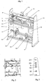
- In den beigefügten Zeichnungen ist eine vorteilhafte Ausführungsform dargestellt. Es zeigen:
- Fig. 1
- einen Kompakten Fluid-Temperierungsblock in Perspektivansicht;
- Fig. 2
- den Fluid-Temperierungsblock in Seitenansicht; und
- Fig. 3
- eine Vorderansicht des Fluid-Temperierungsblocks.
- Einzelkomponenten sind in einem Träger oder Gestell bestehend aus vertikalen Seitenwänden und mehreren horizontalen Verstrebungen angeordnet und befestigt.
- Eine der mindestens zwei Seitenwände dient als fluidische Anschlussplatte 1, auf der sämtliche Ein- und Ausgänge angeordnet sind: Produkteingang 17, Kondensatausgang 18, Dampfausgang 19, Dampfeingang 20 und Produktausgang 21. Außerdem befindet sich zumindest der Handgriff des Bypassventils 3 auf der Anschlussplatte, womit die Dampflinie über den Dampfausgang 19 entleert werden kann.
- Im Träger verlaufen zwei voneinander getrennte Leitungsstränge für Dampf und Produkt, die sich über vier horizontale Leitungsabschnitte erstrecken - je zwei für Dampf und Produkt - und die alle im vertikal angeordneten Wärmetauscher 9 enden. Der Wärmetauscher 9 ist benachbart der Seitenwand, die der fluidischen Anschlussplatte 1 gegenüber liegt. Die Produkt führenden Leitungsabschnitte weisen ein leichtes Gefälle nach oben und unten auf, wodurch sichergestellt wird, dass diese Abschnitte sich nach Abschalten des Systems selbst entleeren und auch im Wärmetauscher kein Produkt verbleibt.
- Bei Inbetriebnahme der Anlage wird zunächst der für Dampf vorgesehene Leitungsstrang mit Hilfe des Entlüftungsventils 2 von sich darin eventuell befindender störender Luft befreit.
- Über das mittels Steuerung 16 geöffnete Dampfeinlassventil 4 gelangt durch den Filter 5 gereinigter Dampf durch den Dampfeingang 20 zum Dampfregelventil 6, welches die dem oberen Ende des vertikal angeordneten Wärmetauschers 9 zugeführte Dampfmenge regelt in Abhängigkeit des gemessenen Drucks des Dampfs mittels Drucktransmitter 7 und der vom Temperatursensor 14 gemessenen Temperatur des Produkts. Der Drucktransmitter 7 befindet sich zwischen Dampfregelventil 6 und Wärmetauscher 9.
- Das nachgeschaltete Sicherheitsventil 8 verhindert, dass der Dampfdruck definierte Werte übersteigt.
- Am unteren Ende des Wärmetauschers 9 gelangt ein Gemisch aus Dampf und Kondensat zum Kondensatableiter 11, der gewährleistet, dass ausschließlich Wasser ohne Dampfanteil zum Kondensatausgang 18 geführt wird.
- Das Rückschlagventil 12 verhindert, dass Wasser vom Kondensatausgang 18 in den Kondensatableiter 11 zurückfließt.
- Optional ist das Entleerungsventil 10 im unteren Dampfleitungsabschnitt angeordnet, womit die Kondensatleitung entleert werden kann, falls der Kondensatableiter 11 ausfallen sollte.
- Im zweiten Leitungsstrang, der von der Dampflinie getrennt ist, gelangt Medium beispielsweise WFI über den Produkteingang 17 und das geöffnete Produkteinlassventil 13 zum unteren Ende des vertikal angeordneten Wärmetauschers 9. Das Produkteinlassventil 13 ist bei Betrieb der Anlage geöffnet und kann für Wartungszwecke geschlossen werden.
- Im Wärmetauscher 9 wird das Medium auf die gewünschte Temperatur gebracht, welche vom Temperatursensor 14 gemessen und der Steuerung 16 übermittelt wird.
- Der Sensor 14 befindet sich im horizontalen Leitungszweig, der mit dem oberen Ende des vertikal angeordneten Wärmetauschers 9 verbunden ist und der zum Produktausgang 21 führt.
- Bei geöffnetem Produktauslassventil 15 kann im Produktausgang 21 Produkt mit gewünschter Temperatur entnommen werden.
- Das Produkteinlassventil 13 ist zwecks Selbstentleerungsmöglichkeit ebenso wie das Produktauslassventil 15 in spezieller schräger Einbaulage für Selbstentleerung montiert.
- Ein weiteres Ausführungsbeispiel ist als Rahmenkonstruktion ausgeführt und weist die in den Zeichnungen dargestellten Seitenflächen nicht auf, wohl aber die einheitliche Anordnung aller Fluidanschlüsse auf derselben Seite.
- Das vorgeschlagene System bestehend aus den beschriebenen Einzelkomponenten, angeordnet auf einem Träger kann optional vollständig verkleidet sein.
- Alle Medium führenden Teile werden für Hygieneanwendungen aus Edelstahl gefertigt.
Bezugszeichenliste 1 Fluidische Anschlussplatte 16 Steuerung 2 Entlüftungsventil 17 Produkteingang 3 Bypassventil 18 Kondensatausgang 4 Dampfeinlassventil 19 Dampfausgang 5 Filter 20 Dampfeingang 6 Dampfregelventil 21 Produktausgang 7 Drucktransmitter 8 Sicherheitsventil 9 Wärmetauscher in hygienischer Ausführung 10 Entleerungsventil 11 Kondensatableiter 12 Rückschlagventil 13 Produkteinlassventil 14 Temperatursensor 15 Produktauslassventil
Claims (11)
- Kompakter Fluid-Temperierungsblock, der ein gemeinsames Gestell aufweist und einen in diesem gemeinsamen Gestell angeordneten Wärmetauscher (9) mit einem ersten Zulauf und einem ersten Ablauf für ein fluides Wärmeträgermedium wie Wasserdampf und einem zweiten Zulauf und einem zweiten Ablauf für ein zu temperierendes fluides Produkt wie Reinwasser umfasst sowie Durchfluß-Steuerelemente für Wärmeträgermedium und Produkt aufweist, wobei die ersten und zweiten Zuläufe und die ersten und zweiten Abläufe an einer gemeinsamen Anschlussfläche münden, wobei der Wärmetauscher (9) vertikal im Gestell angeordnet ist, dadurch gekennzeichnet, dass die Produkt führenden Leitungsstränge, das heißt der zweite Zulauf und der zweite Ablauf, ein leichtes Gefälle nach oben für einen sich im oberen Bereich des Gestells befindenden Leitungsabschnitt aufweisen und ein leichtes Gefälle nach unten für einen sich im unteren Bereich des Gestells befindenden Leitungsabschnitt, so dass nach einem Abschalten ein komplettes Entleeren des Produkts sichergestellt ist.
- Kompakter Fluid-Temperierungsblock nach Anspruch 1, bei dem die ersten und zweiten Zuläufe und die ersten und zweiten Abläufe im Wesentlichen horizontal im Gestell angeordnet sind.
- Kompakter Fluid-Temperierungsblock nach einem der Ansprüche 1 oder 2, bei dem eine Kondensat-Ableitung (11) von dem Wärmetauscher (9) zu der gemeinsamen Anschlussfläche geführt ist.
- Kompakter Fluid-Temperierungsblock nach einem der Ansprüche 1 bis 3, bei dem Verschleißkomponenten mit Flanschverbindungen angeschlossen sind und alle anderen Verbindungen geschweißt sind.
- Kompakter Fluid-Temperierungsblock nach einem der Ansprüche 1 bis 4, bei dem auch Temperatur- und Drucksensoren integriert sind.
- Kompakter Fluid-Temperierungsblock nach einem der Ansprüche 1 bis 5, bei dem eine Bypassleitung vom ersten Zulauf für das Wärmeträgermedium über ein Ventil zu der gemeinsamen Anschlussfläche geführt ist.
- Kompakter Fluid-Temperierungsblock nach einem der Ansprüche 1 bis 6, bei dem das Gestell eine Rahmenkonstruktion mit zwei parallelen Seitenflächen ist und die Seitenflächen durch horizontale Streben verbunden sind.
- Kompakter Fluid-Temperierungsblock nach einem der Ansprüche 1 bis 7, bei dem die ersten und zweiten Zuläufe und ersten und zweiten Abläufe für das Produkt und für das Wärmeträgermedium im Wesentlichen senkrecht in Bezug auf den Wärmetauscher (9) übereinander und im Abstand voneinander angeordnet sind.
- Kompakter Fluid-Temperierungsblock nach Anspruch 3 und Anspruch 8, bei dem die Kondensat-Ableitung (11) in einem Freiraum oberhalb eines Leitungsabschnitts, der zum Kondensatausgang (18) führt, angeordnet ist.
- Kompakter Fluid-Temperierungsblock nach einem der Ansprüche 1 bis 9, der zusätzlich ein Regelventil für die Zufuhr des Wärmeträgermediums umfasst und das Regelventil einen Antrieb aufweist, der sich in einen Freiraum senkrecht unterhalb der Zuleitung für das Wärmeträgermedium erstreckt.
- Kompakter Fluid-Temperierungsblock nach einem der Ansprüche 1 bis 10, dessen Außenabmessungen den Durchgang durch eine Normöffnung, insbesondere eine Normtüröffnung, zulassen.
Applications Claiming Priority (1)
| Application Number | Priority Date | Filing Date | Title |
|---|---|---|---|
| DE202008003228U DE202008003228U1 (de) | 2008-03-07 | 2008-03-07 | Fluid-Temperierungsblock |
Publications (3)
| Publication Number | Publication Date |
|---|---|
| EP2098790A2 EP2098790A2 (de) | 2009-09-09 |
| EP2098790A3 EP2098790A3 (de) | 2014-10-01 |
| EP2098790B1 true EP2098790B1 (de) | 2017-08-02 |
Family
ID=39646448
Family Applications (1)
| Application Number | Title | Priority Date | Filing Date |
|---|---|---|---|
| EP09002530.5A Not-in-force EP2098790B1 (de) | 2008-03-07 | 2009-02-23 | Fluid-Temperierungsblock |
Country Status (2)
| Country | Link |
|---|---|
| EP (1) | EP2098790B1 (de) |
| DE (1) | DE202008003228U1 (de) |
Family Cites Families (4)
| Publication number | Priority date | Publication date | Assignee | Title |
|---|---|---|---|---|
| FR2742214B1 (fr) * | 1995-12-08 | 1999-08-20 | Chaffoteaux Et Maury | Appareils generateurs d'eau chaude sanitaire et d'eau de chauffage central |
| CA2478440A1 (en) * | 2004-06-23 | 2005-12-23 | Rominn Laboratories Inc. | Compact steam-fed heat exchange system |
| DE502005009452D1 (de) * | 2005-03-15 | 2010-06-02 | Grundfos Management As | Baueinheit für eine Kompaktheizungsanlage |
| WO2007065239A1 (en) * | 2005-12-06 | 2007-06-14 | Brewster Jackie L | Method and apparatus for providing on-demand hot water |
-
2008
- 2008-03-07 DE DE202008003228U patent/DE202008003228U1/de not_active Expired - Lifetime
-
2009
- 2009-02-23 EP EP09002530.5A patent/EP2098790B1/de not_active Not-in-force
Non-Patent Citations (1)
| Title |
|---|
| None * |
Also Published As
| Publication number | Publication date |
|---|---|
| DE202008003228U1 (de) | 2008-07-24 |
| EP2098790A3 (de) | 2014-10-01 |
| EP2098790A2 (de) | 2009-09-09 |
Similar Documents
| Publication | Publication Date | Title |
|---|---|---|
| EP2231316B1 (de) | Behälterandordnung mit einem behälter mit flexibler wandung | |
| EP2254422B1 (de) | Gargerät mit einer wrasenkondensiereinrichtung | |
| DE102007011084B4 (de) | Ventilvorrichtung für eine Anlage zur Produktführung, eine derartige Anlage sowie ein Verfahren zum Betreiben derselben | |
| DE19808236A1 (de) | Vorrichtung zum Belüften von Packungen unter keimarmen Bedingungen | |
| EP2366923A2 (de) | Ventilbaugruppe | |
| EP2636958A2 (de) | Heizkreisverteiler mit integrierter hydraulischer Weiche | |
| DE3321195C2 (de) | ||
| EP2098790A2 (de) | Fluid-Temperierungsblock | |
| DE102016201342B4 (de) | Vorrichtung und Dampflanze zum Aufschäumen und/oder Erwärmen von Milch | |
| WO2014174112A1 (de) | Spritzgiessmaschine mit einer im bereich der einfüllzone angeordneten luftgebläsekühleinrichtung | |
| EP0605804B1 (de) | Vorrichtung zum wahlweisen Beaufschlagen von Formen für die Kunststoffverarbeitung mit einer Flüssigkeit oder einem unter Druck stehenden Gas | |
| EP2359038A1 (de) | Vorrichtung zur verrohrung von prozessanlagen der nahrungsmittel- und getränkeindustrie und verfahren zum betrieb einer vorrichtung | |
| EP3228943B1 (de) | Verbindungseinheit zum verbinden einer druckhalte- und/oder entgasungsvorrichtung mit einem heizkreisverteiler einer heizungsanlage | |
| WO2024149673A1 (de) | Verfahren zur inaktivierung von viren in einem fluid | |
| DE2112375B2 (de) | Vorrichtung zum Sterilisieren von Gegenständen | |
| EP1277014A1 (de) | Dampfinjektor | |
| DE102017109235B4 (de) | Vorrichtung zum Dosieren einer Schmelze | |
| EP3222148A1 (de) | Temperiermodul | |
| DE202018100616U1 (de) | Einrichtung zum Erzeugen von Dampf | |
| DE9308343U1 (de) | Einrichtung zur Wärmebehandlung von insbesondere Milch | |
| EP1098008B1 (de) | Verdampfer | |
| DE102018102512A1 (de) | Einrichtung zum Erzeugen von Dampf | |
| EP3743666B1 (de) | Dosiermodul mit einer temperierbaren dosiereinrichtung und verfahren zum temperieren einer dosiereinrichtung | |
| EP0814294A1 (de) | Anschlussvorrichtung | |
| DE4434407A1 (de) | Anlage zum Reinigen und Befüllen einer Folge von Getränkebehältern |
Legal Events
| Date | Code | Title | Description |
|---|---|---|---|
| PUAI | Public reference made under article 153(3) epc to a published international application that has entered the european phase |
Free format text: ORIGINAL CODE: 0009012 |
|
| AK | Designated contracting states |
Kind code of ref document: A2 Designated state(s): AT BE BG CH CY CZ DE DK EE ES FI FR GB GR HR HU IE IS IT LI LT LU LV MC MK MT NL NO PL PT RO SE SI SK TR |
|
| AX | Request for extension of the european patent |
Extension state: AL BA RS |
|
| RAP1 | Party data changed (applicant data changed or rights of an application transferred) |
Owner name: BUERKERT WERKE GMBH |
|
| PUAL | Search report despatched |
Free format text: ORIGINAL CODE: 0009013 |
|
| AK | Designated contracting states |
Kind code of ref document: A3 Designated state(s): AT BE BG CH CY CZ DE DK EE ES FI FR GB GR HR HU IE IS IT LI LT LU LV MC MK MT NL NO PL PT RO SE SI SK TR |
|
| AX | Request for extension of the european patent |
Extension state: AL BA RS |
|
| RIC1 | Information provided on ipc code assigned before grant |
Ipc: F24H 9/14 20060101ALI20140827BHEP Ipc: F24D 3/10 20060101AFI20140827BHEP Ipc: F24D 19/00 20060101ALI20140827BHEP |
|
| 17P | Request for examination filed |
Effective date: 20150401 |
|
| RBV | Designated contracting states (corrected) |
Designated state(s): AT BE BG CH CY CZ DE DK EE ES FI FR GB GR HR HU IE IS IT LI LT LU LV MC MK MT NL NO PL PT RO SE SI SK TR |
|
| RBV | Designated contracting states (corrected) |
Designated state(s): AT BE BG CH CY CZ DE DK EE ES FI FR GB GR HR HU IE IS IT LI LT LU LV MC MK MT NL NO PL PT RO SE SI SK TR |
|
| AKX | Designation fees paid |
Designated state(s): AT BE BG CH CY CZ DE DK EE ES FI FR GB GR HR HU IE IS IT LI LT LU LV MC MK MT NL NO PL PT RO SE SI SK TR |
|
| AXX | Extension fees paid |
Extension state: RS Extension state: AL Extension state: BA |
|
| 17Q | First examination report despatched |
Effective date: 20151112 |
|
| GRAP | Despatch of communication of intention to grant a patent |
Free format text: ORIGINAL CODE: EPIDOSNIGR1 |
|
| STAA | Information on the status of an ep patent application or granted ep patent |
Free format text: STATUS: GRANT OF PATENT IS INTENDED |
|
| INTG | Intention to grant announced |
Effective date: 20170302 |
|
| GRAS | Grant fee paid |
Free format text: ORIGINAL CODE: EPIDOSNIGR3 |
|
| GRAA | (expected) grant |
Free format text: ORIGINAL CODE: 0009210 |
|
| STAA | Information on the status of an ep patent application or granted ep patent |
Free format text: STATUS: THE PATENT HAS BEEN GRANTED |
|
| AK | Designated contracting states |
Kind code of ref document: B1 Designated state(s): AT BE BG CH CY CZ DE DK EE ES FI FR GB GR HR HU IE IS IT LI LT LU LV MC MK MT NL NO PL PT RO SE SI SK TR |
|
| REG | Reference to a national code |
Ref country code: GB Ref legal event code: FG4D Free format text: NOT ENGLISH |
|
| REG | Reference to a national code |
Ref country code: CH Ref legal event code: EP Ref country code: AT Ref legal event code: REF Ref document number: 914911 Country of ref document: AT Kind code of ref document: T Effective date: 20170815 |
|
| REG | Reference to a national code |
Ref country code: IE Ref legal event code: FG4D Free format text: LANGUAGE OF EP DOCUMENT: GERMAN |
|
| REG | Reference to a national code |
Ref country code: DE Ref legal event code: R096 Ref document number: 502009014202 Country of ref document: DE |
|
| REG | Reference to a national code |
Ref country code: NL Ref legal event code: MP Effective date: 20170802 |
|
| REG | Reference to a national code |
Ref country code: LT Ref legal event code: MG4D |
|
| PG25 | Lapsed in a contracting state [announced via postgrant information from national office to epo] |
Ref country code: HR Free format text: LAPSE BECAUSE OF FAILURE TO SUBMIT A TRANSLATION OF THE DESCRIPTION OR TO PAY THE FEE WITHIN THE PRESCRIBED TIME-LIMIT Effective date: 20170802 Ref country code: NL Free format text: LAPSE BECAUSE OF FAILURE TO SUBMIT A TRANSLATION OF THE DESCRIPTION OR TO PAY THE FEE WITHIN THE PRESCRIBED TIME-LIMIT Effective date: 20170802 Ref country code: FI Free format text: LAPSE BECAUSE OF FAILURE TO SUBMIT A TRANSLATION OF THE DESCRIPTION OR TO PAY THE FEE WITHIN THE PRESCRIBED TIME-LIMIT Effective date: 20170802 Ref country code: SE Free format text: LAPSE BECAUSE OF FAILURE TO SUBMIT A TRANSLATION OF THE DESCRIPTION OR TO PAY THE FEE WITHIN THE PRESCRIBED TIME-LIMIT Effective date: 20170802 Ref country code: LT Free format text: LAPSE BECAUSE OF FAILURE TO SUBMIT A TRANSLATION OF THE DESCRIPTION OR TO PAY THE FEE WITHIN THE PRESCRIBED TIME-LIMIT Effective date: 20170802 Ref country code: NO Free format text: LAPSE BECAUSE OF FAILURE TO SUBMIT A TRANSLATION OF THE DESCRIPTION OR TO PAY THE FEE WITHIN THE PRESCRIBED TIME-LIMIT Effective date: 20171102 |
|
| PG25 | Lapsed in a contracting state [announced via postgrant information from national office to epo] |
Ref country code: IS Free format text: LAPSE BECAUSE OF FAILURE TO SUBMIT A TRANSLATION OF THE DESCRIPTION OR TO PAY THE FEE WITHIN THE PRESCRIBED TIME-LIMIT Effective date: 20171202 Ref country code: LV Free format text: LAPSE BECAUSE OF FAILURE TO SUBMIT A TRANSLATION OF THE DESCRIPTION OR TO PAY THE FEE WITHIN THE PRESCRIBED TIME-LIMIT Effective date: 20170802 Ref country code: GR Free format text: LAPSE BECAUSE OF FAILURE TO SUBMIT A TRANSLATION OF THE DESCRIPTION OR TO PAY THE FEE WITHIN THE PRESCRIBED TIME-LIMIT Effective date: 20171103 Ref country code: ES Free format text: LAPSE BECAUSE OF FAILURE TO SUBMIT A TRANSLATION OF THE DESCRIPTION OR TO PAY THE FEE WITHIN THE PRESCRIBED TIME-LIMIT Effective date: 20170802 Ref country code: BG Free format text: LAPSE BECAUSE OF FAILURE TO SUBMIT A TRANSLATION OF THE DESCRIPTION OR TO PAY THE FEE WITHIN THE PRESCRIBED TIME-LIMIT Effective date: 20171102 Ref country code: PL Free format text: LAPSE BECAUSE OF FAILURE TO SUBMIT A TRANSLATION OF THE DESCRIPTION OR TO PAY THE FEE WITHIN THE PRESCRIBED TIME-LIMIT Effective date: 20170802 |
|
| PG25 | Lapsed in a contracting state [announced via postgrant information from national office to epo] |
Ref country code: DK Free format text: LAPSE BECAUSE OF FAILURE TO SUBMIT A TRANSLATION OF THE DESCRIPTION OR TO PAY THE FEE WITHIN THE PRESCRIBED TIME-LIMIT Effective date: 20170802 Ref country code: RO Free format text: LAPSE BECAUSE OF FAILURE TO SUBMIT A TRANSLATION OF THE DESCRIPTION OR TO PAY THE FEE WITHIN THE PRESCRIBED TIME-LIMIT Effective date: 20170802 Ref country code: CZ Free format text: LAPSE BECAUSE OF FAILURE TO SUBMIT A TRANSLATION OF THE DESCRIPTION OR TO PAY THE FEE WITHIN THE PRESCRIBED TIME-LIMIT Effective date: 20170802 |
|
| REG | Reference to a national code |
Ref country code: DE Ref legal event code: R097 Ref document number: 502009014202 Country of ref document: DE |
|
| PG25 | Lapsed in a contracting state [announced via postgrant information from national office to epo] |
Ref country code: IT Free format text: LAPSE BECAUSE OF FAILURE TO SUBMIT A TRANSLATION OF THE DESCRIPTION OR TO PAY THE FEE WITHIN THE PRESCRIBED TIME-LIMIT Effective date: 20170802 Ref country code: EE Free format text: LAPSE BECAUSE OF FAILURE TO SUBMIT A TRANSLATION OF THE DESCRIPTION OR TO PAY THE FEE WITHIN THE PRESCRIBED TIME-LIMIT Effective date: 20170802 Ref country code: SK Free format text: LAPSE BECAUSE OF FAILURE TO SUBMIT A TRANSLATION OF THE DESCRIPTION OR TO PAY THE FEE WITHIN THE PRESCRIBED TIME-LIMIT Effective date: 20170802 |
|
| PLBE | No opposition filed within time limit |
Free format text: ORIGINAL CODE: 0009261 |
|
| STAA | Information on the status of an ep patent application or granted ep patent |
Free format text: STATUS: NO OPPOSITION FILED WITHIN TIME LIMIT |
|
| 26N | No opposition filed |
Effective date: 20180503 |
|
| PG25 | Lapsed in a contracting state [announced via postgrant information from national office to epo] |
Ref country code: SI Free format text: LAPSE BECAUSE OF FAILURE TO SUBMIT A TRANSLATION OF THE DESCRIPTION OR TO PAY THE FEE WITHIN THE PRESCRIBED TIME-LIMIT Effective date: 20170802 |
|
| REG | Reference to a national code |
Ref country code: CH Ref legal event code: PL |
|
| PG25 | Lapsed in a contracting state [announced via postgrant information from national office to epo] |
Ref country code: MT Free format text: LAPSE BECAUSE OF FAILURE TO SUBMIT A TRANSLATION OF THE DESCRIPTION OR TO PAY THE FEE WITHIN THE PRESCRIBED TIME-LIMIT Effective date: 20170802 Ref country code: MC Free format text: LAPSE BECAUSE OF FAILURE TO SUBMIT A TRANSLATION OF THE DESCRIPTION OR TO PAY THE FEE WITHIN THE PRESCRIBED TIME-LIMIT Effective date: 20170802 |
|
| GBPC | Gb: european patent ceased through non-payment of renewal fee |
Effective date: 20180223 |
|
| REG | Reference to a national code |
Ref country code: IE Ref legal event code: MM4A |
|
| REG | Reference to a national code |
Ref country code: BE Ref legal event code: MM Effective date: 20180228 |
|
| PG25 | Lapsed in a contracting state [announced via postgrant information from national office to epo] |
Ref country code: LU Free format text: LAPSE BECAUSE OF NON-PAYMENT OF DUE FEES Effective date: 20180223 Ref country code: LI Free format text: LAPSE BECAUSE OF NON-PAYMENT OF DUE FEES Effective date: 20180228 Ref country code: CH Free format text: LAPSE BECAUSE OF NON-PAYMENT OF DUE FEES Effective date: 20180228 |
|
| REG | Reference to a national code |
Ref country code: FR Ref legal event code: ST Effective date: 20181031 |
|
| PG25 | Lapsed in a contracting state [announced via postgrant information from national office to epo] |
Ref country code: IE Free format text: LAPSE BECAUSE OF NON-PAYMENT OF DUE FEES Effective date: 20180223 |
|
| PG25 | Lapsed in a contracting state [announced via postgrant information from national office to epo] |
Ref country code: BE Free format text: LAPSE BECAUSE OF NON-PAYMENT OF DUE FEES Effective date: 20180228 Ref country code: FR Free format text: LAPSE BECAUSE OF NON-PAYMENT OF DUE FEES Effective date: 20180228 Ref country code: GB Free format text: LAPSE BECAUSE OF NON-PAYMENT OF DUE FEES Effective date: 20180223 |
|
| REG | Reference to a national code |
Ref country code: AT Ref legal event code: MM01 Ref document number: 914911 Country of ref document: AT Kind code of ref document: T Effective date: 20180223 |
|
| PG25 | Lapsed in a contracting state [announced via postgrant information from national office to epo] |
Ref country code: AT Free format text: LAPSE BECAUSE OF NON-PAYMENT OF DUE FEES Effective date: 20180223 |
|
| PG25 | Lapsed in a contracting state [announced via postgrant information from national office to epo] |
Ref country code: TR Free format text: LAPSE BECAUSE OF FAILURE TO SUBMIT A TRANSLATION OF THE DESCRIPTION OR TO PAY THE FEE WITHIN THE PRESCRIBED TIME-LIMIT Effective date: 20170802 |
|
| PG25 | Lapsed in a contracting state [announced via postgrant information from national office to epo] |
Ref country code: HU Free format text: LAPSE BECAUSE OF FAILURE TO SUBMIT A TRANSLATION OF THE DESCRIPTION OR TO PAY THE FEE WITHIN THE PRESCRIBED TIME-LIMIT; INVALID AB INITIO Effective date: 20090223 Ref country code: PT Free format text: LAPSE BECAUSE OF FAILURE TO SUBMIT A TRANSLATION OF THE DESCRIPTION OR TO PAY THE FEE WITHIN THE PRESCRIBED TIME-LIMIT Effective date: 20170802 |
|
| PG25 | Lapsed in a contracting state [announced via postgrant information from national office to epo] |
Ref country code: CY Free format text: LAPSE BECAUSE OF FAILURE TO SUBMIT A TRANSLATION OF THE DESCRIPTION OR TO PAY THE FEE WITHIN THE PRESCRIBED TIME-LIMIT Effective date: 20170802 Ref country code: MK Free format text: LAPSE BECAUSE OF NON-PAYMENT OF DUE FEES Effective date: 20170802 |
|
| PGFP | Annual fee paid to national office [announced via postgrant information from national office to epo] |
Ref country code: DE Payment date: 20230131 Year of fee payment: 15 |
|
| P01 | Opt-out of the competence of the unified patent court (upc) registered |
Effective date: 20230523 |
|
| REG | Reference to a national code |
Ref country code: DE Ref legal event code: R119 Ref document number: 502009014202 Country of ref document: DE |
|
| PG25 | Lapsed in a contracting state [announced via postgrant information from national office to epo] |
Ref country code: DE Free format text: LAPSE BECAUSE OF NON-PAYMENT OF DUE FEES Effective date: 20240903 |
|
| PG25 | Lapsed in a contracting state [announced via postgrant information from national office to epo] |
Ref country code: DE Free format text: LAPSE BECAUSE OF NON-PAYMENT OF DUE FEES Effective date: 20240903 |