EP2098713A1 - Thermoelectric heat recuperation system - Google Patents
Thermoelectric heat recuperation system Download PDFInfo
- Publication number
- EP2098713A1 EP2098713A1 EP08102333A EP08102333A EP2098713A1 EP 2098713 A1 EP2098713 A1 EP 2098713A1 EP 08102333 A EP08102333 A EP 08102333A EP 08102333 A EP08102333 A EP 08102333A EP 2098713 A1 EP2098713 A1 EP 2098713A1
- Authority
- EP
- European Patent Office
- Prior art keywords
- thermoelectric
- thermoelectric element
- cylinder liner
- internal combustion
- heat recuperation
- Prior art date
- Legal status (The legal status is an assumption and is not a legal conclusion. Google has not performed a legal analysis and makes no representation as to the accuracy of the status listed.)
- Withdrawn
Links
- 238000002485 combustion reaction Methods 0.000 claims abstract description 13
- 238000001816 cooling Methods 0.000 claims description 11
- XLYOFNOQVPJJNP-UHFFFAOYSA-N water Substances O XLYOFNOQVPJJNP-UHFFFAOYSA-N 0.000 claims description 5
- 239000000446 fuel Substances 0.000 description 5
- 239000000919 ceramic Substances 0.000 description 3
- 238000005266 casting Methods 0.000 description 1
- 238000010276 construction Methods 0.000 description 1
- 239000002826 coolant Substances 0.000 description 1
- 238000000034 method Methods 0.000 description 1
Images
Classifications
-
- F—MECHANICAL ENGINEERING; LIGHTING; HEATING; WEAPONS; BLASTING
- F02—COMBUSTION ENGINES; HOT-GAS OR COMBUSTION-PRODUCT ENGINE PLANTS
- F02F—CYLINDERS, PISTONS OR CASINGS, FOR COMBUSTION ENGINES; ARRANGEMENTS OF SEALINGS IN COMBUSTION ENGINES
- F02F1/00—Cylinders; Cylinder heads
- F02F1/02—Cylinders; Cylinder heads having cooling means
- F02F1/10—Cylinders; Cylinder heads having cooling means for liquid cooling
- F02F1/16—Cylinder liners of wet type
-
- H—ELECTRICITY
- H10—SEMICONDUCTOR DEVICES; ELECTRIC SOLID-STATE DEVICES NOT OTHERWISE PROVIDED FOR
- H10N—ELECTRIC SOLID-STATE DEVICES NOT OTHERWISE PROVIDED FOR
- H10N10/00—Thermoelectric devices comprising a junction of dissimilar materials, i.e. devices exhibiting Seebeck or Peltier effects
- H10N10/10—Thermoelectric devices comprising a junction of dissimilar materials, i.e. devices exhibiting Seebeck or Peltier effects operating with only the Peltier or Seebeck effects
- H10N10/13—Thermoelectric devices comprising a junction of dissimilar materials, i.e. devices exhibiting Seebeck or Peltier effects operating with only the Peltier or Seebeck effects characterised by the heat-exchanging means at the junction
Definitions
- the present invention concerns a system for recovering electric energy during the functioning of an internal combustion engine.
- thermoelectric elements in the exhaust stream or in the cooling system.
- thermoelectric elements in the exhaust stream or in the cooling system.
- thermoelectric elements require the presence of a secondary heat exchanger in order to increase the efficiency of the thermoelectric element.
- the presence of the additional heat exchanger contributes to increase the backpressure of the engine and, consequently, the fuel consumption.
- the aim of the present invention is to eliminate or reduce the drawbacks afflicting the known thermoelectric heat recuperation methods.
- thermoelectric heat recuperation system with increased efficiency.
- Another object of the present invention is to provide a thermoelectric heat recuperation system suitable to avoid the use of additional elements such as the secondary heat exchanger.
- thermoelectric heat recuperation system particularly for internal combustion engines, comprising at least one thermoelectric element and at least an electric power circuit, characterized in that said at least one thermoelectric element is positioned close to the cylinder liner of at least one of the engine cylinders in order to convert into electric current the heat of the internal combustion engine.
- thermoelectric heat recuperation system comprises at least a thermoelectric element 3 which is positioned near at least one of the cylinders of the internal combustion engine, the engine being generally indicated with reference number 1.
- thermoelectric element should be positioned around the cylinder. More in details, the thermoelectric element could be integrated in the casting of the internal combustion engine or it could be a part of an inserted cylinder liner assembly.
- the inner and outer housing are electrically insulating, typically they consist of a ceramic plate.
- the inner ceramic housing could be a ceramic cylinder liner.
- the inner connections of the elements can be pressed or sintered or realized in any innovative way.
- the elements can also be located at the other parts forming the boundary of the combustion chamber as the cylinder head or the piston.
- thermoelectric insert is advantageously positioned close to the cylinder, more in particular it should contact or surround the cylinder liner.
- thermoelectric element 3 is positioned between the cylinder liner 2 and the water cooling jacket 4.
- T H The temperature of the thermoelectric element on the hot side
- T C the temperature of the element on the water cooling jacket side
- thermoelectric element close to the cylinder liner As per the present invention, it is not necessary to provide an auxiliary heat exchanger in order to dissipate the exceeding heat around the thermoelectric element. In fact, thanks to the presence of the water cooling jacket surrounding the thermoelectric element, no additional cooling system is necessary.
- thermoelectric element allows to recover electric energy from the heat generated by the engine. Then, the electric energy can be stored in a battery or directly used to provide electric power to the engine or to the vehicle's utilities in general. Thanks to the heat transfer from the cylinder, the loading of the engine cooling system is reduced, and this results in a further fuel consumption reduction. It has been shown that the present invention achieves the aim and the objects proposed.
- thermoelectric heat recuperation system allows to avoid the presence of the auxiliary heat exchanger commonly used in the known systems in which thermoelectric elements are located in the exhaust stream or in the cooling system.
- the system according to the present invention allows to avoid the weight and the pressure losses in the exhaust coolant flow associated to the presence of the secondary heat exchanger.
- the system according to the present invention allows to reduce fuel consumption by means of the reduction of the loading of the engine cooling system.
- the heat is converted by the thermoelectric element immediately at the cylinder, so reducing the load of the engine cooling system and, therefore, reducing the fuel consumption.
Landscapes
- Engineering & Computer Science (AREA)
- Chemical & Material Sciences (AREA)
- Combustion & Propulsion (AREA)
- Mechanical Engineering (AREA)
- General Engineering & Computer Science (AREA)
- Cylinder Crankcases Of Internal Combustion Engines (AREA)
Abstract
Description
- The present invention concerns a system for recovering electric energy during the functioning of an internal combustion engine.
- As it is known, it is possible to recover electric energy from the heat generated by the engine. In particular, it is known to recover electric energy by means of the application of thermoelectric elements in the exhaust stream or in the cooling system. These known system require the presence of a secondary heat exchanger in order to increase the efficiency of the thermoelectric element.
- The presence of the secondary heat exchanger is one of the drawbacks of the known systems because it limits the efficiency of the thermoelectric heat recuperation.
- Moreover, the presence of the additional heat exchanger contributes to increase the backpressure of the engine and, consequently, the fuel consumption.
- The aim of the present invention is to eliminate or reduce the drawbacks afflicting the known thermoelectric heat recuperation methods.
- Within this aim, it is an object of the present invention to provide a thermoelectric heat recuperation system with increased efficiency.
- Another object of the present invention is to provide a thermoelectric heat recuperation system suitable to avoid the use of additional elements such as the secondary heat exchanger.
- Moreover, it is an object of the present invention to reduce the load of the engine and, therefore, to reduce the fuel consumption.
- This aim, and these objects of the present invention are achieved by a thermoelectric heat recuperation system particularly for internal combustion engines, comprising at least one thermoelectric element and at least an electric power circuit, characterized in that said at least one thermoelectric element is positioned close to the cylinder liner of at least one of the engine cylinders in order to convert into electric current the heat of the internal combustion engine.
- Further advantages of the present invention will become clear from the following detailed description of a preferred embodiment and the drawings that are attached hereto, which are merely illustrative and not limitative of the present invention, in which:
-
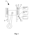
figure 1 schematically represents a cross-section view of a cylinder of an internal combustion engine provided with a thermoelectric element according to the thermoelectric heat recuperation system of the present invention. - With reference to
figure 1 , the thermoelectric heat recuperation system according to the present invention comprises at least athermoelectric element 3 which is positioned near at least one of the cylinders of the internal combustion engine, the engine being generally indicated withreference number 1. - In particular, the thermoelectric element should be positioned around the cylinder. More in details, the thermoelectric element could be integrated in the casting of the internal combustion engine or it could be a part of an inserted cylinder liner assembly.
- Advantageously, a series of elements to sum up to a suitable electric voltage is provided. Therefore, the inner and outer housing are electrically insulating, typically they consist of a ceramic plate. The inner ceramic housing could be a ceramic cylinder liner. The inner connections of the elements can be pressed or sintered or realized in any innovative way.
- The elements can also be located at the other parts forming the boundary of the combustion chamber as the cylinder head or the piston.
- As per
figure 1 , the thermoelectric insert is advantageously positioned close to the cylinder, more in particular it should contact or surround the cylinder liner. - In the embodiment shown in
figure 1 as an example of the present invention, thethermoelectric element 3 is positioned between the cylinder liner 2 and thewater cooling jacket 4. The temperature of the thermoelectric element on the hot side is indicated with TH, while the temperature of the element on the water cooling jacket side is indicated with TC. - With the positioning of the thermoelectric element close to the cylinder liner as per the present invention, it is not necessary to provide an auxiliary heat exchanger in order to dissipate the exceeding heat around the thermoelectric element. In fact, thanks to the presence of the water cooling jacket surrounding the thermoelectric element, no additional cooling system is necessary.
- The thermoelectric element allows to recover electric energy from the heat generated by the engine. Then, the electric energy can be stored in a battery or directly used to provide electric power to the engine or to the vehicle's utilities in general. Thanks to the heat transfer from the cylinder, the loading of the engine cooling system is reduced, and this results in a further fuel consumption reduction. It has been shown that the present invention achieves the aim and the objects proposed.
- More in detail, it has been shown that the thermoelectric heat recuperation system according to the present invention allows to avoid the presence of the auxiliary heat exchanger commonly used in the known systems in which thermoelectric elements are located in the exhaust stream or in the cooling system. As a consequence, the system according to the present invention allows to avoid the weight and the pressure losses in the exhaust coolant flow associated to the presence of the secondary heat exchanger.
- Moreover, the system according to the present invention allows to reduce fuel consumption by means of the reduction of the loading of the engine cooling system. In fact, the heat is converted by the thermoelectric element immediately at the cylinder, so reducing the load of the engine cooling system and, therefore, reducing the fuel consumption.
- It will be apparent to the person skilled in the art that other alternative and equivalent embodiments of the invention can be conceived and reduced to practice without departing from the true spirit of the invention.
- From the description set forth above it will be possible for the person skilled in the art to embody the invention without introducing any further construction details.
Claims (7)
- Thermoelectric heat recuperation system particularly for internal combustion engines (1), comprising at least one thermoelectric element (3) and at least an electric power circuit, characterized in that said at least one thermoelectric element (3) is positioned close to the cylinder liner (2) of at least one of the engine cylinders in order to convert into electric current the heat of the internal combustion engine.
- Thermoelectric heat recuperation system according to claim 1, characterized in that said thermoelectric element (3) directly contacts the cylinder liner (2).
- Thermoelectric heat recuperation system according to one of the previous claims, characterized in that said thermoelectric element (3) surrounds the cylinder liner (2).
- Thermoelectric heat recuperation system according to one of the previous claims, characterized in that said thermoelectric element (3) is positioned between the cylinder liner (2) and the water cooling jacket (4) of the engine.
- Internal combustion engine (1), characterized in that it comprises at least one thermoelectric element (3) positioned close to the cylinder liner (2).
- Internal combustion engine (1) according to the preceding claim, characterized in that said thermoelectric element (3) contacts the cylinder liner (2).
- Internal combustion engine (1) according to the preceding claim, characterized in that said thermoelectric element (3) is positioned between the cylinder liner (2) and the water cooling jacket (4).
Priority Applications (1)
| Application Number | Priority Date | Filing Date | Title |
|---|---|---|---|
| EP08102333A EP2098713A1 (en) | 2008-03-06 | 2008-03-06 | Thermoelectric heat recuperation system |
Applications Claiming Priority (1)
| Application Number | Priority Date | Filing Date | Title |
|---|---|---|---|
| EP08102333A EP2098713A1 (en) | 2008-03-06 | 2008-03-06 | Thermoelectric heat recuperation system |
Publications (1)
| Publication Number | Publication Date |
|---|---|
| EP2098713A1 true EP2098713A1 (en) | 2009-09-09 |
Family
ID=39673375
Family Applications (1)
| Application Number | Title | Priority Date | Filing Date |
|---|---|---|---|
| EP08102333A Withdrawn EP2098713A1 (en) | 2008-03-06 | 2008-03-06 | Thermoelectric heat recuperation system |
Country Status (1)
| Country | Link |
|---|---|
| EP (1) | EP2098713A1 (en) |
Cited By (2)
| Publication number | Priority date | Publication date | Assignee | Title |
|---|---|---|---|---|
| DE102009017311A1 (en) * | 2009-04-11 | 2010-10-14 | Mag Europe Gmbh | Thermoelectric device for producing electrical energy from heat produced by internal combustion engine of motor vehicle, has generator arranged such that electrical energy is generated from heat guided from inner wall towards outer wall |
| DE102012215348A1 (en) * | 2012-08-29 | 2014-05-28 | Bayerische Motoren Werke Aktiengesellschaft | Liquid-cooled lifting cylinder combustion engine for motor car, has tubular thermo-electric module that is arranged between cylinder and coolant channel which is set to surround the aluminum crankcase |
Citations (6)
| Publication number | Priority date | Publication date | Assignee | Title |
|---|---|---|---|---|
| JPS63111269A (en) * | 1986-10-29 | 1988-05-16 | Mazda Motor Corp | Exhaust heat utilizing device for engine |
| JPS63111268A (en) * | 1986-10-29 | 1988-05-16 | Mazda Motor Corp | Exhaust heat utilizing device for engine |
| JPH03117617A (en) | 1989-09-29 | 1991-05-20 | Honda Motor Co Ltd | Cooling structure of internal combustion engine |
| WO2006030888A1 (en) * | 2004-09-17 | 2006-03-23 | Hino Motors, Ltd. | Exhaust heat recovery system |
| JP2006266212A (en) * | 2005-03-25 | 2006-10-05 | Mazda Motor Corp | Waste heat power generator for internal combustion engine |
| DE102006039024A1 (en) * | 2006-08-19 | 2008-02-21 | Deutsches Zentrum für Luft- und Raumfahrt e.V. | Thermo-generator for use in e.g. motor vehicle, for generating current from heat, has thermoelectric units arranged behind each other in axial direction of delivery pipe and insulated against each other at front sides by insulation layers |
-
2008
- 2008-03-06 EP EP08102333A patent/EP2098713A1/en not_active Withdrawn
Patent Citations (6)
| Publication number | Priority date | Publication date | Assignee | Title |
|---|---|---|---|---|
| JPS63111269A (en) * | 1986-10-29 | 1988-05-16 | Mazda Motor Corp | Exhaust heat utilizing device for engine |
| JPS63111268A (en) * | 1986-10-29 | 1988-05-16 | Mazda Motor Corp | Exhaust heat utilizing device for engine |
| JPH03117617A (en) | 1989-09-29 | 1991-05-20 | Honda Motor Co Ltd | Cooling structure of internal combustion engine |
| WO2006030888A1 (en) * | 2004-09-17 | 2006-03-23 | Hino Motors, Ltd. | Exhaust heat recovery system |
| JP2006266212A (en) * | 2005-03-25 | 2006-10-05 | Mazda Motor Corp | Waste heat power generator for internal combustion engine |
| DE102006039024A1 (en) * | 2006-08-19 | 2008-02-21 | Deutsches Zentrum für Luft- und Raumfahrt e.V. | Thermo-generator for use in e.g. motor vehicle, for generating current from heat, has thermoelectric units arranged behind each other in axial direction of delivery pipe and insulated against each other at front sides by insulation layers |
Cited By (2)
| Publication number | Priority date | Publication date | Assignee | Title |
|---|---|---|---|---|
| DE102009017311A1 (en) * | 2009-04-11 | 2010-10-14 | Mag Europe Gmbh | Thermoelectric device for producing electrical energy from heat produced by internal combustion engine of motor vehicle, has generator arranged such that electrical energy is generated from heat guided from inner wall towards outer wall |
| DE102012215348A1 (en) * | 2012-08-29 | 2014-05-28 | Bayerische Motoren Werke Aktiengesellschaft | Liquid-cooled lifting cylinder combustion engine for motor car, has tubular thermo-electric module that is arranged between cylinder and coolant channel which is set to surround the aluminum crankcase |
Similar Documents
| Publication | Publication Date | Title |
|---|---|---|
| Pang et al. | Review of engine cooling technologies for modern engines | |
| US8881522B2 (en) | Exhaust manifold | |
| US8997470B2 (en) | Exhaust gas purifying device for internal combustion engine | |
| WO1991003632A1 (en) | Cooling method of cylinder liner of engine | |
| EP1059432A3 (en) | Cooling apparatus for vehicular engine | |
| JP2010518796A (en) | Vehicle equipped with thermoelectric generator | |
| CN103306851B (en) | Cylinder sleeve temperature difference generation device for internal combustion engine waste heat recovery | |
| US20120055527A1 (en) | Structural element for thermally shielding engines or engine components, in particular a heat shield for combustion engines | |
| US20100269878A1 (en) | Internal combustion engine with thermoelectric generator | |
| JP3111922B2 (en) | Cylinder head structure of internal combustion engine equipped with solenoid valve | |
| US20150214458A1 (en) | Thermoelectric generator system for intercooler coupled to turbocharger | |
| US10634088B2 (en) | Coolant jacket for a liquid-cooled cylinder head | |
| EP3501934B1 (en) | Cooling system and method for a dual-powered railroad vehicle | |
| EP2098713A1 (en) | Thermoelectric heat recuperation system | |
| US6918365B2 (en) | System having an internal combustion engine and a fuel cell and method of making and using same | |
| JP4276610B2 (en) | Waste heat recovery device | |
| US20190103537A1 (en) | Engine with cylinder liner having a thermoelectric module, and method of operating the engine | |
| CN110529281A (en) | Cylinder liner including induction coil and the mixing internal combustion engine and dynamical system using it | |
| US9500160B2 (en) | Motor assembly | |
| CN214577407U (en) | High-efficient heat dissipation dry-type engine cylinder cover | |
| JP2011256757A (en) | Combustion chamber structure of compression ignition internal combustion engine | |
| JP2006266212A (en) | Waste heat power generator for internal combustion engine | |
| CN112423412A (en) | Electrical load resistor | |
| SE545626C2 (en) | A chassis and a vehicle provided with such a chassis | |
| RU2200862C2 (en) | Cylinder for internal combustion engine |
Legal Events
| Date | Code | Title | Description |
|---|---|---|---|
| PUAI | Public reference made under article 153(3) epc to a published international application that has entered the european phase |
Free format text: ORIGINAL CODE: 0009012 |
|
| AK | Designated contracting states |
Kind code of ref document: A1 Designated state(s): AT BE BG CH CY CZ DE DK EE ES FI FR GB GR HR HU IE IS IT LI LT LU LV MC MT NL NO PL PT RO SE SI SK TR |
|
| AX | Request for extension of the european patent |
Extension state: AL BA MK RS |
|
| 17P | Request for examination filed |
Effective date: 20100304 |
|
| 17Q | First examination report despatched |
Effective date: 20100408 |
|
| AKX | Designation fees paid |
Designated state(s): AT BE BG CH CY CZ DE DK EE ES FI FR GB GR HR HU IE IS IT LI LT LU LV MC MT NL NO PL PT RO SE SI SK TR |
|
| STAA | Information on the status of an ep patent application or granted ep patent |
Free format text: STATUS: THE APPLICATION IS DEEMED TO BE WITHDRAWN |
|
| 18D | Application deemed to be withdrawn |
Effective date: 20110308 |