EP2098677A1 - Verfahren zur Steuerung einer Schließ- und Öffnungsvorrichtung eines Öffnungselements mit Steuerung über Kabelverbindung - Google Patents
Verfahren zur Steuerung einer Schließ- und Öffnungsvorrichtung eines Öffnungselements mit Steuerung über Kabelverbindung Download PDFInfo
- Publication number
- EP2098677A1 EP2098677A1 EP09370004A EP09370004A EP2098677A1 EP 2098677 A1 EP2098677 A1 EP 2098677A1 EP 09370004 A EP09370004 A EP 09370004A EP 09370004 A EP09370004 A EP 09370004A EP 2098677 A1 EP2098677 A1 EP 2098677A1
- Authority
- EP
- European Patent Office
- Prior art keywords
- limit switches
- movable member
- mode
- switch
- electronic circuit
- Prior art date
- Legal status (The legal status is an assumption and is not a legal conclusion. Google has not performed a legal analysis and makes no representation as to the accuracy of the status listed.)
- Granted
Links
Images


Classifications
-
- E—FIXED CONSTRUCTIONS
- E06—DOORS, WINDOWS, SHUTTERS, OR ROLLER BLINDS IN GENERAL; LADDERS
- E06B—FIXED OR MOVABLE CLOSURES FOR OPENINGS IN BUILDINGS, VEHICLES, FENCES OR LIKE ENCLOSURES IN GENERAL, e.g. DOORS, WINDOWS, BLINDS, GATES
- E06B9/00—Screening or protective devices for wall or similar openings, with or without operating or securing mechanisms; Closures of similar construction
- E06B9/56—Operating, guiding or securing devices or arrangements for roll-type closures; Spring drums; Tape drums; Counterweighting arrangements therefor
- E06B9/68—Operating devices or mechanisms, e.g. with electric drive
-
- G—PHYSICS
- G05—CONTROLLING; REGULATING
- G05B—CONTROL OR REGULATING SYSTEMS IN GENERAL; FUNCTIONAL ELEMENTS OF SUCH SYSTEMS; MONITORING OR TESTING ARRANGEMENTS FOR SUCH SYSTEMS OR ELEMENTS
- G05B19/00—Program-control systems
- G05B19/02—Program-control systems electric
- G05B19/42—Recording and playback systems, i.e. in which the program is recorded from a cycle of operations, e.g. the cycle of operations being manually controlled, after which this record is played back on the same machine
-
- E—FIXED CONSTRUCTIONS
- E05—LOCKS; KEYS; WINDOW OR DOOR FITTINGS; SAFES
- E05Y—INDEXING SCHEME ASSOCIATED WITH SUBCLASSES E05D AND E05F, RELATING TO CONSTRUCTION ELEMENTS, ELECTRIC CONTROL, POWER SUPPLY, POWER SIGNAL OR TRANSMISSION, USER INTERFACES, MOUNTING OR COUPLING, DETAILS, ACCESSORIES, AUXILIARY OPERATIONS NOT OTHERWISE PROVIDED FOR, APPLICATION THEREOF
- E05Y2400/00—Electronic control; Electrical power; Power supply; Power or signal transmission; User interfaces
- E05Y2400/10—Electronic control
- E05Y2400/32—Position control, detection or monitoring
- E05Y2400/334—Position control, detection or monitoring by using pulse generators
- E05Y2400/34—Pulse count limit setting
-
- E—FIXED CONSTRUCTIONS
- E05—LOCKS; KEYS; WINDOW OR DOOR FITTINGS; SAFES
- E05Y—INDEXING SCHEME ASSOCIATED WITH SUBCLASSES E05D AND E05F, RELATING TO CONSTRUCTION ELEMENTS, ELECTRIC CONTROL, POWER SUPPLY, POWER SIGNAL OR TRANSMISSION, USER INTERFACES, MOUNTING OR COUPLING, DETAILS, ACCESSORIES, AUXILIARY OPERATIONS NOT OTHERWISE PROVIDED FOR, APPLICATION THEREOF
- E05Y2800/00—Details, accessories and auxiliary operations not otherwise provided for
-
- E—FIXED CONSTRUCTIONS
- E06—DOORS, WINDOWS, SHUTTERS, OR ROLLER BLINDS IN GENERAL; LADDERS
- E06B—FIXED OR MOVABLE CLOSURES FOR OPENINGS IN BUILDINGS, VEHICLES, FENCES OR LIKE ENCLOSURES IN GENERAL, e.g. DOORS, WINDOWS, BLINDS, GATES
- E06B9/00—Screening or protective devices for wall or similar openings, with or without operating or securing mechanisms; Closures of similar construction
- E06B9/56—Operating, guiding or securing devices or arrangements for roll-type closures; Spring drums; Tape drums; Counterweighting arrangements therefor
- E06B9/68—Operating devices or mechanisms, e.g. with electric drive
- E06B2009/6809—Control
- E06B2009/6818—Control using sensors
- E06B2009/6836—Control using sensors sensing obstacle
-
- E—FIXED CONSTRUCTIONS
- E06—DOORS, WINDOWS, SHUTTERS, OR ROLLER BLINDS IN GENERAL; LADDERS
- E06B—FIXED OR MOVABLE CLOSURES FOR OPENINGS IN BUILDINGS, VEHICLES, FENCES OR LIKE ENCLOSURES IN GENERAL, e.g. DOORS, WINDOWS, BLINDS, GATES
- E06B9/00—Screening or protective devices for wall or similar openings, with or without operating or securing mechanisms; Closures of similar construction
- E06B9/56—Operating, guiding or securing devices or arrangements for roll-type closures; Spring drums; Tape drums; Counterweighting arrangements therefor
- E06B9/68—Operating devices or mechanisms, e.g. with electric drive
- E06B2009/6809—Control
- E06B2009/6818—Control using sensors
- E06B2009/6845—Control using sensors sensing position
-
- G—PHYSICS
- G05—CONTROLLING; REGULATING
- G05B—CONTROL OR REGULATING SYSTEMS IN GENERAL; FUNCTIONAL ELEMENTS OF SUCH SYSTEMS; MONITORING OR TESTING ARRANGEMENTS FOR SUCH SYSTEMS OR ELEMENTS
- G05B2219/00—Program-control systems
- G05B2219/30—Nc systems
- G05B2219/36—Nc in input of data, input key till input tape
- G05B2219/36463—Manual switch to drive motor to wanted position, store, memorize position
-
- G—PHYSICS
- G05—CONTROLLING; REGULATING
- G05B—CONTROL OR REGULATING SYSTEMS IN GENERAL; FUNCTIONAL ELEMENTS OF SUCH SYSTEMS; MONITORING OR TESTING ARRANGEMENTS FOR SUCH SYSTEMS OR ELEMENTS
- G05B2219/00—Program-control systems
- G05B2219/30—Nc systems
- G05B2219/36—Nc in input of data, input key till input tape
- G05B2219/36464—Position, teach, store extreme, full open, closed positions
-
- G—PHYSICS
- G05—CONTROLLING; REGULATING
- G05B—CONTROL OR REGULATING SYSTEMS IN GENERAL; FUNCTIONAL ELEMENTS OF SUCH SYSTEMS; MONITORING OR TESTING ARRANGEMENTS FOR SUCH SYSTEMS OR ELEMENTS
- G05B2219/00—Program-control systems
- G05B2219/30—Nc systems
- G05B2219/45—Nc applications
- G05B2219/45015—Roller blind, shutter
Definitions
- the invention relates to a method of controlling a device for closing and opening a wired opening.
- the invention also relates to a wired control opening and closing device, such as in particular a roller shutter, and a wired control multi-purpose motor as such.
- This type of motor has a mode of programming of the limit switches during which the limit switches can be recorded and a normal mode of operation during which the electronic card cuts the power supply of the motor windings when the limit switches are approached or even reached by the movable member.
- the automatic stroke motors allow automatic learning of the limit switches during which the limit switches are identified by the detection and automatic recognition of physical stops, high and low. To do this, the variation of a parameter of the motor, such as for example the speed of the rotor can be interpreted by the control electronics as the presence of an obstacle.
- the shutter To allow this automatic learning mode of the limit switches, the shutter must necessarily be equipped with two physical stops, high and low.
- the field of application of this type of automatic stroke engine is thus focused on the applications chest / PVC whose assembly and installation are better controlled.
- the mechanical or physical stops are constituted, on the one hand, for the upper stop, by two stops of the rolling shutter apron, able to engage with the underside of the roller shutter box, at the end of high stroke, and on the other hand, for the lower stop, by the lower masonry of the opening.
- the shutter in order to be able to implement the technique of marking the limit switches, the shutter must be equipped with a locking device between the last upper blade of the deck and the winding drum.
- This type of device exists in several forms and generally allows to prohibit any fraudulent lifting of the abutment abutment by creating a rigid connection between the drum and the deck in an area where the deck is not guided by the rolling shutter slides .
- Adjustable stroke motors unlike automatic limit switches, do not allow automatic learning of end positions. On the other hand, they are more universal and tolerant with the carrier product including the shutter. These motors thus have a wider application area and can be used for all types of shutters, including garage doors as well as in the area of blinds. They are particularly safe but are penalized by the obligation to use a learning tool beforehand for the programming of the limit switches. During this programming, the user must in particular move the movable member to the desired end position, to allow the recording of the position of the limit switches.
- multi-purpose engines are engines with management limit switches that can be configured either in automatic limit switch mode, in adjustable limit switch mode, or even in mixed mode (for example, the high stop is automatically indicated by the control electronics, and the user determines the position of the lower stop manually).
- a learning tool is, again, essential for the operation of this type of engine, regardless of the configuration chosen.
- the first problem to which the invention proposes to respond is to allow programming of the end positions without the need for a learning tool.
- the user can control the roller shutter on ascent or descent, including via a wired control and more particularly an inverter switch.
- the control electronics automatically switch off the power supply to the motor windings when the limit switches are reached, especially in the case of an adjustable stroke motor, or switch off the power supply of the motor windings a fraction of rotation before reaching the memorized limit switches, in particular in the case of a motor with automatic limit switch management, so as not to abut too much on the physical stops. At this moment, very often; the stopping of the engine is not clear, the rotor continuing its rotation on a fraction of a turn or more, after the power failure, under the effect of inertia.
- the inverter switch not only controls the actuation of the motor rotor, in one direction or the other, but also closes or opens the motor supply, and in particular the power supply of the control electronics.
- the motor in the broad sense, including the electronic card and the angular encoder, is therefore powered only when the engine is actuated.
- the movable member can continue to move a fraction of a turn, or more, without it being taken into account by the control electronics.
- the actual position of the maneuvered organ no longer corresponds to that observed by the engine electronics. The repetition and the accumulation of these small drifts can cause with the duration a malfunction of the organ operated.
- Document is known DE 10 2004 041 293 device and method for controlling a movable member such as a shutter. According to this document, the programming mode of the end positions is done at the first power up of the device or during the first user support on the inverter switch.
- the object of the present invention is to overcome all or part of the aforementioned drawbacks, in particular by proposing a control method and a closing and opening device, allowing in particular the programming of the limit switches without the prior use of a learning tool.
- Another object of the invention is to propose such a control method comprising a learning mode of the limit switches, allowing the passage of hard points.
- Another object of the present invention is to provide a method ensuring the integrity of the mechanism of the opening and closing device during its actuation, more particularly when the movable member encounters an intermediate obstacle in normal operation mode.
- Another object of the present invention is to propose a device for closing and opening with wire control, as well as a motor with management of electronic course endings, in particular of the polyvalent type.
- Another object of the invention is to provide an opening and closing device as well as an engine with electronic management of wired control purposes, ensuring the reliability of course purposes over time.
- the invention relates first of all to a method of controlling a closing and opening device comprising a movable member, said movable member moving between two extreme positions embodied by one or more end-of-stroke devices, said device being control comprising means for actuating the movable member constituted by an electric motor, wired control means of the movable member comprising at least one inverter switch, means for detecting the displacement of the movable member, as well as logic processing means constituted by an electronic circuit for the actuation of the movable member and management of the limit switches, said method comprising, on the one hand, at least one programming mode of the limit switches, and other on the other hand, a normal mode of actuation of the movable member in the course of which the logic processing means causes the mobile member to stop when the memorized limit switches are
- These devices have, in addition, means for triggering said at least one programming mode of the limit switches.
- the method consists in continuously feeding the electronic circuit of the logic processing means, as well as said means for detecting the displacement of the movable member, said means for triggering said at least one mode.
- programming of the limit switches being constituted by the electronic circuit and more particularly by means of detection and change of state of the inverter switch, and in which method, on the other hand, is triggered the or each programming mode of the desired end positions by close fugitive supports on the reversing switch, of the pulse type, of a determined number greater than one, and if necessary distinct in the case of a plurality of programming modes the method comprising at least two programming modes of the limit switches with, on the one hand, a learning mode of the automatic limit switches in which the limit switches are identified by the detection and recognition of physical stops, and on the other hand, a learning mode of the adjustable limit switches during which the limit switches are identified and recorded by user control operations, said learning mode of the automatic limit switches and said mode of operation. learning of the adjustable limit switches being respectively triggered by a number N
- the invention will also relate to a closing and opening device for implementing the method.
- the opening and closing device will refer, according to the examples illustrated, to a shutter.
- the invention is not limited to this particular application.
- the invention relates to a control method of a device 1 for closing and opening, such as a shutter, comprising a movable member 2, such as an apron.
- the movable member 2 moves between two extreme positions materialized by one or more end-of-stroke devices.
- the opening and closing device 1 comprises means for actuating the movable member constituted by an electric motor, in particular with a gearbox, for example of the tubular type, and has wired control means of the movable member comprising at least one inverter switch 20. Also, it is a wired control, for example of the wall switch type.
- the wiring to the motor is particularly four-wire (phase, neutral, control, ground).
- the opening and closing device 1 has means for detecting the displacement of the movable member constituted, for example, by an angular encoder, which makes it possible to follow the movement of the rotor of the motor.
- the angular encoder may be of the optical type, comprising in particular a wheel coded by an alternation of reflective or non-reflecting segments and associated with an optical detection cell, or else of the magnetic type with a hall effect sensor associated with a wheel coded magnetically by a alternation of magnetic north / south poles.
- the device comprises logic processing means constituted by an electronic circuit including in particular a controller, the method comprising, on the one hand at least one programming mode of the limit switches, and on the other hand, a normal mode of actuation of the movable member during which the logic processing means cause the stopping of the movable member when the stored limit switches are approached or even reached by the movable member.
- the means for detecting the displacement of the movable member in particular the angular encoder, emit pulses which enable the electronic circuit, in particular a controller, to know the position of the mobile member by incrementing or decrementing a register.
- this register when programming the limit switches, this register can be set to zero when programming the first limit switch.
- the apron is then actuated towards the second physical stop, the register being incremented with the displacement of the movable member to the position of the second end position.
- the value of the register is then stored in a second memory in the register.
- the first register During operation in normal mode of the movable member, the first register, called real-time position counter, follows the displacement of the movable member and increments or decrements according to its movements, and can be continuously compared to the value of the second register.
- the logic processing means cut the power supply of the motor when the low end of stroke is reached, or a fraction of a turn before the end of the low stroke, that is to say a few units before the register reaches the value zero, in the case of the descent of the shutter.
- said logic processing means cut off the power supply of the motor when the counter reaches the value of the high limit switch, or, a few units of this value, a fraction of a turn before the movable member reaches the upper limit of travel.
- the method consists in continuously feeding the electronic circuit of the logic processing means as well as said means for detecting the period of displacement of the movable member, said triggering means of said at least one programming mode of the limit switches being constituted by the electronic card and more particularly by means of detecting change of state of the inverter switch.
- the or each programming mode of the desired end positions is triggered by close fugitive supports on the reversing switch, of the pulse type, by a determined number greater than one, and where appropriate, distinct in the case of a plurality of programming modes.
- the method according to the invention uses the inverter switch in place, regardless of its particular brand and its mode of operation, to transmit a code that will be understood and interpreted by the control electronics of the device. It is also noted that the implementation of this technique requires feeding continuous control electronics and therefore the electronic circuit especially during the burst of close supports.
- the wiring of the opening and closing device must, unlike the wired control wiring of the state of the art, illustrated in Figures 12 and 13 in particular, allow a continuous supply of the control electronics, more particularly the electronic circuit.
- the Figures 6 and 7 , the Figures 8 and 9 , and the Figures 10 and 11 illustrate respectively three possible embodiments of the wiring, which will be described in more detail later. These three embodiments are distinguished by the number of control wires used. They all allow a power supply of the control electronics continuously.
- four close fugitive supports can trigger the programming mode of the limit switches.
- a single support or several prolonged presses on the switch cause them to actuate the movable member in one direction or the other. The operation of this method will be better understood on reading the examples of operation.
- the device may comprise, where appropriate, two physical stops 3, 4 for the mobile member 2, the method comprising at least two programming modes of the limit switches, with, on the one hand, a mode of operation. learning of the automatic limit switches during which the limit switches are identified by the detection and automatic recognition of the positions of the physical stops, and secondly, a learning mode of the adjustable limit switches during which the ends are identified and entered by user control operations, the learning mode of the automatic limit switches and the learning mode of the adjustable limit switches being respectively triggered by a number N 1 and a number N 2 fugitive close supports with N 1 different from N 2 .
- N 1 4 pulses bring the process into the learning mode of the automatic limit switches. during which the positions of the limit switches are recorded as soon as the physical stops are detected, then at the end of a time delay, or as soon as the two limit switches are recorded, the process switches to the normal operating mode of the mobile organ.
- the operator will therefore control the movable member to its desired high point by one or more presses on the control, then the end position is stored in a memory of the electronic circuit, especially at the expiration of a first delay of inaction of the motor. Then the user goes down to his desired low point.
- the memory stores the position of this second limit switch, in particular when a second motor inaction timeout expires. An exit delay can then allow the return of the method in normal operation mode.
- logic processing means particularly the electronic circuit and, on the other hand, means for detecting the period of displacement of the movable member such as in particular the angular encoder also allows to follow without discontinuity in time the actual position of the movable member.
- the logic processing engines via the angular encoder in particular can continue to take into account the displacement information.
- the electronic circuit causes the power cut of the motor windings for travel without drift.
- the logic processing means may cause the stop of the movable member, namely the power failure of the motor windings upon detection of an obstacle, in particular intermediate. However, this position is not recorded as a limit switch.
- the sensitivity of the detection to the blocking in normal operation mode may be different from the detection sensitivity in the learning mode of the automatic limit switches.
- the sensitivity of the detection to the blocking in the normal operating mode may be greater than the detection sensitivity in learning mode of the automatic limit switches, allowing the mobile member to pass a significant hard point in the phase of activation. learning while a hard point of the same intensity would cause, according to this example, the stopping of the movable member in the normal mode of actuation.
- N 1 close presses on the inverter switch cause the start of a time delay during which the method is in automatic learning mode of the limit switches, the movable member being actuated by said actuating means and said means of control by the user, in one direction then in the other, for the successive identification of the physical stops and the recording of their position as limit switch, the expiry of said delay causing the return of the method in normal mode d actuation of the movable member.
- the value of the first register namely the position counter
- the logic means of processing cause the stopping of the motor (cutting, winding, motor).
- the logic processing means causes the motor to stop (motor winding power failure), in particular in order to prevent the movable member from coming into play. too strongly on the high physical abutment.
- N 1 close supports on the reversing switch cause the transition to automatic learning mode of the limit switches and in which the positions of end positions are recorded as soon as the physical stops are detected during the control of the movable member in particular. by an operator, and from the recording of the two limit switches, the logic processing means cause the return of the method in normal operation mode.
- the first register (actual position counter) is constantly compared to the value of the second memory.
- the electronic circuit interrupts the motor windings to avoid excessive forces when the movable member meets the physical stops.
- N 2 close fugitive supports on the reversing switch cause the learning mode to move to the adjustable end positions during which the mobile member is actuated by the user to the desired end positions, the limit switches being recorded at the expiration respectively of a first and a second delay of inaction of the engine after actuation, the expiry of an output delay causing the switch to the normal mode of actuation of the movable member.
- each recording of the limit switches can be signaled by the logical processing means, by operating the movable member following a round trip. For example, if it is the high limit switch, the recording is signaled by a downward rotation of the rotor and a rise rotation. If it is the low end of the stroke, the recording is signaled by a rise rotation followed by a downward rotation of the rotor.
- the value of the first register (actual position counter) is incremented and decremented according to the movements of the movable member and is constantly compared to the value of the second memory.
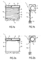
- the opening and closing device 1 may be a roller shutter, as illustrated in FIGS. Figures 1a, 2b, 2a and 2b . According to the illustrated example, it can be and a roller shutter comprising a winding drum 6 around which rolls a roll shutter apron.
- the drum is driven by a motor 5 for example tubular, in particular housed in the drum 6.
- the slides 10 are used to guide the deck blades.
- the roller shutter comprises between the upper end of the rolling shutter apron and the winding drum 6, an attachment lock, preventing, on the one hand, the fraudulent lifting of the deck in low position, allowing motor to lock when the apron reaches its bottom stop 3, as illustrated in figures 1 a and 2b in particular.
- the last blade of the roller shutter is also equipped with two stops 9 which cooperate with the upper stop 4, materialized by a trunk 8 of roller shutter.
- the method according to the invention can be implemented by a closing and opening device.
- This device comprises a movable member 2, means for actuating the movable member constituted by an electric motor 5, wire means for controlling the mobile member comprising at least one reversing switch, means for detecting the movement of the movable member, as well as logical processing means constituted by an electronic circuit for actuating the movable member and managing the limit switches.
- the device comprises, on the one hand, at least one programming mode of the limit switches, and on the other hand, at least one mode of actuation of the movable member during which the logic means of treatment cause the stop of the movable member when the limit switches are approached, or even reached, the device having means for triggering said at least one programming mode of the limit switches.
- the electrical wiring of the device is such that it provides a continuous supply of the electronic circuit and means for detecting the period of movement of the movable member, regardless of the state of the inverter switch.
- Said triggering means of said at least one end-of-stroke programming mode are constituted by the inverting switch as well as by the electronic circuit and more particularly state change detection means of the reversing switch.
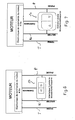
- FIGS. Figures 6 and 7 Three embodiments of a wiring according to the invention are respectively illustrated in FIGS. Figures 6 and 7 , to the Figures 8 and 9 , and Figures 10 and 11 .
- the embodiment of the Figures 6 and 7 is distinguished by a single control wire.
- the switch 20 (double or three positions) makes it possible to ensure an electrical contact, either between the phase line P and the control line, or between the neutral line N and the control line, to control the motor in one way or the other, or to allow no contact to keep the engine stopped.
- the control electronics more particularly the electronic circuit has means for detecting the phase and the neutral.
- the electronic circuit operates a relay to cause rotation of the motor in one direction.
- the electronic circuit actuates another relay to cause the rotation of the motor in the other direction.
- this example requires simple wiring, comprising at least three wires in the case of a single-phase system, if necessary four when the earth is necessary.
- Single-wire control wiring is also possible for a three-phase system.
- the embodiment of the Figures 8 and 9 is distinguished by two control wires.
- the inverter switch here makes it possible to ensure contact between the phase and the first control wire or between the phase and the second control wire or to allow no contact.
- the control electronics in particular the electronic circuit, have means for detecting the phase (P) either on the first control wire or on the second control wire. If the phase is detected on the first control wire, the logic processing means operates a relay to cause rotation of the motor in one direction. If the phase is detected on the second control wire, another relay is actuated and causes the rotation of the motor in the other direction. If no phase is detected, neither on the first wire nor on the second control wire, the motor remains at a standstill. It should be noted that two-wire wiring can also be used for a three-phase system.
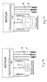
- the embodiment of the Figures 10 and 11 is distinguished by the presence of three control wires.
- these three son can be powered at very low voltage.
- One of the control wires can be supplied with DC voltage by the electronic circuit at a voltage V.
- the inverter switch provides electrical contact either between this wire and the control wire 1, or between this wire and the control wire 2, to respectively control the motor in one direction or the other through two relays, or in a position without contact (engine off).
- the electronic circuit has means for detecting the voltage V on the control wire 1 or the control wire 2. If the voltage V is detected on the control wire 1, a relay is actuated to cause the rotation of the motor in a first sense. If the voltage V is detected on the control wire 2, another relay is actuated to cause the rotation of the motor in the other direction.
- the method according to the invention can be implemented by a wire-controlled e-course management engine.
- Said motor comprises means for detecting the displacement of the rotor of said motor, as well as an electronic circuit for recording the limit switches and the management of said limit switches during the actuation of said motor.
- At least one phase line P and one neutral line N are provided for supplying said motor, as well as means for controlling the motor in one direction or the other, constituted by an inverting switch.
- the engine with electronic limit switches comprises, on the one hand, at least one mode of programming of the limit switches, and on the other hand, a normal mode of actuation of the movable member during which the electronic circuit causes the rotor to stop when the limit switches are approached or even reached.
- the motor has means for triggering said at least one programming mode of the limit switches.
- the phase line P and the neutral line N supply directly and permanently said electronic circuit as well as said means for detecting the displacement of the movable member, whatever the state of the inverter switch.
- the triggering means of said at least one programming mode of the limit switches are constituted by the inverter switch and by means of changeover state detection means of the inverter switch.
- the motor may have means for taking into account the displacement of the rotor whatever the state of the inverting switch 20. Also, a register is incremented or decremented in the case of the rotation of the rotor, even if the switch is in the off position.
- the inverter switch 20 may be a three-position switch or again, as illustrated in figure 7 , a double switch with two positions.
- the wiring differs from that of the state of the art in that it provides a continuous supply of the engine electronics, even when the inverter switch is in the "off" position.
- the double switch mechanically prohibits a simultaneous double connection between the neutral N and the control and secondly between the control and the phase P.
- the motor electronics do not detect any voltage on the control line. In this case, there is no electrical action on the motor windings.
- the electronic circuit detects either the neutral or the sector phase on the commanded line and operates the motor in one direction or the other depending on the line detected.
- the operating principle is similar for the example of the figure 7 , with a double switch. If no switch is actuated, the electronic circuit detects no voltage on the control line and does not operate the motor. Depending on the pressure on one or the other of the two switches, the electronic circuit detects either the phase line or the neutral line, and actuates the motor in one direction or the other depending on the detection.
Landscapes
- Engineering & Computer Science (AREA)
- Structural Engineering (AREA)
- Physics & Mathematics (AREA)
- General Physics & Mathematics (AREA)
- Automation & Control Theory (AREA)
- Architecture (AREA)
- Civil Engineering (AREA)
- Operating, Guiding And Securing Of Roll- Type Closing Members (AREA)
- Power-Operated Mechanisms For Wings (AREA)
Applications Claiming Priority (1)
| Application Number | Priority Date | Filing Date | Title |
|---|---|---|---|
| FR0801227A FR2928400B1 (fr) | 2008-03-06 | 2008-03-06 | Procede de commande d'un dispositif de fermeture et d'ouverture d'un ouvrant a commande filaire |
Publications (2)
| Publication Number | Publication Date |
|---|---|
| EP2098677A1 true EP2098677A1 (de) | 2009-09-09 |
| EP2098677B1 EP2098677B1 (de) | 2011-09-28 |
Family
ID=39971003
Family Applications (1)
| Application Number | Title | Priority Date | Filing Date |
|---|---|---|---|
| EP09370004A Active EP2098677B1 (de) | 2008-03-06 | 2009-03-05 | Verfahren zur Steuerung einer Schließ- und Öffnungsvorrichtung eines Öffnungselements mit Steuerung über Kabelverbindung |
Country Status (3)
| Country | Link |
|---|---|
| EP (1) | EP2098677B1 (de) |
| AT (1) | ATE526482T1 (de) |
| FR (1) | FR2928400B1 (de) |
Cited By (4)
| Publication number | Priority date | Publication date | Assignee | Title |
|---|---|---|---|---|
| FR2987158A1 (fr) * | 2012-02-20 | 2013-08-23 | Somfy Sas | Procede de fonctionnement d'une armoire de commande |
| EP2450523A3 (de) * | 2010-11-08 | 2014-08-20 | ARCA Beteiligungen GmbH | Antrieb für eine Verdunklungsvorrichtung |
| US20210063990A1 (en) * | 2019-08-26 | 2021-03-04 | Toyota Motor Engineering & Manufacturing North America, Inc. | Interface assemblies for manufacturing components |
| EP3783190A3 (de) * | 2019-08-16 | 2021-03-10 | Ningbo Sunfree Motor Technology Company Limited | Vorrichtung zur fernsteuerung eines vorhangs und ein verfahren zur einstellung von deren fernsteuerungshub |
Citations (5)
| Publication number | Priority date | Publication date | Assignee | Title |
|---|---|---|---|---|
| EP0439422A1 (de) * | 1990-01-26 | 1991-07-31 | Somfy | Sicherheitseinrichtung für motorisierte Rolladen |
| EP0744524A2 (de) * | 1995-05-24 | 1996-11-27 | Robert Bosch Gmbh | Vorrichtung zur elektronischen Steuerung der Bewegungen eines Rolladens |
| US6078159A (en) | 1999-02-17 | 2000-06-20 | The Chamberlain Group, Inc. | Method and apparatus for programming a logic board from switching power |
| EP1626154A1 (de) * | 2004-08-10 | 2006-02-15 | Somfy SAS | Verfahren zum Betrieb eines aus einer Drahtschnittstelle gesteuerten und versorgten Rollladens |
| DE102004041293A1 (de) * | 2004-08-25 | 2006-03-09 | Provita Gmbh | Vorrichtung zur elektronischen Steuerung der Auf- und Abbewegung eines Rollladens oder dergleichen |
Family Cites Families (1)
| Publication number | Priority date | Publication date | Assignee | Title |
|---|---|---|---|---|
| FR2874291B1 (fr) * | 2004-08-10 | 2006-11-17 | Somfy Sas | Actonneur electrique de volet roulant presentant une interface de commande munie de contacts electriques a ouverture |
-
2008
- 2008-03-06 FR FR0801227A patent/FR2928400B1/fr active Active
-
2009
- 2009-03-05 AT AT09370004T patent/ATE526482T1/de not_active IP Right Cessation
- 2009-03-05 EP EP09370004A patent/EP2098677B1/de active Active
Patent Citations (5)
| Publication number | Priority date | Publication date | Assignee | Title |
|---|---|---|---|---|
| EP0439422A1 (de) * | 1990-01-26 | 1991-07-31 | Somfy | Sicherheitseinrichtung für motorisierte Rolladen |
| EP0744524A2 (de) * | 1995-05-24 | 1996-11-27 | Robert Bosch Gmbh | Vorrichtung zur elektronischen Steuerung der Bewegungen eines Rolladens |
| US6078159A (en) | 1999-02-17 | 2000-06-20 | The Chamberlain Group, Inc. | Method and apparatus for programming a logic board from switching power |
| EP1626154A1 (de) * | 2004-08-10 | 2006-02-15 | Somfy SAS | Verfahren zum Betrieb eines aus einer Drahtschnittstelle gesteuerten und versorgten Rollladens |
| DE102004041293A1 (de) * | 2004-08-25 | 2006-03-09 | Provita Gmbh | Vorrichtung zur elektronischen Steuerung der Auf- und Abbewegung eines Rollladens oder dergleichen |
Cited By (6)
| Publication number | Priority date | Publication date | Assignee | Title |
|---|---|---|---|---|
| EP2450523A3 (de) * | 2010-11-08 | 2014-08-20 | ARCA Beteiligungen GmbH | Antrieb für eine Verdunklungsvorrichtung |
| FR2987158A1 (fr) * | 2012-02-20 | 2013-08-23 | Somfy Sas | Procede de fonctionnement d'une armoire de commande |
| EP2629274A3 (de) * | 2012-02-20 | 2014-05-21 | Somfy SAS | Funktionsverfahren eines Schaltschranks |
| EP3783190A3 (de) * | 2019-08-16 | 2021-03-10 | Ningbo Sunfree Motor Technology Company Limited | Vorrichtung zur fernsteuerung eines vorhangs und ein verfahren zur einstellung von deren fernsteuerungshub |
| US20210063990A1 (en) * | 2019-08-26 | 2021-03-04 | Toyota Motor Engineering & Manufacturing North America, Inc. | Interface assemblies for manufacturing components |
| US11650562B2 (en) * | 2019-08-26 | 2023-05-16 | Toyota Motor Engineering & Manufacturing North America, Inc. | Interface assemblies for manufacturing components |
Also Published As
| Publication number | Publication date |
|---|---|
| ATE526482T1 (de) | 2011-10-15 |
| EP2098677B1 (de) | 2011-09-28 |
| FR2928400B1 (fr) | 2011-10-28 |
| FR2928400A1 (fr) | 2009-09-11 |
Similar Documents
| Publication | Publication Date | Title |
|---|---|---|
| EP0426577B1 (de) | Verfahren und Vorrichtung zum Verstellen einer Verdunkelungsanordnung in justierbaren Positionen und Installation zur Durchführung der Anmeldung | |
| EP1510649A1 (de) | Verfahren zur Initialisierung eines Rollladens | |
| FR2680437A1 (fr) | Montage pour surveiller des elements de fermeture entraines par un moteur electrique. | |
| EP2098677B1 (de) | Verfahren zur Steuerung einer Schließ- und Öffnungsvorrichtung eines Öffnungselements mit Steuerung über Kabelverbindung | |
| FR2925932A1 (fr) | Procede de reglage d'une installation de protection solaire motorisee ne comprenant pas de butee franche. | |
| EP1508844A1 (de) | Verfahren zur Initialisierung eines motorisierten Rolladens | |
| JP2004038945A (ja) | ローラブラインドアクチュエータの走行限界を学習する方法 | |
| EP1446548B1 (de) | Verfahren zum abstimmen auf den gegebenen richtungsbefehl eines elektromotors in einer verschlussanlage oder dergleichen wie zum beispiel einem rollladen | |
| FR2740552A1 (fr) | Procede pour controler le trajet de deplacement d'une piece | |
| EP0502773B1 (de) | Steuerungsanordnung für einen Motor, insbesondere für den Antrieb von Aufzugstüren | |
| EP2808479B1 (de) | Verfahren und Vorrichtung zur Betätigung eines mobilen Verschluss-, Verdunkelungs-, Sonnenschutz- oder Leinwandelements | |
| EP3121364B1 (de) | Verfahren zur steuerung eines stellglieds eines aufrollbaren behangs, und system, bei dem dieses verfahren umgesetzt wird | |
| EP3177797B1 (de) | Verfahren zur steuerung des betriebs einer motorisierten antriebsvorrichtung für eine anlage im bereich der haustechnik und mit dem verfahren betriebene motorisierte antriebsvorrichtung | |
| FR2928401A1 (fr) | Procede de commande d'un dispositif de fermeture et d'ouverture a commande filaire, tel que notamment un volet roulant | |
| EP3470616B1 (de) | Verfahren zur automatischen regulierung einer mit einem blockiersystem ausgestatteten rollladenanlage | |
| EP1541798B1 (de) | Lernverfahren für einen motorisierten Verschluss und und Vorrichtung zur Ausführung dieses Verfahrens | |
| EP2099126B1 (de) | Motor mit elektronischer Steuerung der Endschalter | |
| EP1160415B1 (de) | Steuerung für motorisierte Verdunkelungsvorrichtungen mit Programmwahl | |
| EP2098935A2 (de) | Motor mit elektronischer Steuerung der Endschalter und Einbauverfahren einer Öffnungs- und Schließvorrichtung, wie insbesondere für ein Rollo, das einen solchen Motor umfasst | |
| EP1154121B1 (de) | Perfektionierte Steuerung für motorgetriebene Verdunkelungsvorrichtungen | |
| FR2741651A1 (fr) | Dispositif assurant l'arret automatique et la synchronisation de volets battants motorises a l'ouverture et a la fermeture | |
| EP3205810A1 (de) | Gerät zur fernsteuerung von vorrichtungen zum verschluss von gebäudeöffnungen vom typ jalousie oder klappladen | |
| EP3597848B1 (de) | Steuerungsverfahren von hindernissen in einer anlage, die die bewegungen von öffnungsflügeln oder klappläden kontrolliert | |
| EP3514307A1 (de) | Management der kombinierten bewegung von zwei motorisierten öffnungsflügeln für den fall, das einer der beiden flügel auf ein hindernis trifft | |
| EP3473792A1 (de) | Vorrichtung zum hydraulischen verschliessen einer schliessvorrichtung mit elektrischer öffnung, und mit einer solchen vorrichtung ausgestattete schliessvorrichtung |
Legal Events
| Date | Code | Title | Description |
|---|---|---|---|
| PUAI | Public reference made under article 153(3) epc to a published international application that has entered the european phase |
Free format text: ORIGINAL CODE: 0009012 |
|
| AK | Designated contracting states |
Kind code of ref document: A1 Designated state(s): AT BE BG CH CY CZ DE DK EE ES FI FR GB GR HR HU IE IS IT LI LT LU LV MC MK MT NL NO PL PT RO SE SI SK TR |
|
| AX | Request for extension of the european patent |
Extension state: AL BA RS |
|
| 17P | Request for examination filed |
Effective date: 20100305 |
|
| 17Q | First examination report despatched |
Effective date: 20100330 |
|
| AKX | Designation fees paid |
Designated state(s): AT BE BG CH CY CZ DE DK EE ES FI FR GB GR HR HU IE IS IT LI LT LU LV MC MK MT NL NO PL PT RO SE SI SK TR |
|
| GRAP | Despatch of communication of intention to grant a patent |
Free format text: ORIGINAL CODE: EPIDOSNIGR1 |
|
| GRAS | Grant fee paid |
Free format text: ORIGINAL CODE: EPIDOSNIGR3 |
|
| GRAA | (expected) grant |
Free format text: ORIGINAL CODE: 0009210 |
|
| AK | Designated contracting states |
Kind code of ref document: B1 Designated state(s): AT BE BG CH CY CZ DE DK EE ES FI FR GB GR HR HU IE IS IT LI LT LU LV MC MK MT NL NO PL PT RO SE SI SK TR |
|
| REG | Reference to a national code |
Ref country code: GB Ref legal event code: FG4D Free format text: NOT ENGLISH |
|
| REG | Reference to a national code |
Ref country code: CH Ref legal event code: EP |
|
| REG | Reference to a national code |
Ref country code: IE Ref legal event code: FG4D |
|
| REG | Reference to a national code |
Ref country code: DE Ref legal event code: R096 Ref document number: 602009002832 Country of ref document: DE Effective date: 20111124 |
|
| RAP2 | Party data changed (patent owner data changed or rights of a patent transferred) |
Owner name: DEPRAT JEAN SA |
|
| REG | Reference to a national code |
Ref country code: NL Ref legal event code: VDEP Effective date: 20110928 |
|
| PG25 | Lapsed in a contracting state [announced via postgrant information from national office to epo] |
Ref country code: LT Free format text: LAPSE BECAUSE OF FAILURE TO SUBMIT A TRANSLATION OF THE DESCRIPTION OR TO PAY THE FEE WITHIN THE PRESCRIBED TIME-LIMIT Effective date: 20110928 Ref country code: HR Free format text: LAPSE BECAUSE OF FAILURE TO SUBMIT A TRANSLATION OF THE DESCRIPTION OR TO PAY THE FEE WITHIN THE PRESCRIBED TIME-LIMIT Effective date: 20110928 Ref country code: NO Free format text: LAPSE BECAUSE OF FAILURE TO SUBMIT A TRANSLATION OF THE DESCRIPTION OR TO PAY THE FEE WITHIN THE PRESCRIBED TIME-LIMIT Effective date: 20111228 Ref country code: FI Free format text: LAPSE BECAUSE OF FAILURE TO SUBMIT A TRANSLATION OF THE DESCRIPTION OR TO PAY THE FEE WITHIN THE PRESCRIBED TIME-LIMIT Effective date: 20110928 Ref country code: SE Free format text: LAPSE BECAUSE OF FAILURE TO SUBMIT A TRANSLATION OF THE DESCRIPTION OR TO PAY THE FEE WITHIN THE PRESCRIBED TIME-LIMIT Effective date: 20110928 |
|
| LTIE | Lt: invalidation of european patent or patent extension |
Effective date: 20110928 |
|
| PG25 | Lapsed in a contracting state [announced via postgrant information from national office to epo] |
Ref country code: AT Free format text: LAPSE BECAUSE OF FAILURE TO SUBMIT A TRANSLATION OF THE DESCRIPTION OR TO PAY THE FEE WITHIN THE PRESCRIBED TIME-LIMIT Effective date: 20110928 Ref country code: GR Free format text: LAPSE BECAUSE OF FAILURE TO SUBMIT A TRANSLATION OF THE DESCRIPTION OR TO PAY THE FEE WITHIN THE PRESCRIBED TIME-LIMIT Effective date: 20111229 Ref country code: LV Free format text: LAPSE BECAUSE OF FAILURE TO SUBMIT A TRANSLATION OF THE DESCRIPTION OR TO PAY THE FEE WITHIN THE PRESCRIBED TIME-LIMIT Effective date: 20110928 Ref country code: SI Free format text: LAPSE BECAUSE OF FAILURE TO SUBMIT A TRANSLATION OF THE DESCRIPTION OR TO PAY THE FEE WITHIN THE PRESCRIBED TIME-LIMIT Effective date: 20110928 Ref country code: CY Free format text: LAPSE BECAUSE OF FAILURE TO SUBMIT A TRANSLATION OF THE DESCRIPTION OR TO PAY THE FEE WITHIN THE PRESCRIBED TIME-LIMIT Effective date: 20110928 |
|
| REG | Reference to a national code |
Ref country code: AT Ref legal event code: MK05 Ref document number: 526482 Country of ref document: AT Kind code of ref document: T Effective date: 20110928 |
|
| REG | Reference to a national code |
Ref country code: IE Ref legal event code: FD4D |
|
| PG25 | Lapsed in a contracting state [announced via postgrant information from national office to epo] |
Ref country code: SK Free format text: LAPSE BECAUSE OF FAILURE TO SUBMIT A TRANSLATION OF THE DESCRIPTION OR TO PAY THE FEE WITHIN THE PRESCRIBED TIME-LIMIT Effective date: 20110928 Ref country code: IS Free format text: LAPSE BECAUSE OF FAILURE TO SUBMIT A TRANSLATION OF THE DESCRIPTION OR TO PAY THE FEE WITHIN THE PRESCRIBED TIME-LIMIT Effective date: 20120128 Ref country code: CZ Free format text: LAPSE BECAUSE OF FAILURE TO SUBMIT A TRANSLATION OF THE DESCRIPTION OR TO PAY THE FEE WITHIN THE PRESCRIBED TIME-LIMIT Effective date: 20110928 |
|
| PG25 | Lapsed in a contracting state [announced via postgrant information from national office to epo] |
Ref country code: NL Free format text: LAPSE BECAUSE OF FAILURE TO SUBMIT A TRANSLATION OF THE DESCRIPTION OR TO PAY THE FEE WITHIN THE PRESCRIBED TIME-LIMIT Effective date: 20110928 Ref country code: RO Free format text: LAPSE BECAUSE OF FAILURE TO SUBMIT A TRANSLATION OF THE DESCRIPTION OR TO PAY THE FEE WITHIN THE PRESCRIBED TIME-LIMIT Effective date: 20110928 Ref country code: PT Free format text: LAPSE BECAUSE OF FAILURE TO SUBMIT A TRANSLATION OF THE DESCRIPTION OR TO PAY THE FEE WITHIN THE PRESCRIBED TIME-LIMIT Effective date: 20120130 Ref country code: EE Free format text: LAPSE BECAUSE OF FAILURE TO SUBMIT A TRANSLATION OF THE DESCRIPTION OR TO PAY THE FEE WITHIN THE PRESCRIBED TIME-LIMIT Effective date: 20110928 |
|
| PG25 | Lapsed in a contracting state [announced via postgrant information from national office to epo] |
Ref country code: IE Free format text: LAPSE BECAUSE OF FAILURE TO SUBMIT A TRANSLATION OF THE DESCRIPTION OR TO PAY THE FEE WITHIN THE PRESCRIBED TIME-LIMIT Effective date: 20110928 Ref country code: DK Free format text: LAPSE BECAUSE OF FAILURE TO SUBMIT A TRANSLATION OF THE DESCRIPTION OR TO PAY THE FEE WITHIN THE PRESCRIBED TIME-LIMIT Effective date: 20110928 |
|
| PLBE | No opposition filed within time limit |
Free format text: ORIGINAL CODE: 0009261 |
|
| STAA | Information on the status of an ep patent application or granted ep patent |
Free format text: STATUS: NO OPPOSITION FILED WITHIN TIME LIMIT |
|
| PG25 | Lapsed in a contracting state [announced via postgrant information from national office to epo] |
Ref country code: PL Free format text: LAPSE BECAUSE OF FAILURE TO SUBMIT A TRANSLATION OF THE DESCRIPTION OR TO PAY THE FEE WITHIN THE PRESCRIBED TIME-LIMIT Effective date: 20110928 |
|
| 26N | No opposition filed |
Effective date: 20120629 |
|
| REG | Reference to a national code |
Ref country code: DE Ref legal event code: R097 Ref document number: 602009002832 Country of ref document: DE Effective date: 20120629 |
|
| PG25 | Lapsed in a contracting state [announced via postgrant information from national office to epo] |
Ref country code: MC Free format text: LAPSE BECAUSE OF NON-PAYMENT OF DUE FEES Effective date: 20120331 |
|
| PG25 | Lapsed in a contracting state [announced via postgrant information from national office to epo] |
Ref country code: MK Free format text: LAPSE BECAUSE OF FAILURE TO SUBMIT A TRANSLATION OF THE DESCRIPTION OR TO PAY THE FEE WITHIN THE PRESCRIBED TIME-LIMIT Effective date: 20110928 |
|
| PG25 | Lapsed in a contracting state [announced via postgrant information from national office to epo] |
Ref country code: ES Free format text: LAPSE BECAUSE OF FAILURE TO SUBMIT A TRANSLATION OF THE DESCRIPTION OR TO PAY THE FEE WITHIN THE PRESCRIBED TIME-LIMIT Effective date: 20120108 |
|
| PG25 | Lapsed in a contracting state [announced via postgrant information from national office to epo] |
Ref country code: BG Free format text: LAPSE BECAUSE OF FAILURE TO SUBMIT A TRANSLATION OF THE DESCRIPTION OR TO PAY THE FEE WITHIN THE PRESCRIBED TIME-LIMIT Effective date: 20111228 |
|
| PG25 | Lapsed in a contracting state [announced via postgrant information from national office to epo] |
Ref country code: MT Free format text: LAPSE BECAUSE OF FAILURE TO SUBMIT A TRANSLATION OF THE DESCRIPTION OR TO PAY THE FEE WITHIN THE PRESCRIBED TIME-LIMIT Effective date: 20110928 |
|
| REG | Reference to a national code |
Ref country code: CH Ref legal event code: PL |
|
| GBPC | Gb: european patent ceased through non-payment of renewal fee |
Effective date: 20130305 |
|
| PG25 | Lapsed in a contracting state [announced via postgrant information from national office to epo] |
Ref country code: GB Free format text: LAPSE BECAUSE OF NON-PAYMENT OF DUE FEES Effective date: 20130305 Ref country code: CH Free format text: LAPSE BECAUSE OF NON-PAYMENT OF DUE FEES Effective date: 20130331 Ref country code: LI Free format text: LAPSE BECAUSE OF NON-PAYMENT OF DUE FEES Effective date: 20130331 |
|
| PG25 | Lapsed in a contracting state [announced via postgrant information from national office to epo] |
Ref country code: TR Free format text: LAPSE BECAUSE OF FAILURE TO SUBMIT A TRANSLATION OF THE DESCRIPTION OR TO PAY THE FEE WITHIN THE PRESCRIBED TIME-LIMIT Effective date: 20110928 |
|
| PG25 | Lapsed in a contracting state [announced via postgrant information from national office to epo] |
Ref country code: LU Free format text: LAPSE BECAUSE OF NON-PAYMENT OF DUE FEES Effective date: 20120305 |
|
| PG25 | Lapsed in a contracting state [announced via postgrant information from national office to epo] |
Ref country code: HU Free format text: LAPSE BECAUSE OF FAILURE TO SUBMIT A TRANSLATION OF THE DESCRIPTION OR TO PAY THE FEE WITHIN THE PRESCRIBED TIME-LIMIT Effective date: 20090305 |
|
| REG | Reference to a national code |
Ref country code: FR Ref legal event code: PLFP Year of fee payment: 8 |
|
| PGFP | Annual fee paid to national office [announced via postgrant information from national office to epo] |
Ref country code: DE Payment date: 20160316 Year of fee payment: 8 |
|
| PGFP | Annual fee paid to national office [announced via postgrant information from national office to epo] |
Ref country code: IT Payment date: 20160318 Year of fee payment: 8 Ref country code: BE Payment date: 20160330 Year of fee payment: 8 |
|
| REG | Reference to a national code |
Ref country code: FR Ref legal event code: PLFP Year of fee payment: 9 |
|
| REG | Reference to a national code |
Ref country code: DE Ref legal event code: R119 Ref document number: 602009002832 Country of ref document: DE |
|
| PG25 | Lapsed in a contracting state [announced via postgrant information from national office to epo] |
Ref country code: DE Free format text: LAPSE BECAUSE OF NON-PAYMENT OF DUE FEES Effective date: 20171003 |
|
| PG25 | Lapsed in a contracting state [announced via postgrant information from national office to epo] |
Ref country code: IT Free format text: LAPSE BECAUSE OF NON-PAYMENT OF DUE FEES Effective date: 20170305 |
|
| REG | Reference to a national code |
Ref country code: BE Ref legal event code: MM Effective date: 20170331 |
|
| REG | Reference to a national code |
Ref country code: FR Ref legal event code: PLFP Year of fee payment: 10 |
|
| PG25 | Lapsed in a contracting state [announced via postgrant information from national office to epo] |
Ref country code: BE Free format text: LAPSE BECAUSE OF NON-PAYMENT OF DUE FEES Effective date: 20170331 |
|
| PGFP | Annual fee paid to national office [announced via postgrant information from national office to epo] |
Ref country code: FR Payment date: 20260115 Year of fee payment: 18 |