EP2098671A1 - Kraftfahrzeug mit einem automatisch in eine Offen- und eine Schließstellung verstellbaren Fahrzeugteil - Google Patents
Kraftfahrzeug mit einem automatisch in eine Offen- und eine Schließstellung verstellbaren Fahrzeugteil Download PDFInfo
- Publication number
- EP2098671A1 EP2098671A1 EP08102249A EP08102249A EP2098671A1 EP 2098671 A1 EP2098671 A1 EP 2098671A1 EP 08102249 A EP08102249 A EP 08102249A EP 08102249 A EP08102249 A EP 08102249A EP 2098671 A1 EP2098671 A1 EP 2098671A1
- Authority
- EP
- European Patent Office
- Prior art keywords
- motor vehicle
- detection device
- proximity sensor
- vehicle
- body part
- Prior art date
- Legal status (The legal status is an assumption and is not a legal conclusion. Google has not performed a legal analysis and makes no representation as to the accuracy of the status listed.)
- Granted
Links
Images



Classifications
-
- B—PERFORMING OPERATIONS; TRANSPORTING
- B60—VEHICLES IN GENERAL
- B60R—VEHICLES, VEHICLE FITTINGS, OR VEHICLE PARTS, NOT OTHERWISE PROVIDED FOR
- B60R25/00—Fittings or systems for preventing or indicating unauthorised use or theft of vehicles
- B60R25/20—Means to switch the anti-theft system on or off
- B60R25/24—Means to switch the anti-theft system on or off using electronic identifiers containing a code not memorised by the user
- B60R25/246—Means to switch the anti-theft system on or off using electronic identifiers containing a code not memorised by the user characterised by the challenge triggering
-
- B—PERFORMING OPERATIONS; TRANSPORTING
- B60—VEHICLES IN GENERAL
- B60R—VEHICLES, VEHICLE FITTINGS, OR VEHICLE PARTS, NOT OTHERWISE PROVIDED FOR
- B60R25/00—Fittings or systems for preventing or indicating unauthorised use or theft of vehicles
- B60R25/20—Means to switch the anti-theft system on or off
- B60R25/2054—Means to switch the anti-theft system on or off by foot gestures
-
- E—FIXED CONSTRUCTIONS
- E05—LOCKS; KEYS; WINDOW OR DOOR FITTINGS; SAFES
- E05F—DEVICES FOR MOVING WINGS INTO OPEN OR CLOSED POSITION; CHECKS FOR WINGS; WING FITTINGS NOT OTHERWISE PROVIDED FOR, CONCERNED WITH THE FUNCTIONING OF THE WING
- E05F15/00—Power-operated mechanisms for wings
- E05F15/70—Power-operated mechanisms for wings with automatic actuation
- E05F15/73—Power-operated mechanisms for wings with automatic actuation responsive to movement or presence of persons or objects
- E05F15/76—Power-operated mechanisms for wings with automatic actuation responsive to movement or presence of persons or objects responsive to devices carried by persons or objects, e.g. magnets or reflectors
-
- G—PHYSICS
- G07—CHECKING-DEVICES
- G07C—TIME OR ATTENDANCE REGISTERS; REGISTERING OR INDICATING THE WORKING OF MACHINES; GENERATING RANDOM NUMBERS; VOTING OR LOTTERY APPARATUS; ARRANGEMENTS, SYSTEMS OR APPARATUS FOR CHECKING NOT PROVIDED FOR ELSEWHERE
- G07C9/00—Individual registration on entry or exit
- G07C9/00174—Electronically operated locks; Circuits therefor; Nonmechanical keys therefor, e.g. passive or active electrical keys or other data carriers without mechanical keys
- G07C9/00309—Electronically operated locks; Circuits therefor; Nonmechanical keys therefor, e.g. passive or active electrical keys or other data carriers without mechanical keys operated with bidirectional data transmission between data carrier and locks
-
- E—FIXED CONSTRUCTIONS
- E05—LOCKS; KEYS; WINDOW OR DOOR FITTINGS; SAFES
- E05F—DEVICES FOR MOVING WINGS INTO OPEN OR CLOSED POSITION; CHECKS FOR WINGS; WING FITTINGS NOT OTHERWISE PROVIDED FOR, CONCERNED WITH THE FUNCTIONING OF THE WING
- E05F15/00—Power-operated mechanisms for wings
-
- E—FIXED CONSTRUCTIONS
- E05—LOCKS; KEYS; WINDOW OR DOOR FITTINGS; SAFES
- E05F—DEVICES FOR MOVING WINGS INTO OPEN OR CLOSED POSITION; CHECKS FOR WINGS; WING FITTINGS NOT OTHERWISE PROVIDED FOR, CONCERNED WITH THE FUNCTIONING OF THE WING
- E05F15/00—Power-operated mechanisms for wings
- E05F15/70—Power-operated mechanisms for wings with automatic actuation
- E05F15/73—Power-operated mechanisms for wings with automatic actuation responsive to movement or presence of persons or objects
-
- E—FIXED CONSTRUCTIONS
- E05—LOCKS; KEYS; WINDOW OR DOOR FITTINGS; SAFES
- E05Y—INDEXING SCHEME ASSOCIATED WITH SUBCLASSES E05D AND E05F, RELATING TO CONSTRUCTION ELEMENTS, ELECTRIC CONTROL, POWER SUPPLY, POWER SIGNAL OR TRANSMISSION, USER INTERFACES, MOUNTING OR COUPLING, DETAILS, ACCESSORIES, AUXILIARY OPERATIONS NOT OTHERWISE PROVIDED FOR, APPLICATION THEREOF
- E05Y2201/00—Constructional elements; Accessories therefor
- E05Y2201/60—Suspension or transmission members; Accessories therefor
- E05Y2201/622—Suspension or transmission members elements
- E05Y2201/676—Transmission of human force
- E05Y2201/68—Handles, cranks
-
- E—FIXED CONSTRUCTIONS
- E05—LOCKS; KEYS; WINDOW OR DOOR FITTINGS; SAFES
- E05Y—INDEXING SCHEME ASSOCIATED WITH SUBCLASSES E05D AND E05F, RELATING TO CONSTRUCTION ELEMENTS, ELECTRIC CONTROL, POWER SUPPLY, POWER SIGNAL OR TRANSMISSION, USER INTERFACES, MOUNTING OR COUPLING, DETAILS, ACCESSORIES, AUXILIARY OPERATIONS NOT OTHERWISE PROVIDED FOR, APPLICATION THEREOF
- E05Y2400/00—Electronic control; Electrical power; Power supply; Power or signal transmission; User interfaces
- E05Y2400/10—Electronic control
- E05Y2400/45—Control modes
- E05Y2400/452—Control modes for saving energy, e.g. sleep or wake-up
-
- E—FIXED CONSTRUCTIONS
- E05—LOCKS; KEYS; WINDOW OR DOOR FITTINGS; SAFES
- E05Y—INDEXING SCHEME ASSOCIATED WITH SUBCLASSES E05D AND E05F, RELATING TO CONSTRUCTION ELEMENTS, ELECTRIC CONTROL, POWER SUPPLY, POWER SIGNAL OR TRANSMISSION, USER INTERFACES, MOUNTING OR COUPLING, DETAILS, ACCESSORIES, AUXILIARY OPERATIONS NOT OTHERWISE PROVIDED FOR, APPLICATION THEREOF
- E05Y2400/00—Electronic control; Electrical power; Power supply; Power or signal transmission; User interfaces
- E05Y2400/80—User interfaces
- E05Y2400/85—User input means
- E05Y2400/852—Sensors
-
- E—FIXED CONSTRUCTIONS
- E05—LOCKS; KEYS; WINDOW OR DOOR FITTINGS; SAFES
- E05Y—INDEXING SCHEME ASSOCIATED WITH SUBCLASSES E05D AND E05F, RELATING TO CONSTRUCTION ELEMENTS, ELECTRIC CONTROL, POWER SUPPLY, POWER SIGNAL OR TRANSMISSION, USER INTERFACES, MOUNTING OR COUPLING, DETAILS, ACCESSORIES, AUXILIARY OPERATIONS NOT OTHERWISE PROVIDED FOR, APPLICATION THEREOF
- E05Y2400/00—Electronic control; Electrical power; Power supply; Power or signal transmission; User interfaces
- E05Y2400/80—User interfaces
- E05Y2400/85—User input means
- E05Y2400/852—Sensors
- E05Y2400/854—Switches
-
- E—FIXED CONSTRUCTIONS
- E05—LOCKS; KEYS; WINDOW OR DOOR FITTINGS; SAFES
- E05Y—INDEXING SCHEME ASSOCIATED WITH SUBCLASSES E05D AND E05F, RELATING TO CONSTRUCTION ELEMENTS, ELECTRIC CONTROL, POWER SUPPLY, POWER SIGNAL OR TRANSMISSION, USER INTERFACES, MOUNTING OR COUPLING, DETAILS, ACCESSORIES, AUXILIARY OPERATIONS NOT OTHERWISE PROVIDED FOR, APPLICATION THEREOF
- E05Y2400/00—Electronic control; Electrical power; Power supply; Power or signal transmission; User interfaces
- E05Y2400/80—User interfaces
- E05Y2400/85—User input means
- E05Y2400/856—Actuation thereof
- E05Y2400/858—Actuation thereof by body parts, e.g. by feet
-
- E—FIXED CONSTRUCTIONS
- E05—LOCKS; KEYS; WINDOW OR DOOR FITTINGS; SAFES
- E05Y—INDEXING SCHEME ASSOCIATED WITH SUBCLASSES E05D AND E05F, RELATING TO CONSTRUCTION ELEMENTS, ELECTRIC CONTROL, POWER SUPPLY, POWER SIGNAL OR TRANSMISSION, USER INTERFACES, MOUNTING OR COUPLING, DETAILS, ACCESSORIES, AUXILIARY OPERATIONS NOT OTHERWISE PROVIDED FOR, APPLICATION THEREOF
- E05Y2400/00—Electronic control; Electrical power; Power supply; Power or signal transmission; User interfaces
- E05Y2400/80—User interfaces
- E05Y2400/85—User input means
- E05Y2400/856—Actuation thereof
- E05Y2400/858—Actuation thereof by body parts, e.g. by feet
- E05Y2400/86—Actuation thereof by body parts, e.g. by feet by hand
-
- E—FIXED CONSTRUCTIONS
- E05—LOCKS; KEYS; WINDOW OR DOOR FITTINGS; SAFES
- E05Y—INDEXING SCHEME ASSOCIATED WITH SUBCLASSES E05D AND E05F, RELATING TO CONSTRUCTION ELEMENTS, ELECTRIC CONTROL, POWER SUPPLY, POWER SIGNAL OR TRANSMISSION, USER INTERFACES, MOUNTING OR COUPLING, DETAILS, ACCESSORIES, AUXILIARY OPERATIONS NOT OTHERWISE PROVIDED FOR, APPLICATION THEREOF
- E05Y2800/00—Details, accessories and auxiliary operations not otherwise provided for
- E05Y2800/40—Physical or chemical protection
-
- E—FIXED CONSTRUCTIONS
- E05—LOCKS; KEYS; WINDOW OR DOOR FITTINGS; SAFES
- E05Y—INDEXING SCHEME ASSOCIATED WITH SUBCLASSES E05D AND E05F, RELATING TO CONSTRUCTION ELEMENTS, ELECTRIC CONTROL, POWER SUPPLY, POWER SIGNAL OR TRANSMISSION, USER INTERFACES, MOUNTING OR COUPLING, DETAILS, ACCESSORIES, AUXILIARY OPERATIONS NOT OTHERWISE PROVIDED FOR, APPLICATION THEREOF
- E05Y2900/00—Application of doors, windows, wings or fittings thereof
- E05Y2900/50—Application of doors, windows, wings or fittings thereof for vehicles
- E05Y2900/53—Type of wing
- E05Y2900/546—Tailboards, tailgates or sideboards opening upwards
-
- G—PHYSICS
- G07—CHECKING-DEVICES
- G07C—TIME OR ATTENDANCE REGISTERS; REGISTERING OR INDICATING THE WORKING OF MACHINES; GENERATING RANDOM NUMBERS; VOTING OR LOTTERY APPARATUS; ARRANGEMENTS, SYSTEMS OR APPARATUS FOR CHECKING NOT PROVIDED FOR ELSEWHERE
- G07C9/00—Individual registration on entry or exit
- G07C9/00174—Electronically operated locks; Circuits therefor; Nonmechanical keys therefor, e.g. passive or active electrical keys or other data carriers without mechanical keys
- G07C9/00309—Electronically operated locks; Circuits therefor; Nonmechanical keys therefor, e.g. passive or active electrical keys or other data carriers without mechanical keys operated with bidirectional data transmission between data carrier and locks
- G07C2009/00507—Electronically operated locks; Circuits therefor; Nonmechanical keys therefor, e.g. passive or active electrical keys or other data carriers without mechanical keys operated with bidirectional data transmission between data carrier and locks keyless data carrier having more than one function
- G07C2009/00523—Electronically operated locks; Circuits therefor; Nonmechanical keys therefor, e.g. passive or active electrical keys or other data carriers without mechanical keys operated with bidirectional data transmission between data carrier and locks keyless data carrier having more than one function opening of different locks separately
-
- G—PHYSICS
- G07—CHECKING-DEVICES
- G07C—TIME OR ATTENDANCE REGISTERS; REGISTERING OR INDICATING THE WORKING OF MACHINES; GENERATING RANDOM NUMBERS; VOTING OR LOTTERY APPARATUS; ARRANGEMENTS, SYSTEMS OR APPARATUS FOR CHECKING NOT PROVIDED FOR ELSEWHERE
- G07C2209/00—Indexing scheme relating to groups G07C9/00 - G07C9/38
- G07C2209/60—Indexing scheme relating to groups G07C9/00174 - G07C9/00944
- G07C2209/63—Comprising locating means for detecting the position of the data carrier, i.e. within the vehicle or within a certain distance from the vehicle
-
- G—PHYSICS
- G07—CHECKING-DEVICES
- G07C—TIME OR ATTENDANCE REGISTERS; REGISTERING OR INDICATING THE WORKING OF MACHINES; GENERATING RANDOM NUMBERS; VOTING OR LOTTERY APPARATUS; ARRANGEMENTS, SYSTEMS OR APPARATUS FOR CHECKING NOT PROVIDED FOR ELSEWHERE
- G07C2209/00—Indexing scheme relating to groups G07C9/00 - G07C9/38
- G07C2209/60—Indexing scheme relating to groups G07C9/00174 - G07C9/00944
- G07C2209/63—Comprising locating means for detecting the position of the data carrier, i.e. within the vehicle or within a certain distance from the vehicle
- G07C2209/64—Comprising locating means for detecting the position of the data carrier, i.e. within the vehicle or within a certain distance from the vehicle using a proximity sensor
Definitions
- the invention relates to a motor vehicle with at least one adjustable in an open and a closed position vehicle part, in particular a tailgate and / or a vehicle door, with an actuating device for automatically adjusting the vehicle part between the open and the closed position, with a proximity sensor, a part an outside area of the motor vehicle is monitored for the presence of a body part of a user, with an access authorization means and a detection device, by means of which the presence of the access authorization means is detectable without contact in a surrounding area of the detection device, with a control device connected to the proximity sensor, the detection device and the actuating device is configured such that an actuating control signal triggering the adjustment of the vehicle part is generated when the proximity sensor detects the presence of the body part in the vehicle body Part of the outdoor area and the detection device to detect the presence of the access authorization means in the surrounding area, and wherein the control device is connected to a switching device for switching on and off of the detection device.
- a vehicle part is understood in particular to mean a swinging door, a hinged door,
- Such a motor vehicle which has several doors and a tailgate, is off DE 10 2004 0471 709 B3 known.
- the tailgate of the vehicle has an actuating device with which it can be automatically adjusted to the open position due to an opening command from its closed position.
- the motor vehicle has a user-carried access authorization means, such as an intelligent vehicle key or a key card, which cooperates with a detection device located in the motor vehicle. With the aid of the detection device, the presence of the access authorization means in a predetermined surrounding area of the motor vehicle can be checked.
- the motor vehicle has a proximity sensor which has two sensor elements in the rear region of the motor vehicle below a bumper.
- the proximity sensor and the detection device are in control connection with a control device such that the proximity sensor is switched on when the detection device detects the presence of the access authorization means.
- the vehicle part is automatically opened by means of the actuating device.
- the motor vehicle has the disadvantage that the detection device must be constantly switched on even when the motor vehicle is switched off so that the vehicle part can be opened by the user at any time without contact.
- the battery of the motor vehicle therefore discharges relatively quickly.
- the proximity sensor for detecting the body part has at least one capacitive sensor element
- the control device is in control connection with the switching device such that the detection device is switched on when the proximity sensor detects the presence of the body part in the part of the outside area
- “turn on” also means a partial turn-on of the detection device, for example when the detection device can be switched over between an operating position and a rest position in which the current consumption is reduced compared to the operating position.
- the capacitive proximity sensor allows compared to a corresponding optical proximity sensor or a proximity sensor with Ultrasound or radar radiation works, a very low power consumption.
- the current consumption of the detection device is still relatively large, in practice this hardly has any effect since the control device only switches on the detection device after the proximity sensor has detected the presence of the body part. The detection device therefore only needs to be switched on for a short period of time.
- control device is in control connection with the switching device such that the detection device is switched off when the proximity sensor does not detect the presence of the body part in the part of the outer region.
- the detection device is thus only in operation for as long as the proximity sensor indicates the presence of the body part.
- control device is in control connection with the switching device such that the detection device is switched off if it does not detect the presence of the access authorization means in the surrounding area.
- the detection device is thus switched off as soon as the access authorization means is removed from the surrounding area to be monitored.
- control device is in control connection with the switching device and a timer such that the detection device is switched off after a predetermined maximum switch-on time has elapsed. Also by this measure, a low power consumption can be achieved.
- the proximity sensor has at least one switching device in control connection with a clock, by means of which the sensor element can be repeatedly connected for charging to a predetermined electrical voltage with an electrical voltage source and then respectively for discharging the sensor element with a current-voltage converter, wherein the current-voltage converter has a measurement signal output for outputting a measurement signal dependent on the charge stored in the sensor element, and wherein the measurement signal output for evaluating the measurement signal is connected to the control device is.
- this embodiment of the proximity sensor not only allows low power consumption but also a largely interference-free contactless detection of the body part of the user.
- the control device may, for example, have a comparison device for comparing the measurement voltage with a reference or threshold value and / or means for determining the rate of increase of the measurement voltage.
- the current-voltage converter has a series circuit consisting of a capacitor and a resistor, which can be connected in parallel with the aid of the switching device to the sensor element.
- the power converter then allows a simple and inexpensive construction.
- the proximity sensor has means for detecting at least one predetermined movement sequence or movement profile of the body part, wherein the detection device has an adjusting device for changing the size of the surrounding area, and wherein the means for detecting the movement sequence are so in control connection with the adjusting device in that the size of the surrounding area is changed upon detection of the predetermined movement sequence or movement profile.
- the user of the motor vehicle can thus adjust the size of the surrounding area without contact by applying a specific movement profile to the proximity sensor.
- the value set in each case is preferably stored in a non-volatile memory so that it remains stored even when the vehicle battery has been disconnected or the power supply to the control device has been interrupted.
- the proximity sensor has a plurality of spaced-apart sensor elements, with each of which the body part of the user is detectable contactless.
- the control device can then be configured such that it can determine the direction in which the body part in the part of the outer area of the motor vehicle to be monitored is moved relative to it on the basis of the temporal course of the measurement signals of the individual sensor elements and the opening and / or closing of the vehicle part only initiates when the determined direction coincides with a predetermined direction.
- accidental opening and / or closing of the vehicle part can be largely avoided.
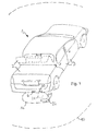
- An in Fig. 1 in the whole with 1 designated motor vehicle has designed as a tailgate first vehicle part 2, which is adjustable between an open and a closed position and allows access to a loading space not shown in detail in the drawing.
- the motor vehicle 2 has a plurality of doors designed as second vehicle parts 3, via which the interior of the motor vehicle 1 is accessible.
- the motor vehicle 2 For locking and unlocking the first and second vehicle parts 2, 3 located in the closed position, the motor vehicle 2 has an in Fig. 2 This has for each locking or unlocking vehicle part 2, 3 each have a servomotor, by means of which in a conventional manner each arranged on the respective vehicle part 2, 3 latch between a locking position and an open position is adjustable by motor. With the help of the locking / unlocking device 4, the vehicle parts 2, 3 can be centrally locked or unlocked.
- the motor vehicle 1 has at least one access authorization means 5, which can be carried by the user of the motor vehicle 1, for example in his pocket.
- the access authorization means 5 can be, for example, a vehicle key or a key card which cooperates wirelessly with a detection device 6 arranged in the motor vehicle.
- the second vehicle parts have door handles on which microswitches not shown in detail in the drawing are arranged, which transmit a switch-on signal to a switching device 7 upon actuation of the door handles, which causes the switching on of the detection device 6.
- the detection device 6 has a first transmitter 8 for emitting a first electromagnetic alternating field 9. If the access authorization means 5 are within an in Fig. 2 A first receiver 11 arranged in the access authorization means 5 receives the first alternating electromagnetic field 9 as soon as it is received, a second transmitter 12 integrated into the access authorization means 5 emits a second alternating electromagnetic field 13 which is located preferably differs from the frequency of the first alternating electromagnetic field 9 with respect to its frequency. The second electromagnetic alternating field 13 is received by a second receiver 14 arranged in the detection device 6, whereupon it generates a control signal which indicates the presence of the access authorization means 5 in the first surrounding area 10. If the access authorization means 5 is located outside the first surrounding area 10, the first receiver 11 does not receive the first alternating electromagnetic field 9 or with insufficient signal strength. In this case, the second transmitter 12 does not emit the second electromagnetic alternating field 13.
- the detection device 6 is connected via a control device 15 with the unlocking / locking device 4. If the detection device 6 determines that the access authorization means 5 is present in the first surrounding area 10, it transmits the control signal to the control device 15. This then generates a release signal for unlocking the locking / unlocking device 4. In response to the release signal, the servomotors the unlocking / locking device 4 is positioned.
- the first surrounding area 10 is chosen to be so large that it delimits the first vehicle part 2 and all second vehicle parts 3.
- the locking / unlocking device 4 is locked and the detection device 6 is switched off via the switching device 7.
- the detection device 6 can also be checked whether the access authorization means 5 in a in Fig. 1 dashed lines shown second environmental region 16 of the detection device 6 is arranged.
- the second surrounding area 16 is smaller than the first surrounding area 10 and is completely contained therein.
- Fig. 1 it can be seen that the second surrounding area 16 is arranged close to the first vehicle part 2.
- the check whether the access authorization means 5 is present in the second surrounding area 16 takes place in a similar manner as the check whether the access authorization means 5 is present in the first surrounding area 10, but in the first-mentioned check the transmission power of the first station 8 and / or or the second transmitter 12 is smaller than in the last-mentioned review.
- the detection device 6 may have an adjusting device 17 connected to the first transmitter 8 for changing the transmission power of the first transmitter 8.
- the first vehicle part 2 can be automatically pivoted by means of an actuating device 18 between the open position and the closed position. So that the vehicle user can communicate his desire to open and / or close the first vehicle part 2 without contact to the actuating device 18, the motor vehicle 1 has a proximity sensor 19, which has a sensor arrangement 20 with a plurality of capacitive sensor elements 24 in the region of the rear bumper.
- the sensor elements 24 may be designed, for example, strip-shaped and arranged parallel to one another. They are preferably applied to the inside of the bumper.
- this sensor arrangement 20 is a in Fig. 1 dotted rimmed part of the outer region 21 of the motor vehicle 1 on the presence of a body part 22, such as a foot or leg monitored by the vehicle user.
- a body part 22 such as a foot or leg monitored by the vehicle user.
- the detection device 6 is turned on or from a rest position with reduced power consumption switched to an operating position.
- the proximity sensor 19 is connected for this purpose via the control device 15 to the switching device 7.
- the control device 15 generates an actuating control signal triggering the adjustment of the first vehicle part 2 when the proximity sensor 19 detects the presence of the body part 22 in the monitored part of the outside area 21 and the detection device 6 detects the presence of the access authorization means 5 in the second surrounding area 16.
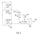
- the proximity sensor 19 for each sensor element 24 each has a switching device which comprises a plurality of controllable electronic switching elements 23a, 23b, 23c.
- Each switching element 23a, 23b, 23c each has a control input which is connected to a clock signal output of a clock generator.
- a first clock signal T1 is applied to a control input of a first switching element 23a, a second clock signal T2 to a control input of a second switching element 23b, and a third clock signal T3 to a control input of a third switching element 23c.
- a first terminal of a first resistor 25 can be connected via the first switching element 23a to a first operating voltage terminal and via the second switching element 23b to a second operating voltage terminal.
- a second terminal of the first resistor 25 is connected via one of the sensor elements 24 and via a series circuit consisting of a second resistor 26 and a capacitor 27 to the first operating voltage terminal.
- the individual sensor elements 24 are repeatedly connected via the first resistor 25 with an applied voltage at the second operating voltage V CC by the first switching element 23 a and the third switching element open and the second switching element 23 b are closed. As a result, the relevant sensor element 24 is charged.
- the second switching element 23b is opened and the third switching element 23c is closed.
- the charge stored in the sensor element 24 is transferred wholly or partially to the capacitor 27.
- V Ref is the voltage across the capacitor C Ref
- Vcc is the potential at the second operating voltage terminal
- C S is the capacitance of the sensor element dependent on the presence of the parasitic capacitance body part
- C Ref is the capacitance of the capacitor
- n is the number of the cycle.
- the voltage V Ref is applied via a measuring amplifier 28 to a measuring signal output 29 which is connected to the control device for evaluating the measuring signal. This may for example comprise a comparator for comparing the measurement signal with a reference value. If the measured signal is greater in magnitude than the reference value, the body part 22 is detected.
- the switching elements 23a, 23b, 23c and / or the clock can be integrated into a semiconductor component 30 as an integrated circuit.
- Fig. 5 shows a further embodiment in which the third switching element 23 c between the second terminal of the first resistor 25 and the series circuit consisting of the second resistor 26 and the capacitor 27 is arranged. In each case a connection of the sensor element 24 and the capacitor 27 are fixedly connected to the first operating voltage connection. Otherwise, the in Fig. 5 shown circuit of in Fig. 3 ,
- a position sensor 31 is provided, which is preferably designed as a switch.
- the control device 15 is in control connection with the position transmitter 31 and the actuating device 18 such that the first vehicle part 2 is opened when it is in the closed position when the actuating control signal occurs. If the first vehicle part 2 is not in the closed position when the actuation control signal occurs, the first vehicle part 2 is closed.
Landscapes
- Engineering & Computer Science (AREA)
- Mechanical Engineering (AREA)
- Computer Networks & Wireless Communication (AREA)
- Physics & Mathematics (AREA)
- General Physics & Mathematics (AREA)
- Human Computer Interaction (AREA)
- Lock And Its Accessories (AREA)
- Power-Operated Mechanisms For Wings (AREA)
Abstract
Description
- Die Erfindung betrifft ein Kraftfahrzeug mit mindestens einem in eine Offen- und eine Schließstellung verstellbaren Fahrzeugteil, insbesondere einer Heckklappe und/oder einer Fahrzeugtüre, mit einer Betätigungseinrichtung zum automatischen Verstellen des Fahrzeugteils zwischen der Offen- und der Schließstellung, mit einem Näherungssensor, der einen Teil eines Außenbereichs des Kraftfahrzeugs auf die Anwesenheit eines Körperteils eines Benutzers überwacht, mit einem Zugangsberechtigungsmittel und einer Detektionseinrichtung, mittels der das Vorhandensein des Zugangsberechtigungsmittels berührungslos in einem Umgebungsbereich der Detektionseinrichtung detektierbar ist, mit einer mit dem Näherungssensor, der Detektionseinrichtung und der Betätigungseinrichtung verbundenen Steuereinrichtung, die derart ausgestaltet ist, dass ein das Verstellen des Fahrzeugsteils auslösendes Betätigungssteuersignal erzeugt wird, wenn der Näherungssensor die Anwesenheit des Körperteils in dem Teil des Außenbereichs und die Detektionseinrichtung das Vorhandensein des Zugangsberechtigungsmittels in dem Umgebungsbereich detektieren, und wobei die Steuereinrichtung mit einer Schalteinrichtung zum Ein- und Ausschalten der Detektionseinrichtung verbunden ist. Unter einem Fahrzeugteil wird insbesondere eine Schwenktüre, eine Flügeltüre, eine Schiebetüre, eine Frontklappe, eine Heckklappe und/oder ein Deckel verstanden.
- Ein derartiges Kraftfahrzeug, das mehrere Türen und eine Heckklappe hat, ist aus
DE 10 2004 0471 709 B3 - Es besteht deshalb die Aufgabe ein Kraftfahrzeug der eingangs genannten Art zu schaffen, bei dem die für das berührungslose Auslösen der Betätigungseinrichtung benötigten elektrischen Komponenten einen geringen Stromverbrauch ermöglichen.
- Diese Aufgabe wird dadurch gelöst, dass der Näherungssensor zum Detektieren des Körperteils mindestens ein kapazitives Sensorelement aufweist, und dass die Steuereinrichtung derart mit der Schalteinrichtung in Steuerverbindung steht, dass die Detektionseinrichtung eingeschaltet wird, wenn der Näherungssensor die Anwesenheit des Körperteils in dem Teil des Außenbereichs detektiert. Dabei wird unter "einschalten" auch ein teilweises Einschalten der Detektionseinrichtung verstanden, beispielsweise wenn die Detektionseinrichtung zwischen einer Betriebsstellung und einer Ruhestellung, in der die Stromaufnahme gegenüber der Betriebsstellung reduziert ist, umschaltbar ist.
- In vorteilhafter Weise ermöglicht der kapazitive Näherungssensor im Vergleich zu einem entsprechenden optischen Näherungssensor oder einem Näherungssensor, der mit Ultraschall oder Radarstrahlung arbeitet, einen sehr geringen Stromverbrauch. Zwar ist der Stromverbrauch der Detektionseinrichtung noch relativ groß, jedoch wirkt sich dies in der Praxis kaum aus, weil die Steuereinrichtung die Detektionseinrichtung erst einschaltet, nachdem der Näherungssensor die Anwesenheit des Körperteils detektiert hat. Die Detektionseinrichtung braucht deshalb jeweils nur für eine kurze Zeitdauer eingeschaltet zu sein.
- Vorteilhaft ist, wenn die Steuereinrichtung derart mit der Schalteinrichtung in Steuerverbindung steht, dass die Detektionseinrichtung ausgeschaltet wird, wenn der Näherungssensor die Anwesenheit des Körperteils in dem Teil des Außenbereichs nicht detektiert. Die Detektionseinrichtung ist also jeweils nur so lange in Betrieb, wie der Näherungssensor die Anwesenheit des Körperteils anzeigt. Somit ermöglichen die für das berührungslose Auslösen der Betätigungseinrichtung benötigten Einrichtungen einen noch geringere Stromaufnahme.
- Bei einer anderen vorteilhaften Ausgestaltung der Erfindung steht die Steuereinrichtung derart mit der Schalteinrichtung in Steuerverbindung, dass die Detektionseinrichtung ausgeschaltet wird, wenn diese das Vorhandensein des Zugangsberechtigungsmittels in dem Umgebungsbereich nicht detektiert. Die Detektionseinrichtung wird also ausgeschaltet, sobald das Zugangsberechtigungsmittel aus dem zu überwachenden Umgebungsbereich entfernt wird.
- Bei zweckmäßigen Ausführungsform der Erfindung steht die Steuereinrichtung derart mit der Schalteinrichtung und einem Zeitgeber in Steuerverbindung, dass die Detektionseinrichtung nach Ablauf einer vorbestimmten maximale Einschaltzeitdauer abgeschaltet wird. Auch durch diese Maßnahme kann eine geringe Stromaufnahme erreicht werden.
- Bei einer Weiterbildung der Erfindung weist der Näherungssensor mindestens eine mit einem Taktgeber in Steuerverbindung stehende Schaltvorrichtung auf, mittels der das Sensorelement wiederholt zum Aufladen auf eine vorbestimmte elektrische Spannung mit einer elektrischen Spannungsquelle und jeweils danach zum Entladen des Sensorelements mit einem Strom-Spannungskonverter verbindbar ist, wobei der Strom-Spannungskonverter einen Messsignalausgang zum Ausgeben eines von der im Sensorelement gespeicherten Ladung abhängigen Messsignals aufweist, und wobei der Messsignalausgang zum Auswerten des Messsignals mit der Steuereinrichtung verbunden ist. In vorteilhafter Weise ermöglicht diese Ausgestaltung des Näherungssensor nicht nur einen geringen Stromverbrauch sondern auch eine weitgehend störungsfreie berührungslose Detektion des Körperteils des Benutzers. Die Steuereinrichtung kann z.B. eine Vergleichseinrichtung zum Vergleichen der Messspannung mit einem Referenz- oder Schwellenwert und/oder Mittel zum Bestimmen der Anstiegsgeschwindigkeit der Messspannung aufweisen.
- Vorteilhaft ist, wenn der Strom-Spannungskonverter eine Reihenschaltung, bestehend aus einem Kondensator und einem ohmschen Widerstand aufweist, die mit Hilfe der Schaltvorrichtung zu dem Sensorelement parallel geschaltet werden kann. Der Stromkonverter ermöglich dann einen einfachen und kostengünstigen Aufbau.
- Bei einer bevorzugten Ausgestaltung der Erfindung weist der Näherungssensor Mittel zum Erkennen mindestens eines vorbestimmten Bewegungsablaufs oder Bewegungsprofils des Körperteils auf, wobei die Detektionseinrichtung eine Stelleinrichtung zum Verändern der Größe des Umgebungsbereichs hat, und wobei die Mittel zum Erkennen des Bewegungsablaufs derart mit der Stelleinrichtung in Steuerverbindung stehen, dass beim Detektieren des vorbestimmten Bewegungsablaufs oder Bewegungsprofils die Größe des Umgebungsbereichs verändert wird. Der Benutzer des Kraftfahrzeugs kann also die Größe des Umgebungsbereichs berührungslos individuell einstellen, indem er ein bestimmtes Bewegungsprofil an den Näherungssensor anlegt. Der jeweils eingestellte Wert wird bevorzugt in einem nichtflüchtigen Speicher abgelegt, damit er auch dann gespeichert bleibt, wenn die Fahrzeugbatterie einmal abgeklemmt oder die Stromversorgung zu der Steuereinrichtung unterbrochen sein sollte.
- Vorteilhaft ist, wenn der Näherungssensor mehrere voneinander beabstandete Sensorelemente aufweist, mit denen jeweils das Körperteil des Benutzers berührungslos detektierbar ist. Die Steuereinrichtung kann dann derart ausgestaltet sein, dass sie die Richtung, in der das Körperteil in dem zu überwachenden Teil des Außenbereichs des Kraftfahrzeugs relativ zu diesem bewegt wird, anhand des zeitlichen Verläufe der Messsignale der einzelnen Sensorelemente ermitteln kann und das Öffnen und/oder Schließen des Fahrzeugteils nur dann einleitet, wenn die ermittelte Richtung mit einer vorbestimmten Richtung übereinstimmt. Dadurch kann ein versehentliches Öffnen und/oder Schließen des Fahrzeugteils weitestgehend vermieden werden.
- Nachfolgend sind Ausführungsbeispiele der Erfindung anhand der Zeichnung näher erläutert. Es zeigt:
- Fig. 1
- eine schematische Darstellung eines Kraftfahrzeugs,
- Fig. 2
- ein Blockschaltbild,
- Fig. 3
- ein Schaltbild eines Kanals eines ersten Ausführungsbeispiels eines mehrka- naligen kapazitiven Näherungssensors,
- Fig. 4
- eine graphische Darstellung der elektrischen Spannung an einem Kondensa- tor des in
Fig. 3 gezeigten Ausführungsbeispiels, wobei auf der Abszisse die Zeit in Taktzyklen und auf der Ordinate die elektrische Spannung aufgetragen sind, und - Fig.5
- ein Schaltbild eines Kanals eines zweiten Ausführungsbeispiels eines kapazitiven Näherungssensors.
- Ein in
Fig. 1 im Ganzen mit 1 bezeichnetes Kraftfahrzeug hat ein als Heckklappe ausgestaltetes erstes Fahrzeugteil 2, das zwischen einer Offen- und eine Schließstellung verstellbar ist und einen Zugang zu einem in der Zeichnung nicht näher dargestellten Laderaum ermöglicht. Außerdem weist das Kraftfahrzeug 2 mehrere als Türen ausgestaltete zweite Fahrzeugteile 3 auf, über die der Innenraum des Kraftfahrzeugs 1 zugänglich ist. - Zum Ver- und Entriegeln der in Schließstellung befindlichen ersten und zweiten Fahrzeugteile 2, 3 hat das Kraftfahrzeug 2 eine in
Fig. 2 nur schematisch dargestellte Ent-/Verriegelungseinrichtung 4. Diese weist für jedes zu verriegelnde bzw. entriegelnde Fahrzeugteil 2, 3 jeweils einen Stellmotor auf, mit dessen Hilfe in an sich bekannter Weise ein jeweils an dem betreffenden Fahrzeugteil 2, 3 angeordneter Riegel zwischen einer Verriegelungsstellung und einer Offenstellung motorisch verstellbar ist. Mit Hilfe der Ent-/Verriegelungseinrichtung 4 können die Fahrzeugteile 2, 3 zentral ver- bzw. entriegelt werden. - Das Kraftfahrzeug 1 hat mindestens ein Zugangsberechtigungsmittel 5, das vom Benutzer des Kraftfahrzeugs 1 beispielsweise in der Tasche mitgeführt werden kann. Das Zugangsberechtigungsmittel 5 kann zum Beispiel ein Fahrzeugschlüssel oder eine Keycard sein, der bzw. die drahtlos mit einer im Kraftfahrzeug angeordneten Detektionseinrichtung 6 zusammenwirkt. Die zweiten Fahrzeugteile weisen Türgriffe auf, an denen in der Zeichnung nicht näher dargestellte Mikroschalter angeordnet sind, die beim Betätigen der Türgriffe ein Einschaltsignal an eine Schalteinrichtung 7 übermitteln, welches das Einschalten der Detektionseinrichtung 6 veranlasst.
- Die Detektionseinrichtung 6 hat einen ersten Sender 8 zur Aussendung eines ersten elektromagnetischen Wechselfelds 9. Wenn sich das Zugangsberechtigungsmittel 5 innerhalb eines in
Fig. 2 strichliniert dargestellten ersten Umgebungsbereichs 10 der Detektionseinrichtung 6 befindet, empfängt ein in dem Zugangsberechtigungsmittel 5 angeordneter erster Empfänger 11 das erste elektromagnetische Wechselfeld 9. Sobald dieses empfangen wird, sendet ein in das Zugangsberechtigungsmittel 5 integrierter zweiter Sender 12 ein zweites elektromagnetisches Wechselfeld 13 aus, das sich bezüglich seiner Frequenz vorzugsweise von der Frequenz des ersten elektromagnetischen Wechselfelds 9 unterscheidet. Das zweite elektromagnetische Wechselfeld 13 wird von einem in der Detektionseinrichtung 6 angeordneten zweiten Empfänger 14 empfangen, woraufhin diese ein Steuersignal erzeugt, welches die Anwesenheit des Zugangsberechtigungsmittels 5 in dem ersten Umgebungsbereich 10 anzeigt. Befindet sich das Zugangsberechtigungsmittel 5 außerhalb des ersten Umgebungsbereichs 10, empfängt der erste Empfänger 11 das erste elektromagnetische Wechselfeld 9 nicht oder mit zu geringer Signalstärke. In diesem Fall sendet der zweite Sender 12 das zweite elektromagnetische Wechselfeld 13 nicht aus. - Wie in
Fig. 2 erkennbar ist, ist die Detektionseinrichtung 6 über eine Steuereinrichtung 15 mit der Ent-/Verriegelungseinrichtung 4 verbunden. Wenn die Detektionseinrichtung 6 feststellt, dass das Zugangsberechtigungsmittel 5 in dem ersten Umgebungsbereich 10 vorhanden ist, übermittelt sie das Steuersignal an die Steuereinrichtung 15. Diese erzeugt dann ein Freigabesignal für das Entriegeln der Ent-/Verriegelungseinrichtung 4. In Abhängigkeit von dem Freigabesignal werden die Stellmotoren der Ent-/Verriegelungseinrichtung 4 positioniert. InFig. 1 ist erkennbar, dass der erste Umgebungsbereich 10 so groß gewählt ist, dass es das erste Fahrzeugteil 2 und alle zweiten Fahrzeugteile 3 umgrenzt. - Sobald das Zugangsberechtigungsmittel 5 aus dem ersten Umgebungsbereich 10 entfernt wird, wird die Ent-/Verriegelungseinrichtung 4 verriegelt und die Detektionseinrichtung 6 wird über die Schalteinrichtung 7 abgeschaltet.
- Mit Hilfe der Detektionseinrichtung 6 kann außerdem überprüft werden, ob das Zugangsberechtigungsmittel 5 in einem in
Fig. 1 strichliniert dargestellten zweiten Umgebungsbereich 16 der Detektionseinrichtung 6 angeordnet ist. Der zweite Umgebungsbereich 16 ist kleiner als der erste Umgebungsbereich 10 und ist vollständig in diesem enthalten. InFig. 1 ist erkennbar, dass der zweite Umgebungsbereich 16 dicht an dem ersten Fahrzeugteil 2 angeordnet ist. Die Überprüfung, ob das Zugangsberechtigungsmittel 5 in dem zweiten Umgebungsbereich 16 anwesend ist, erfolgt in entsprechender Weise wie die Überprüfung, ob das Zugangsberechtigungsmittel 5 in dem ersten Umgebungsbereich 10 anwesend ist, wobei jedoch bei der zuerst genannten Überprüfung die Sendeleistung des ersten Senders 8 und/oder des zweiten Senders 12 kleiner gewählt wird als bei der zuletzt genannten Überprüfung. Zu diesem Zweck kann die Detektionseinrichtung 6 eine mit dem ersten Senders 8 verbundene Stelleinrichtung 17 zum Verändern der Sendeleistung des ersten Senders 8 aufweisen. - Das erste Fahrzeugteil 2 kann mit Hilfe einer Betätigungseinrichtung 18 automatisch zwischen der Offenstellung und der Schließstellung verschwenkt werden. Damit der Fahrzeugbenutzer seinen Wunsch, das erste Fahrzeugteil 2 zu öffnen und/oder zu schließen, berührungslos an die Betätigungseinrichtung 18 übermitteln kann, hat das Kraftfahrzeug 1 einen Näherungssensor 19, der im Bereich des hinteren Stoßfängers eine Sensoranordnung 20 mit mehreren kapazitiven Sensorelementen 24 aufweist. Die Sensorelemente 24 können beispielsweise streifenförmig ausgestaltet und parallel zueinander angeordnet sein. Sie sind bevorzugt auf die Innenseite des Stoßfängers aufgebracht.
- Mit Hilfe dieser Sensoranordnung 20 wird ein in
Fig. 1 punktiert umrandeter Teil des Außenbereichs 21 des Kraftfahrzeugs 1 auf die Anwesenheit eines Körperteils 22, wie z.B. eines Fußes oder Beins, des Fahrzeugbenutzers überwacht. Durch Einbringen des Körperteils 22 in den überwachten Teil des Außenbereichs 21 kann der Näherungssensor 19 betätigt werden. Durch das Auslösen des Näherungssensors 19 wird die Detektionseinrichtung 6 eingeschaltet bzw. aus einer Ruhestellung mit reduzierter Stromaufnahme in eine Betriebsstellung umgeschaltet. Der Näherungssensor 19 ist zu diesem Zweck über die Steuereinrichtung 15 mit der Schalteinrichtung 7 verbunden. - Die Steuereinrichtung 15 erzeugt ein das Verstellen des ersten Fahrzeugsteils 2 auslösendes Betätigungssteuersignal, wenn der Näherungssensor 19 die Anwesenheit des Körperteils 22 in dem überwachten Teil des Außenbereichs 21 und die Detektionseinrichtung 6 das Vorhandensein des Zugangsberechtigungsmittels 5 in dem zweiten Umgebungsbereich 16 detektieren.
- In
Fig. 3 ist erkennbar, dass der Näherungssensor 19 für jedes Sensorelement 24 jeweils eine Schaltvorrichtung aufweist, die mehrere steuerbare elektronische Schaltelemente 23a, 23b, 23c umfasst. Jedes Schaltelement 23a, 23b, 23c hat jeweils einen Steuereingang, der mit einem Taktsignalausgang eines Taktgebers verbunden ist. An einem Steuereingang eines ersten Schaltelements 23a liegt ein erstes Taktsignal T1, an einem Steuereingang eines zweiten Schaltelements 23b ein zweites Taktsignal T2 und an einem Steuereingang eines dritten Schaltelements 23c ein drittes Taktsignal T3 an. - Ein erster Anschluss eines ersten Widerstands 25 ist über das erste Schaltelement 23a mit einen ersten Betriebsspannungsanschluss und über das zweite Schaltelement 23b mit einem zweiten Betriebsspannungsanschluss verbindbar. Ein zweiter Anschluss des ersten Widerstands 25 ist über eines der Sensorelemente 24 und über eine Reihenschaltung, bestehend aus einem zweiten Widerstand 26 und einem Kondensator 27 mit dem ersten Betriebsspannungsanschluss verbunden.
- Mit Hilfe der Schaltvorrichtungen werden die einzelnen Sensorelemente 24 wiederholt über den ersten Widerstand 25 mit einer an dem zweiten Betriebsspannungsanschluss anliegenden elektrischen Spannung VCC verbunden, indem das erste Schaltelement 23a und das dritte Schaltelement geöffnet und das zweite Schaltelement 23b geschlossen werden. Dadurch wird das betreffende Sensorelement 24 aufgeladen.
- Danach wird das zweite Schaltelement 23b geöffnet und das dritte Schaltelement 23c geschlossen. Dadurch wird die in dem Sensorelemente 24 gespeicherte Ladung ganz oder teilweise zu dem Kondensator 27 übertragen.
- Danach werden in entsprechender Weise weitere Lade- und Entladezyklen durchgeführt. In
Fig. 4 ist der Verlauf der elektrischen Spannung an einem der Sensorelemente 24 schematisch dargestellt. Deutlich ist erkennbar, dass die Spannung, die nach dem Ladungstransfer an dem Sensorelement 24 anliegt, von Zyklus zu Zyklus zunimmt. Diese Spannung entspricht etwa der an dem Kondensator 27 anliegenden Spannung und kann wie folgt berechnet werden:
wobei VRef die Spannung am Kondensator CRef, Vcc das Potential am zweiten Betriebsspannungsanschluss, CS die von der Anwesenheit des als parasitäre Kapazität wirkenden Körperteils 22 abhängige Kapazität des Sensorelements, CRef die Kapazität des Kondensators und n die Nummer des Zyklus bedeuten. Die Spannung VRef wird über einen Messverstärker 28 an einen Messsignalausgang 29 angelegt, der zum Auswerten des Messsignals mit der Steuereinrichtung verbunden ist. Diese kann beispielsweise einen Komparator zum Vergleichen des Messsignals mit einem Referenzwert aufweisen. Wenn das Messsignal betragsmäßig größer ist als der Referenzwert, wird das Körperteil 22 detektiert. Erwähnt werden soll noch, dass die Schaltelemente 23a, 23b, 23c und/oder der Taktgeber als integrierte Schaltung in ein Halbleiterbauelement 30 integriert sein können. -
Fig. 5 zeigt ein weiteres Ausführungsbeispiel, bei dem das dritte Schaltelement 23c zwischen dem zweiten Anschluss des ersten Widerstands 25 und der Reihenschaltung, bestehend aus dem zweiten Widerstand 26 und dem Kondensator 27 angeordnet ist. Jeweils ein Anschluss des Sensorelements 24 und des Kondensators 27 sind fest mit dem ersten Betriebsspannungsanschluss verbunden. Im Übrigen entspricht die inFig. 5 gezeigte Schaltung der inFig. 3 . - Erwähnt werden soll noch, dass zum Überwachen der Schließstellung des ersten Fahrzeugteils 2 ein Positionsgeber 31 vorgesehen ist, der bevorzugt als Schalter ausgestaltet ist. Die Steuereinrichtung 15 steht derart mit dem Positionsgeber 31 und der Betätigungseinrichtung 18 in Steuerverbindung, dass das erste Fahrzeugteil 2 geöffnet wird, wenn es sich beim Auftreten des Betätigungssteuersignals in Schließstellung befindet. Befindet sich das erste Fahrzeugteil 2 beim Auftreten des Betätigungssteuersignals nicht in Schließstellung, wird das erste Fahrzeugteil 2 geschlossen.
-
- 1
- Kraftfahrzeug
- 2
- erstes Fahrzeugteil
- 3
- zweites Fahrzeugteil
- 4
- Ent-/Verriegelungseinrichtung
- 5
- Zugangsberechtigungsmittel
- 6
- Detektionseinrichtung
- 7
- Schalteinrichtung
- 8
- erster Sender
- 9
- erstes elektromagnetisches Wechselfeld
- 10
- erster Umgebungsbereich
- 11
- erster Empfänger
- 12
- zweiter Sender
- 13
- zweites elektromagnetisches Wechselfeld
- 14
- zweiter Empfänger
- 15
- Steuereinrichtung
- 16
- zweiter Umgebungsbereich
- 17
- Stelleinrichtung
- 18
- Betätigungseinrichtung
- 19
- Näherungssensor
- 20
- Sensoranordnung
- 21
- Teil des Außenbereichs
- 22
- Körperteil
- 23a
- erstes Schaltelement
- 23b
- zweites Schaltelement
- 23c
- drittes Schaltelement
- 24
- kapazitives Sensorelement
- 25
- erster Widerstand
- 26
- zweiten Widerstand
- 27
- Kondensator
- 28
- Messverstärker
- 29
- Messsignalausgang
- 30
- Halbleiterbauelement
- 31
- Positionsgeber
Claims (8)
- Kraftfahrzeug (1) mit mindestens einem in eine Offen- und eine Schließstellung verstellbaren Fahrzeugteil (2, 3), insbesondere einer Heckklappe und/oder einer Fahrzeugtüre, mit einer Betätigungseinrichtung (18) zum automatischen Verstellen des Fahrzeugteils (2, 3) zwischen der Offen- und der Schließstellung, mit einem Näherungssensor (19), der einen Teil eines Außenbereichs (21) des Kraftfahrzeugs (1) auf die Anwesenheit eines Körperteils (22) eines Benutzers überwacht, mit einem Zugangsberechtigungsmittel (5) und einer Detektionseinrichtung (6), mittels der das Vorhandensein des Zugangsberechtigungsmittels (5) berührungslos in einem Umgebungsbereich (16) der Detektionseinrichtung (6) detektierbar ist, mit einer mit dem Näherungssensor (19), der Detektionseinrichtung (6) und der Betätigungseinrichtung (18) verbundenen Steuereinrichtung (15), die derart ausgestaltet ist, dass ein das Verstellen des Fahrzeugsteils (2, 3) auslösendes Betätigungssteuersignal erzeugt wird, wenn der Näherungssensor (19) die Anwesenheit des Körperteils (22) in dem Teil des Außenbereichs (21) und die Detektionseinrichtung (6) das Vorhandensein des Zugangsberechtigungsmittels (5) in dem Umgebungsbereich (16) detektieren, und wobei die Steuereinrichtung (15) mit einer Schalteinrichtung (7) zum Ein- und Ausschalten der Detektionseinrichtung (6) verbunden ist, dadurch gekennzeichnet, dass der Näherungssensor (19) zum Detektieren des Körperteils (22) mindestens ein kapazitives Sensorelement (24) aufweist, und dass die Steuereinrichtung (15) derart mit der Schalteinrichtung (7) in Steuerverbindung steht, dass die Detektionseinrichtung (6) eingeschaltet wird, wenn der Näherungssensor (19) die Anwesenheit des Körperteils (22) in dem Teil des Außenbereichs (21) detektiert.
- Kraftfahrzeug (1) nach Anspruch 1, dadurch gekennzeichnet, dass die Steuereinrichtung (15) derart mit der Schalteinrichtung (7) in Steuerverbindung steht, dass die Detektionseinrichtung (6) ausgeschaltet wird, wenn der Näherungssensor (19) die Anwesenheit des Körperteils (22) in dem Teil des Außenbereichs (21) nicht detektiert.
- Kraftfahrzeug (1) nach Anspruch 1 oder 2, dadurch gekennzeichnet, dass die Steuereinrichtung (15) derart mit der Schalteinrichtung (7) in Steuerverbindung steht, dass die Detektionseinrichtung (6) ausgeschaltet wird, wenn diese das Vorhandensein des Zugangsberechtigungsmittels (5) in dem Umgebungsbereich (16) nicht detektiert.
- Kraftfahrzeug (1) nach einem der Ansprüche 1 bis 3, dadurch gekennzeichnet, die Steuereinrichtung (15) derart mit der Schalteinrichtung (7) und einem Zeitgeber in Steuerverbindung steht, dass die Detektionseinrichtung (6) nach Ablauf einer vorbestimmten maximale Einschaltzeitdauer abgeschaltet wird.
- Kraftfahrzeug (1) nach einem der Ansprüche 1 bis 4, dadurch gekennzeichnet, dass der Näherungssensor (19) mindestens eine mit einem Taktgeber in Steuerverbindung stehende Schaltvorrichtung aufweist, mittels der das Sensorelement (24) wiederholt zum Aufladen auf eine vorbestimmte elektrische Spannung mit einer elektrischen Spannungsquelle und jeweils danach zum Entladen des Sensorelements mit einem Strom-Spannungskonverter verbindbar ist, dass der Strom-Spannungskonverter einen Messsignalausgang (29) zum Ausgeben eines von der im Sensorelement (24) gespeicherten Ladung abhängigen Messsignals aufweist, und dass der Messsignalausgang (29) zum Auswerten des Messsignals mit der Steuereinrichtung verbunden ist.
- Kraftfahrzeug (1) nach einem der Ansprüche 1 bis 5, dadurch gekennzeichnet, dass der Strom-Spannungskonverter eine Reihenschaltung, bestehend aus einem Kondensator (27) und einem ohmschen Widerstand (26) aufweist, die mit Hilfe der Schaltvorrichtung zu dem Sensorelement (24) parallel geschaltet werden kann.
- Kraftfahrzeug (1) nach einem der Ansprüche 1 bis 6, dadurch gekennzeichnet, dass der Näherungssensor (19) Mittel zum Erkennen mindestens eines vorbestimmten Bewegungsablaufs oder Bewegungsprofils des Körperteils (22) aufweist, dass die Detektionseinrichtung (6) eine Stelleinrichtung (17) zum Verändern der Größe des Umgebungsbereichs (16) hat, und dass die Mittel zum Erkennen des Bewegungsablaufs derart mit der Stelleinrichtung (17) in Steuerverbindung stehen, dass beim Detektieren des vorbestimmten Bewegungsablaufs oder Bewegungsprofils die Größe des Umgebungsbereichs (16) verändert wird.
- Kraftfahrzeug (1) nach einem der Ansprüche 1 bis 7, dadurch gekennzeichnet, dass der Näherungssensor (19) mehrere voneinander beabstandete Sensorelemente (24) aufweist, mit denen jeweils das Körperteil (22) des Benutzers berührungslos detektierbar ist.
Priority Applications (1)
| Application Number | Priority Date | Filing Date | Title |
|---|---|---|---|
| EP20080102249 EP2098671B1 (de) | 2008-03-04 | 2008-03-04 | Kraftfahrzeug mit einem automatisch in eine Offen- und eine Schließstellung verstellbaren Fahrzeugteil |
Applications Claiming Priority (1)
| Application Number | Priority Date | Filing Date | Title |
|---|---|---|---|
| EP20080102249 EP2098671B1 (de) | 2008-03-04 | 2008-03-04 | Kraftfahrzeug mit einem automatisch in eine Offen- und eine Schließstellung verstellbaren Fahrzeugteil |
Publications (2)
| Publication Number | Publication Date |
|---|---|
| EP2098671A1 true EP2098671A1 (de) | 2009-09-09 |
| EP2098671B1 EP2098671B1 (de) | 2013-07-31 |
Family
ID=39674861
Family Applications (1)
| Application Number | Title | Priority Date | Filing Date |
|---|---|---|---|
| EP20080102249 Active EP2098671B1 (de) | 2008-03-04 | 2008-03-04 | Kraftfahrzeug mit einem automatisch in eine Offen- und eine Schließstellung verstellbaren Fahrzeugteil |
Country Status (1)
| Country | Link |
|---|---|
| EP (1) | EP2098671B1 (de) |
Cited By (8)
| Publication number | Priority date | Publication date | Assignee | Title |
|---|---|---|---|---|
| DE102011051434A1 (de) * | 2011-06-29 | 2013-01-03 | Huf Hülsbeck & Fürst Gmbh & Co. Kg | Kapazitive Sensoranordnung und Verfahren zur Erfassung von Betätigungsgesten an einem Kraftfahrzeug |
| FR2979873A1 (fr) * | 2011-09-12 | 2013-03-15 | Valeo Securite Habitacle | Procede d'ouverture d'un ouvrant de vehicule automobile |
| DE102012014677A1 (de) * | 2012-07-25 | 2014-01-30 | Brose Fahrzeugteile Gmbh & Co. Kg, Hallstadt | Verfahren zur Ansteuerung einer Verschlusselementanordnung insbesondere eines Kraftfahrzeugs |
| WO2014060152A1 (de) | 2012-10-20 | 2014-04-24 | Volkswagen Aktiengesellschaft | VERFAHREN UND VORRICHTUNG ZUR BESTIMMUNG EINES ABSTANDS UND ZUR BETÄTIGUNG EINES SCHLIEßELEMENTS EINES FAHRZEUGS |
| CN104724055A (zh) * | 2013-11-07 | 2015-06-24 | 博泽汽车零件哈尔施塔特有限责任两合公司 | 用于操控机动车的闭锁元件组件的方法 |
| US9214083B2 (en) | 2012-07-19 | 2015-12-15 | Hyundai Mobis Co., Ltd. | Apparatus and method for controlling automatic opening of trunk |
| EP3141685B1 (de) | 2009-07-17 | 2020-07-08 | Huf Hülsbeck & Fürst GmbH & Co. KG | Moduleinheit mit sensoreinrichtung |
| EP2824002B1 (de) | 2010-11-04 | 2021-05-12 | Huf Hülsbeck & Fürst GmbH & Co. KG | Verfahren zum Öffnen oder Schließen eines Kraftfahrzeugs |
Citations (5)
| Publication number | Priority date | Publication date | Assignee | Title |
|---|---|---|---|---|
| DE19901364A1 (de) * | 1998-01-19 | 1999-07-22 | Marquardt Gmbh | Schließsystem, insbesondere für Kraftfahrzeug |
| EP0965710A2 (de) * | 1998-06-18 | 1999-12-22 | Toyota Jidosha Kabushiki Kaisha | Fahrzeugsteuerungssystem |
| EP0999102A2 (de) * | 1998-11-06 | 2000-05-10 | Robert Bosch Gmbh | Zugangsberechtigungssystem für ein Kraftfahrzeug |
| US20030095040A1 (en) * | 2001-11-19 | 2003-05-22 | Toshio Shimomura | Door control system and method for vehicles |
| DE102004041709B3 (de) | 2004-08-28 | 2005-10-27 | Bayerische Motoren Werke Ag | Fahrzeug mit automatisch öffnender Klappe |
-
2008
- 2008-03-04 EP EP20080102249 patent/EP2098671B1/de active Active
Patent Citations (5)
| Publication number | Priority date | Publication date | Assignee | Title |
|---|---|---|---|---|
| DE19901364A1 (de) * | 1998-01-19 | 1999-07-22 | Marquardt Gmbh | Schließsystem, insbesondere für Kraftfahrzeug |
| EP0965710A2 (de) * | 1998-06-18 | 1999-12-22 | Toyota Jidosha Kabushiki Kaisha | Fahrzeugsteuerungssystem |
| EP0999102A2 (de) * | 1998-11-06 | 2000-05-10 | Robert Bosch Gmbh | Zugangsberechtigungssystem für ein Kraftfahrzeug |
| US20030095040A1 (en) * | 2001-11-19 | 2003-05-22 | Toshio Shimomura | Door control system and method for vehicles |
| DE102004041709B3 (de) | 2004-08-28 | 2005-10-27 | Bayerische Motoren Werke Ag | Fahrzeug mit automatisch öffnender Klappe |
Cited By (19)
| Publication number | Priority date | Publication date | Assignee | Title |
|---|---|---|---|---|
| EP3141685B1 (de) | 2009-07-17 | 2020-07-08 | Huf Hülsbeck & Fürst GmbH & Co. KG | Moduleinheit mit sensoreinrichtung |
| EP2824002B2 (de) † | 2010-11-04 | 2025-02-19 | Huf Hülsbeck & Fürst GmbH & Co. KG | Verfahren zum Öffnen oder Schließen eines Kraftfahrzeugs |
| EP2824002B1 (de) | 2010-11-04 | 2021-05-12 | Huf Hülsbeck & Fürst GmbH & Co. KG | Verfahren zum Öffnen oder Schließen eines Kraftfahrzeugs |
| DE102011051434A1 (de) * | 2011-06-29 | 2013-01-03 | Huf Hülsbeck & Fürst Gmbh & Co. Kg | Kapazitive Sensoranordnung und Verfahren zur Erfassung von Betätigungsgesten an einem Kraftfahrzeug |
| US9605939B2 (en) | 2011-06-29 | 2017-03-28 | Huf Huelsbeck & Fuerst Gmbh & Co. Kg | Capacitive sensor array and method for detecting actuation gestures at a motor vehicle |
| CN103998299B (zh) * | 2011-09-12 | 2016-08-24 | 法雷奥安全座舱公司 | 用于开启机动车辆的可移动面板的方法 |
| CN103998299A (zh) * | 2011-09-12 | 2014-08-20 | 法雷奥安全座舱公司 | 用于开启机动车辆的可移动面板的方法 |
| JP2014530309A (ja) * | 2011-09-12 | 2014-11-17 | ヴァレオ セキュリテ アビタクル | 自動車の開閉パネルの開放方法 |
| FR2979873A1 (fr) * | 2011-09-12 | 2013-03-15 | Valeo Securite Habitacle | Procede d'ouverture d'un ouvrant de vehicule automobile |
| US9394737B2 (en) | 2011-09-12 | 2016-07-19 | U-Shin France Sas | Method for opening a movable panel of a motor vehicle |
| KR20140082961A (ko) * | 2011-09-12 | 2014-07-03 | 발레오 시큐리티 하비태클 | 자동차의 가동형 패널을 개방하기 위한 방법 |
| WO2013037806A1 (fr) * | 2011-09-12 | 2013-03-21 | Valeo Securite Habitacle | Procédé d'ouverture d'un ouvrant de véhicule automobile |
| US9214083B2 (en) | 2012-07-19 | 2015-12-15 | Hyundai Mobis Co., Ltd. | Apparatus and method for controlling automatic opening of trunk |
| DE102012014677A1 (de) * | 2012-07-25 | 2014-01-30 | Brose Fahrzeugteile Gmbh & Co. Kg, Hallstadt | Verfahren zur Ansteuerung einer Verschlusselementanordnung insbesondere eines Kraftfahrzeugs |
| DE102012020640A1 (de) | 2012-10-20 | 2014-04-24 | Volkswagen Aktiengesellschaft | Verfahren und Vorrichtung zur Bestimmung eines Abstands und zur Betätigung eines Schließelements eines Fahrzeugs |
| DE102012020640B4 (de) * | 2012-10-20 | 2020-12-24 | Volkswagen Aktiengesellschaft | Verfahren und Vorrichtung zur Bestimmung eines Abstands und zur Betätigung eines Schließelements eines Fahrzeugs |
| WO2014060152A1 (de) | 2012-10-20 | 2014-04-24 | Volkswagen Aktiengesellschaft | VERFAHREN UND VORRICHTUNG ZUR BESTIMMUNG EINES ABSTANDS UND ZUR BETÄTIGUNG EINES SCHLIEßELEMENTS EINES FAHRZEUGS |
| CN104724055B (zh) * | 2013-11-07 | 2017-05-17 | 博泽汽车零件哈尔施塔特有限责任两合公司 | 用于操控机动车的闭锁元件组件的方法 |
| CN104724055A (zh) * | 2013-11-07 | 2015-06-24 | 博泽汽车零件哈尔施塔特有限责任两合公司 | 用于操控机动车的闭锁元件组件的方法 |
Also Published As
| Publication number | Publication date |
|---|---|
| EP2098671B1 (de) | 2013-07-31 |
Similar Documents
| Publication | Publication Date | Title |
|---|---|---|
| EP2098671B1 (de) | Kraftfahrzeug mit einem automatisch in eine Offen- und eine Schließstellung verstellbaren Fahrzeugteil | |
| EP1505734B1 (de) | Kapazitiver Näherungsschalter | |
| EP2821296B1 (de) | Erfassungsverfahren für betätigungsgesten | |
| EP2568605B1 (de) | Kapazitive Sensoranordnung | |
| EP2098670B1 (de) | Kraftfahrzeug mit einem automatisch in eine Offen- und eine Schließstellung verstellbaren Fahrzeugteil | |
| DE102011008277A1 (de) | Sensoreinheit zum berührungslosen Betätigen einer Fahrzeugtür | |
| EP3075613A1 (de) | Virtueller schalter und verfahren zum betrieb eines solchen | |
| DE102012105266B4 (de) | Kapazitiver Annäherungssensor für ein Kraftfahrzeug | |
| WO2002096719A1 (de) | Anordnung zur drahtlosen informations- und/oder energieübertragung zwischen einem herausnehmbaren fahrzeugsitz und der fahrzeugkarosserie | |
| DE10012637A1 (de) | Sicherheitssystem zur Ermöglichung des authentifizierten Zugangs eines Individuums zu einem geschützten Bereich | |
| DE10131896B4 (de) | Kraftfahrzeug-Türschließsystem | |
| DE102015217575B3 (de) | Auswerteschaltung für einen kapazitiven Sensor, kapazitiver Sensor und Aktor in einem Kraftfahrzeug | |
| EP2550740B1 (de) | Elektronisches bauteil für eine sensorvorrichtung, sensorvorrichtung und verfahren zum konfigurieren einer sensorvorrichtung | |
| DE112021000779T5 (de) | Sensoranordnung zur kapazitiven Positionserkennung eines Objekts | |
| DE10206968A1 (de) | Verfahren zur Erkennung einer Bedienung einer Handhabe mit einem kapazitiven Sensor | |
| DE102012102422A1 (de) | Kapazitive Sensoranordnung zur Schaltung einer Türöffnung an einem Kraftfahrzeug und zugehöriges Verfahren | |
| DE102008051074B4 (de) | Verfahren und Vorrichtung zum Überwachen einer durch einen Leistungshalbleiterschalter angesteuerten Last | |
| EP2905901B1 (de) | Schaltungsanordnung und Verfahren zur Erfassung einer Kapazität und/oder einer Kapazitätsänderung eines kapazitiven Bauelements | |
| DE102015113663A1 (de) | Sensoranordnung für ein Kraftfahrzeug | |
| DE112015001308T5 (de) | Verfahren und System zum Treiben eines kapazitiven Sensors | |
| DE102012020640A1 (de) | Verfahren und Vorrichtung zur Bestimmung eines Abstands und zur Betätigung eines Schließelements eines Fahrzeugs | |
| EP2098672A1 (de) | Kraftfahrzeug mit einem automatisch in eine Offen- und eine Schließstellung verstellbaren Fahrzeugteil | |
| DE602004008765T2 (de) | Adaptiver Näherungssensor | |
| EP1363400A2 (de) | Sicherheitsschalter | |
| DE102015003320A1 (de) | Kapazitiver Näherungssensor für ein Fahrzeug |
Legal Events
| Date | Code | Title | Description |
|---|---|---|---|
| PUAI | Public reference made under article 153(3) epc to a published international application that has entered the european phase |
Free format text: ORIGINAL CODE: 0009012 |
|
| AK | Designated contracting states |
Kind code of ref document: A1 Designated state(s): AT BE BG CH CY CZ DE DK EE ES FI FR GB GR HR HU IE IS IT LI LT LU LV MC MT NL NO PL PT RO SE SI SK TR |
|
| AX | Request for extension of the european patent |
Extension state: AL BA MK RS |
|
| 17P | Request for examination filed |
Effective date: 20100223 |
|
| 17Q | First examination report despatched |
Effective date: 20100316 |
|
| AKX | Designation fees paid |
Designated state(s): AT BE BG CH CY CZ DE DK EE ES FI FR GB GR HR HU IE IS IT LI LT LU LV MC MT NL NO PL PT RO SE SI SK TR |
|
| GRAP | Despatch of communication of intention to grant a patent |
Free format text: ORIGINAL CODE: EPIDOSNIGR1 |
|
| GRAS | Grant fee paid |
Free format text: ORIGINAL CODE: EPIDOSNIGR3 |
|
| GRAA | (expected) grant |
Free format text: ORIGINAL CODE: 0009210 |
|
| AK | Designated contracting states |
Kind code of ref document: B1 Designated state(s): AT BE BG CH CY CZ DE DK EE ES FI FR GB GR HR HU IE IS IT LI LT LU LV MC MT NL NO PL PT RO SE SI SK TR |
|
| REG | Reference to a national code |
Ref country code: GB Ref legal event code: FG4D Free format text: NOT ENGLISH Ref country code: CH Ref legal event code: EP |
|
| REG | Reference to a national code |
Ref country code: AT Ref legal event code: REF Ref document number: 624777 Country of ref document: AT Kind code of ref document: T Effective date: 20130815 |
|
| REG | Reference to a national code |
Ref country code: IE Ref legal event code: FG4D Free format text: LANGUAGE OF EP DOCUMENT: GERMAN |
|
| REG | Reference to a national code |
Ref country code: DE Ref legal event code: R096 Ref document number: 502008010398 Country of ref document: DE Effective date: 20130926 |
|
| REG | Reference to a national code |
Ref country code: NL Ref legal event code: VDEP Effective date: 20130731 |
|
| REG | Reference to a national code |
Ref country code: LT Ref legal event code: MG4D |
|
| PG25 | Lapsed in a contracting state [announced via postgrant information from national office to epo] |
Ref country code: IS Free format text: LAPSE BECAUSE OF FAILURE TO SUBMIT A TRANSLATION OF THE DESCRIPTION OR TO PAY THE FEE WITHIN THE PRESCRIBED TIME-LIMIT Effective date: 20131130 Ref country code: PT Free format text: LAPSE BECAUSE OF FAILURE TO SUBMIT A TRANSLATION OF THE DESCRIPTION OR TO PAY THE FEE WITHIN THE PRESCRIBED TIME-LIMIT Effective date: 20131202 Ref country code: CY Free format text: LAPSE BECAUSE OF FAILURE TO SUBMIT A TRANSLATION OF THE DESCRIPTION OR TO PAY THE FEE WITHIN THE PRESCRIBED TIME-LIMIT Effective date: 20130807 Ref country code: HR Free format text: LAPSE BECAUSE OF FAILURE TO SUBMIT A TRANSLATION OF THE DESCRIPTION OR TO PAY THE FEE WITHIN THE PRESCRIBED TIME-LIMIT Effective date: 20130731 Ref country code: SE Free format text: LAPSE BECAUSE OF FAILURE TO SUBMIT A TRANSLATION OF THE DESCRIPTION OR TO PAY THE FEE WITHIN THE PRESCRIBED TIME-LIMIT Effective date: 20130731 Ref country code: LT Free format text: LAPSE BECAUSE OF FAILURE TO SUBMIT A TRANSLATION OF THE DESCRIPTION OR TO PAY THE FEE WITHIN THE PRESCRIBED TIME-LIMIT Effective date: 20130731 Ref country code: NO Free format text: LAPSE BECAUSE OF FAILURE TO SUBMIT A TRANSLATION OF THE DESCRIPTION OR TO PAY THE FEE WITHIN THE PRESCRIBED TIME-LIMIT Effective date: 20131031 |
|
| PG25 | Lapsed in a contracting state [announced via postgrant information from national office to epo] |
Ref country code: NL Free format text: LAPSE BECAUSE OF FAILURE TO SUBMIT A TRANSLATION OF THE DESCRIPTION OR TO PAY THE FEE WITHIN THE PRESCRIBED TIME-LIMIT Effective date: 20130731 Ref country code: LV Free format text: LAPSE BECAUSE OF FAILURE TO SUBMIT A TRANSLATION OF THE DESCRIPTION OR TO PAY THE FEE WITHIN THE PRESCRIBED TIME-LIMIT Effective date: 20130731 Ref country code: FI Free format text: LAPSE BECAUSE OF FAILURE TO SUBMIT A TRANSLATION OF THE DESCRIPTION OR TO PAY THE FEE WITHIN THE PRESCRIBED TIME-LIMIT Effective date: 20130731 Ref country code: PL Free format text: LAPSE BECAUSE OF FAILURE TO SUBMIT A TRANSLATION OF THE DESCRIPTION OR TO PAY THE FEE WITHIN THE PRESCRIBED TIME-LIMIT Effective date: 20130731 Ref country code: SI Free format text: LAPSE BECAUSE OF FAILURE TO SUBMIT A TRANSLATION OF THE DESCRIPTION OR TO PAY THE FEE WITHIN THE PRESCRIBED TIME-LIMIT Effective date: 20130731 Ref country code: GR Free format text: LAPSE BECAUSE OF FAILURE TO SUBMIT A TRANSLATION OF THE DESCRIPTION OR TO PAY THE FEE WITHIN THE PRESCRIBED TIME-LIMIT Effective date: 20131101 |
|
| PG25 | Lapsed in a contracting state [announced via postgrant information from national office to epo] |
Ref country code: CY Free format text: LAPSE BECAUSE OF FAILURE TO SUBMIT A TRANSLATION OF THE DESCRIPTION OR TO PAY THE FEE WITHIN THE PRESCRIBED TIME-LIMIT Effective date: 20130731 |
|
| PG25 | Lapsed in a contracting state [announced via postgrant information from national office to epo] |
Ref country code: CZ Free format text: LAPSE BECAUSE OF FAILURE TO SUBMIT A TRANSLATION OF THE DESCRIPTION OR TO PAY THE FEE WITHIN THE PRESCRIBED TIME-LIMIT Effective date: 20130731 Ref country code: RO Free format text: LAPSE BECAUSE OF FAILURE TO SUBMIT A TRANSLATION OF THE DESCRIPTION OR TO PAY THE FEE WITHIN THE PRESCRIBED TIME-LIMIT Effective date: 20130731 Ref country code: EE Free format text: LAPSE BECAUSE OF FAILURE TO SUBMIT A TRANSLATION OF THE DESCRIPTION OR TO PAY THE FEE WITHIN THE PRESCRIBED TIME-LIMIT Effective date: 20130731 Ref country code: SK Free format text: LAPSE BECAUSE OF FAILURE TO SUBMIT A TRANSLATION OF THE DESCRIPTION OR TO PAY THE FEE WITHIN THE PRESCRIBED TIME-LIMIT Effective date: 20130731 Ref country code: DK Free format text: LAPSE BECAUSE OF FAILURE TO SUBMIT A TRANSLATION OF THE DESCRIPTION OR TO PAY THE FEE WITHIN THE PRESCRIBED TIME-LIMIT Effective date: 20130731 |
|
| PG25 | Lapsed in a contracting state [announced via postgrant information from national office to epo] |
Ref country code: IT Free format text: LAPSE BECAUSE OF FAILURE TO SUBMIT A TRANSLATION OF THE DESCRIPTION OR TO PAY THE FEE WITHIN THE PRESCRIBED TIME-LIMIT Effective date: 20130731 Ref country code: ES Free format text: LAPSE BECAUSE OF FAILURE TO SUBMIT A TRANSLATION OF THE DESCRIPTION OR TO PAY THE FEE WITHIN THE PRESCRIBED TIME-LIMIT Effective date: 20130731 |
|
| PLBE | No opposition filed within time limit |
Free format text: ORIGINAL CODE: 0009261 |
|
| STAA | Information on the status of an ep patent application or granted ep patent |
Free format text: STATUS: NO OPPOSITION FILED WITHIN TIME LIMIT |
|
| 26N | No opposition filed |
Effective date: 20140502 |
|
| REG | Reference to a national code |
Ref country code: DE Ref legal event code: R097 Ref document number: 502008010398 Country of ref document: DE Effective date: 20140502 |
|
| PG25 | Lapsed in a contracting state [announced via postgrant information from national office to epo] |
Ref country code: LU Free format text: LAPSE BECAUSE OF FAILURE TO SUBMIT A TRANSLATION OF THE DESCRIPTION OR TO PAY THE FEE WITHIN THE PRESCRIBED TIME-LIMIT Effective date: 20140304 |
|
| REG | Reference to a national code |
Ref country code: CH Ref legal event code: PL |
|
| REG | Reference to a national code |
Ref country code: IE Ref legal event code: MM4A |
|
| PG25 | Lapsed in a contracting state [announced via postgrant information from national office to epo] |
Ref country code: CH Free format text: LAPSE BECAUSE OF NON-PAYMENT OF DUE FEES Effective date: 20140331 Ref country code: LI Free format text: LAPSE BECAUSE OF NON-PAYMENT OF DUE FEES Effective date: 20140331 Ref country code: IE Free format text: LAPSE BECAUSE OF NON-PAYMENT OF DUE FEES Effective date: 20140304 |
|
| REG | Reference to a national code |
Ref country code: AT Ref legal event code: MM01 Ref document number: 624777 Country of ref document: AT Kind code of ref document: T Effective date: 20140304 |
|
| PG25 | Lapsed in a contracting state [announced via postgrant information from national office to epo] |
Ref country code: AT Free format text: LAPSE BECAUSE OF NON-PAYMENT OF DUE FEES Effective date: 20140304 |
|
| REG | Reference to a national code |
Ref country code: FR Ref legal event code: PLFP Year of fee payment: 9 |
|
| PG25 | Lapsed in a contracting state [announced via postgrant information from national office to epo] |
Ref country code: MT Free format text: LAPSE BECAUSE OF FAILURE TO SUBMIT A TRANSLATION OF THE DESCRIPTION OR TO PAY THE FEE WITHIN THE PRESCRIBED TIME-LIMIT Effective date: 20130731 |
|
| PG25 | Lapsed in a contracting state [announced via postgrant information from national office to epo] |
Ref country code: BG Free format text: LAPSE BECAUSE OF FAILURE TO SUBMIT A TRANSLATION OF THE DESCRIPTION OR TO PAY THE FEE WITHIN THE PRESCRIBED TIME-LIMIT Effective date: 20130731 Ref country code: MC Free format text: LAPSE BECAUSE OF FAILURE TO SUBMIT A TRANSLATION OF THE DESCRIPTION OR TO PAY THE FEE WITHIN THE PRESCRIBED TIME-LIMIT Effective date: 20130731 |
|
| PGFP | Annual fee paid to national office [announced via postgrant information from national office to epo] |
Ref country code: GB Payment date: 20160302 Year of fee payment: 9 |
|
| PG25 | Lapsed in a contracting state [announced via postgrant information from national office to epo] |
Ref country code: HU Free format text: LAPSE BECAUSE OF FAILURE TO SUBMIT A TRANSLATION OF THE DESCRIPTION OR TO PAY THE FEE WITHIN THE PRESCRIBED TIME-LIMIT; INVALID AB INITIO Effective date: 20080304 Ref country code: BE Free format text: LAPSE BECAUSE OF FAILURE TO SUBMIT A TRANSLATION OF THE DESCRIPTION OR TO PAY THE FEE WITHIN THE PRESCRIBED TIME-LIMIT Effective date: 20140331 Ref country code: TR Free format text: LAPSE BECAUSE OF FAILURE TO SUBMIT A TRANSLATION OF THE DESCRIPTION OR TO PAY THE FEE WITHIN THE PRESCRIBED TIME-LIMIT Effective date: 20130731 |
|
| REG | Reference to a national code |
Ref country code: FR Ref legal event code: PLFP Year of fee payment: 10 |
|
| PGFP | Annual fee paid to national office [announced via postgrant information from national office to epo] |
Ref country code: FR Payment date: 20170213 Year of fee payment: 10 |
|
| GBPC | Gb: european patent ceased through non-payment of renewal fee |
Effective date: 20170304 |
|
| REG | Reference to a national code |
Ref country code: DE Ref legal event code: R081 Ref document number: 502008010398 Country of ref document: DE Owner name: HELLA GMBH & CO. KGAA, DE Free format text: FORMER OWNER: HELLA KGAA HUECK & CO., 59557 LIPPSTADT, DE |
|
| PG25 | Lapsed in a contracting state [announced via postgrant information from national office to epo] |
Ref country code: GB Free format text: LAPSE BECAUSE OF NON-PAYMENT OF DUE FEES Effective date: 20170304 |
|
| PG25 | Lapsed in a contracting state [announced via postgrant information from national office to epo] |
Ref country code: FR Free format text: LAPSE BECAUSE OF NON-PAYMENT OF DUE FEES Effective date: 20180331 |
|
| REG | Reference to a national code |
Ref country code: DE Ref legal event code: R084 Ref document number: 502008010398 Country of ref document: DE |
|
| PGFP | Annual fee paid to national office [announced via postgrant information from national office to epo] |
Ref country code: DE Payment date: 20260102 Year of fee payment: 19 |