EP2098582A1 - Organic inorganic composite material, process for producing the same, and functional electrode and functional device - Google Patents
Organic inorganic composite material, process for producing the same, and functional electrode and functional device Download PDFInfo
- Publication number
- EP2098582A1 EP2098582A1 EP06843619A EP06843619A EP2098582A1 EP 2098582 A1 EP2098582 A1 EP 2098582A1 EP 06843619 A EP06843619 A EP 06843619A EP 06843619 A EP06843619 A EP 06843619A EP 2098582 A1 EP2098582 A1 EP 2098582A1
- Authority
- EP
- European Patent Office
- Prior art keywords
- electrode
- organic
- inorganic composite
- composite material
- photoelectric conversion
- Prior art date
- Legal status (The legal status is an assumption and is not a legal conclusion. Google has not performed a legal analysis and makes no representation as to the accuracy of the status listed.)
- Granted
Links
- 229910003471 inorganic composite material Inorganic materials 0.000 title claims abstract description 54
- 238000006243 chemical reaction Methods 0.000 claims abstract description 66
- 229910044991 metal oxide Inorganic materials 0.000 claims abstract description 51
- 150000004706 metal oxides Chemical class 0.000 claims abstract description 51
- 239000011368 organic material Substances 0.000 claims abstract description 47
- 239000006087 Silane Coupling Agent Substances 0.000 claims abstract description 30
- OGIDPMRJRNCKJF-UHFFFAOYSA-N titanium oxide Inorganic materials [Ti]=O OGIDPMRJRNCKJF-UHFFFAOYSA-N 0.000 claims description 40
- GWEVSGVZZGPLCZ-UHFFFAOYSA-N Titan oxide Chemical compound O=[Ti]=O GWEVSGVZZGPLCZ-UHFFFAOYSA-N 0.000 claims description 37
- 150000001875 compounds Chemical class 0.000 claims description 26
- 239000010419 fine particle Substances 0.000 claims description 17
- 239000003792 electrolyte Substances 0.000 claims description 13
- 238000004519 manufacturing process Methods 0.000 claims description 12
- -1 trichlorosilane compound Chemical class 0.000 claims description 9
- 125000000524 functional group Chemical group 0.000 claims description 6
- 239000005052 trichlorosilane Substances 0.000 claims description 2
- 239000000758 substrate Substances 0.000 description 29
- 239000011521 glass Substances 0.000 description 21
- 239000000243 solution Substances 0.000 description 18
- 230000006870 function Effects 0.000 description 13
- 229910001887 tin oxide Inorganic materials 0.000 description 12
- 238000002360 preparation method Methods 0.000 description 11
- 239000000463 material Substances 0.000 description 10
- 239000011164 primary particle Substances 0.000 description 10
- XOLBLPGZBRYERU-UHFFFAOYSA-N tin dioxide Chemical compound O=[Sn]=O XOLBLPGZBRYERU-UHFFFAOYSA-N 0.000 description 10
- ZMANZCXQSJIPKH-UHFFFAOYSA-N Triethylamine Chemical compound CCN(CC)CC ZMANZCXQSJIPKH-UHFFFAOYSA-N 0.000 description 9
- 230000000052 comparative effect Effects 0.000 description 9
- 239000006185 dispersion Substances 0.000 description 9
- 238000004528 spin coating Methods 0.000 description 9
- DALJONTVJNRURD-UHFFFAOYSA-M 1-ethyl-4-pyridin-4-ylpyridin-1-ium;chloride Chemical compound [Cl-].C1=C[N+](CC)=CC=C1C1=CC=NC=C1 DALJONTVJNRURD-UHFFFAOYSA-M 0.000 description 6
- ZWEHNKRNPOVVGH-UHFFFAOYSA-N 2-Butanone Chemical compound CCC(C)=O ZWEHNKRNPOVVGH-UHFFFAOYSA-N 0.000 description 6
- WEVYAHXRMPXWCK-UHFFFAOYSA-N Acetonitrile Chemical compound CC#N WEVYAHXRMPXWCK-UHFFFAOYSA-N 0.000 description 6
- WYURNTSHIVDZCO-UHFFFAOYSA-N Tetrahydrofuran Chemical compound C1CCOC1 WYURNTSHIVDZCO-UHFFFAOYSA-N 0.000 description 6
- 239000008151 electrolyte solution Substances 0.000 description 6
- 150000002894 organic compounds Chemical class 0.000 description 6
- BASFCYQUMIYNBI-UHFFFAOYSA-N platinum Chemical compound [Pt] BASFCYQUMIYNBI-UHFFFAOYSA-N 0.000 description 6
- 238000011161 development Methods 0.000 description 5
- XEEYBQQBJWHFJM-UHFFFAOYSA-N Iron Chemical compound [Fe] XEEYBQQBJWHFJM-UHFFFAOYSA-N 0.000 description 4
- MCMNRKCIXSYSNV-UHFFFAOYSA-N Zirconium dioxide Chemical compound O=[Zr]=O MCMNRKCIXSYSNV-UHFFFAOYSA-N 0.000 description 4
- YRKCREAYFQTBPV-UHFFFAOYSA-N acetylacetone Chemical compound CC(=O)CC(C)=O YRKCREAYFQTBPV-UHFFFAOYSA-N 0.000 description 4
- 238000012360 testing method Methods 0.000 description 4
- XLYOFNOQVPJJNP-UHFFFAOYSA-N water Substances O XLYOFNOQVPJJNP-UHFFFAOYSA-N 0.000 description 4
- 239000011701 zinc Substances 0.000 description 4
- UUNGBOQAZQUJMZ-UHFFFAOYSA-N 3-bromopropyl(trichloro)silane Chemical compound Cl[Si](Cl)(Cl)CCCBr UUNGBOQAZQUJMZ-UHFFFAOYSA-N 0.000 description 3
- LFQSCWFLJHTTHZ-UHFFFAOYSA-N Ethanol Chemical compound CCO LFQSCWFLJHTTHZ-UHFFFAOYSA-N 0.000 description 3
- XUIMIQQOPSSXEZ-UHFFFAOYSA-N Silicon Chemical group [Si] XUIMIQQOPSSXEZ-UHFFFAOYSA-N 0.000 description 3
- HCHKCACWOHOZIP-UHFFFAOYSA-N Zinc Chemical compound [Zn] HCHKCACWOHOZIP-UHFFFAOYSA-N 0.000 description 3
- 229910052799 carbon Inorganic materials 0.000 description 3
- 229910052751 metal Inorganic materials 0.000 description 3
- 239000002184 metal Substances 0.000 description 3
- SOQBVABWOPYFQZ-UHFFFAOYSA-N oxygen(2-);titanium(4+) Chemical class [O-2].[O-2].[Ti+4] SOQBVABWOPYFQZ-UHFFFAOYSA-N 0.000 description 3
- IEQIEDJGQAUEQZ-UHFFFAOYSA-N phthalocyanine Chemical class N1C(N=C2C3=CC=CC=C3C(N=C3C4=CC=CC=C4C(=N4)N3)=N2)=C(C=CC=C2)C2=C1N=C1C2=CC=CC=C2C4=N1 IEQIEDJGQAUEQZ-UHFFFAOYSA-N 0.000 description 3
- 229910052697 platinum Inorganic materials 0.000 description 3
- 238000001179 sorption measurement Methods 0.000 description 3
- 125000006850 spacer group Chemical group 0.000 description 3
- YLQBMQCUIZJEEH-UHFFFAOYSA-N tetrahydrofuran Natural products C=1C=COC=1 YLQBMQCUIZJEEH-UHFFFAOYSA-N 0.000 description 3
- 229910052725 zinc Inorganic materials 0.000 description 3
- BDNKZNFMNDZQMI-UHFFFAOYSA-N 1,3-diisopropylcarbodiimide Chemical compound CC(C)N=C=NC(C)C BDNKZNFMNDZQMI-UHFFFAOYSA-N 0.000 description 2
- QPPGNUVNZBVHJE-UHFFFAOYSA-M 1-hexyl-4-pyridin-4-ylpyridin-1-ium;bromide Chemical compound [Br-].C1=C[N+](CCCCCC)=CC=C1C1=CC=NC=C1 QPPGNUVNZBVHJE-UHFFFAOYSA-M 0.000 description 2
- LLNQRNOPJAFMFQ-UHFFFAOYSA-N 11-bromoundecyl(trichloro)silane Chemical compound Cl[Si](Cl)(Cl)CCCCCCCCCCCBr LLNQRNOPJAFMFQ-UHFFFAOYSA-N 0.000 description 2
- WOFGXJUDMCOIBH-UHFFFAOYSA-N 11-bromoundecyl-chloro-dimethylsilane Chemical compound C[Si](C)(Cl)CCCCCCCCCCCBr WOFGXJUDMCOIBH-UHFFFAOYSA-N 0.000 description 2
- BLPSBRVIABXEHZ-UHFFFAOYSA-N 3-bromopropyl(trichloro)silane;toluene Chemical compound CC1=CC=CC=C1.Cl[Si](Cl)(Cl)CCCBr BLPSBRVIABXEHZ-UHFFFAOYSA-N 0.000 description 2
- ONCIZBPTIORBAV-UHFFFAOYSA-N 3-bromopropyl(triethoxy)silane;toluene Chemical compound CC1=CC=CC=C1.CCO[Si](OCC)(OCC)CCCBr ONCIZBPTIORBAV-UHFFFAOYSA-N 0.000 description 2
- LGJUXSUQQVUNOP-UHFFFAOYSA-N 4-(3-trichlorosilylpropyl)-n,n-bis[4-(3-trichlorosilylpropyl)phenyl]aniline Chemical compound C1=CC(CCC[Si](Cl)(Cl)Cl)=CC=C1N(C=1C=CC(CCC[Si](Cl)(Cl)Cl)=CC=1)C1=CC=C(CCC[Si](Cl)(Cl)Cl)C=C1 LGJUXSUQQVUNOP-UHFFFAOYSA-N 0.000 description 2
- 239000004925 Acrylic resin Substances 0.000 description 2
- 229920000178 Acrylic resin Polymers 0.000 description 2
- 229910002012 Aerosil® Inorganic materials 0.000 description 2
- RYGMFSIKBFXOCR-UHFFFAOYSA-N Copper Chemical compound [Cu] RYGMFSIKBFXOCR-UHFFFAOYSA-N 0.000 description 2
- 238000004566 IR spectroscopy Methods 0.000 description 2
- 239000002202 Polyethylene glycol Substances 0.000 description 2
- VYPSYNLAJGMNEJ-UHFFFAOYSA-N Silicium dioxide Chemical compound O=[Si]=O VYPSYNLAJGMNEJ-UHFFFAOYSA-N 0.000 description 2
- YXFVVABEGXRONW-UHFFFAOYSA-N Toluene Natural products CC1=CC=CC=C1 YXFVVABEGXRONW-UHFFFAOYSA-N 0.000 description 2
- 229920004890 Triton X-100 Polymers 0.000 description 2
- 238000004833 X-ray photoelectron spectroscopy Methods 0.000 description 2
- 239000004411 aluminium Substances 0.000 description 2
- 229910052782 aluminium Inorganic materials 0.000 description 2
- XAGFODPZIPBFFR-UHFFFAOYSA-N aluminium Chemical compound [Al] XAGFODPZIPBFFR-UHFFFAOYSA-N 0.000 description 2
- PNEYBMLMFCGWSK-UHFFFAOYSA-N aluminium oxide Inorganic materials [O-2].[O-2].[O-2].[Al+3].[Al+3] PNEYBMLMFCGWSK-UHFFFAOYSA-N 0.000 description 2
- JRPBQTZRNDNNOP-UHFFFAOYSA-N barium titanate Chemical compound [Ba+2].[Ba+2].[O-][Ti]([O-])([O-])[O-] JRPBQTZRNDNNOP-UHFFFAOYSA-N 0.000 description 2
- 229910002113 barium titanate Inorganic materials 0.000 description 2
- KOPOQZFJUQMUML-UHFFFAOYSA-N chlorosilane Chemical class Cl[SiH3] KOPOQZFJUQMUML-UHFFFAOYSA-N 0.000 description 2
- 229910052802 copper Inorganic materials 0.000 description 2
- 239000010949 copper Substances 0.000 description 2
- KCDCNGXPPGQERR-UHFFFAOYSA-N coumarin 343 Chemical compound C1CCC2=C(OC(C(C(=O)O)=C3)=O)C3=CC3=C2N1CCC3 KCDCNGXPPGQERR-UHFFFAOYSA-N 0.000 description 2
- VEVZSMAEJFVWIL-UHFFFAOYSA-O cyanidin cation Chemical compound [O+]=1C2=CC(O)=CC(O)=C2C=C(O)C=1C1=CC=C(O)C(O)=C1 VEVZSMAEJFVWIL-UHFFFAOYSA-O 0.000 description 2
- 238000003795 desorption Methods 0.000 description 2
- 238000009792 diffusion process Methods 0.000 description 2
- 239000000975 dye Substances 0.000 description 2
- 239000003822 epoxy resin Substances 0.000 description 2
- 239000011245 gel electrolyte Substances 0.000 description 2
- PCHJSUWPFVWCPO-UHFFFAOYSA-N gold Chemical compound [Au] PCHJSUWPFVWCPO-UHFFFAOYSA-N 0.000 description 2
- 229910052737 gold Inorganic materials 0.000 description 2
- 239000010931 gold Substances 0.000 description 2
- LNEPOXFFQSENCJ-UHFFFAOYSA-N haloperidol Chemical compound C1CC(O)(C=2C=CC(Cl)=CC=2)CCN1CCCC(=O)C1=CC=C(F)C=C1 LNEPOXFFQSENCJ-UHFFFAOYSA-N 0.000 description 2
- 229910003437 indium oxide Inorganic materials 0.000 description 2
- PJXISJQVUVHSOJ-UHFFFAOYSA-N indium(iii) oxide Chemical class [O-2].[O-2].[O-2].[In+3].[In+3] PJXISJQVUVHSOJ-UHFFFAOYSA-N 0.000 description 2
- 229910010272 inorganic material Inorganic materials 0.000 description 2
- 239000002608 ionic liquid Substances 0.000 description 2
- 229910052742 iron Inorganic materials 0.000 description 2
- UQSXHKLRYXJYBZ-UHFFFAOYSA-N iron oxide Inorganic materials [Fe]=O UQSXHKLRYXJYBZ-UHFFFAOYSA-N 0.000 description 2
- 235000013980 iron oxide Nutrition 0.000 description 2
- VBMVTYDPPZVILR-UHFFFAOYSA-N iron(2+);oxygen(2-) Chemical class [O-2].[Fe+2] VBMVTYDPPZVILR-UHFFFAOYSA-N 0.000 description 2
- 230000001678 irradiating effect Effects 0.000 description 2
- MHCFAGZWMAWTNR-UHFFFAOYSA-M lithium perchlorate Chemical compound [Li+].[O-]Cl(=O)(=O)=O MHCFAGZWMAWTNR-UHFFFAOYSA-M 0.000 description 2
- 229910001486 lithium perchlorate Inorganic materials 0.000 description 2
- 235000012245 magnesium oxide Nutrition 0.000 description 2
- AXZKOIWUVFPNLO-UHFFFAOYSA-N magnesium;oxygen(2-) Chemical class [O-2].[Mg+2] AXZKOIWUVFPNLO-UHFFFAOYSA-N 0.000 description 2
- 230000003446 memory effect Effects 0.000 description 2
- 150000002739 metals Chemical class 0.000 description 2
- 239000000203 mixture Substances 0.000 description 2
- 239000011255 nonaqueous electrolyte Substances 0.000 description 2
- 239000003973 paint Substances 0.000 description 2
- 239000004033 plastic Substances 0.000 description 2
- 229920003023 plastic Polymers 0.000 description 2
- 229920005668 polycarbonate resin Polymers 0.000 description 2
- 239000004431 polycarbonate resin Substances 0.000 description 2
- 229920000647 polyepoxide Polymers 0.000 description 2
- 229920001223 polyethylene glycol Polymers 0.000 description 2
- 229920000642 polymer Polymers 0.000 description 2
- 230000004044 response Effects 0.000 description 2
- YGSDEFSMJLZEOE-UHFFFAOYSA-N salicylic acid Chemical compound OC(=O)C1=CC=CC=C1O YGSDEFSMJLZEOE-UHFFFAOYSA-N 0.000 description 2
- 229910052710 silicon Inorganic materials 0.000 description 2
- 239000007784 solid electrolyte Substances 0.000 description 2
- 239000000126 substance Substances 0.000 description 2
- 239000004094 surface-active agent Substances 0.000 description 2
- 125000000858 thiocyanato group Chemical group *SC#N 0.000 description 2
- QHGNHLZPVBIIPX-UHFFFAOYSA-N tin(ii) oxide Chemical class [Sn]=O QHGNHLZPVBIIPX-UHFFFAOYSA-N 0.000 description 2
- ZDHXKXAHOVTTAH-UHFFFAOYSA-N trichlorosilane Chemical class Cl[SiH](Cl)Cl ZDHXKXAHOVTTAH-UHFFFAOYSA-N 0.000 description 2
- ZNOKGRXACCSDPY-UHFFFAOYSA-N tungsten trioxide Chemical class O=[W](=O)=O ZNOKGRXACCSDPY-UHFFFAOYSA-N 0.000 description 2
- 235000014692 zinc oxide Nutrition 0.000 description 2
- RNWHGQJWIACOKP-UHFFFAOYSA-N zinc;oxygen(2-) Chemical class [O-2].[Zn+2] RNWHGQJWIACOKP-UHFFFAOYSA-N 0.000 description 2
- WYTZZXDRDKSJID-UHFFFAOYSA-N (3-aminopropyl)triethoxysilane Chemical compound CCO[Si](OCC)(OCC)CCCN WYTZZXDRDKSJID-UHFFFAOYSA-N 0.000 description 1
- SWYZNMNIUXTWTF-UHFFFAOYSA-N (4-chlorophenyl)-trimethoxysilane Chemical compound CO[Si](OC)(OC)C1=CC=C(Cl)C=C1 SWYZNMNIUXTWTF-UHFFFAOYSA-N 0.000 description 1
- QGKMIGUHVLGJBR-UHFFFAOYSA-M (4z)-1-(3-methylbutyl)-4-[[1-(3-methylbutyl)quinolin-1-ium-4-yl]methylidene]quinoline;iodide Chemical class [I-].C12=CC=CC=C2N(CCC(C)C)C=CC1=CC1=CC=[N+](CCC(C)C)C2=CC=CC=C12 QGKMIGUHVLGJBR-UHFFFAOYSA-M 0.000 description 1
- UUSUFQUCLACDTA-UHFFFAOYSA-N 1,2-dihydropyrene Chemical class C1=CC=C2C=CC3=CCCC4=CC=C1C2=C43 UUSUFQUCLACDTA-UHFFFAOYSA-N 0.000 description 1
- UAHSGFXEJRUSRQ-UHFFFAOYSA-M 1-(4-pyridin-4-ylpyridin-1-ium-1-yl)cyclohexa-2,4-diene-1-carbonitrile;chloride Chemical compound [Cl-].C=1C=C(C=2C=CN=CC=2)C=C[N+]=1C1(C#N)CC=CC=C1 UAHSGFXEJRUSRQ-UHFFFAOYSA-M 0.000 description 1
- OAJSTIHCWHYVKO-UHFFFAOYSA-N 1-hydroxy-9,10-dioxoanthracene-2-sulfonic acid Chemical compound O=C1C2=CC=CC=C2C(=O)C2=C1C=CC(S(O)(=O)=O)=C2O OAJSTIHCWHYVKO-UHFFFAOYSA-N 0.000 description 1
- FSLTZSGOMGZUJK-UHFFFAOYSA-N 11-bromoundecyl(trimethoxy)silane Chemical compound CO[Si](OC)(OC)CCCCCCCCCCCBr FSLTZSGOMGZUJK-UHFFFAOYSA-N 0.000 description 1
- PKFHRDQMVBGXGO-UHFFFAOYSA-N 2,4-dinitro-n-(3-triethoxysilylpropyl)aniline Chemical compound CCO[Si](OCC)(OCC)CCCNC1=CC=C([N+]([O-])=O)C=C1[N+]([O-])=O PKFHRDQMVBGXGO-UHFFFAOYSA-N 0.000 description 1
- FXPLCAKVOYHAJA-UHFFFAOYSA-N 2-(4-carboxypyridin-2-yl)pyridine-4-carboxylic acid Chemical compound OC(=O)C1=CC=NC(C=2N=CC=C(C=2)C(O)=O)=C1 FXPLCAKVOYHAJA-UHFFFAOYSA-N 0.000 description 1
- FBOIXRCUCDOZFJ-UHFFFAOYSA-N 2-(4-hexadecylpyridin-2-yl)-4-methylpyridine Chemical group CCCCCCCCCCCCCCCCC1=CC=NC(C=2N=CC=C(C)C=2)=C1 FBOIXRCUCDOZFJ-UHFFFAOYSA-N 0.000 description 1
- UBCLOAZCOJHCKX-UHFFFAOYSA-N 2-[4-[1-(carboxymethyl)pyridin-1-ium-4-yl]pyridin-1-ium-1-yl]acetic acid;dichloride Chemical compound [Cl-].[Cl-].C1=C[N+](CC(=O)O)=CC=C1C1=CC=[N+](CC(O)=O)C=C1 UBCLOAZCOJHCKX-UHFFFAOYSA-N 0.000 description 1
- ACMLKANOGIVEPB-UHFFFAOYSA-N 2-oxo-2H-chromene-3-carboxylic acid Chemical compound C1=CC=C2OC(=O)C(C(=O)O)=CC2=C1 ACMLKANOGIVEPB-UHFFFAOYSA-N 0.000 description 1
- IPICJAMMXZIPTL-UHFFFAOYSA-N 2-oxochromene-7-carboxylic acid Chemical compound C1=CC(=O)OC2=CC(C(=O)O)=CC=C21 IPICJAMMXZIPTL-UHFFFAOYSA-N 0.000 description 1
- GBFAIMXZYFDDTP-UHFFFAOYSA-N 2-oxochromene-8-carboxylic acid Chemical compound C1=CC(=O)OC2=C1C=CC=C2C(=O)O GBFAIMXZYFDDTP-UHFFFAOYSA-N 0.000 description 1
- GDYNKRMYZDRCFH-UHFFFAOYSA-N 2-phenothiazin-10-ylethylphosphonic acid Chemical compound C1=CC=C2N(CCP(O)(=O)O)C3=CC=CC=C3SC2=C1 GDYNKRMYZDRCFH-UHFFFAOYSA-N 0.000 description 1
- PPJDSJPSCDUDQR-UHFFFAOYSA-N 3,3,5-triphenyl-1,2-dihydropyrazole Chemical compound C1(=CC=CC=C1)C1(C=C(NN1)C1=CC=CC=C1)C1=CC=CC=C1 PPJDSJPSCDUDQR-UHFFFAOYSA-N 0.000 description 1
- VKGRLCPEBSIHDV-UHFFFAOYSA-M 3-[4-(1-methylpyridin-1-ium-4-yl)pyridin-1-ium-1-yl]propanoic acid;dichloride Chemical compound [Cl-].[Cl-].C1=C[N+](C)=CC=C1C1=CC=[N+](CCC(O)=O)C=C1 VKGRLCPEBSIHDV-UHFFFAOYSA-M 0.000 description 1
- IKYAJDOSWUATPI-UHFFFAOYSA-N 3-[dimethoxy(methyl)silyl]propane-1-thiol Chemical compound CO[Si](C)(OC)CCCS IKYAJDOSWUATPI-UHFFFAOYSA-N 0.000 description 1
- JMFBXUMHVSZUKY-UHFFFAOYSA-N 3-bromopropyl(triethoxy)silane Chemical compound CCO[Si](OCC)(OCC)CCCBr JMFBXUMHVSZUKY-UHFFFAOYSA-N 0.000 description 1
- KSCAZPYHLGGNPZ-UHFFFAOYSA-N 3-chloropropyl(triethoxy)silane Chemical compound CCO[Si](OCC)(OCC)CCCCl KSCAZPYHLGGNPZ-UHFFFAOYSA-N 0.000 description 1
- VNTAONUWHQBAMC-UHFFFAOYSA-N 3-phenothiazin-10-ylpropanoic acid Chemical compound C1=CC=C2N(CCC(=O)O)C3=CC=CC=C3SC2=C1 VNTAONUWHQBAMC-UHFFFAOYSA-N 0.000 description 1
- OLBGECWYBGXCNV-UHFFFAOYSA-N 3-trichlorosilylpropanenitrile Chemical compound Cl[Si](Cl)(Cl)CCC#N OLBGECWYBGXCNV-UHFFFAOYSA-N 0.000 description 1
- LVNLBBGBASVLLI-UHFFFAOYSA-N 3-triethoxysilylpropylurea Chemical compound CCO[Si](OCC)(OCC)CCCNC(N)=O LVNLBBGBASVLLI-UHFFFAOYSA-N 0.000 description 1
- WYTQXLFLAMZNNZ-UHFFFAOYSA-N 3-trihydroxysilylpropane-1-sulfonic acid Chemical compound O[Si](O)(O)CCCS(O)(=O)=O WYTQXLFLAMZNNZ-UHFFFAOYSA-N 0.000 description 1
- SJECZPVISLOESU-UHFFFAOYSA-N 3-trimethoxysilylpropan-1-amine Chemical compound CO[Si](OC)(OC)CCCN SJECZPVISLOESU-UHFFFAOYSA-N 0.000 description 1
- UUEWCQRISZBELL-UHFFFAOYSA-N 3-trimethoxysilylpropane-1-thiol Chemical compound CO[Si](OC)(OC)CCCS UUEWCQRISZBELL-UHFFFAOYSA-N 0.000 description 1
- VCMLCMCXCRBSQO-UHFFFAOYSA-N 3h-benzo[f]chromene Chemical class C1=CC=CC2=C(C=CCO3)C3=CC=C21 VCMLCMCXCRBSQO-UHFFFAOYSA-N 0.000 description 1
- XYAKUAOGWOAZGM-UHFFFAOYSA-M 4-(1-ethylpyridin-1-ium-4-yl)pyridin-1-ium-1-carboxylic acid;dichloride Chemical compound [Cl-].[Cl-].C1=C[N+](CC)=CC=C1C1=CC=[N+](C(O)=O)C=C1 XYAKUAOGWOAZGM-UHFFFAOYSA-M 0.000 description 1
- HMFFOEBLYHLRQN-UHFFFAOYSA-N 4-trichlorosilylbutanenitrile Chemical compound Cl[Si](Cl)(Cl)CCCC#N HMFFOEBLYHLRQN-UHFFFAOYSA-N 0.000 description 1
- JSVSZYZARGPNLA-UHFFFAOYSA-N 4-tridecyl-2-(4-tridecylpyridin-2-yl)pyridine Chemical group CCCCCCCCCCCCCC1=CC=NC(C=2N=CC=C(CCCCCCCCCCCCC)C=2)=C1 JSVSZYZARGPNLA-UHFFFAOYSA-N 0.000 description 1
- ZCYVEMRRCGMTRW-UHFFFAOYSA-N 7553-56-2 Chemical compound [I] ZCYVEMRRCGMTRW-UHFFFAOYSA-N 0.000 description 1
- 239000005047 Allyltrichlorosilane Substances 0.000 description 1
- 241000972756 Boronia Species 0.000 description 1
- ODINCKMPIJJUCX-UHFFFAOYSA-N Calcium oxide Chemical compound [Ca]=O ODINCKMPIJJUCX-UHFFFAOYSA-N 0.000 description 1
- QPLDLSVMHZLSFG-UHFFFAOYSA-N Copper oxide Chemical class [Cu]=O QPLDLSVMHZLSFG-UHFFFAOYSA-N 0.000 description 1
- KMTRUDSVKNLOMY-UHFFFAOYSA-N Ethylene carbonate Chemical compound O=C1OCCO1 KMTRUDSVKNLOMY-UHFFFAOYSA-N 0.000 description 1
- KRHYYFGTRYWZRS-UHFFFAOYSA-N Fluorane Chemical class F KRHYYFGTRYWZRS-UHFFFAOYSA-N 0.000 description 1
- 241000588731 Hafnia Species 0.000 description 1
- FYTPGBJPTDQJCG-UHFFFAOYSA-N Trichloro(chloromethyl)silane Chemical compound ClC[Si](Cl)(Cl)Cl FYTPGBJPTDQJCG-UHFFFAOYSA-N 0.000 description 1
- XHCLAFWTIXFWPH-UHFFFAOYSA-N [O-2].[O-2].[O-2].[O-2].[O-2].[V+5].[V+5] Chemical class [O-2].[O-2].[O-2].[O-2].[O-2].[V+5].[V+5] XHCLAFWTIXFWPH-UHFFFAOYSA-N 0.000 description 1
- YIYFFLYGSHJWFF-UHFFFAOYSA-N [Zn].N1C(C=C2N=C(C=C3NC(=C4)C=C3)C=C2)=CC=C1C=C1C=CC4=N1 Chemical class [Zn].N1C(C=C2N=C(C=C3NC(=C4)C=C3)C=C2)=CC=C1C=C1C=CC4=N1 YIYFFLYGSHJWFF-UHFFFAOYSA-N 0.000 description 1
- 238000010521 absorption reaction Methods 0.000 description 1
- 230000002378 acidificating effect Effects 0.000 description 1
- 229910000323 aluminium silicate Inorganic materials 0.000 description 1
- PYKYMHQGRFAEBM-UHFFFAOYSA-N anthraquinone Natural products CCC(=O)c1c(O)c2C(=O)C3C(C=CC=C3O)C(=O)c2cc1CC(=O)OC PYKYMHQGRFAEBM-UHFFFAOYSA-N 0.000 description 1
- 125000000751 azo group Chemical group [*]N=N[*] 0.000 description 1
- DMLAVOWQYNRWNQ-UHFFFAOYSA-N azobenzene Chemical class C1=CC=CC=C1N=NC1=CC=CC=C1 DMLAVOWQYNRWNQ-UHFFFAOYSA-N 0.000 description 1
- CSSYLTMKCUORDA-UHFFFAOYSA-N barium(2+);oxygen(2-) Chemical class [O-2].[Ba+2] CSSYLTMKCUORDA-UHFFFAOYSA-N 0.000 description 1
- 150000001562 benzopyrans Chemical class 0.000 description 1
- 230000005540 biological transmission Effects 0.000 description 1
- 230000015572 biosynthetic process Effects 0.000 description 1
- QNOJNOBJMMNCFZ-UHFFFAOYSA-N bromoethane;toluene Chemical compound CCBr.CC1=CC=CC=C1 QNOJNOBJMMNCFZ-UHFFFAOYSA-N 0.000 description 1
- 235000012215 calcium aluminium silicate Nutrition 0.000 description 1
- 239000000404 calcium aluminium silicate Substances 0.000 description 1
- 229940078583 calcium aluminosilicate Drugs 0.000 description 1
- 235000012255 calcium oxide Nutrition 0.000 description 1
- 239000000292 calcium oxide Substances 0.000 description 1
- 239000001506 calcium phosphate Substances 0.000 description 1
- 229910000389 calcium phosphate Inorganic materials 0.000 description 1
- 235000011010 calcium phosphates Nutrition 0.000 description 1
- AOWKSNWVBZGMTJ-UHFFFAOYSA-N calcium titanate Chemical compound [Ca+2].[O-][Ti]([O-])=O AOWKSNWVBZGMTJ-UHFFFAOYSA-N 0.000 description 1
- 150000001732 carboxylic acid derivatives Chemical class 0.000 description 1
- 238000009125 cardiac resynchronization therapy Methods 0.000 description 1
- CETPSERCERDGAM-UHFFFAOYSA-N ceric oxide Chemical compound O=[Ce]=O CETPSERCERDGAM-UHFFFAOYSA-N 0.000 description 1
- 229910000422 cerium(IV) oxide Inorganic materials 0.000 description 1
- 230000008859 change Effects 0.000 description 1
- WBWHOOOBQIIMKB-UHFFFAOYSA-N chloro-(4-chlorophenyl)silane Chemical compound Cl[SiH2]C1=CC=C(Cl)C=C1 WBWHOOOBQIIMKB-UHFFFAOYSA-N 0.000 description 1
- AJHIBRYCOZUBLH-UHFFFAOYSA-N chloro-dimethyl-undec-10-enylsilane Chemical compound C[Si](C)(Cl)CCCCCCCCCC=C AJHIBRYCOZUBLH-UHFFFAOYSA-N 0.000 description 1
- ZDOBWJOCPDIBRZ-UHFFFAOYSA-N chloromethyl(triethoxy)silane Chemical compound CCO[Si](CCl)(OCC)OCC ZDOBWJOCPDIBRZ-UHFFFAOYSA-N 0.000 description 1
- FPOSCXQHGOVVPD-UHFFFAOYSA-N chloromethyl(trimethoxy)silane Chemical compound CO[Si](CCl)(OC)OC FPOSCXQHGOVVPD-UHFFFAOYSA-N 0.000 description 1
- IVMYJDGYRUAWML-UHFFFAOYSA-N cobalt(ii) oxide Chemical class [Co]=O IVMYJDGYRUAWML-UHFFFAOYSA-N 0.000 description 1
- 239000003086 colorant Substances 0.000 description 1
- 150000004775 coumarins Chemical class 0.000 description 1
- 235000007336 cyanidin Nutrition 0.000 description 1
- 230000003247 decreasing effect Effects 0.000 description 1
- 238000013461 design Methods 0.000 description 1
- HNPSIPDUKPIQMN-UHFFFAOYSA-N dioxosilane;oxo(oxoalumanyloxy)alumane Chemical compound O=[Si]=O.O=[Al]O[Al]=O HNPSIPDUKPIQMN-UHFFFAOYSA-N 0.000 description 1
- NJLLQSBAHIKGKF-UHFFFAOYSA-N dipotassium dioxido(oxo)titanium Chemical compound [K+].[K+].[O-][Ti]([O-])=O NJLLQSBAHIKGKF-UHFFFAOYSA-N 0.000 description 1
- 230000005611 electricity Effects 0.000 description 1
- 229920006332 epoxy adhesive Polymers 0.000 description 1
- NKSJNEHGWDZZQF-UHFFFAOYSA-N ethenyl(trimethoxy)silane Chemical compound CO[Si](OC)(OC)C=C NKSJNEHGWDZZQF-UHFFFAOYSA-N 0.000 description 1
- 238000011156 evaluation Methods 0.000 description 1
- 150000002258 gallium Chemical class 0.000 description 1
- CJNBYAVZURUTKZ-UHFFFAOYSA-N hafnium(IV) oxide Inorganic materials O=[Hf]=O CJNBYAVZURUTKZ-UHFFFAOYSA-N 0.000 description 1
- 229910052739 hydrogen Inorganic materials 0.000 description 1
- 239000001257 hydrogen Substances 0.000 description 1
- 125000002887 hydroxy group Chemical group [H]O* 0.000 description 1
- 150000002484 inorganic compounds Chemical class 0.000 description 1
- 239000011147 inorganic material Substances 0.000 description 1
- 239000011630 iodine Substances 0.000 description 1
- 229910052740 iodine Inorganic materials 0.000 description 1
- 239000004973 liquid crystal related substance Substances 0.000 description 1
- 239000000434 metal complex dye Substances 0.000 description 1
- 239000012046 mixed solvent Substances 0.000 description 1
- CSNJSTXFSLBBPX-UHFFFAOYSA-N n'-(trimethoxysilylmethyl)ethane-1,2-diamine Chemical compound CO[Si](OC)(OC)CNCCN CSNJSTXFSLBBPX-UHFFFAOYSA-N 0.000 description 1
- DVYVMJLSUSGYMH-UHFFFAOYSA-N n-methyl-3-trimethoxysilylpropan-1-amine Chemical compound CNCCC[Si](OC)(OC)OC DVYVMJLSUSGYMH-UHFFFAOYSA-N 0.000 description 1
- 229910000480 nickel oxide Inorganic materials 0.000 description 1
- 238000006384 oligomerization reaction Methods 0.000 description 1
- 230000033116 oxidation-reduction process Effects 0.000 description 1
- GNRSAWUEBMWBQH-UHFFFAOYSA-N oxonickel Chemical class [Ni]=O GNRSAWUEBMWBQH-UHFFFAOYSA-N 0.000 description 1
- 125000004430 oxygen atom Chemical group O* 0.000 description 1
- FJKROLUGYXJWQN-UHFFFAOYSA-N papa-hydroxy-benzoic acid Natural products OC(=O)C1=CC=C(O)C=C1 FJKROLUGYXJWQN-UHFFFAOYSA-N 0.000 description 1
- 239000002245 particle Substances 0.000 description 1
- 125000001791 phenazinyl group Chemical class C1(=CC=CC2=NC3=CC=CC=C3N=C12)* 0.000 description 1
- 150000002990 phenothiazines Chemical class 0.000 description 1
- 125000001644 phenoxazinyl group Chemical class C1(=CC=CC=2OC3=CC=CC=C3NC12)* 0.000 description 1
- 150000004986 phenylenediamines Chemical class 0.000 description 1
- 208000017983 photosensitivity disease Diseases 0.000 description 1
- 231100000434 photosensitization Toxicity 0.000 description 1
- 230000000704 physical effect Effects 0.000 description 1
- 229920001225 polyester resin Polymers 0.000 description 1
- 239000004645 polyester resin Substances 0.000 description 1
- RUOJZAUFBMNUDX-UHFFFAOYSA-N propylene carbonate Chemical compound CC1COC(=O)O1 RUOJZAUFBMNUDX-UHFFFAOYSA-N 0.000 description 1
- 150000003219 pyrazolines Chemical class 0.000 description 1
- 230000009257 reactivity Effects 0.000 description 1
- 238000011160 research Methods 0.000 description 1
- 150000003303 ruthenium Chemical class 0.000 description 1
- 229960004889 salicylic acid Drugs 0.000 description 1
- 229910000077 silane Inorganic materials 0.000 description 1
- 239000010703 silicon Substances 0.000 description 1
- 239000000377 silicon dioxide Substances 0.000 description 1
- IATRAKWUXMZMIY-UHFFFAOYSA-N strontium oxide Chemical class [O-2].[Sr+2] IATRAKWUXMZMIY-UHFFFAOYSA-N 0.000 description 1
- VEALVRVVWBQVSL-UHFFFAOYSA-N strontium titanate Chemical compound [Sr+2].[O-][Ti]([O-])=O VEALVRVVWBQVSL-UHFFFAOYSA-N 0.000 description 1
- 238000004381 surface treatment Methods 0.000 description 1
- 238000003786 synthesis reaction Methods 0.000 description 1
- GKXDJYKZFZVASJ-UHFFFAOYSA-M tetrapropylazanium;iodide Chemical compound [I-].CCC[N+](CCC)(CCC)CCC GKXDJYKZFZVASJ-UHFFFAOYSA-M 0.000 description 1
- FHCPAXDKURNIOZ-UHFFFAOYSA-N tetrathiafulvalene Chemical class S1C=CSC1=C1SC=CS1 FHCPAXDKURNIOZ-UHFFFAOYSA-N 0.000 description 1
- JOUDBUYBGJYFFP-FOCLMDBBSA-N thioindigo Chemical class S\1C2=CC=CC=C2C(=O)C/1=C1/C(=O)C2=CC=CC=C2S1 JOUDBUYBGJYFFP-FOCLMDBBSA-N 0.000 description 1
- DUZHCFGUSIJGMU-UHFFFAOYSA-N toluene;3-triethoxysilylpropan-1-amine Chemical compound CC1=CC=CC=C1.CCO[Si](OCC)(OCC)CCCN DUZHCFGUSIJGMU-UHFFFAOYSA-N 0.000 description 1
- QORWJWZARLRLPR-UHFFFAOYSA-H tricalcium bis(phosphate) Chemical compound [Ca+2].[Ca+2].[Ca+2].[O-]P([O-])([O-])=O.[O-]P([O-])([O-])=O QORWJWZARLRLPR-UHFFFAOYSA-H 0.000 description 1
- LHCWILZPIFWPAZ-UHFFFAOYSA-N trichloro(1,2-dibromoethyl)silane Chemical compound Cl[Si](Cl)(Cl)C(Br)CBr LHCWILZPIFWPAZ-UHFFFAOYSA-N 0.000 description 1
- PXYVBFOZDSGKNO-UHFFFAOYSA-N trichloro(1,2-dichloroethyl)silane Chemical compound ClCC(Cl)[Si](Cl)(Cl)Cl PXYVBFOZDSGKNO-UHFFFAOYSA-N 0.000 description 1
- CAPIMQICDAJXSB-UHFFFAOYSA-N trichloro(1-chloroethyl)silane Chemical compound CC(Cl)[Si](Cl)(Cl)Cl CAPIMQICDAJXSB-UHFFFAOYSA-N 0.000 description 1
- NVJJTRUXKICBGN-UHFFFAOYSA-N trichloro(2-pyridin-4-ylethyl)silane Chemical compound Cl[Si](Cl)(Cl)CCC1=CC=NC=C1 NVJJTRUXKICBGN-UHFFFAOYSA-N 0.000 description 1
- OOXSLJBUMMHDKW-UHFFFAOYSA-N trichloro(3-chloropropyl)silane Chemical compound ClCCC[Si](Cl)(Cl)Cl OOXSLJBUMMHDKW-UHFFFAOYSA-N 0.000 description 1
- GQIUQDDJKHLHTB-UHFFFAOYSA-N trichloro(ethenyl)silane Chemical compound Cl[Si](Cl)(Cl)C=C GQIUQDDJKHLHTB-UHFFFAOYSA-N 0.000 description 1
- MFISPHKHJHQREG-UHFFFAOYSA-N trichloro(oct-7-enyl)silane Chemical compound Cl[Si](Cl)(Cl)CCCCCCC=C MFISPHKHJHQREG-UHFFFAOYSA-N 0.000 description 1
- HKFSBKQQYCMCKO-UHFFFAOYSA-N trichloro(prop-2-enyl)silane Chemical compound Cl[Si](Cl)(Cl)CC=C HKFSBKQQYCMCKO-UHFFFAOYSA-N 0.000 description 1
- MMZPUXVBQAQQDQ-UHFFFAOYSA-N triethoxy(2-pyridin-4-ylethyl)silane Chemical compound CCO[Si](OCC)(OCC)CCC1=CC=NC=C1 MMZPUXVBQAQQDQ-UHFFFAOYSA-N 0.000 description 1
- PZJJKWKADRNWSW-UHFFFAOYSA-N trimethoxysilicon Chemical compound CO[Si](OC)OC PZJJKWKADRNWSW-UHFFFAOYSA-N 0.000 description 1
- QJOOZNCPHALTKK-UHFFFAOYSA-N trimethoxysilylmethanethiol Chemical compound CO[Si](CS)(OC)OC QJOOZNCPHALTKK-UHFFFAOYSA-N 0.000 description 1
- ODHXBMXNKOYIBV-UHFFFAOYSA-N triphenylamine Chemical class C1=CC=CC=C1N(C=1C=CC=CC=1)C1=CC=CC=C1 ODHXBMXNKOYIBV-UHFFFAOYSA-N 0.000 description 1
- 150000004961 triphenylmethanes Chemical class 0.000 description 1
- 238000007738 vacuum evaporation Methods 0.000 description 1
- 229910001935 vanadium oxide Inorganic materials 0.000 description 1
- 239000005050 vinyl trichlorosilane Substances 0.000 description 1
- 125000001834 xanthenyl group Chemical class C1=CC=CC=2OC3=CC=CC=C3C(C12)* 0.000 description 1
- RUDFQVOCFDJEEF-UHFFFAOYSA-N yttrium(III) oxide Inorganic materials [O-2].[O-2].[O-2].[Y+3].[Y+3] RUDFQVOCFDJEEF-UHFFFAOYSA-N 0.000 description 1
- 229910000859 α-Fe Inorganic materials 0.000 description 1
Images
Classifications
-
- G—PHYSICS
- G02—OPTICS
- G02F—OPTICAL DEVICES OR ARRANGEMENTS FOR THE CONTROL OF LIGHT BY MODIFICATION OF THE OPTICAL PROPERTIES OF THE MEDIA OF THE ELEMENTS INVOLVED THEREIN; NON-LINEAR OPTICS; FREQUENCY-CHANGING OF LIGHT; OPTICAL LOGIC ELEMENTS; OPTICAL ANALOGUE/DIGITAL CONVERTERS
- G02F1/00—Devices or arrangements for the control of the intensity, colour, phase, polarisation or direction of light arriving from an independent light source, e.g. switching, gating or modulating; Non-linear optics
- G02F1/01—Devices or arrangements for the control of the intensity, colour, phase, polarisation or direction of light arriving from an independent light source, e.g. switching, gating or modulating; Non-linear optics for the control of the intensity, phase, polarisation or colour
- G02F1/15—Devices or arrangements for the control of the intensity, colour, phase, polarisation or direction of light arriving from an independent light source, e.g. switching, gating or modulating; Non-linear optics for the control of the intensity, phase, polarisation or colour based on an electrochromic effect
- G02F1/153—Constructional details
- G02F1/155—Electrodes
-
- C—CHEMISTRY; METALLURGY
- C09—DYES; PAINTS; POLISHES; NATURAL RESINS; ADHESIVES; COMPOSITIONS NOT OTHERWISE PROVIDED FOR; APPLICATIONS OF MATERIALS NOT OTHERWISE PROVIDED FOR
- C09K—MATERIALS FOR MISCELLANEOUS APPLICATIONS, NOT PROVIDED FOR ELSEWHERE
- C09K9/00—Tenebrescent materials, i.e. materials for which the range of wavelengths for energy absorption is changed as a result of excitation by some form of energy
- C09K9/02—Organic tenebrescent materials
-
- Y—GENERAL TAGGING OF NEW TECHNOLOGICAL DEVELOPMENTS; GENERAL TAGGING OF CROSS-SECTIONAL TECHNOLOGIES SPANNING OVER SEVERAL SECTIONS OF THE IPC; TECHNICAL SUBJECTS COVERED BY FORMER USPC CROSS-REFERENCE ART COLLECTIONS [XRACs] AND DIGESTS
- Y10—TECHNICAL SUBJECTS COVERED BY FORMER USPC
- Y10T—TECHNICAL SUBJECTS COVERED BY FORMER US CLASSIFICATION
- Y10T428/00—Stock material or miscellaneous articles
- Y10T428/31504—Composite [nonstructural laminate]
- Y10T428/31652—Of asbestos
- Y10T428/31663—As siloxane, silicone or silane
Definitions
- the present invention relates to an organic-inorganic composite material usable as an electrochromic display device and photoelectric conversion device, and a method for producing the organic-inorganic composite material, and a functional electrode and functional device using the organic-inorganic composite material.
- electronic paper As an electronic medium that is expected to displace paper.
- electronic paper is required to have the following characteristics: (1) being a flexible reflective display device; (2) high white reflectance and contrast ratio; (3) high definition display; (4) memory effect in display; (5) low-voltage drive capability; (6) slimness and lightness; (7) inexpensiveness, and the like.
- an electrochromic display device utilizing color development/color erasure of an electrochromic compound has been researched and developed in wide ranges such as material development, device design and the like as a candidate for electronic paper, because it is a reflective display device, has memory effect and can be driven at low voltage.
- Various colors can be developed according to material structure, thus it is expected to be used also as a multiple color display device.
- Patent Literature 1 proposes a material in which an electrochromic compound is adsorbed on a nanocrystalline layer deposited on an electrode.
- a terminal of a functional organic material such as acidic groups of a carboxylic acid, salicylic acid and the like is adsorbed to hydroxyl groups of inorganic fine particles, thus an organic compound can be adsorbed on the inorganic fine particles, but its bonding force is not so strong that the bonds between the organic compound and the inorganic fine particles are easily broken when an electrochromic device is produced, repeatedly used, or used under alkaline conditions, and the device has poor durability.
- Non-Patent Literature 1 a dye-sensitized solar cell, in which a colored organic compound having photosensitization function is adsorbed to inorganic fine particles, proposed by Grätzel et al. (see Non-Patent Literature 1), has the same configuration as the electrochromic device. However, as it stands, there is a problem of poor durability as with the electrochromic device.
- An object of the present invention is to provide an organic-inorganic composite material having excellent durability, in which a metal oxide and a functional organic material are strongly bound, a method for producing the organic-inorganic composite material, a functional electrode such as an electrode for electrochromic display device and electrode for photoelectric conversion device using the organic-inorganic composite material, and a functional device such as an electrochromic display device and photoelectric conversion device, which uses the functional electrode and has excellent initial color developing property and color developing stability over time.
- the inventors of the present invention have diligently studied and found that the problems can be effectively solved by binding a metal oxide and a functional organic material via a silanol bond.
- the silanol bond is preferably formed by reacting a silane coupling agent with the metal oxide
- the surface treatment of inorganic fine particles using an organic compound has been widely performed.
- JP-A Japanese Patent Application Laid-Open
- JP-A No. 2004-191418 discloses an electronic device in which a metal oxide is treated with a silane coupling agent to improve its surface property.
- an organic compound is bound to inorganic fine particles via a silanol bond are aimed to improve surface properties of inorganic fine particles, but not to produce a functional electrode such as an electrode for electrochromic display device and an electrode for photoelectric conversion device, and a functional device such as an electrochromic display device and photoelectric conversion device, by binding a functional organic material to a metal oxide via a silanol bond.
- a functional electrode such as an electrode for electrochromic display device and an electrode for photoelectric conversion device
- a functional device such as an electrochromic display device and photoelectric conversion device
- the silanol bond in the organic-inorganic composite material of the present invention is so strong that desorption of a functional organic material from a metal oxide hardly occurs even over time.
- the organic-inorganic composite material of the present invention is excellent in stability over time when it is used in a functional device such as an electrochromic display device or photoelectric conversion device.
- the functional organic material can be densely adsorbed on the metal oxide in the organic-inorganic composite material of the present invention, it is considered that initial color development density is improved by using the organic-inorganic composite material of the present invention in a functional device such as an electrochromic display device or photoelectric conversion device.
- the functional organic material of the present invention means an organic composition having at least any one of a photoelectric conversion function and chromic function and may form a complex with other organic compounds or inorganic compounds, and is of low molecular or high molecular.
- the present invention is based on the findings by the inventors of the present invention, and means for solving the aforementioned problems are described below.
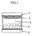
- FIG. 1 shows an example of a configuration of an electrochromic display device of the present invention.
- the organic-inorganic composite material of the present invention contains a metal oxide and a functional organic material located on the metal oxide, wherein the functional organic material and the metal oxide are bound via a silanol bond.
- the functional organic material and the metal oxide are strongly bound via the silanol bond, so that the organic-inorganic composite material having excellent durability can be obtained.
- the silanol bond is a bond represented by "-Si-O-", namely, a bond between a silicon atom and a metal oxide via an oxygen atom.
- the silanol bond is preferably formed by reacting a silane coupling agent with a metal oxide.
- a silanol bond can be easily formed by using a silane coupling agent.
- the silane coupling agent itself may have functionality. However, when the silane coupling agent has a reactive terminal, the functional organic material can be bound via the reactive terminal.
- the silane coupling agent may have a plurality of reactive terminals.
- the reactive terminal in the silane coupling agent may preferably have a structure selected from the following formulas. -Br --F, -Cl, -I, -OH, -NH 2 , -C ⁇ CH, -NCO
- the silane coupling agent is not particularly limited and may be appropriately selected according to the purpose, as long as it has a reactive terminal as expressed above and can form a silanol bond.
- Trialkoxysilane compounds, trichlorosilane compounds and monochlorosilane compounds are particularly preferred in terms of easy synthesis.
- Trichlorosilane compounds are preferred because they are highly reactive and adsorbed on various metal oxides in a short time.
- Trialkoxysilane compounds are preferred in terms of easy control of reaction progress because they have relatively low reactivity.
- Monochlorosilane compounds are preferred in terms of easy control of the amount of adsorption to a metal oxide because they can prevent the silane coupling agent from oligomerization.
- the silane coupling agent is not particularly limited and may be appropriately selected according to the purpose. Examples thereof include 1,2-dichloroethyltrichlorosilane, 1,2-dibromoethyltrichlorosilane, 10-undecenyldimethylchlorosilane, 11-bromoundecyldimethylchlorosilane, 11-bromoundecyltrichlorosilane, 11-bromoundecyltrimethoxysilane, 1-chloroethyltrichlorosilane, 2-(3,4-epoxycyclohexylethyl)trimethoxysilane, 2-(4-pyridylethyl)triethoxysilane, 2-aminoethylaminomethyltrimethoxysilane, 2-chloloethyltrichlorosilane, 2-cyanoethyltrichlorosilane, 3-(2,4-din
- the silanol bond binding the functional organic material and the metal oxide is confirmed by detecting a silanol bond or the like in the functional organic material.
- the silanol bond is detected by X-ray photoelectron spectroscopy or infrared spectroscopy.
- a silanol bond or a functional organic material bound via a silanol bond can be confirmed by detecting a peak derived from silicon atoms, the functional organic material, silane coupling agent, or reactive terminal of the silane coupling agent by X-ray photoelectron spectroscopy.
- a silanol bond or a functional organic material bound via a silanol bond can be also confirmed by detecting a peak derived from the silanol bond (namely, a bond between silicon and a metal oxide), or a peak derived from the functional organic material, silane coupling agent or reactive terminal of the silane coupling agent by infrared spectroscopy.
- the metal oxide is not particularly limited in its nature and form and may be appropriately selected according to the purpose, as long as it can form a silanol bond with a functional organic material.
- a metal oxide suitable for the property of functional organic material is suitably used.
- the metal oxide is not particularly limited and may be appropriately selected according to the purpose. Examples thereof include titanium oxides, zinc oxides, tin oxides, alumina, zirconia, ceria, silica, yttria, boronia, magnesium oxides, strontium titanate, potassium titanate, barium titanate, calcium titanate, calcia, ferrite, hafnia, tungsten trioxides, iron oxides, copper oxides, nickel oxides, cobalt oxides, barium oxides, strontium oxides, vanadium oxides, indium oxides, barium titanate, aluminosilica, calcium phosphate and aluminosilicate. These may be used alone or in combination.
- titanium oxides zinc oxides, tin oxides, alumina, zirconia, iron oxides, magnesium oxides, indium oxides and tungsten trioxides are preferable. Titanium oxides are most preferable in terms of electrical and physical properties.
- the average primary particle diameter of the metal oxide is not particularly limited and may be appropriately selected according to the purpose It is preferably 200 nm or less, and more preferably 30 nm or less.
- the metal oxide has an average primary particle diameter of 200 nm or less, the specific surface area of the metal oxide becomes large enough to be able to adsorb and bind more chromophores, and the metal oxide much excels in color developing property.
- the metal oxide has an average primary particle diameter of 30 nm or less, light transmission through the metal oxide significantly increases, and the metal oxide much excels in color developing property.
- the functional organic material preferably has any one of electrochromic properties and photoelectric conversion function.
- the functional organic material can be used for various applications such as in electrochromic display devices and photoelectric conversion devices.
- a material which has a chromophore which may change its color tone by electricity and directly and/or indirectly forms a silanol bond with a metal oxide may be used.
- the compound having a chromophore is not particularly limited and may be appropriately selected according to the purpose.
- Examples thereof include azobenzene compounds, anthraquinone compounds, diarylethene compounds, dihydropyrene compounds, spirooxazine compounds, spirothiopyran compounds, spiropyran compounds, thioindigo compounds, tetrathiafulvalene compounds, triphenylmethane compounds, triphenylamine compounds, naphthopyran compounds, viologen compounds, pyrazoline compounds, phenazine compounds, phenylenediamine compounds, phenoxazine compounds, phenothiazine compounds, phthalocyanine compounds, fluorane compounds, fulgide compounds, benzopyrane compounds and metallocene compounds. Of these, viologen compounds are particularly preferred in terms of excellent durability.
- viologen compounds include 1-ethyl-4-(4-pyridyl)pyridinium chloride, 1-hexyl-4-(4-pyridyl)pyridinium bromide, 1-cyanophenyl-4-(4-pyridyl)pyridinium chloride, 1-ethyl-1'-carboxy-4,4'-bipyridinium dichloride, 1-methyl-1'-carboxyethyl-4,4'-bipyridinium dichloride, 1,1'-bis(carboxymethyl)-4,4'-bipyridinium dichloride, ⁇ -(10-phenothiazinyl)propionate, ⁇ -(10-phenothiazinyl)ethylphosphonate, ⁇ -(10-phenothiazinyl)methylslufonate, hydroxyanthiaquinone-1-sulfonate, hydroxyanthraquinone-2-sulfonate, tripheny
- the functional organic material having photoelectric conversion function is not particularly limited and may be appropriately selected according to the purpose, as long as it has absorption in at least one of the visible light band and infrared light band, and can directly or indirectly form a silanol bond with a metal oxide.
- Examples thereof include organic dyes such as coumarin compounds, azo compounds, cyanine compounds, spiropyran compounds, xanthene compounds; metal complex dyes such as ruthenium complexes, and quaternary salt compounds thereof, porphyrin compounds, phthalocyanine compounds, and mixtures thereof.
- cyanidin 3-glucosidetetrasulfonated gallium phthalocyanine cis-di(thiocyanato)-bis(2,2'-bipyridyl-4,4'-dicarboxylic acid)-ruthenium(II), cis-di(thiocyanato)-(2,2'-bipyridyl-4,4'-dicarboxylic acid)(4,4'-ditridecyl-2,2'-bipyridyl)-ruthenium(II), cis-di(thiocyanato)-bis(2,2'-bipyridyl-4-carboxylate-4'-carboxylic acid)-ruthenium(II), cis-di(thiocyanato)-(2,2'-bipyridyl-4,4'-dicarboxylic acid)(4-methyl-4'-hexadecyl-2,2'-bi
- a method for producing an organic-inorganic composite material of the present invention is as follows: a silane coupling agent having a functional group reactive with a functional organic material is reacted with a metal oxide, and then a functional organic material is reacted with the functional group so as to bind the functional organic material and the metal oxide via a silanol bond to produce the organic-inorganic composite material.
- a method for producing an organic-inorganic composite material is specifically exemplified as follows: a dispersion of titanium oxide fine particles as a metal oxide is applied onto a glass substrate by spin coating using a mask, the glass substrate having a transparent electrode film made of tin oxide on the entire surface, to deposit a titanium oxide layer. Next, the electrode having the titanium oxide layer is immersed in 5 mass% 3-bromopropyltriethoxysilane toluene solution, after addition of triethylamine, and left to stand for 24 hours, and then washed and dried.
- the obtained electrode is immersed in 5 mass% aqueous 1-ethyl-4-(4-pyridyl)pyridinium chloride solution at 80°C for 100 hours, and then washed and dried to obtain an organic-inorganic composite material, in which 1-ethyl-4-(4-pyridyl)pyridinium chloride as a functional organic material and a titanium oxide are bound via a silanol bond.
- the method for producing an organic-inorganic composite material of the present invention can easily produce an organic-inorganic composite material, in which the functional organic material and the metal oxide are strongly bound via a silanol bond, and the functional organic material can be easily and strongly attached on an inorganic material even though the functional organic material has a structure which was hard to be attached thereon, and can provide a novel functional material having an excellent function.
- a display electrode for electrochromic display device of the present invention contains an electrode and a color developing layer on the electrode, wherein the color developing layer contains the organic-inorganic composite material of the present invention having electrochromic properties. Adoption of such a configuration enables electrons to move easily between electrodes, thus the display electrode for electrochromic display device is excellent in response and durability.
- the electrode contains a substrate for display electrode, electrode for display electrode and color developing layer, and the substrate for display electrode may function as the electrode for display electrode.
- Examples of materials for the substrate include glass; and plastics such as acrylic resins, polycarbonate resins and epoxy resins.
- the materials for the electrode are not particularly limited and may be appropriately selected according to the purpose, as long as they have electrical conductivity. Examples thereof include ITO and FTO (for transparent electrodes); and metals such as copper, zinc, gold, platinum, iron and aluminium. Of these, ITO and FTO (for transparent electrodes) are particularly preferred in terms of visibility from an electrode side in the electrochromic display device.
- the electrochromic display device of the present invention contains a display electrode for electrochromic display device of the present invention, a counter electrode arranged to face the display electrode for electrochromic display device at a distance, an electrolyte layer arranged between the display electrode and counter electrode, and further contains other components as necessary.
- the counter electrode has a substrate and electrode, and the substrate may function as the electrode.
- the electrolyte layer is arranged between the display electrode and the counter electrode.
- the electrolyte is not particularly limited and may be appropriately selected from known nonaqueous electrolytes and aqueous electrolytes according to the purpose. Examples thereof include organic electrolytic solutions, polymer solid electrolytes, gel electrolytes and ionic liquids.
- a white reflective layer containing white titanium oxide fine particles is preferably provided.
- the visibility of the electrochromic display device of the present invention is improved.
- FIG. 1 shows an example of a configuration of an electrochromic display device of the present invention.
- the configuration of the electrochromic display device of the present invention is not limited to FIG. 1 .
- 1, 2, 3, 4 and 5 respectively denote a display electrode, a color developing layer containing an organic-inorganic composite material having electrochromic properties of the present invention, an electrolyte, a white reflective layer and a counter electrode.
- An electrode for photoelectric conversion device of the present invention contains an electrode, and a photoelectric conversion layer formed on the electrode, wherein the photoelectric conversion layer contains the organic-inorganic composite material of the present invention. Adoption of such a configuration enables electrons to move easily between electrodes, thus the electrode for photoelectric conversion device is excellent in light conversion efficiency and durability.
- the electrode has a substrate for photoelectric conversion, electrode for photoelectric conversion and photoelectric conversion layer, and the substrate for photoelectric conversion may function as the electrode for photoelectric conversion.
- Examples of materials for the substrate include glass; and plastics such as acrylic resins, polycarbonate resins and epoxy resins.
- the material for the electrode is not particularly limited and may be appropriately selected according to the purpose, as long as it has electrical conductivity. Examples thereof include ITO and FTO (for transparent electrodes); and metals such as copper, zinc, gold, platinum, iron and aluminium. Of these, ITO and FTO (for transparent electrodes) are particularly preferred because they enable to receive light from the electrode side in the photoelectric conversion device.
- the photoelectric conversion device of the present invention contains an electrode for photoelectric conversion device of the present invention, a counter electrode arranged to face the electrode for photoelectric conversion device at a distance, and an electrolyte layer arranged between the electrode and counter electrode, and further contains other components as necessary.
- the counter electrode has a substrate and an electrode, and the substrate may function as the electrode
- the electrolyte layer is arranged between the electrode for the photoelectric conversion device and the counter electrode.
- An electrolyte is not particularly limited and may be appropriately selected from known nonaqueous electrolytes and aqueous electrolytes according to the purpose. Examples thereof include organic electrolytic solutions, polymer solid electrolytes, gel electrolytes and ionic liquids.
- a dispersion of titanium oxide fine particles (TKS-203 manufactured by Tayca Co., Ltd, average primary particle diameter: 6 nm) was applied onto a portion (area: 1 cm 2 ) of a glass substrate by spin coating using a mask, the glass substrate having a transparent electrode film made of tin oxide on the entire surface, and heated at 450°C for 1 hour to deposit a titanium oxide layer having a thickness of 2 ⁇ m.
- the electrode having the titanium oxide layer was immersed in 100 ml of 5% 3-bromopropyltriethoxysilane toluene solution, and 5 g of triethylamine was added therein, left to stand for 24 hours, and then washed and dried.
- the obtained electrode was immersed in 5% aqueous 1-ethyl-4-(4-pyridyl)pyridinium chloride solution at 80°C for 100 hours, and then washed and dried to prepare a display electrode.
- the obtained dispersion was applied over an entire surface of a zinc plate having a thickness of 0.2 mm using a wire bar, and dried to prepare a counter electrode.
- the obtained counter electrode had a thickness of 5 ⁇ m, and exhibited a white color similar to paper.
- the display electrode and the counter electrode were bonded together with spacers of 50 ⁇ m in thickness interposed between them to prepare a cell. Subsequently, an electrolyte solution was prepared by dissolving lithium perchlorate in propylene carbonate to a concentration of 0.2M, and sealed in the cell to produce an electrochromic display device.
- An electrochromic display device was produced in the same manner as in Example 1, except that 1-ethyl-4-(4-pyridyl)pyridinium chloride in Example 1 was changed to 1-hexyl-4-(4-pyridyl)pyridinium bromide.
- An electrochromic display device was produced in the same manner as in Example 1, except that a display electrode prepared as described below was used.
- a dispersion of titanium oxide fine particles (TKS-203 manufactured by Tayca Co., Ltd, average primary particle diameter: 6 nm) was applied onto a portion (area: 1 cm 2 ) of a glass substrate by spin coating using a mask, the glass substrate having a transparent electrode film made of tin oxide on the entire surface, and heated at 450°C for 1 hour to deposit a titanium oxide layer having a thickness of 2 ⁇ m.
- the electrode having the titanium oxide layer was immersed in 0.2% 3-bromopropyl trichlorosilane toluene solution for 2 hours, and then washed and dried.
- the obtained electrode was immersed in 5% aqueous 1-ethyl-4-(4-pyridyl)pyridinium chloride solution at 80°C for 100 hours, and then washed and dried to prepare a display electrode.
- a dispersion of titanium oxide fine particles (TKS-203 manufactured by Tayca Co., Ltd, average primary particle diameter: 6 nm) was applied onto a portion (area: 1 cm 2 ) of a glass substrate by spin coating using a mask, the glass substrate having a transparent electrode film made of tin oxide on the entire surface, and heated at 450°C for 1 hour to deposit a titanium oxide layer having a thickness of 2 ⁇ m.
- the electrode having the titanium oxide layer was immersed in 0.2% 3-bromopropyltrichlorosilane toluene solution for 1 hour, and then washed and dried.
- the obtained electrode was immersed in 5% 4-4'-bipyridyl toluene solution at 80°C for 10 hours, and then washed and dried.
- the electrode was immersed in 10% 2-bromoethane toluene solution at 80°C for 10 hours, and then washed and dried to prepare a display electrode.
- a counter electrode was prepared in the same manner as in Example 1.
- the display electrode and the counter electrode were bonded together with spacers of 50 ⁇ m in thickness interposed between them to prepare a cell. Subsequently, an electrolyte solution was prepared by dissolving lithium perchlorate in acetonitrile to a concentration of 0.2M, and sealed in the cell to produce an electrochromic display device.
- An electrochromic display device was produced in the same manner as in Example 4, except that 3-bromopropyltrichlorosilane in Example 4 was changed to 11-bromoundecyltrichlorosilane.
- a dispersion of titanium oxide fine particles (TKS-203 manufactured by Tayca Co., Ltd, average primary particle diameter: 6 nm) was applied onto a portion (area: 1 cm 2 ) of a glass substrate by spin coating using a mask, the glass substrate having a transparent electrode film made of tin oxide on the entire surface, and heated at 450°C for 1 hour to deposit a titanium oxide layer having a thickness of 2 ⁇ m.
- tris(p-trichlorosilylpropylphenyl)amine is an electrochromic dye which binds to a metal oxide by silane bonding and has chromic function.
- an electrochromic display device was produced by preparing a counter electrode and electrolytic solution in the same manner as in Example 1
- An electrochromic display device was produced in the same manner as in Example 4, except that 3-bromopropyltrichlorosilane in Example 4 was changed to 11-bromoundecyldimethylchlorosilane.
- An electrochromic display device was produced in the same manner as in Example 1, except that a display electrode prepared as described below was used.
- a compound expressed by the following formula as an organic electrochromic compound was dissolved in water to prepare a 0.02M solution of the organic electrochromic compound.
- a dispersion of titanium oxide fine particles (TKS-203 manufactured by Tayca Co., Ltd., average primary particle diameter: 6 nm) was applied onto a portion (area: 1 cm 2 ) of a glass substrate by spin coating using a mask, the glass substrate having a transparent electrode film made of tin oxide on the entire surface, and heated at 450°C for 1 hour to deposit a titanium oxide layer having a thickness of 2 ⁇ m.
- the electrode having the titanium oxide layer was immersed in a solution of organic electrochromic compound expressed by the above formula for 24 hours, and then washed and dried to prepare a display electrode.
- An electrochromic display device was produced in the same manner as in Example 1, except that a display electrode prepared as described below was used.
- a compound expressed by the following formula as the organic electrochromic compound was dissolved in water to prepare a 0.02M solution of the organic electrochromic compound.
- a dispersion of titanium oxide fine particles (TKS-203 manufactured by Tayca Co., Ltd., average primary particle diameter: 6 nm) was applied onto a portion (area: 1 cm 2 ) of a glass substrate by spin coating using a mask, the glass substrate having a transparent electrode film made of tin oxide on the entire surface, and heated at 450°C for 1 hour to deposit a titanium oxide layer having a thickness of 2 ⁇ m.
- the electrode having the titanium oxide layer was immersed in a solution of the organic electrochromic compound expressed by the above formula for 24 hours, and then washed and dried to prepare a display electrode.
- An electrochromic display device was produced in the same manner as in Comparative Example 1, except that the organic electrochromic compound in Comparative Example 1 was changed to a compound expressed by the following formula.
- the color developing and erasing properties of each electrochromic display device was evaluated by measuring reflectance by irradiating with diffusion light using a spectrocolorimeter (LCD-5000 manufactured by Otsuka Electronics Co., Ltd.). The results are shown in Table 1.
- the reflectance in Table 1 is a value obtained by dividing a reflected light of each of the prepared electrochromic display device by a reference output and expressed in percentage (%).
- the reference output was a reflected light occurring when a standard white plate was irradiated with light at an incident angle of 30 degrees. Note that when the color developing property was good, the reflectance was decreased, and when color developing property was degraded, the reflectance was increased.
- a voltage was applied using a function generator FG-02 (manufactured by Toho Technical Research Co., Ltd.).
- each electrochromic display device When the reflectance was measured without applying voltage, each electrochromic display device showed a high value of about 60%.
- the reflectance was measured by irradiating a diffusion light using a spectrocolorimeter (LCD-5000 manufactured by Otsuka Electronics Co., Ltd.).
- titanium oxide P-25 manufactured by NIPPON AEROSIL CO., LTD.
- 6.0 g of water 6.0 g of water
- 0.2 ml of acetylacetone 0.1 g of' a surfactant (Triton-X100 manufactured by Sigma-Aldrich Cho United States) were loaded and dispersed for 2 hours by a paint shaker.
- 1.0 g of 20 % polyethylene glycol manufactured by Wako Pure Chemical Industries, Ltd., mass average molecular weight: 20,000 was added therein to prepare a titanium oxide paste.
- the titanium oxide paste was uniformly applied onto a portion (area: 1 cm 2 ) of a glass substrate by spin coating using a mask, the glass substrate having a transparent electrode film made of tin oxide on the entire surface, and naturally dried and then baked at 450°C for 1 hour to deposit a titanium oxide film having a thickness of 10 ⁇ m.
- the electrode was immersed in 200 ml of 5% 3-aminopropyltriethoxysilane toluene solution, and 2 g of triethylamine was added therein, refluxed for 8 hours and then washed and dried.
- the electrode was placed in a container, 5.7 g of Coumarin 343, 2.5g of N,N'-diisopropylcarbodiimide, 2.7g of N,N'-diisopropylcarbodiimide, and 200g of tetrahydrofuran (THF) were added therein, refluxed for 2 hours and then washed and dried to prepare a photoelectric conversion electrode.
- THF tetrahydrofuran
- a platinum film was deposited by vacuum evaporation onto a glass substrate having a transparent electrode film made of tin oxide on the entire surface so as to have a thickness of 20 nm to prepare a counter electrode.
- the photoelectric conversion electrode and the counter electrode were disposed via insulating spacers of 10 ⁇ m in thickness interposed between them, an oxidation-reduction electrolyte solution prepared by adding iodine and tetrapropylammonium iodide in a mixed solvent of ethylene carbonate and acetonitrile, was poured therein, and then sealed with an epoxy adhesive to produce a photoelectric conversion device.
- the obtained photoelectric conversion device had a photoelectric conversion efficiency of 2.5% under irradiation with pseudo sunlight (AM1.5, 100mW/cm 2 ). Moreover, after the photoelectric conversion device was left to stand for 1 week at room temperature, it had a photoelectric conversion efficiency of 2.5% under irradiation with the pseudo sunlight.
- titanium oxide P-25 manufactured by NIPPON AEROSIL CO., LTD.
- water 6.0g
- 0.2 ml of acetylacetone 0.1 g
- a surfactant Triton-X100 manufactured by Sigma-Aldrich Co.. United States
- 1.0g of 20% polyethylene glycol manufactured by Wako Pure Chemical Industries, Ltd., mass average molecular mass: 20,000 was added therein to prepare a titanium oxide paste.
- the titanium oxide paste was uniformly applied onto a portion (area: 1 cm 2 ) of a glass substrate by spin coating using a mask, the glass substrate having a transparent electrode film made of tin oxide on the entire surface, and naturally dried and then baked at 450°C for 1 hour to deposit a titanium oxide film having a thickness of 10 ⁇ m.
- the electrode was immersed in a 2% ethanol solution of Coumarin 343, refluxed for 2 hours and then washed and dried to prepare a photoelectric conversion electrode.
- a counter electrode was prepared in the same manner as in Example 8.
- a photoelectric conversion device was produced in the same manner as in Example 8.
- the obtained photoelectric conversion device had a photoelectric conversion efficiency of 2.0% under irradiation with pseudo sunlight (AM1.5, 100mW/cm 2 ). Moreover, after the photoelectric conversion device was left to stand for 1 week at room temperature, it had a photoelectric conversion efficiency of 0.5% under irradiation with the pseudo sunlight.
- An electrochromic display device using the organic-inorganic composite material of the present invention is excellent in response and durability, and can be suitably used for, for example, electronic paper, electronic albums and various display devices.
- the photoelectric conversion device using the organic-inorganic composite material of the present invention is excellent in light conversion efficiency and durability, and can be suitably used for, for example, dye-sensitized solar batteries.
Landscapes
- Physics & Mathematics (AREA)
- Nonlinear Science (AREA)
- Chemical & Material Sciences (AREA)
- General Physics & Mathematics (AREA)
- Optics & Photonics (AREA)
- Engineering & Computer Science (AREA)
- Materials Engineering (AREA)
- Organic Chemistry (AREA)
- Electrochromic Elements, Electrophoresis, Or Variable Reflection Or Absorption Elements (AREA)
- Laminated Bodies (AREA)
Abstract
Description
- The present invention relates to an organic-inorganic composite material usable as an electrochromic display device and photoelectric conversion device, and a method for producing the organic-inorganic composite material, and a functional electrode and functional device using the organic-inorganic composite material.
- Recently, much research effort has been made to electronic paper as an electronic medium that is expected to displace paper. In contrast to conventional displays including CRTs and liquid crystal displays (LCDs), electronic paper is required to have the following characteristics: (1) being a flexible reflective display device; (2) high white reflectance and contrast ratio; (3) high definition display; (4) memory effect in display; (5) low-voltage drive capability; (6) slimness and lightness; (7) inexpensiveness, and the like. For example, an electrochromic display device utilizing color development/color erasure of an electrochromic compound has been researched and developed in wide ranges such as material development, device design and the like as a candidate for electronic paper, because it is a reflective display device, has memory effect and can be driven at low voltage. Various colors can be developed according to material structure, thus it is expected to be used also as a multiple color display device.
- As a material for realizing an electronic device such as those typified by electronic paper, an organic-inorganic composite material has been actively researched. For example,
Patent Literature 1 proposes a material in which an electrochromic compound is adsorbed on a nanocrystalline layer deposited on an electrode. InPatent Literature 1, a terminal of a functional organic material such as acidic groups of a carboxylic acid, salicylic acid and the like is adsorbed to hydroxyl groups of inorganic fine particles, thus an organic compound can be adsorbed on the inorganic fine particles, but its bonding force is not so strong that the bonds between the organic compound and the inorganic fine particles are easily broken when an electrochromic device is produced, repeatedly used, or used under alkaline conditions, and the device has poor durability. - On the other hand, a dye-sensitized solar cell, in which a colored organic compound having photosensitization function is adsorbed to inorganic fine particles, proposed by Grätzel et al. (see Non-Patent Literature 1), has the same configuration as the electrochromic device. However, as it stands, there is a problem of poor durability as with the electrochromic device.
- Patent Literature 1: Japanese Patent Application Laid-Open (JP-A) No.
2000-506629 - Non-Patent Literature 1: Nature, 353, 737 (1991)
- An object of the present invention is to provide an organic-inorganic composite material having excellent durability, in which a metal oxide and a functional organic material are strongly bound, a method for producing the organic-inorganic composite material, a functional electrode such as an electrode for electrochromic display device and electrode for photoelectric conversion device using the organic-inorganic composite material, and a functional device such as an electrochromic display device and photoelectric conversion device, which uses the functional electrode and has excellent initial color developing property and color developing stability over time.
- To solve the aforementioned problems, the inventors of the present invention have diligently studied and found that the problems can be effectively solved by binding a metal oxide and a functional organic material via a silanol bond.. In this case, the silanol bond is preferably formed by reacting a silane coupling agent with the metal oxide Conventionally, the surface treatment of inorganic fine particles using an organic compound has been widely performed. For example, Japanese Patent Application Laid-Open (JP-A) No.
2004-191418 - Note that the functional organic material of the present invention means an organic composition having at least any one of a photoelectric conversion function and chromic function and may form a complex with other organic compounds or inorganic compounds, and is of low molecular or high molecular.
- The present invention is based on the findings by the inventors of the present invention, and means for solving the aforementioned problems are described below.
- <1> An organic-inorganic composite material containing a metal oxide, and a functional organic material located on the metal oxide, wherein the functional organic material and the metal oxide are bound via a silanol bond.
- <2> The organic-inorganic composite material according to <1>, wherein the silanol bond is formed by reacting a silane coupling agent with the metal oxide.
- <3> The organic-inorganic composite material according to <2>, wherein the silane coupling agent has a reactive terminal.
- <4> The organic-inorganic composite material according to <3>, wherein the reactive terminal has a structure selected from the following formulas: -Br, -F ,

- <5> The organic-inorganic composite material according to any one of <2> to <4>, wherein the silane coupling agent is a trichlorosilane compound.
- <6> The organic-inorganic composite material according to any one of <2> to <4>, wherein the silane coupling agent is a trialkoxysilane compound.
- <7> The organic-inorganic composite material according to any one of <2> to <4>, wherein the silane coupling agent is a monochlorosilane compound.
- <8> The organic-inorganic composite material according to any one of <1> to <7>, wherein the functional organic material has electrochromic properties.
- <9> The organic-inorganic composite material according to any one of <1> to <7>, wherein the functional organic material has photoelectric conversion function
- <10> A method for producing the organic-inorganic composite material according to any one of <1> to <9>, including reacting a silane coupling agent having a functional group reactive with a functional organic material with a metal oxide; and reacting the functional organic material with the functional group so as to bind the functional organic material and the metal oxide via a silanol bond.
- <11> A display electrode for electrochromic display device containing an electrode and a color developing layer formed on the electrode, wherein the color developing layer contains the organic-inorganic composite material according to <8>.
- <12> The display electrode for electrochromic display device according to <11>, wherein the electrode is a transparent electrode.
- <13> An electrochromic display device containing the display electrode for electrochromic display device according to any one of < 11> to <12>, a counter electrode arranged to face the display electrode for electrochromic display device at a distance, and an electrolyte layer between the display electrode and the counter electrode.
- <14> The electrochromic display device according to <13>, further containing a white reflective layer which contains white titanium oxide fine particles.
- <15> An electrode for photoelectric conversion device containing an electrode and a photoelectric conversion layer formed on the electrode, wherein the photoelectric conversion layer contains the organic-inorganic composite material according to <9>.
- <16> A photoelectric conversion device containing the electrode for photoelectric conversion device according to <15>, a counter electrode arranged to face the electrode for photoelectric conversion device at a distance, and an electrolyte layer between the electrode for photoelectric conversion device and the counter electrode.
-
FIG. 1 shows an example of a configuration of an electrochromic display device of the present invention. - The organic-inorganic composite material of the present invention contains a metal oxide and a functional organic material located on the metal oxide, wherein the functional organic material and the metal oxide are bound via a silanol bond. Thus, the functional organic material and the metal oxide are strongly bound via the silanol bond, so that the organic-inorganic composite material having excellent durability can be obtained.
- The silanol bond is a bond represented by "-Si-O-", namely, a bond between a silicon atom and a metal oxide via an oxygen atom. The silanol bond is preferably formed by reacting a silane coupling agent with a metal oxide. Thus, a silanol bond can be easily formed by using a silane coupling agent.
- In the organic-inorganic composite material of the present invention, the silane coupling agent itself may have functionality. However, when the silane coupling agent has a reactive terminal, the functional organic material can be bound via the reactive terminal. The silane coupling agent may have a plurality of reactive terminals.
- The reactive terminal in the silane coupling agent may preferably have a structure selected from the following formulas. -Br --F,

- The silane coupling agent is not particularly limited and may be appropriately selected according to the purpose, as long as it has a reactive terminal as expressed above and can form a silanol bond. Trialkoxysilane compounds, trichlorosilane compounds and monochlorosilane compounds are particularly preferred in terms of easy synthesis. Trichlorosilane compounds are preferred because they are highly reactive and adsorbed on various metal oxides in a short time. Trialkoxysilane compounds are preferred in terms of easy control of reaction progress because they have relatively low reactivity. Monochlorosilane compounds are preferred in terms of easy control of the amount of adsorption to a metal oxide because they can prevent the silane coupling agent from oligomerization.
- The silane coupling agent is not particularly limited and may be appropriately selected according to the purpose. Examples thereof include 1,2-dichloroethyltrichlorosilane, 1,2-dibromoethyltrichlorosilane, 10-undecenyldimethylchlorosilane, 11-bromoundecyldimethylchlorosilane, 11-bromoundecyltrichlorosilane, 11-bromoundecyltrimethoxysilane, 1-chloroethyltrichlorosilane, 2-(3,4-epoxycyclohexylethyl)trimethoxysilane, 2-(4-pyridylethyl)triethoxysilane, 2-aminoethylaminomethyltrimethoxysilane, 2-chloloethyltrichlorosilane, 2-cyanoethyltrichlorosilane, 3-(2,4-dinitrophenylamino)propyltriethoxysilane, 3-(trihydroxysilyl)-1-propane-sulphonic acid, 3-aminopropyltriethoxysilane, 3-aminopropyltrimethoxysilane, 3-allylaminopropyltrimethoxysilane, 3-isocyanatepropyldimethylchlorosilane, 3-isocyanatepropyltriethoxysilane, 3-isocyanatepropyltrimethoxysilane, 3-chloropropyltriethoxysilane, 3-chloropropyltrichlorosilane, 3-cyanopropyltrichlorosilane, 3-bromopropyltriethoxysilane, 3-bromopropyltrichlorosilane, 3-mercaptopropyltrimethoxysilane, 3-mercaptopropylmethyldimethoxysilane, 4-(2-(trichlorosilyl)ethyl)pyridine, 4-chlorophenylchlorosilane, 4-chlolophenyltriethoxysilane, 4-chlorophenyltrimethoxysilane, 7-octenyltrichlorosilane, N-methylaminopropyltrimethoxysilane, allyltrichlorosilane, ureidopropyltriethoxysilane, chloromethyltriethoxysilane, chloromethyltrichlorosilane, chloromethyltrimethoxysilane, trimethoxyvinylsilane, vinyltrichlorosilane and mercaptomethyltrimethoxysilane. These may be used alone or in combination.
- The silanol bond binding the functional organic material and the metal oxide is confirmed by detecting a silanol bond or the like in the functional organic material. For example, the silanol bond is detected by X-ray photoelectron spectroscopy or infrared spectroscopy. Specifically, a silanol bond or a functional organic material bound via a silanol bond can be confirmed by detecting a peak derived from silicon atoms, the functional organic material, silane coupling agent, or reactive terminal of the silane coupling agent by X-ray photoelectron spectroscopy. Alternatively, a silanol bond or a functional organic material bound via a silanol bond can be also confirmed by detecting a peak derived from the silanol bond (namely, a bond between silicon and a metal oxide), or a peak derived from the functional organic material, silane coupling agent or reactive terminal of the silane coupling agent by infrared spectroscopy.
- The metal oxide is not particularly limited in its nature and form and may be appropriately selected according to the purpose, as long as it can form a silanol bond with a functional organic material. A metal oxide suitable for the property of functional organic material is suitably used.
- The metal oxide is not particularly limited and may be appropriately selected according to the purpose. Examples thereof include titanium oxides, zinc oxides, tin oxides, alumina, zirconia, ceria, silica, yttria, boronia, magnesium oxides, strontium titanate, potassium titanate, barium titanate, calcium titanate, calcia, ferrite, hafnia, tungsten trioxides, iron oxides, copper oxides, nickel oxides, cobalt oxides, barium oxides, strontium oxides, vanadium oxides, indium oxides, barium titanate, aluminosilica, calcium phosphate and aluminosilicate. These may be used alone or in combination. Of these, titanium oxides, zinc oxides, tin oxides, alumina, zirconia, iron oxides, magnesium oxides, indium oxides and tungsten trioxides are preferable. Titanium oxides are most preferable in terms of electrical and physical properties.
- The average primary particle diameter of the metal oxide is not particularly limited and may be appropriately selected according to the purpose It is preferably 200 nm or less, and more preferably 30 nm or less.
- When the metal oxide has an average primary particle diameter of 200 nm or less, the specific surface area of the metal oxide becomes large enough to be able to adsorb and bind more chromophores, and the metal oxide much excels in color developing property. When the metal oxide has an average primary particle diameter of 30 nm or less, light transmission through the metal oxide significantly increases, and the metal oxide much excels in color developing property.
- The functional organic material preferably has any one of electrochromic properties and photoelectric conversion function. Thus, the functional organic material can be used for various applications such as in electrochromic display devices and photoelectric conversion devices.
- As the functional organic material having electrochromic properties, a material which has a chromophore which may change its color tone by electricity and directly and/or indirectly forms a silanol bond with a metal oxide may be used. The compound having a chromophore is not particularly limited and may be appropriately selected according to the purpose. Examples thereof include azobenzene compounds, anthraquinone compounds, diarylethene compounds, dihydropyrene compounds, spirooxazine compounds, spirothiopyran compounds, spiropyran compounds, thioindigo compounds, tetrathiafulvalene compounds, triphenylmethane compounds, triphenylamine compounds, naphthopyran compounds, viologen compounds, pyrazoline compounds, phenazine compounds, phenylenediamine compounds, phenoxazine compounds, phenothiazine compounds, phthalocyanine compounds, fluorane compounds, fulgide compounds, benzopyrane compounds and metallocene compounds. Of these, viologen compounds are particularly preferred in terms of excellent durability.
- Examples of viologen compounds include 1-ethyl-4-(4-pyridyl)pyridinium chloride, 1-hexyl-4-(4-pyridyl)pyridinium bromide, 1-cyanophenyl-4-(4-pyridyl)pyridinium chloride, 1-ethyl-1'-carboxy-4,4'-bipyridinium dichloride, 1-methyl-1'-carboxyethyl-4,4'-bipyridinium dichloride, 1,1'-bis(carboxymethyl)-4,4'-bipyridinium dichloride, β-(10-phenothiazinyl)propionate, β-(10-phenothiazinyl)ethylphosphonate, β-(10-phenothiazinyl)methylslufonate, hydroxyanthiaquinone-1-sulfonate, hydroxyanthraquinone-2-sulfonate, triphenylpyrazoline, styrylpyrazoline and lanthanide-diphthalocyanine.
- The functional organic material having photoelectric conversion function is not particularly limited and may be appropriately selected according to the purpose, as long as it has absorption in at least one of the visible light band and infrared light band, and can directly or indirectly form a silanol bond with a metal oxide. Examples thereof include organic dyes such as coumarin compounds, azo compounds, cyanine compounds, spiropyran compounds, xanthene compounds; metal complex dyes such as ruthenium complexes, and quaternary salt compounds thereof, porphyrin compounds, phthalocyanine compounds, and mixtures thereof.
- Specific examples thereof include cyanidin 3-glucosidetetrasulfonated gallium phthalocyanine, cis-di(thiocyanato)-bis(2,2'-bipyridyl-4,4'-dicarboxylic acid)-ruthenium(II), cis-di(thiocyanato)-(2,2'-bipyridyl-4,4'-dicarboxylic acid)(4,4'-ditridecyl-2,2'-bipyridyl)-ruthenium(II), cis-di(thiocyanato)-bis(2,2'-bipyridyl-4-carboxylate-4'-carboxylic acid)-ruthenium(II), cis-di(thiocyanato)-(2,2'-bipyridyl-4,4'-dicarboxylic acid)(4-methyl-4'-hexadecyl-2,2'-bipyridyl)-ruthenium(II), 3-hydroxycarbonylcoumarin, 7-hydroxycarbonylcoumarin, 8-hydroxycarbonylcoumarin, Zn 5,10,15,20-tetracarboxyphenylporphyrin, and tetrasulfonated zinc porphyrin.
- A method for producing an organic-inorganic composite material of the present invention is as follows: a silane coupling agent having a functional group reactive with a functional organic material is reacted with a metal oxide, and then a functional organic material is reacted with the functional group so as to bind the functional organic material and the metal oxide via a silanol bond to produce the organic-inorganic composite material.
- Here, a method for producing an organic-inorganic composite material is specifically exemplified as follows: a dispersion of titanium oxide fine particles as a metal oxide is applied onto a glass substrate by spin coating using a mask, the glass substrate having a transparent electrode film made of tin oxide on the entire surface, to deposit a titanium oxide layer. Next, the electrode having the titanium oxide layer is immersed in 5 mass% 3-bromopropyltriethoxysilane toluene solution, after addition of triethylamine, and left to stand for 24 hours, and then washed and dried. The obtained electrode is immersed in 5 mass% aqueous 1-ethyl-4-(4-pyridyl)pyridinium chloride solution at 80°C for 100 hours, and then washed and dried to obtain an organic-inorganic composite material, in which 1-ethyl-4-(4-pyridyl)pyridinium chloride as a functional organic material and a titanium oxide are bound via a silanol bond.
- The method for producing an organic-inorganic composite material of the present invention can easily produce an organic-inorganic composite material, in which the functional organic material and the metal oxide are strongly bound via a silanol bond, and the functional organic material can be easily and strongly attached on an inorganic material even though the functional organic material has a structure which was hard to be attached thereon, and can provide a novel functional material having an excellent function.
- A display electrode for electrochromic display device of the present invention contains an electrode and a color developing layer on the electrode, wherein the color developing layer contains the organic-inorganic composite material of the present invention having electrochromic properties. Adoption of such a configuration enables electrons to move easily between electrodes, thus the display electrode for electrochromic display device is excellent in response and durability.
- The electrode contains a substrate for display electrode, electrode for display electrode and color developing layer, and the substrate for display electrode may function as the electrode for display electrode.
- Examples of materials for the substrate include glass; and plastics such as acrylic resins, polycarbonate resins and epoxy resins.
- The materials for the electrode are not particularly limited and may be appropriately selected according to the purpose, as long as they have electrical conductivity. Examples thereof include ITO and FTO (for transparent electrodes); and metals such as copper, zinc, gold, platinum, iron and aluminium. Of these, ITO and FTO (for transparent electrodes) are particularly preferred in terms of visibility from an electrode side in the electrochromic display device.
- The electrochromic display device of the present invention contains a display electrode for electrochromic display device of the present invention, a counter electrode arranged to face the display electrode for electrochromic display device at a distance, an electrolyte layer arranged between the display electrode and counter electrode, and further contains other components as necessary.
- The counter electrode has a substrate and electrode, and the substrate may function as the electrode.
- The electrolyte layer is arranged between the display electrode and the counter electrode. The electrolyte is not particularly limited and may be appropriately selected from known nonaqueous electrolytes and aqueous electrolytes according to the purpose. Examples thereof include organic electrolytic solutions, polymer solid electrolytes, gel electrolytes and ionic liquids.
- In the electrochromic display device, a white reflective layer containing white titanium oxide fine particles is preferably provided. By providing the white reflective layer, the visibility of the electrochromic display device of the present invention is improved.
- Here,
FIG. 1 shows an example of a configuration of an electrochromic display device of the present invention. However, the configuration of the electrochromic display device of the present invention is not limited toFIG. 1 . - In
FIG. 1, 1, 2, 3, 4 and 5 respectively denote a display electrode, a color developing layer containing an organic-inorganic composite material having electrochromic properties of the present invention, an electrolyte, a white reflective layer and a counter electrode. - An electrode for photoelectric conversion device of the present invention contains an electrode, and a photoelectric conversion layer formed on the electrode, wherein the photoelectric conversion layer contains the organic-inorganic composite material of the present invention. Adoption of such a configuration enables electrons to move easily between electrodes, thus the electrode for photoelectric conversion device is excellent in light conversion efficiency and durability.
- The electrode has a substrate for photoelectric conversion, electrode for photoelectric conversion and photoelectric conversion layer, and the substrate for photoelectric conversion may function as the electrode for photoelectric conversion.
- Examples of materials for the substrate include glass; and plastics such as acrylic resins, polycarbonate resins and epoxy resins.
- The material for the electrode is not particularly limited and may be appropriately selected according to the purpose, as long as it has electrical conductivity. Examples thereof include ITO and FTO (for transparent electrodes); and metals such as copper, zinc, gold, platinum, iron and aluminium. Of these, ITO and FTO (for transparent electrodes) are particularly preferred because they enable to receive light from the electrode side in the photoelectric conversion device.
- The photoelectric conversion device of the present invention contains an electrode for photoelectric conversion device of the present invention, a counter electrode arranged to face the electrode for photoelectric conversion device at a distance, and an electrolyte layer arranged between the electrode and counter electrode, and further contains other components as necessary.
- The counter electrode has a substrate and an electrode, and the substrate may function as the electrode
- The electrolyte layer is arranged between the electrode for the photoelectric conversion device and the counter electrode. An electrolyte is not particularly limited and may be appropriately selected from known nonaqueous electrolytes and aqueous electrolytes according to the purpose. Examples thereof include organic electrolytic solutions, polymer solid electrolytes, gel electrolytes and ionic liquids.
- Hereinafter, Examples of the present invention will be described, which however shall not be construed as limiting the scope of the present invention. All percentages and parts are by mass unless indicated otherwise.
- A dispersion of titanium oxide fine particles (TKS-203 manufactured by Tayca Co., Ltd, average primary particle diameter: 6 nm) was applied onto a portion (area: 1 cm2) of a glass substrate by spin coating using a mask, the glass substrate having a transparent electrode film made of tin oxide on the entire surface, and heated at 450°C for 1 hour to deposit a titanium oxide layer having a thickness of 2 µm.
- Next, the electrode having the titanium oxide layer was immersed in 100 ml of 5% 3-bromopropyltriethoxysilane toluene solution, and 5 g of triethylamine was added therein, left to stand for 24 hours, and then washed and dried. The obtained electrode was immersed in 5% aqueous 1-ethyl-4-(4-pyridyl)pyridinium chloride solution at 80°C for 100 hours, and then washed and dried to prepare a display electrode.
- In 10 ml of tetrahydrofuran solution, 5g of titanium oxide particles having a primary particle diameter of 300 nm (CR-50 manufactured by ISHIHARA SANGYO KAISHA, LTD.) and 1g of a polyester resin (FINEDIC M-8076 manufactured by DIC Corporation) in 50% methyl ethyl ketone (MEK) solution were dispersed to prepare a dispersion
- The obtained dispersion was applied over an entire surface of a zinc plate having a thickness of 0.2 mm using a wire bar, and dried to prepare a counter electrode. The obtained counter electrode had a thickness of 5µm, and exhibited a white color similar to paper.
- The display electrode and the counter electrode were bonded together with spacers of 50 µm in thickness interposed between them to prepare a cell. Subsequently, an electrolyte solution was prepared by dissolving lithium perchlorate in propylene carbonate to a concentration of 0.2M, and sealed in the cell to produce an electrochromic display device.
- An electrochromic display device was produced in the same manner as in Example 1, except that 1-ethyl-4-(4-pyridyl)pyridinium chloride in Example 1 was changed to 1-hexyl-4-(4-pyridyl)pyridinium bromide.
- An electrochromic display device was produced in the same manner as in Example 1, except that a display electrode prepared as described below was used.
- A dispersion of titanium oxide fine particles (TKS-203 manufactured by Tayca Co., Ltd, average primary particle diameter: 6 nm) was applied onto a portion (area: 1 cm2) of a glass substrate by spin coating using a mask, the glass substrate having a transparent electrode film made of tin oxide on the entire surface, and heated at 450°C for 1 hour to deposit a titanium oxide layer having a thickness of 2 µm.
- Next, the electrode having the titanium oxide layer was immersed in 0.2% 3-bromopropyl trichlorosilane toluene solution for 2 hours, and then washed and dried. The obtained electrode was immersed in 5% aqueous 1-ethyl-4-(4-pyridyl)pyridinium chloride solution at 80°C for 100 hours, and then washed and dried to prepare a display electrode.
- A dispersion of titanium oxide fine particles (TKS-203 manufactured by Tayca Co., Ltd, average primary particle diameter: 6 nm) was applied onto a portion (area: 1 cm2) of a glass substrate by spin coating using a mask, the glass substrate having a transparent electrode film made of tin oxide on the entire surface, and heated at 450°C for 1 hour to deposit a titanium oxide layer having a thickness of 2 µm.
- Next, the electrode having the titanium oxide layer was immersed in 0.2% 3-bromopropyltrichlorosilane toluene solution for 1 hour, and then washed and dried. The obtained electrode was immersed in 5% 4-4'-bipyridyl toluene solution at 80°C for 10 hours, and then washed and dried. Next, the electrode was immersed in 10% 2-bromoethane toluene solution at 80°C for 10 hours, and then washed and dried to prepare a display electrode.
- A counter electrode was prepared in the same manner as in Example 1.
- The display electrode and the counter electrode were bonded together with spacers of 50 µm in thickness interposed between them to prepare a cell. Subsequently, an electrolyte solution was prepared by dissolving lithium perchlorate in acetonitrile to a concentration of 0.2M, and sealed in the cell to produce an electrochromic display device.
- An electrochromic display device was produced in the same manner as in Example 4, except that 3-bromopropyltrichlorosilane in Example 4 was changed to 11-bromoundecyltrichlorosilane.
- A dispersion of titanium oxide fine particles (TKS-203 manufactured by Tayca Co., Ltd, average primary particle diameter: 6 nm) was applied onto a portion (area: 1 cm2) of a glass substrate by spin coating using a mask, the glass substrate having a transparent electrode film made of tin oxide on the entire surface, and heated at 450°C for 1 hour to deposit a titanium oxide layer having a thickness of 2 µm.
- Next, the electrode having the titanium oxide layer was immersed in 5% tris(p-trichlorosilylpropylphenyl)amine alcohol solution for 48 hours, and then washed and dried to prepare a display electrode.. Note that tris(p-trichlorosilylpropylphenyl)amine is an electrochromic dye which binds to a metal oxide by silane bonding and has chromic function.
- Next, an electrochromic display device was produced by preparing a counter electrode and electrolytic solution in the same manner as in Example 1
- An electrochromic display device was produced in the same manner as in Example 4, except that 3-bromopropyltrichlorosilane in Example 4 was changed to 11-bromoundecyldimethylchlorosilane.
- An electrochromic display device was produced in the same manner as in Example 1, except that a display electrode prepared as described below was used.
- A compound expressed by the following formula as an organic electrochromic compound was dissolved in water to prepare a 0.02M solution of the organic electrochromic compound.

- A dispersion of titanium oxide fine particles (TKS-203 manufactured by Tayca Co., Ltd., average primary particle diameter: 6 nm) was applied onto a portion (area: 1 cm2) of a glass substrate by spin coating using a mask, the glass substrate having a transparent electrode film made of tin oxide on the entire surface, and heated at 450°C for 1 hour to deposit a titanium oxide layer having a thickness of 2 µm.
- Next, the electrode having the titanium oxide layer was immersed in a solution of organic electrochromic compound expressed by the above formula for 24 hours, and then washed and dried to prepare a display electrode.
- An electrochromic display device was produced in the same manner as in Example 1, except that a display electrode prepared as described below was used.
- A compound expressed by the following formula as the organic electrochromic compound was dissolved in water to prepare a 0.02M solution of the organic electrochromic compound.

- A dispersion of titanium oxide fine particles (TKS-203 manufactured by Tayca Co., Ltd., average primary particle diameter: 6 nm) was applied onto a portion (area: 1 cm2) of a glass substrate by spin coating using a mask, the glass substrate having a transparent electrode film made of tin oxide on the entire surface, and heated at 450°C for 1 hour to deposit a titanium oxide layer having a thickness of 2 µm.
- Next, the electrode having the titanium oxide layer was immersed in a solution of the organic electrochromic compound expressed by the above formula for 24 hours, and then washed and dried to prepare a display electrode.
- An electrochromic display device was produced in the same manner as in Comparative Example 1, except that the organic electrochromic compound in Comparative Example 1 was changed to a compound expressed by the following formula.

- Next, the color developing and erasing properties and durability (color developing property over time) of the obtained electrochromic display devices were evaluated as follows. The results are shown in Table 1.
- The color developing and erasing properties of each electrochromic display device was evaluated by measuring reflectance by irradiating with diffusion light using a spectrocolorimeter (LCD-5000 manufactured by Otsuka Electronics Co., Ltd.). The results are shown in Table 1. The reflectance in Table 1 is a value obtained by dividing a reflected light of each of the prepared electrochromic display device by a reference output and expressed in percentage (%). The reference output was a reflected light occurring when a standard white plate was irradiated with light at an incident angle of 30 degrees. Note that when the color developing property was good, the reflectance was decreased, and when color developing property was degraded, the reflectance was increased. A voltage was applied using a function generator FG-02 (manufactured by Toho Technical Research Co., Ltd.).
- When the reflectance was measured without applying voltage, each electrochromic display device showed a high value of about 60%. The reflectance was measured by irradiating a diffusion light using a spectrocolorimeter (LCD-5000 manufactured by Otsuka Electronics Co., Ltd.).
- When the display electrode was connected to a negative electrode and the counter electrode was connected to a positive electrode (or the display electrode was connected to a positive electrode and the counter electrode was connected to a negative electrode), and a voltage of 2.5V was applied thereto, blue color was developed. When a voltage of -1.0V was sufficiently applied to the display electrode, the blue color was erased and white color appeared again. The color developing property was evaluated on the following evaluation criteria.
- A: Blue color developed only in a part of the titanium oxide layer in the display electrode.
- B: Blue color developed in a part of the titanium oxide layer and other parts in the display electrode.
- C: Color development was hardly observed.
- After each electrochromic display device was left to stand for 1 week, the color developing and erasing test was performed again and each white reflective layer was observed. By measuring reflectance, the color developing property over time was evaluated, thereby obtaining a result of the durability test.
Table 1 Initial After left for 1 week Color developing property reflectance (*1) Color developing property reflectance (*1) Example 1 A 11% A 12% Example 2 A 12% A 12% Example 3 A 9% A 10% Example 4 A 10% A 10% Example 5 A 11% A 11% Example 6 A 15% A 15% Example 7 A 13% A 13% Comparative Example 1 B 20% C 35% Comparative Example 2 C 24% C 40% Comparative Example 3 B 15% C 34% (*1): the reflectance in a part of the titanium oxide layer in the display electrode upon color development - In a vessel, 2 g of titanium oxide (P-25 manufactured by NIPPON AEROSIL CO., LTD.), 6.0 g of water, 0.2 ml of acetylacetone and 0.1 g of' a surfactant (Triton-X100 manufactured by Sigma-Aldrich Cho United States) were loaded and dispersed for 2 hours by a paint shaker. Next, 1.0 g of 20 % polyethylene glycol (manufactured by Wako Pure Chemical Industries, Ltd., mass average molecular weight: 20,000) was added therein to prepare a titanium oxide paste.
- The titanium oxide paste was uniformly applied onto a portion (area: 1 cm2) of a glass substrate by spin coating using a mask, the glass substrate having a transparent electrode film made of tin oxide on the entire surface, and naturally dried and then baked at 450°C for 1 hour to deposit a titanium oxide film having a thickness of 10 µm.
- Next, the electrode was immersed in 200 ml of 5% 3-aminopropyltriethoxysilane toluene solution, and 2 g of triethylamine was added therein, refluxed for 8 hours and then washed and dried.
- Next, the electrode was placed in a container, 5.7 g of Coumarin 343, 2.5g of N,N'-diisopropylcarbodiimide, 2.7g of N,N'-diisopropylcarbodiimide, and 200g of tetrahydrofuran (THF) were added therein, refluxed for 2 hours and then washed and dried to prepare a photoelectric conversion electrode.
- A platinum film was deposited by vacuum evaporation onto a glass substrate having a transparent electrode film made of tin oxide on the entire surface so as to have a thickness of 20 nm to prepare a counter electrode.
- The photoelectric conversion electrode and the counter electrode were disposed via insulating spacers of 10 µm in thickness interposed between them, an oxidation-reduction electrolyte solution prepared by adding iodine and tetrapropylammonium iodide in a mixed solvent of ethylene carbonate and acetonitrile, was poured therein, and then sealed with an epoxy adhesive to produce a photoelectric conversion device.
- The obtained photoelectric conversion device had a photoelectric conversion efficiency of 2.5% under irradiation with pseudo sunlight (AM1.5, 100mW/cm2). Moreover, after the photoelectric conversion device was left to stand for 1 week at room temperature, it had a photoelectric conversion efficiency of 2.5% under irradiation with the pseudo sunlight.
- In a vessel, 2g of titanium oxide (P-25 manufactured by NIPPON AEROSIL CO., LTD.), 6.0g of water, 0.2 ml of acetylacetone and 0.1 g of a surfactant (Triton-X100 manufactured by Sigma-Aldrich Co.. United States) were loaded and dispersed for 2 hours by a paint shaker. Next, 1.0g of 20% polyethylene glycol (manufactured by Wako Pure Chemical Industries, Ltd., mass average molecular mass: 20,000) was added therein to prepare a titanium oxide paste.
- The titanium oxide paste was uniformly applied onto a portion (area: 1 cm2) of a glass substrate by spin coating using a mask, the glass substrate having a transparent electrode film made of tin oxide on the entire surface, and naturally dried and then baked at 450°C for 1 hour to deposit a titanium oxide film having a thickness of 10 µm.
- Next, the electrode was immersed in a 2% ethanol solution of Coumarin 343, refluxed for 2 hours and then washed and dried to prepare a photoelectric conversion electrode.
- A counter electrode was prepared in the same manner as in Example 8.
- A photoelectric conversion device was produced in the same manner as in Example 8.
- The obtained photoelectric conversion device had a photoelectric conversion efficiency of 2.0% under irradiation with pseudo sunlight (AM1.5, 100mW/cm2). Moreover, after the photoelectric conversion device was left to stand for 1 week at room temperature, it had a photoelectric conversion efficiency of 0.5% under irradiation with the pseudo sunlight.
- An electrochromic display device using the organic-inorganic composite material of the present invention is excellent in response and durability, and can be suitably used for, for example, electronic paper, electronic albums and various display devices.
- The photoelectric conversion device using the organic-inorganic composite material of the present invention is excellent in light conversion efficiency and durability, and can be suitably used for, for example, dye-sensitized solar batteries.
Claims (16)
- An organic-inorganic composite material comprising:a metal oxide; anda functional organic material located on the metal oxide,wherein the functional organic material and the metal oxide are bound via a silanol bond.
- The organic-inorganic composite material according to Claim 1, wherein the silanol bond is formed by reacting a silane coupling agent with the metal oxide.
- The organic-inorganic composite material according to Claim 2, wherein the silane coupling agent has a reactive terminal.
- The organic-inorganic composite material according to Claim 3, wherein the reactive terminal has a structure selected from the following formulas: -Br, -F,

- The organic-inorganic composite material according to any one of Claims 2 to 4, wherein the silane coupling agent is a trichlorosilane compound.
- The organic-inorganic composite material according to any one of Claims 2 to 4, wherein the silane coupling agent is a trialkoxysilane compound.
- The organic-inorganic composite material according to any one of Claims 2 to 4, wherein the silane coupling agent is a monochlorosilane compound.
- The organic-inorganic composite material according to any one of Claims 1 to 7, wherein the functional organic material has electrochromic properties.
- The organic-inorganic composite material according to any one of' Claims 1 to 7, wherein the functional organic material has photoelectric conversion function.
- A method for producing the organic-inorganic composite material according to any one of Claims 1 to 9, comprising:reacting a silane coupling agent having a functional group reactive with a functional organic material with a metal oxide; andreacting the functional organic material with the functional group so as to bind the functional organic material and the metal oxide via a silanol bond.
- A display electrode for electrochromic display device comprising an electrode and a color developing layer formed on the electrode, wherein the color developing layer comprises the organic-inorganic composite material according to Claim 8.
- The display electrode for electrochromic display device according to Claim 11, wherein the electrode is a transparent electrode.
- An electrochromic display device comprising the display electrode for electrochromic display device according to any one of Claims 11 to 12, a counter electrode arranged to face the display electrode for electrochromic display device at a distance, and an electrolyte layer between the display electrode and the counter electrode.
- The electrochromic display device according to Claim 13, further comprising a white reflective layer which comprises white titanium oxide fine particles.
- An electrode for photoelectric conversion device comprising an electrode and a photoelectric conversion layer formed on the electrode, wherein the photoelectric conversion layer comprises the organic-inorganic composite material according to Claim 9.
- A photoelectric conversion device comprising the electrode for photoelectric conversion device according to Claim 15, a counter electrode arranged to face the electrode for photoelectric conversion device at a distance, and an electrolyte layer between the electrode for photoelectric conversion device and the counter electrode.
Applications Claiming Priority (1)
| Application Number | Priority Date | Filing Date | Title |
|---|---|---|---|
| PCT/JP2006/326241 WO2008081541A1 (en) | 2006-12-28 | 2006-12-28 | Organic inorganic composite material, process for producing the same, and functional electrode and functional device |
Publications (3)
| Publication Number | Publication Date |
|---|---|
| EP2098582A1 true EP2098582A1 (en) | 2009-09-09 |
| EP2098582A4 EP2098582A4 (en) | 2012-04-04 |
| EP2098582B1 EP2098582B1 (en) | 2017-12-06 |
Family
ID=39588232
Family Applications (1)
| Application Number | Title | Priority Date | Filing Date |
|---|---|---|---|
| EP06843619.5A Not-in-force EP2098582B1 (en) | 2006-12-28 | 2006-12-28 | Functional electrode and functional electrochromic device |
Country Status (3)
| Country | Link |
|---|---|
| US (1) | US7830584B2 (en) |
| EP (1) | EP2098582B1 (en) |
| WO (1) | WO2008081541A1 (en) |
Families Citing this family (25)
| Publication number | Priority date | Publication date | Assignee | Title |
|---|---|---|---|---|
| US7914755B2 (en) | 2001-04-12 | 2011-03-29 | Eestor, Inc. | Method of preparing ceramic powders using chelate precursors |
| US7993611B2 (en) | 2006-08-02 | 2011-08-09 | Eestor, Inc. | Method of preparing ceramic powders using ammonium oxalate |
| US8853116B2 (en) | 2006-08-02 | 2014-10-07 | Eestor, Inc. | Method of preparing ceramic powders |
| JP5453725B2 (en) | 2008-03-11 | 2014-03-26 | 株式会社リコー | Electrochromic compound and electrochromic display element using the same |
| DE102008049546A1 (en) | 2008-09-30 | 2010-04-08 | Siemens Aktiengesellschaft | Electrochromic formulation, method of preparation and electrochromic organic device |
| US20100285316A1 (en) * | 2009-02-27 | 2010-11-11 | Eestor, Inc. | Method of Preparing Ceramic Powders |
| CA2764751C (en) | 2009-06-11 | 2018-01-09 | Switch Materials Inc. | Variable transmittance optical filter and uses thereof |
| US8687258B2 (en) | 2009-06-11 | 2014-04-01 | Switch Materials, Inc. | Variable transmittance optical filter and uses thereof |
| KR20120068911A (en) * | 2009-10-16 | 2012-06-27 | 가부시키가이샤 리코 | Electrochromic compound, electrochromic composition, and display element |
| US8610991B2 (en) * | 2010-07-14 | 2013-12-17 | Samsung Electronics Co., Ltd. | Electrochromic material and electrochromic device including the same |
| JP5615620B2 (en) * | 2010-08-09 | 2014-10-29 | 日東電工株式会社 | Method for producing metal oxide particles |
| US20130271811A1 (en) | 2010-12-15 | 2013-10-17 | Switch Materials, Inc. | Variable transmittance optical filter with substantially co-planar electrode system |
| WO2012079159A1 (en) | 2010-12-15 | 2012-06-21 | Switch Materials Inc. | Variable transmittance optical devices |
| CN102071009A (en) * | 2011-01-21 | 2011-05-25 | 电子科技大学 | Preparation method of organic-inorganic composite electrochromic material |
| JP5621670B2 (en) * | 2011-03-17 | 2014-11-12 | 株式会社リコー | Photoelectric conversion electrochromic device |
| EP2695019B1 (en) * | 2011-04-06 | 2016-03-23 | ChromoGenics AB | Electrochromic device |
| EP3330792B1 (en) | 2012-04-18 | 2019-08-14 | Switch Materials, Inc. | System and method for controlling an optical filter assembly |
| US9588358B2 (en) | 2012-05-29 | 2017-03-07 | Switch Materials, Inc. | Optical filter comprising a variable transmittance layer |
| CN102830565B (en) * | 2012-09-03 | 2015-01-07 | 京东方科技集团股份有限公司 | An electrochromic thin film, an electrochromic device and a manufacturing method thereof |
| KR20140122361A (en) * | 2013-04-09 | 2014-10-20 | 삼성에스디아이 주식회사 | Electrolyte for dye sensitized solar cell and dye sensitized solar cell using the same |
| JP6610023B2 (en) | 2014-07-01 | 2019-11-27 | 株式会社リコー | Electrochromic display device |
| JP6728628B2 (en) | 2015-03-13 | 2020-07-22 | 株式会社リコー | Electrochromic compound, electrochromic composition, and electrochromic device and electrochromic dimming device |
| US11333810B2 (en) | 2017-08-25 | 2022-05-17 | Solutia Canada Inc. | System of networked controllers, and method of operating a system of networked controllers |
| US20230046847A1 (en) * | 2020-02-11 | 2023-02-16 | Nitto Denko Corporation | Electrochromic element and devices with bulk heterojunction layer for enhanced dark state retention |
| CN116925736B (en) * | 2023-07-26 | 2026-04-14 | 山东宝龙达实业集团有限公司 | Silane modified composite electrochromic material and preparation method thereof |
Family Cites Families (9)
| Publication number | Priority date | Publication date | Assignee | Title |
|---|---|---|---|---|
| JPS54123965A (en) * | 1978-03-18 | 1979-09-26 | Canon Inc | Image display device |
| JPS6129485A (en) | 1984-07-19 | 1986-02-10 | Nec Corp | Memory circuit |
| ES2091955T5 (en) * | 1986-10-03 | 2000-11-01 | Ppg Ind Ohio Inc | ORGANIC-INORGANIC HYBRID POLYMER. |
| EP0886804B1 (en) | 1996-03-15 | 2001-11-21 | Ecole Polytechnique Féderale de Lausanne (EPFL) | Electrochromic or photoelectrochromic device |
| JP4135881B2 (en) * | 2002-03-29 | 2008-08-20 | 日産自動車株式会社 | Resin composition and molded body and parts using the same |
| JP2004191418A (en) | 2002-12-06 | 2004-07-08 | Ricoh Co Ltd | Electrophoretic particles for image display medium, electrophoretic particle dispersion, image display medium, and image display device |
| JP2007031708A (en) * | 2005-06-24 | 2007-02-08 | Ricoh Co Ltd | ORGANIC-INORGANIC COMPOSITE MATERIAL, PROCESS FOR PRODUCING THE SAME, FUNCTIONAL ELECTRODE USING THE SAME, AND FUNCTIONAL DEVICE USING THE SAME |
| JP2007047582A (en) * | 2005-08-11 | 2007-02-22 | Sony Corp | Electrochromic device and display method using the same |
| JP2007047656A (en) * | 2005-08-12 | 2007-02-22 | Sony Corp | Electrochromic device and display method using the same |
-
2006
- 2006-12-28 WO PCT/JP2006/326241 patent/WO2008081541A1/en not_active Ceased
- 2006-12-28 EP EP06843619.5A patent/EP2098582B1/en not_active Not-in-force
-
2008
- 2008-09-04 US US12/204,520 patent/US7830584B2/en active Active
Also Published As
| Publication number | Publication date |
|---|---|
| EP2098582B1 (en) | 2017-12-06 |
| US7830584B2 (en) | 2010-11-09 |
| EP2098582A4 (en) | 2012-04-04 |
| US20090002802A1 (en) | 2009-01-01 |
| WO2008081541A1 (en) | 2008-07-10 |
Similar Documents
| Publication | Publication Date | Title |
|---|---|---|
| US7830584B2 (en) | Organic-inorganic composite material and method for producing the same, and functional electrode and functional device | |
| Campus et al. | Electrochromic devices based on surface-modified nanocrystalline TiO2 thin-film electrodes | |
| JP3752010B2 (en) | Light control element | |
| JP4370733B2 (en) | Electrochromic element | |
| Lu et al. | Durable electrochromic devices driven at 0.8 V by complementary chromic combination of metallo-supramolecular polymer and prussian blue analogues for smart windows with low-energy consumption | |
| JP2011180469A (en) | Electrochemical element having prussian blue type metal complex nanoparticle, electrochromic element and secondary battery using the same | |
| JP6085914B2 (en) | Electrochromic compound, electrochromic composition, and display element | |
| JP5550094B2 (en) | Electrochromic compound, electrochromic composition, and display element | |
| US7463400B1 (en) | Electrochromic display device | |
| JP5648994B2 (en) | Electrochromic compound | |
| JP5900813B2 (en) | Electrochromic compound, electrochromic composition, and display element | |
| JP2015052733A (en) | Electrochromic material, electrochromic composition, and electrochromic display element | |
| JP5617597B2 (en) | Electrochromic compound, electrochromic composition, and display element | |
| JP2007031708A (en) | ORGANIC-INORGANIC COMPOSITE MATERIAL, PROCESS FOR PRODUCING THE SAME, FUNCTIONAL ELECTRODE USING THE SAME, AND FUNCTIONAL DEVICE USING THE SAME | |
| JP2017146590A (en) | Electrochromic element, drive method of the same, optical filter, lens unit and imaging apparatus | |
| JP5526887B2 (en) | Electrochromic display device | |
| JP3923581B2 (en) | Electrochromic element | |
| JP5811808B2 (en) | Electrochromic compound, electrochromic composition, and display element | |
| JP5445338B2 (en) | Method for manufacturing electrochromic display element | |
| KR20080113395A (en) | Organic-inorganic composite materials and manufacturing methods thereof, and functional electrodes and functional devices | |
| JP5725397B2 (en) | Electrochromic compound | |
| KR20100069959A (en) | Photochromic dye for dye-sensitized solar cell and dye-sensitized solar cell using them | |
| JP7676862B2 (en) | Electrochromic display element | |
| JP2017016111A (en) | Electrochromic element, optical filter, lens unit, imaging device and window material | |
| JP5962208B2 (en) | Electrochromic compound, electrochromic composition, and display element |
Legal Events
| Date | Code | Title | Description |
|---|---|---|---|
| PUAI | Public reference made under article 153(3) epc to a published international application that has entered the european phase |
Free format text: ORIGINAL CODE: 0009012 |
|
| 17P | Request for examination filed |
Effective date: 20080828 |
|
| AK | Designated contracting states |
Kind code of ref document: A1 Designated state(s): AT BE BG CH CY CZ DE DK EE ES FI FR GB GR HU IE IS IT LI LT LU LV MC NL PL PT RO SE SI SK TR |
|
| DAX | Request for extension of the european patent (deleted) | ||
| A4 | Supplementary search report drawn up and despatched |
Effective date: 20120305 |
|
| RIC1 | Information provided on ipc code assigned before grant |
Ipc: C09K 9/02 20060101AFI20120228BHEP Ipc: G02F 1/15 20060101ALI20120228BHEP |
|
| 17Q | First examination report despatched |
Effective date: 20120330 |
|
| GRAP | Despatch of communication of intention to grant a patent |
Free format text: ORIGINAL CODE: EPIDOSNIGR1 |
|
| INTG | Intention to grant announced |
Effective date: 20170316 |
|
| RBV | Designated contracting states (corrected) |
Designated state(s): DE ES FR GB IT NL |
|
| GRAJ | Information related to disapproval of communication of intention to grant by the applicant or resumption of examination proceedings by the epo deleted |
Free format text: ORIGINAL CODE: EPIDOSDIGR1 |
|
| GRAP | Despatch of communication of intention to grant a patent |
Free format text: ORIGINAL CODE: EPIDOSNIGR1 |
|
| INTG | Intention to grant announced |
Effective date: 20170711 |
|
| GRAS | Grant fee paid |
Free format text: ORIGINAL CODE: EPIDOSNIGR3 |
|
| GRAA | (expected) grant |
Free format text: ORIGINAL CODE: 0009210 |
|
| AK | Designated contracting states |
Kind code of ref document: B1 Designated state(s): DE ES FR GB IT NL |
|
| REG | Reference to a national code |
Ref country code: GB Ref legal event code: FG4D |
|
| REG | Reference to a national code |
Ref country code: FR Ref legal event code: PLFP Year of fee payment: 12 |
|
| REG | Reference to a national code |
Ref country code: DE Ref legal event code: R096 Ref document number: 602006054294 Country of ref document: DE |
|
| REG | Reference to a national code |
Ref country code: NL Ref legal event code: MP Effective date: 20171206 |
|
| PG25 | Lapsed in a contracting state [announced via postgrant information from national office to epo] |
Ref country code: ES Free format text: LAPSE BECAUSE OF FAILURE TO SUBMIT A TRANSLATION OF THE DESCRIPTION OR TO PAY THE FEE WITHIN THE PRESCRIBED TIME-LIMIT Effective date: 20171206 |
|
| PG25 | Lapsed in a contracting state [announced via postgrant information from national office to epo] |
Ref country code: NL Free format text: LAPSE BECAUSE OF FAILURE TO SUBMIT A TRANSLATION OF THE DESCRIPTION OR TO PAY THE FEE WITHIN THE PRESCRIBED TIME-LIMIT Effective date: 20171206 |
|
| PG25 | Lapsed in a contracting state [announced via postgrant information from national office to epo] |
Ref country code: IT Free format text: LAPSE BECAUSE OF FAILURE TO SUBMIT A TRANSLATION OF THE DESCRIPTION OR TO PAY THE FEE WITHIN THE PRESCRIBED TIME-LIMIT Effective date: 20171206 |
|
| REG | Reference to a national code |
Ref country code: DE Ref legal event code: R097 Ref document number: 602006054294 Country of ref document: DE |
|
| PLBE | No opposition filed within time limit |
Free format text: ORIGINAL CODE: 0009261 |
|
| STAA | Information on the status of an ep patent application or granted ep patent |
Free format text: STATUS: NO OPPOSITION FILED WITHIN TIME LIMIT |
|
| 26N | No opposition filed |
Effective date: 20180907 |
|
| PGFP | Annual fee paid to national office [announced via postgrant information from national office to epo] |
Ref country code: GB Payment date: 20221223 Year of fee payment: 17 Ref country code: FR Payment date: 20221222 Year of fee payment: 17 Ref country code: DE Payment date: 20220620 Year of fee payment: 17 |
|
| P01 | Opt-out of the competence of the unified patent court (upc) registered |
Effective date: 20230522 |
|
| REG | Reference to a national code |
Ref country code: DE Ref legal event code: R119 Ref document number: 602006054294 Country of ref document: DE |
|
| GBPC | Gb: european patent ceased through non-payment of renewal fee |
Effective date: 20231228 |
|
| PG25 | Lapsed in a contracting state [announced via postgrant information from national office to epo] |
Ref country code: DE Free format text: LAPSE BECAUSE OF NON-PAYMENT OF DUE FEES Effective date: 20240702 |
|
| PG25 | Lapsed in a contracting state [announced via postgrant information from national office to epo] |
Ref country code: GB Free format text: LAPSE BECAUSE OF NON-PAYMENT OF DUE FEES Effective date: 20231228 |
|
| PG25 | Lapsed in a contracting state [announced via postgrant information from national office to epo] |
Ref country code: FR Free format text: LAPSE BECAUSE OF NON-PAYMENT OF DUE FEES Effective date: 20231231 |
|
| PG25 | Lapsed in a contracting state [announced via postgrant information from national office to epo] |
Ref country code: GB Free format text: LAPSE BECAUSE OF NON-PAYMENT OF DUE FEES Effective date: 20231228 Ref country code: FR Free format text: LAPSE BECAUSE OF NON-PAYMENT OF DUE FEES Effective date: 20231231 Ref country code: DE Free format text: LAPSE BECAUSE OF NON-PAYMENT OF DUE FEES Effective date: 20240702 |