EP2098487B1 - Biologische Klärvorrichtung - Google Patents
Biologische Klärvorrichtung Download PDFInfo
- Publication number
- EP2098487B1 EP2098487B1 EP20090001248 EP09001248A EP2098487B1 EP 2098487 B1 EP2098487 B1 EP 2098487B1 EP 20090001248 EP20090001248 EP 20090001248 EP 09001248 A EP09001248 A EP 09001248A EP 2098487 B1 EP2098487 B1 EP 2098487B1
- Authority
- EP
- European Patent Office
- Prior art keywords
- sludge
- clarification chamber
- aerator
- valve body
- pressure
- Prior art date
- Legal status (The legal status is an assumption and is not a legal conclusion. Google has not performed a legal analysis and makes no representation as to the accuracy of the status listed.)
- Not-in-force
Links
Images


Classifications
-
- C—CHEMISTRY; METALLURGY
- C02—TREATMENT OF WATER, WASTE WATER, SEWAGE, OR SLUDGE
- C02F—TREATMENT OF WATER, WASTE WATER, SEWAGE, OR SLUDGE
- C02F3/00—Biological treatment of water, waste water, or sewage
- C02F3/02—Aerobic processes
- C02F3/12—Activated sludge processes
- C02F3/20—Activated sludge processes using diffusers
-
- B—PERFORMING OPERATIONS; TRANSPORTING
- B01—PHYSICAL OR CHEMICAL PROCESSES OR APPARATUS IN GENERAL
- B01D—SEPARATION
- B01D21/00—Separation of suspended solid particles from liquids by sedimentation
- B01D21/24—Feed or discharge mechanisms for settling tanks
- B01D21/245—Discharge mechanisms for the sediments
- B01D21/2466—Mammoth pumps, e.g. air lift pumps
-
- B—PERFORMING OPERATIONS; TRANSPORTING
- B08—CLEANING
- B08B—CLEANING IN GENERAL; PREVENTION OF FOULING IN GENERAL
- B08B9/00—Cleaning hollow articles by methods or apparatus specially adapted thereto
- B08B9/02—Cleaning pipes or tubes or systems of pipes or tubes
- B08B9/027—Cleaning the internal surfaces; Removal of blockages
- B08B9/04—Cleaning the internal surfaces; Removal of blockages using cleaning devices introduced into and moved along the pipes
- B08B9/053—Cleaning the internal surfaces; Removal of blockages using cleaning devices introduced into and moved along the pipes moved along the pipes by a fluid, e.g. by fluid pressure or by suction
- B08B9/055—Cleaning the internal surfaces; Removal of blockages using cleaning devices introduced into and moved along the pipes moved along the pipes by a fluid, e.g. by fluid pressure or by suction the cleaning devices conforming to, or being conformable to, substantially the same cross-section of the pipes, e.g. pigs or moles
- B08B9/0552—Spherically shaped pigs
-
- C—CHEMISTRY; METALLURGY
- C02—TREATMENT OF WATER, WASTE WATER, SEWAGE, OR SLUDGE
- C02F—TREATMENT OF WATER, WASTE WATER, SEWAGE, OR SLUDGE
- C02F3/00—Biological treatment of water, waste water, or sewage
- C02F3/02—Aerobic processes
- C02F3/12—Activated sludge processes
- C02F3/1236—Particular type of activated sludge installations
- C02F3/1242—Small compact installations for use in homes, apartment blocks, hotels or the like
- C02F3/1247—Small compact installations for use in homes, apartment blocks, hotels or the like comprising circular tanks with elements, e.g. decanters, aeration basins, in the form of segments, crowns or sectors
-
- C—CHEMISTRY; METALLURGY
- C02—TREATMENT OF WATER, WASTE WATER, SEWAGE, OR SLUDGE
- C02F—TREATMENT OF WATER, WASTE WATER, SEWAGE, OR SLUDGE
- C02F1/00—Treatment of water, waste water, or sewage
- C02F2001/007—Processes including a sedimentation step
-
- Y—GENERAL TAGGING OF NEW TECHNOLOGICAL DEVELOPMENTS; GENERAL TAGGING OF CROSS-SECTIONAL TECHNOLOGIES SPANNING OVER SEVERAL SECTIONS OF THE IPC; TECHNICAL SUBJECTS COVERED BY FORMER USPC CROSS-REFERENCE ART COLLECTIONS [XRACs] AND DIGESTS
- Y02—TECHNOLOGIES OR APPLICATIONS FOR MITIGATION OR ADAPTATION AGAINST CLIMATE CHANGE
- Y02A—TECHNOLOGIES FOR ADAPTATION TO CLIMATE CHANGE
- Y02A20/00—Water conservation; Efficient water supply; Efficient water use
- Y02A20/20—Controlling water pollution; Waste water treatment
- Y02A20/208—Off-grid powered water treatment
-
- Y—GENERAL TAGGING OF NEW TECHNOLOGICAL DEVELOPMENTS; GENERAL TAGGING OF CROSS-SECTIONAL TECHNOLOGIES SPANNING OVER SEVERAL SECTIONS OF THE IPC; TECHNICAL SUBJECTS COVERED BY FORMER USPC CROSS-REFERENCE ART COLLECTIONS [XRACs] AND DIGESTS
- Y02—TECHNOLOGIES OR APPLICATIONS FOR MITIGATION OR ADAPTATION AGAINST CLIMATE CHANGE
- Y02W—CLIMATE CHANGE MITIGATION TECHNOLOGIES RELATED TO WASTEWATER TREATMENT OR WASTE MANAGEMENT
- Y02W10/00—Technologies for wastewater treatment
- Y02W10/10—Biological treatment of water, waste water, or sewage
Definitions
- the present invention relates to a biological clarifier, comprising at least one pre-clarification chamber, at least one clarification chamber and means for transporting and treating wastewater according to the preamble of claim 1.
- document EP 1 591 424 describes a biological clarifier with a pumping device, which is connected downstream of a distributor for dividing the pump discharge into at least one main stream and at least one secondary stream.
- the pump output can be subdivided on the one hand into the clarification chamber and on the other hand into the primary clarification chamber for sludge recycling.
- Clarifiers of the above type are used for wastewater treatment of households that are not connected to the public sewer system.
- the actual clarification chamber of a fully biological sewage treatment plant is usually preceded by at least one pre-clarification chamber, which serves for the separation of coarse material, for storing the wastewater to be clarified and the excess sludge.
- the wastewater is discharged into the clarification chamber in which activated sludge is located.
- the contents of the clarification chamber are aerated and mixed. After a settling phase, the clear water above the activated sludge can be removed. Furthermore, excess sludge from the clarification chamber can be pumped back into the primary clarification chamber.
- the wastewater can pass through overflows from a first to a second pre-clarification chamber and then into the actual clarification chamber.
- diaphragm ventilators are arranged for the ventilation of the respective basin contents.
- These aerators are supplied with air by a compressor as a pressure source.
- a compressed air lift is arranged here, which conveys the sludge via the partition wall between the basins by means of compressed air.
- aerator and the lifter for sludge recirculation via appropriate supply lines with a pressurized fluid, ie z. B. be supplied with compressed air or a water-air mixture.
- a pressurized fluid ie z. B.
- pressure distribution valves and control devices are required.
- other facilities such as pumps for the production of wastewater from a previous to the next stage of treatment and for the discharge of the clear water, which must also have appropriate controls.
- the entire system is costly and beyond maintenance and prone to failure.
- Object of the present invention is therefore to provide a biological clarifier of the type mentioned, which is relatively simple and can be operated with a reduced number of valves and control devices such as the known systems.
- a branch to a pressure port of the mud lift originates from the pressure line connecting the pressure source to the aerator.
- an ascending pipe section of the sludge lift is an upper valve body whose density is greater than that of the waste water. While the lower end of this pipe section is connected to the branch of the pressure line, its upper end is provided with a valve seat for receiving this valve body.
- a lower valve is connected, which is intended to connect the interior of the sludge lifter with its environment.
- This lower valve can be closed by pressurizing the mud lift from the inside.
- Both valve seats are thus opened, and the contents of the clarifier can flow through the open lower valve in the sludge lifter.
- the sludge lifter is located at a suitable height above the bottom of the clarifier, excess sludge may enter the sludge jack during the settling phase and fill it to a large extent.
- the pressurized fluid enters the lower end of the ascending tube section via the branch, the upper valve body is driven up in the ascending tube section, and a surge of sludge-containing effluent is conveyed from the clarifier chamber through the upper mouth of the sludge lifter to the pretreatment chamber ,
- the upper valve body reaches the upper valve seat, it closes.
- the lower valve is closed by the increasing internal pressure in the mud lift relative to its surroundings. This can happen depending on the design of the sludge lifter and the prevailing pressure conditions after closing the upper valve seat or before.
- the aerator is pressurized, so that the contents of the clarification chamber is supplied with oxygen.
- the pressurized fluid provided by the pressure source may be compressed air, an air-water mixture or water enriched with air only on the way to the aerator, eg. B. by means of an injector nozzle on the pressure line for the operation of the invention, these details are irrelevant in principle.
- such small wastewater treatment plants are ventilated intermittently.
- the activated sludge may settle at least partially at the bottom of the clarification chamber. If there is only a small amount of sludge in the clarification chamber, little or no sludge is carried away during the above operation of the sludge lifter. Only when a larger amount of sludge is present, the sludge siphon in the unpressurized state partially filled with mud from its lower end, so that it is conveyed back in the manner described above by means of pressurization back into the primary clarifier.
- the desired amount of sludge present in the clarification chamber can thus be controlled in principle by the height of the arrangement of the lower end of the sludge lifter in the clarification chamber. The lower the Mud Lifter is arranged, the smaller the sludge volume that can collect below its lower end at the bottom of the container.
- a descending pipe section is connected to the lower end of the rising pipe section, in which a second valve body having a density smaller than that of the waste water and having at its lower end a valve seat for the second valve body.
- this second low-density valve body floats against the upper end of the descending pipe section and thus opens the lower valve seat so that sludge-containing sewage can penetrate through the lower valve into the mud lift.
- the lower valve body Upon pressurization of the mud jack via the pressure port, the lower valve body is driven into its valve seat and the lower valve is closed.
- the ascending pipe section has at its lower end a stop for the upper valve body, and the descending pipe section has at its upper end a stop for the lower valve body.
- the ascending and descending pipe sections form two adjoining sections of a vertical pipe.
- a common stop for the upper and the lower valve body is provided at the junction of the adjoining pipe sections.
- This may for example be a laterally inserted into the pipe wall pin on which the upper heavy valve body drops in the unpressurized state of the sludge lifter, while the slight floating valve body can abut the bottom of this pin in the descending pipe section.
- the lower end of the descending pipe section is arranged at a predetermined height above the bottom of the clarification chamber.
- a first section of the pressure line emanating from the pressure source opens into an inlet of a T-piece which has two outlets, of which a first outlet is connected to the aerator via a further pressure line section and the second outlet is connected to the sludge lift.
- the pressure source is a compressor for pressurizing the aerator with compressed air.
- the pressure source is a pump for conveying water in the direction of the aerator, and an air suction line opens into the pressure line.
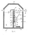
- Fig. 1 to 4 are schematic representations of an embodiment of the biological clarifier according to the invention in different operating conditions.
- Fig. 1 shown biological clarifier which is designated in its entirety by the reference numeral 10, comprises a left in the figures arranged Vorußhunt 12 and a clarifying chamber 14, which are arranged within a cylindrical container 16, which is closed by a cover 18.
- the pre-clearing chamber 12 and the clarification chamber 14 are separated from each other by a partition wall 20.
- a waste water inlet 22 is arranged, through which wastewater is introduced into the pre-treatment chamber 12.
- coarse impurities may settle on the bottom or in the region of the water level before the wastewater is transferred into the actual clarification chamber 14. This transfer can be done for example by arranged in the upper part of the partition wall overflows 20, by pumping devices or the like, which are well known and are not shown in detail for reasons of clarity in the figures.
- a biological wastewater treatment takes place.
- the microorganisms provide for the biological clarification.
- the purified wastewater leaves the clarification chamber 14 via a suitable outlet in the upper region of the clarification chamber 14. Since the activated sludge 23 settles at the bottom of the clarification chamber 14, the clear water can be removed from the surface region of the clarification chamber 14.
- an aerator 24 is arranged in the bottom region of the clarification chamber 14, which is a membrane fan.
- the aerator 24 is supplied via a pressure line 29 with an air-containing pressurized fluid, such as compressed air or an air-water mixture.
- the pressure source is a compressor 26 arranged outside the container 16, which supplies the aerator 24 with compressed air via the pressure line 29.
- a sludge lifter located in the clarification chamber 14 in the region of the partition wall 20, a sludge lifter in the form of a compressed air lift 28 for returning sludge from the bottom region of the clarification chamber 14 back into the pretreatment chamber 12 via the partition 20 away.
- the compressor 26 instead of the compressor 26, to provide a water pump as a pressure source which pumps water under pressure in the direction of the aerator 24 through the pressure line 29.
- a water pump As a pressure source which pumps water under pressure in the direction of the aerator 24 through the pressure line 29.
- an air suction line which is connected via an injector to the pressure line 29, the zugechelte water can be enriched with air.
- the compressed fluid is compressed air.
- this selection is not restrictive.
- the air lift 28 must be supplied to his operation also with compressed air.
- a branch line 30 which opens laterally into the lower region of the compressed air lift 28.
- first section 32 of the pressure line 29 opens into an inlet of a T-piece 34 having two outlets.
- the first of these outlets is connected via a further pressure line section 36 to the aerator 24, while the second outlet via the branch 30 at a pressure port 40 is connected to the compressed air lift 28.
- the compressed air generated by the compressor 26 can be distributed to the aerator 24 and on the compressed air lift 28, as will be described in more detail below.
- the compressed air lifter 28 is substantially a vertical, at its upper end above the partition wall 20 angled tube 38, on the tube wall of the pressure port 40 is arranged.
- the upper portion of this tube 38, which is located above the pressure port 40, will hereinafter be referred to as ascending tube section 42.
- Below the pressure port 40 connects to the lower end of the rising pipe section 42 a much shorter descending pipe section 44 at.
- an upper valve body in the form of a valve ball 46, the diameter of which is slightly smaller than the inner diameter of the rising pipe section 42, so that the upper valve ball 46 is freely movable upwardly and downwardly within this pipe section 42.
- an upper valve seat 48 is attached, which is closed by the upper valve ball 46.
- a pin 50 is inserted laterally into the pipe wall, which serves as a lower stop for the upper valve ball 46.
- the upper valve ball 46 has a density> 1, that is greater than the wastewater in the clarification chamber 14. If the compressed air lifter 28 is filled, the upper valve ball 46 is therefore due to its own weight on the pin 50.
- the water level 52 of the clarification chamber 14 is located in the upper region of the dividing wall 20 far above the pressure port 40, so that the rising Rohrabitest 42 is largely filled with waste water or a mixture of water and sludge.
- the upper valve ball 46 is, as already mentioned, in this case on the pin 50. Is by an operation of the compressor 26 air via the branch 30 in the lower region of the Compressed air lifter 28 is initiated, the upper valve ball 46 is driven upward, and above the upper valve ball 46 located water-mud mixture is conveyed through the upper end of the air lift 28 in the pre-treatment chamber 12 until the upper valve ball 46 reaches the upper valve seat 48 and largely closes it.
- a valve body In the descending pipe section 44 is also a valve body, namely a lower valve ball 54 whose diameter is slightly smaller than the inner diameter of the descending pipe section 44, so that this lower valve ball 54 can move freely up and down in the descending pipe section 44.
- the lower end of this descending pipe section 44 is located at a predetermined distance above the bottom of the clarifying chamber 14 and is formed as a valve seat 56 for the lower valve ball 54, so that the lower valve ball 54 together with its valve seat 56 forms a lower valve, which by a Pressurization of the air lift 28 is closed from the inside.
- the lower valve ball 54 has a density ⁇ 1. that is smaller than the wastewater in the clarification chamber 14, so that the ball 54 floats at filled descending pipe section 44.
- the lower valve ball 54 floats against the pin 50, which serves as an upper stop for the lower valve ball 54.
- the pin 50 thus serves as a common stop for the upper valve ball 46 and the lower valve ball 54th
- the biological clarifier 10 described above operates as follows.
- Fig. 1 shows the situation at the end of a ventilation break, in which the activated sludge 23 has collected in the lower region of the clarification chamber 14. Above the activated sludge 23 is clear water 58 below the water level 52. The water level 52 is slightly below the upper valve seat 48, so that the rising pipe section 42 is largely filled with a water-sludge mixture.
- the system is depressurized here, ie the compressor 26 does not supply the compressed air lift 28 and the aerator 24 with compressed air.
- the upper valve ball 46 rests on the pin 50, while the lower valve ball 54 floats against the pin 50 from below.
- the compressed air entering the compressed-air jack 28 drives the lower valve ball 54 down into the lower valve seat 56 of the descending pipe section 44 and closes it. At this moment, the compressed air lifter 28 is closed at both ends ( Fig. 4 ).
- the closing of the lower valve seat 56 through the lower valve ball 54 may happen depending on the design of the air lift 28 before reaching the upper valve seat 48 through the upper valve ball 46, so that the airlift 28 is first closed at its lower end and the churning off the Subsequently contained therein sludge takes place.
- the compressed air entering the T-piece 34 can then penetrate via the second pressure line section 36 into the aerator 24 and supply it with air. This means that oxygen is introduced into the clarification chamber 14 after initially excess sludge has been discharged into the primary clarification chamber 12.
- the ventilation of the clarification chamber 14 is usually intermittent, ie, ventilation phases alternate with ventilation pauses.
- the activated sludge 23 can collect at the bottom of the clarification chamber 14.
- the above-described surge mud feedback takes place by the compressed air lifter 28, which is followed by the ventilation by the operation of the aerator 24.
- the valve balls 46 and 54 solve This may be at the upper valve seat 48 or at another suitable location a slight leak, through which some air can escape to the outside, so that the upper valve ball 46 again easily from the Valve seat 48 can solve.
- a mud-water mixture can again penetrate through the open lower valve seat 56 from the lower end of the compressed-air lift 28 and fill the compressed air lift 28.
- the amount of activated sludge 23 in the clarification chamber 14 can thus be controlled by the choice of the height of the lower end of the descending pipe section 44 via the bottom of the clarification chamber 14. The smaller the height, the more sludge is carried away in one recycle cycle. Furthermore, of course, the amount of sludge can be controlled by the length of the ventilation and Absetzintervalle.
- the construction according to the invention offers the significant advantage that no complex valves such as solenoid valves or the like as well as control devices are required to control the pressure fluid distribution on the compressed air lift 28 and the aerator 24.
Landscapes
- Life Sciences & Earth Sciences (AREA)
- Engineering & Computer Science (AREA)
- Chemical & Material Sciences (AREA)
- Organic Chemistry (AREA)
- Hydrology & Water Resources (AREA)
- Environmental & Geological Engineering (AREA)
- Water Supply & Treatment (AREA)
- Microbiology (AREA)
- Biodiversity & Conservation Biology (AREA)
- Chemical Kinetics & Catalysis (AREA)
- Physics & Mathematics (AREA)
- Fluid Mechanics (AREA)
- Mechanical Engineering (AREA)
- Aeration Devices For Treatment Of Activated Polluted Sludge (AREA)
- Treatment Of Biological Wastes In General (AREA)
- Measuring Pulse, Heart Rate, Blood Pressure Or Blood Flow (AREA)
Priority Applications (1)
| Application Number | Priority Date | Filing Date | Title |
|---|---|---|---|
| PL09001248T PL2098487T3 (pl) | 2008-03-04 | 2009-01-29 | Biologiczna oczyszczalnia ścieków |
Applications Claiming Priority (1)
| Application Number | Priority Date | Filing Date | Title |
|---|---|---|---|
| DE200820003062 DE202008003062U1 (de) | 2008-03-04 | 2008-03-04 | Biologische Klärvorrichtung |
Publications (2)
| Publication Number | Publication Date |
|---|---|
| EP2098487A1 EP2098487A1 (de) | 2009-09-09 |
| EP2098487B1 true EP2098487B1 (de) | 2012-03-21 |
Family
ID=40749108
Family Applications (1)
| Application Number | Title | Priority Date | Filing Date |
|---|---|---|---|
| EP20090001248 Not-in-force EP2098487B1 (de) | 2008-03-04 | 2009-01-29 | Biologische Klärvorrichtung |
Country Status (4)
| Country | Link |
|---|---|
| EP (1) | EP2098487B1 (pl) |
| AT (1) | ATE550302T1 (pl) |
| DE (1) | DE202008003062U1 (pl) |
| PL (1) | PL2098487T3 (pl) |
Cited By (1)
| Publication number | Priority date | Publication date | Assignee | Title |
|---|---|---|---|---|
| AU2018253465B2 (en) * | 2017-10-18 | 2020-01-02 | Hohai University | Automatic draining device for condensed water or leaking water in aeration pipeline |
Families Citing this family (6)
| Publication number | Priority date | Publication date | Assignee | Title |
|---|---|---|---|---|
| DE202010009084U1 (de) * | 2010-06-15 | 2011-11-14 | Atb Umwelttechnologien Gmbh | Biologische Klärvorrichtung |
| CN102032444B (zh) * | 2010-10-22 | 2013-02-20 | 中国人民大学 | 一种凝污水的动态排放装置 |
| CN102001768B (zh) * | 2010-11-17 | 2013-03-20 | 上海同济建设科技有限公司 | 一体化低能耗污水处理装置及其处理方法 |
| DE202011050470U1 (de) | 2011-06-17 | 2012-09-20 | Atb Umwelttechnologien Gmbh | Biologische Klärvorrichtung |
| ES2524162T3 (es) | 2011-06-17 | 2014-12-04 | Atb Umwelttechnologien Gmbh | Dispositivo de depuración biológica |
| DE202016103262U1 (de) * | 2016-06-21 | 2017-09-22 | Atb Umwelttechnologien Gmbh | Abwasserbehandlungsvorrichtung für eine Kläranlage |
Family Cites Families (11)
| Publication number | Priority date | Publication date | Assignee | Title |
|---|---|---|---|---|
| DE1658089A1 (de) * | 1967-04-29 | 1970-06-11 | Menzel & Co | Vorrichtung zum Klaeren von Abwaessern |
| DE1935477C3 (de) * | 1969-07-12 | 1975-03-06 | Deutsche-Abwasser-Reinigungs-Gesellschaft Mbh, Oms Staedtereinigung, 6200 Wiesbaden | Vorrichtung zur biologischen Reinigung von Abwasser |
| DE2144808A1 (de) * | 1971-09-08 | 1973-03-15 | Abwasser Reinigungs Gmbh Oms S | Vorrichtung zur biologischen abwasserreinigung nach dem belebtschlammverfahren |
| AT2014U1 (de) * | 1997-04-14 | 1998-03-25 | Aratec Planungs Und Vertriebsg | Biologische kläranlage und verfahren zum betreiben einer solchen |
| DE59810619D1 (de) * | 1997-07-17 | 2004-02-26 | J H & Wilhelm Finger Gmbh & Co | Verfahren und Vorrichtung zur biologischen Behandlung von Flüssigkeiten, insbesondere zur vollbiologischen Klärung von Abwasser |
| DE20005909U1 (de) * | 2000-03-30 | 2001-08-09 | Boller, Reinhard, Dipl.-Ing., 57234 Wilnsdorf | Kläranlage zur Reinigung von Abwasser |
| DE20204232U1 (de) * | 2002-03-16 | 2002-05-29 | Baumann, Markus, 32602 Vlotho | Klärvorrichtung |
| EP1559686B1 (de) | 2004-01-14 | 2013-03-27 | ATB Umwelttechnologien GmbH | Klärbecken mit Auslasseinrichtung für Klarwasser |
| EP1591424B1 (de) | 2004-04-29 | 2011-06-22 | Markus Baumann | Biologische Klärvorrichtung |
| DE102005034540B4 (de) * | 2005-07-23 | 2009-10-01 | Jung Pumpen Gmbh | Kleinkläranlage und Verfahren zum Betreiben derselben |
| DE102006024717B4 (de) * | 2006-05-26 | 2018-02-08 | Klaro Gmbh | Verfahren zum Betrieb eines Drucklufthebersystems für eine Kleinkläranlage und Drucklufthebersystem |
-
2008
- 2008-03-04 DE DE200820003062 patent/DE202008003062U1/de not_active Expired - Lifetime
-
2009
- 2009-01-29 EP EP20090001248 patent/EP2098487B1/de not_active Not-in-force
- 2009-01-29 PL PL09001248T patent/PL2098487T3/pl unknown
- 2009-01-29 AT AT09001248T patent/ATE550302T1/de active
Cited By (1)
| Publication number | Priority date | Publication date | Assignee | Title |
|---|---|---|---|---|
| AU2018253465B2 (en) * | 2017-10-18 | 2020-01-02 | Hohai University | Automatic draining device for condensed water or leaking water in aeration pipeline |
Also Published As
| Publication number | Publication date |
|---|---|
| PL2098487T3 (pl) | 2012-07-31 |
| EP2098487A1 (de) | 2009-09-09 |
| DE202008003062U1 (de) | 2009-08-06 |
| ATE550302T1 (de) | 2012-04-15 |
Similar Documents
| Publication | Publication Date | Title |
|---|---|---|
| EP2641876B1 (de) | Biologische Klärvorrichtung | |
| EP2098487B1 (de) | Biologische Klärvorrichtung | |
| DE102011122695B4 (de) | Klarwasser- Druckluftheber für biologische Kläranlagen und Verfahren zu dessen Betrieb | |
| DE102010049709B3 (de) | Klarwasser-Druckluftheber für biologische Kläranlagen, Verfahren zu dessen Betrieb und dessen Verwendung | |
| DE1784338A1 (de) | Schlamm-Klaeranlage | |
| DE102014015488B4 (de) | Zweifunktionaler Druckluftheber für biologische Kläranlagen, Verfahren zu dessen Betrieb und dessen Verwendung | |
| EP2743515A2 (de) | Wasserhebevorrichtung für gereinigtes Wasser aus einem Reinigungsbecken | |
| DE1461395A1 (de) | Steuereinrichtung fuer die Fluessigkeitsstroeme in einer Filteranlage | |
| DE202009014465U1 (de) | Vorrichtung in Form eines Drucklufthebers | |
| EP2535317B1 (de) | Biologische Klärvorrichtung | |
| DE202015105725U1 (de) | Dreifunktionaler Druckluftheber für biologische Kläranlagen | |
| BE1018933A4 (de) | Vorrichtung zum entfernen von organischen bestandteilen aus dem wasser von aquarien. | |
| EP1582263A1 (de) | Drucklufthebeanlage für fliessfähige Medien | |
| AT392062B (de) | Verfahren zum eindicken von abwasserschlaemmen und/oder anderen organischen schlaemmen sowie einrichtung zur durchfuehrung dieses verfahrens | |
| DE202008009513U1 (de) | Vorrichtung in Form eines Festbettkörpers | |
| DE102016117462B3 (de) | Druckluftklarwasserheber mit Verunreinigungsschutz | |
| DE102016102730B3 (de) | Druckluftheber als höhenverstellbarer Klarwasserheber mit einer aktiven Rückspülfunktion, Verfahren zu dessen Betrieb in Behältern von biologischen Kläranlagen und dessen Verwendung | |
| DE10203076C1 (de) | Vorrichtung zur Behandlung einer Flüssigkeit sowie Verfahren zum steuerbaren Überleiten einer Flüssigkeit | |
| EP1493717A1 (de) | Verfahren zum Spülen eines Reaktors zur biologischen Abwasserreinigung | |
| DE202010009084U1 (de) | Biologische Klärvorrichtung | |
| DE202016100805U1 (de) | Druckluftheber als höhenverstellbarer Klarwasserheber mit einer aktiven Rückspülfunktion | |
| EP1588987B1 (de) | Kläranlage mit konzentrisch angeordneten Becken | |
| EP0258525B1 (de) | Vakuum-Entwässerungsanlage | |
| EP1300367A2 (de) | Kleinkläranlage zur Behandlung von Abwasser | |
| DE102006010569A1 (de) | Unterdruckabwassereinrichtung |
Legal Events
| Date | Code | Title | Description |
|---|---|---|---|
| PUAI | Public reference made under article 153(3) epc to a published international application that has entered the european phase |
Free format text: ORIGINAL CODE: 0009012 |
|
| AK | Designated contracting states |
Kind code of ref document: A1 Designated state(s): AT BE BG CH CY CZ DE DK EE ES FI FR GB GR HR HU IE IS IT LI LT LU LV MC MK MT NL NO PL PT RO SE SI SK TR |
|
| AX | Request for extension of the european patent |
Extension state: AL BA RS |
|
| RIN1 | Information on inventor provided before grant (corrected) |
Inventor name: BAUMANN, MARKUS Inventor name: VOGT, TORSTEN |
|
| 17P | Request for examination filed |
Effective date: 20091112 |
|
| AKX | Designation fees paid |
Designated state(s): AT BE BG CH CY CZ DE DK EE ES FI FR GB GR HR HU IE IS IT LI LT LU LV MC MK MT NL NO PL PT RO SE SI SK TR |
|
| 17Q | First examination report despatched |
Effective date: 20101028 |
|
| GRAP | Despatch of communication of intention to grant a patent |
Free format text: ORIGINAL CODE: EPIDOSNIGR1 |
|
| RIC1 | Information provided on ipc code assigned before grant |
Ipc: C02F 3/12 20060101AFI20110725BHEP Ipc: C02F 1/00 20060101ALN20110725BHEP Ipc: B01D 21/24 20060101ALI20110725BHEP Ipc: C02F 3/20 20060101ALI20110725BHEP Ipc: B08B 9/055 20060101ALI20110725BHEP |
|
| GRAS | Grant fee paid |
Free format text: ORIGINAL CODE: EPIDOSNIGR3 |
|
| GRAA | (expected) grant |
Free format text: ORIGINAL CODE: 0009210 |
|
| AK | Designated contracting states |
Kind code of ref document: B1 Designated state(s): AT BE BG CH CY CZ DE DK EE ES FI FR GB GR HR HU IE IS IT LI LT LU LV MC MK MT NL NO PL PT RO SE SI SK TR |
|
| REG | Reference to a national code |
Ref country code: GB Ref legal event code: FG4D Free format text: NOT ENGLISH |
|
| REG | Reference to a national code |
Ref country code: CH Ref legal event code: EP |
|
| REG | Reference to a national code |
Ref country code: IE Ref legal event code: FG4D Free format text: LANGUAGE OF EP DOCUMENT: GERMAN |
|
| REG | Reference to a national code |
Ref country code: AT Ref legal event code: REF Ref document number: 550302 Country of ref document: AT Kind code of ref document: T Effective date: 20120415 |
|
| REG | Reference to a national code |
Ref country code: DE Ref legal event code: R096 Ref document number: 502009003048 Country of ref document: DE Effective date: 20120516 |
|
| REG | Reference to a national code |
Ref country code: NL Ref legal event code: VDEP Effective date: 20120321 |
|
| PG25 | Lapsed in a contracting state [announced via postgrant information from national office to epo] |
Ref country code: HR Free format text: LAPSE BECAUSE OF FAILURE TO SUBMIT A TRANSLATION OF THE DESCRIPTION OR TO PAY THE FEE WITHIN THE PRESCRIBED TIME-LIMIT Effective date: 20120321 Ref country code: NO Free format text: LAPSE BECAUSE OF FAILURE TO SUBMIT A TRANSLATION OF THE DESCRIPTION OR TO PAY THE FEE WITHIN THE PRESCRIBED TIME-LIMIT Effective date: 20120621 Ref country code: LT Free format text: LAPSE BECAUSE OF FAILURE TO SUBMIT A TRANSLATION OF THE DESCRIPTION OR TO PAY THE FEE WITHIN THE PRESCRIBED TIME-LIMIT Effective date: 20120321 |
|
| REG | Reference to a national code |
Ref country code: PL Ref legal event code: T3 |
|
| LTIE | Lt: invalidation of european patent or patent extension |
Effective date: 20120321 |
|
| PG25 | Lapsed in a contracting state [announced via postgrant information from national office to epo] |
Ref country code: FI Free format text: LAPSE BECAUSE OF FAILURE TO SUBMIT A TRANSLATION OF THE DESCRIPTION OR TO PAY THE FEE WITHIN THE PRESCRIBED TIME-LIMIT Effective date: 20120321 Ref country code: GR Free format text: LAPSE BECAUSE OF FAILURE TO SUBMIT A TRANSLATION OF THE DESCRIPTION OR TO PAY THE FEE WITHIN THE PRESCRIBED TIME-LIMIT Effective date: 20120622 Ref country code: LV Free format text: LAPSE BECAUSE OF FAILURE TO SUBMIT A TRANSLATION OF THE DESCRIPTION OR TO PAY THE FEE WITHIN THE PRESCRIBED TIME-LIMIT Effective date: 20120321 |
|
| PG25 | Lapsed in a contracting state [announced via postgrant information from national office to epo] |
Ref country code: CY Free format text: LAPSE BECAUSE OF FAILURE TO SUBMIT A TRANSLATION OF THE DESCRIPTION OR TO PAY THE FEE WITHIN THE PRESCRIBED TIME-LIMIT Effective date: 20120321 |
|
| PG25 | Lapsed in a contracting state [announced via postgrant information from national office to epo] |
Ref country code: CZ Free format text: LAPSE BECAUSE OF FAILURE TO SUBMIT A TRANSLATION OF THE DESCRIPTION OR TO PAY THE FEE WITHIN THE PRESCRIBED TIME-LIMIT Effective date: 20120321 Ref country code: SE Free format text: LAPSE BECAUSE OF FAILURE TO SUBMIT A TRANSLATION OF THE DESCRIPTION OR TO PAY THE FEE WITHIN THE PRESCRIBED TIME-LIMIT Effective date: 20120321 Ref country code: EE Free format text: LAPSE BECAUSE OF FAILURE TO SUBMIT A TRANSLATION OF THE DESCRIPTION OR TO PAY THE FEE WITHIN THE PRESCRIBED TIME-LIMIT Effective date: 20120321 Ref country code: SI Free format text: LAPSE BECAUSE OF FAILURE TO SUBMIT A TRANSLATION OF THE DESCRIPTION OR TO PAY THE FEE WITHIN THE PRESCRIBED TIME-LIMIT Effective date: 20120321 Ref country code: IS Free format text: LAPSE BECAUSE OF FAILURE TO SUBMIT A TRANSLATION OF THE DESCRIPTION OR TO PAY THE FEE WITHIN THE PRESCRIBED TIME-LIMIT Effective date: 20120721 Ref country code: RO Free format text: LAPSE BECAUSE OF FAILURE TO SUBMIT A TRANSLATION OF THE DESCRIPTION OR TO PAY THE FEE WITHIN THE PRESCRIBED TIME-LIMIT Effective date: 20120321 |
|
| PG25 | Lapsed in a contracting state [announced via postgrant information from national office to epo] |
Ref country code: PT Free format text: LAPSE BECAUSE OF FAILURE TO SUBMIT A TRANSLATION OF THE DESCRIPTION OR TO PAY THE FEE WITHIN THE PRESCRIBED TIME-LIMIT Effective date: 20120723 Ref country code: SK Free format text: LAPSE BECAUSE OF FAILURE TO SUBMIT A TRANSLATION OF THE DESCRIPTION OR TO PAY THE FEE WITHIN THE PRESCRIBED TIME-LIMIT Effective date: 20120321 |
|
| PLBE | No opposition filed within time limit |
Free format text: ORIGINAL CODE: 0009261 |
|
| STAA | Information on the status of an ep patent application or granted ep patent |
Free format text: STATUS: NO OPPOSITION FILED WITHIN TIME LIMIT |
|
| PG25 | Lapsed in a contracting state [announced via postgrant information from national office to epo] |
Ref country code: DK Free format text: LAPSE BECAUSE OF FAILURE TO SUBMIT A TRANSLATION OF THE DESCRIPTION OR TO PAY THE FEE WITHIN THE PRESCRIBED TIME-LIMIT Effective date: 20120321 Ref country code: NL Free format text: LAPSE BECAUSE OF FAILURE TO SUBMIT A TRANSLATION OF THE DESCRIPTION OR TO PAY THE FEE WITHIN THE PRESCRIBED TIME-LIMIT Effective date: 20120321 |
|
| 26N | No opposition filed |
Effective date: 20130102 |
|
| PG25 | Lapsed in a contracting state [announced via postgrant information from national office to epo] |
Ref country code: IT Free format text: LAPSE BECAUSE OF FAILURE TO SUBMIT A TRANSLATION OF THE DESCRIPTION OR TO PAY THE FEE WITHIN THE PRESCRIBED TIME-LIMIT Effective date: 20120321 |
|
| REG | Reference to a national code |
Ref country code: DE Ref legal event code: R097 Ref document number: 502009003048 Country of ref document: DE Effective date: 20130102 |
|
| PG25 | Lapsed in a contracting state [announced via postgrant information from national office to epo] |
Ref country code: ES Free format text: LAPSE BECAUSE OF FAILURE TO SUBMIT A TRANSLATION OF THE DESCRIPTION OR TO PAY THE FEE WITHIN THE PRESCRIBED TIME-LIMIT Effective date: 20120702 |
|
| PG25 | Lapsed in a contracting state [announced via postgrant information from national office to epo] |
Ref country code: BG Free format text: LAPSE BECAUSE OF FAILURE TO SUBMIT A TRANSLATION OF THE DESCRIPTION OR TO PAY THE FEE WITHIN THE PRESCRIBED TIME-LIMIT Effective date: 20120621 |
|
| PG25 | Lapsed in a contracting state [announced via postgrant information from national office to epo] |
Ref country code: MC Free format text: LAPSE BECAUSE OF NON-PAYMENT OF DUE FEES Effective date: 20130131 |
|
| REG | Reference to a national code |
Ref country code: CH Ref legal event code: PL |
|
| PG25 | Lapsed in a contracting state [announced via postgrant information from national office to epo] |
Ref country code: CH Free format text: LAPSE BECAUSE OF NON-PAYMENT OF DUE FEES Effective date: 20130131 Ref country code: LI Free format text: LAPSE BECAUSE OF NON-PAYMENT OF DUE FEES Effective date: 20130131 |
|
| PG25 | Lapsed in a contracting state [announced via postgrant information from national office to epo] |
Ref country code: MT Free format text: LAPSE BECAUSE OF FAILURE TO SUBMIT A TRANSLATION OF THE DESCRIPTION OR TO PAY THE FEE WITHIN THE PRESCRIBED TIME-LIMIT Effective date: 20120321 |
|
| REG | Reference to a national code |
Ref country code: AT Ref legal event code: MM01 Ref document number: 550302 Country of ref document: AT Kind code of ref document: T Effective date: 20140129 |
|
| PG25 | Lapsed in a contracting state [announced via postgrant information from national office to epo] |
Ref country code: AT Free format text: LAPSE BECAUSE OF NON-PAYMENT OF DUE FEES Effective date: 20140129 |
|
| PG25 | Lapsed in a contracting state [announced via postgrant information from national office to epo] |
Ref country code: TR Free format text: LAPSE BECAUSE OF FAILURE TO SUBMIT A TRANSLATION OF THE DESCRIPTION OR TO PAY THE FEE WITHIN THE PRESCRIBED TIME-LIMIT Effective date: 20120321 |
|
| PG25 | Lapsed in a contracting state [announced via postgrant information from national office to epo] |
Ref country code: LU Free format text: LAPSE BECAUSE OF NON-PAYMENT OF DUE FEES Effective date: 20130129 Ref country code: MK Free format text: LAPSE BECAUSE OF FAILURE TO SUBMIT A TRANSLATION OF THE DESCRIPTION OR TO PAY THE FEE WITHIN THE PRESCRIBED TIME-LIMIT Effective date: 20120321 Ref country code: HU Free format text: LAPSE BECAUSE OF FAILURE TO SUBMIT A TRANSLATION OF THE DESCRIPTION OR TO PAY THE FEE WITHIN THE PRESCRIBED TIME-LIMIT; INVALID AB INITIO Effective date: 20090129 |
|
| REG | Reference to a national code |
Ref country code: FR Ref legal event code: PLFP Year of fee payment: 8 |
|
| REG | Reference to a national code |
Ref country code: FR Ref legal event code: PLFP Year of fee payment: 9 |
|
| REG | Reference to a national code |
Ref country code: FR Ref legal event code: PLFP Year of fee payment: 10 |
|
| PGFP | Annual fee paid to national office [announced via postgrant information from national office to epo] |
Ref country code: GB Payment date: 20180125 Year of fee payment: 10 Ref country code: DE Payment date: 20180130 Year of fee payment: 10 |
|
| PGFP | Annual fee paid to national office [announced via postgrant information from national office to epo] |
Ref country code: PL Payment date: 20180117 Year of fee payment: 10 Ref country code: BE Payment date: 20180124 Year of fee payment: 10 Ref country code: FR Payment date: 20180124 Year of fee payment: 10 Ref country code: IE Payment date: 20180125 Year of fee payment: 10 |
|
| REG | Reference to a national code |
Ref country code: DE Ref legal event code: R119 Ref document number: 502009003048 Country of ref document: DE |
|
| GBPC | Gb: european patent ceased through non-payment of renewal fee |
Effective date: 20190129 |
|
| REG | Reference to a national code |
Ref country code: BE Ref legal event code: MM Effective date: 20190131 |
|
| REG | Reference to a national code |
Ref country code: IE Ref legal event code: MM4A |
|
| PG25 | Lapsed in a contracting state [announced via postgrant information from national office to epo] |
Ref country code: DE Free format text: LAPSE BECAUSE OF NON-PAYMENT OF DUE FEES Effective date: 20190801 Ref country code: FR Free format text: LAPSE BECAUSE OF NON-PAYMENT OF DUE FEES Effective date: 20190131 |
|
| PG25 | Lapsed in a contracting state [announced via postgrant information from national office to epo] |
Ref country code: BE Free format text: LAPSE BECAUSE OF NON-PAYMENT OF DUE FEES Effective date: 20190131 |
|
| PG25 | Lapsed in a contracting state [announced via postgrant information from national office to epo] |
Ref country code: GB Free format text: LAPSE BECAUSE OF NON-PAYMENT OF DUE FEES Effective date: 20190129 |
|
| PG25 | Lapsed in a contracting state [announced via postgrant information from national office to epo] |
Ref country code: IE Free format text: LAPSE BECAUSE OF NON-PAYMENT OF DUE FEES Effective date: 20190129 |
|
| PG25 | Lapsed in a contracting state [announced via postgrant information from national office to epo] |
Ref country code: PL Free format text: LAPSE BECAUSE OF NON-PAYMENT OF DUE FEES Effective date: 20190129 |