EP2098326A2 - Verfahren zur Herstellung eines metallischen Bauteils - Google Patents
Verfahren zur Herstellung eines metallischen Bauteils Download PDFInfo
- Publication number
- EP2098326A2 EP2098326A2 EP08012008A EP08012008A EP2098326A2 EP 2098326 A2 EP2098326 A2 EP 2098326A2 EP 08012008 A EP08012008 A EP 08012008A EP 08012008 A EP08012008 A EP 08012008A EP 2098326 A2 EP2098326 A2 EP 2098326A2
- Authority
- EP
- European Patent Office
- Prior art keywords
- coating
- metallic component
- steel
- tool
- metallic
- Prior art date
- Legal status (The legal status is an assumption and is not a legal conclusion. Google has not performed a legal analysis and makes no representation as to the accuracy of the status listed.)
- Granted
Links
Images
Classifications
-
- B—PERFORMING OPERATIONS; TRANSPORTING
- B23—MACHINE TOOLS; METAL-WORKING NOT OTHERWISE PROVIDED FOR
- B23K—SOLDERING OR UNSOLDERING; WELDING; CLADDING OR PLATING BY SOLDERING OR WELDING; CUTTING BY APPLYING HEAT LOCALLY, e.g. FLAME CUTTING; WORKING BY LASER BEAM
- B23K20/00—Non-electric welding by applying impact or other pressure, with or without the application of heat, e.g. cladding or plating
- B23K20/12—Non-electric welding by applying impact or other pressure, with or without the application of heat, e.g. cladding or plating the heat being generated by friction; Friction welding
- B23K20/1215—Non-electric welding by applying impact or other pressure, with or without the application of heat, e.g. cladding or plating the heat being generated by friction; Friction welding for other purposes than joining, e.g. built-up welding
-
- B—PERFORMING OPERATIONS; TRANSPORTING
- B23—MACHINE TOOLS; METAL-WORKING NOT OTHERWISE PROVIDED FOR
- B23K—SOLDERING OR UNSOLDERING; WELDING; CLADDING OR PLATING BY SOLDERING OR WELDING; CUTTING BY APPLYING HEAT LOCALLY, e.g. FLAME CUTTING; WORKING BY LASER BEAM
- B23K20/00—Non-electric welding by applying impact or other pressure, with or without the application of heat, e.g. cladding or plating
- B23K20/22—Non-electric welding by applying impact or other pressure, with or without the application of heat, e.g. cladding or plating taking account of the properties of the materials to be welded
- B23K20/227—Non-electric welding by applying impact or other pressure, with or without the application of heat, e.g. cladding or plating taking account of the properties of the materials to be welded with ferrous layer
-
- B—PERFORMING OPERATIONS; TRANSPORTING
- B23—MACHINE TOOLS; METAL-WORKING NOT OTHERWISE PROVIDED FOR
- B23K—SOLDERING OR UNSOLDERING; WELDING; CLADDING OR PLATING BY SOLDERING OR WELDING; CUTTING BY APPLYING HEAT LOCALLY, e.g. FLAME CUTTING; WORKING BY LASER BEAM
- B23K2101/00—Articles made by soldering, welding or cutting
- B23K2101/006—Vehicles
-
- B—PERFORMING OPERATIONS; TRANSPORTING
- B23—MACHINE TOOLS; METAL-WORKING NOT OTHERWISE PROVIDED FOR
- B23K—SOLDERING OR UNSOLDERING; WELDING; CLADDING OR PLATING BY SOLDERING OR WELDING; CUTTING BY APPLYING HEAT LOCALLY, e.g. FLAME CUTTING; WORKING BY LASER BEAM
- B23K2103/00—Materials to be soldered, welded or cut
- B23K2103/02—Iron or ferrous alloys
- B23K2103/04—Steel or steel alloys
-
- B—PERFORMING OPERATIONS; TRANSPORTING
- B23—MACHINE TOOLS; METAL-WORKING NOT OTHERWISE PROVIDED FOR
- B23K—SOLDERING OR UNSOLDERING; WELDING; CLADDING OR PLATING BY SOLDERING OR WELDING; CUTTING BY APPLYING HEAT LOCALLY, e.g. FLAME CUTTING; WORKING BY LASER BEAM
- B23K2103/00—Materials to be soldered, welded or cut
- B23K2103/02—Iron or ferrous alloys
- B23K2103/06—Cast-iron alloys
-
- B—PERFORMING OPERATIONS; TRANSPORTING
- B23—MACHINE TOOLS; METAL-WORKING NOT OTHERWISE PROVIDED FOR
- B23K—SOLDERING OR UNSOLDERING; WELDING; CLADDING OR PLATING BY SOLDERING OR WELDING; CUTTING BY APPLYING HEAT LOCALLY, e.g. FLAME CUTTING; WORKING BY LASER BEAM
- B23K2103/00—Materials to be soldered, welded or cut
- B23K2103/18—Dissimilar materials
Definitions
- the present invention relates to a method for producing a metallic component, in particular a tool, according to the preamble of claim 1, a metallic component, in particular tool, according to the preamble of claim 8 and a use of such a component.
- Metallically highly stressed components such as tools
- Such forming tools usually have a base material or body made of cast iron or steel. Due to the wear occurring over the service life and / or for adaptation often replacement or editing of the tools or components - namely a Neuherstellen, changing, repairing, coating or the like, in the present invention simply called "manufacturing" - required.
- the base material or basic body of the tool which can be made of ductile iron, for example GJS, is changed by the heat introduced in the welding process in the structure and in its properties.
- GJS ductile iron
- large tools whose dimensions are often in the meter range must therefore be additionally preheated.
- corresponding welding consumables for a buffer and functional layer necessary to ensure a long-term adherent connection to the base material and a wear-resistant surface.
- the US Pat. No. 7,225,969 B2 relates to a plastic surface treatment of a workpiece, wherein a rotating tool is pressed onto the rotating tool surface.
- the present invention has for its object to provide a method for producing a metallic component, in particular a tool, a metallic component, in particular a tool, and a use of such a component, wherein the manufacturing or processing costs can be reduced, wherein a Buffer layer between the coating and the base material can be dispensed with, new combinations of materials are possible and / or wherein the thermal load of the base material can be minimized.
- the basic idea of the present invention is to apply a coating of a second metallic material to a base material or to a base body made of a first metallic material by friction-deposition welding, the second material being harder and / or more wear-resistant than the first material.
- the present invention provides for a wear-resistant material (the second material) to be applied to the base material via a hot-forming process (friction-welding) in one step.
- the necessary material properties (deformable) of the second material are actually in contradiction to the use properties (more resistant to wear and / or harder than the first material or the main body) to be.
- initial tests have shown that the proposed coating with the second material leads to very good tool properties with little effort.
- the proposed solution reduces the heat input and thus also the distortion and residual stresses in the component, there is only a small heat flow zone, a preheating of the component can be omitted.
- the degree of mixing of the base material is minimal. Burning of alloying elements of the coating material is minimized or avoided.
- the proposed solution allows a refinement of the structure of the coating material with the result of improved mechanical properties, in particular improved wear resistance.
- the proposed solution provides a quasi-purely mechanical process, whereby a particularly good reproducibility and process stability is relatively easy to achieve.
- the friction coating welding can be performed in a machine tool for milling and / or grinding. Accordingly, already simplifies the previous process sequence in the subsequent application or renewal of the coating, as described above, significantly.
- both the material application by friction welding and the pre-and post-processing grinding, milling
- both the material application by friction welding and the pre-and post-processing can be done, since only mechanical processes are used. In particular, the components or tools no longer have to be moved and re-clamped. Rather, the entire machining process can be done in one machine.
- the proposed solution can also be implemented directly on the built-in component or tool, which further reduces the effort, since in particular a removal and replacement of the component or tool are not required.
- the need to support the large reaction forces by corresponding stable mechanical systems for large tools is not a problem, since these tools are already sufficiently mechanically supported anyway.
- the proposed solution allows an extension of the service life, especially in sheet metal forming tools.
- the proposed solution allows a flexible adaptation of tools, especially particularly flexible wear repairs.
- the proposed solution allows the reduction of side and dead times in the production process, especially taking into account necessary repairs, changes u. Like. Over the life cycle of a tool.
- the proposed solution allows the connection of non "melt-weldable” materials or new material combinations.
- the proposed solution allows the use of alternative tool materials for heavily loaded areas, which can not be realized with other methods (primarily Schmetz welding) in combination with nodular cast iron or GJS. This allows a significant increase in service life.
- high-hardness mold materials for the coating. Such materials can not melt fusion technology or connect only with great difficulty with a cast base material.
- the proposed solution affects the base material significantly lower. Therefore, no consequential damage in the structure is to be feared. In particular, in the proposed solution otherwise required intermediate steps, such as intermediate annealing omitted.
- the proposed solution allows a significant reduction in the production time and / or more flexible adaptation in the inlet and in the repair of components or tools.
- the term "manufacturing” not only a new production, but in particular or possibly only a repair, correction, change o. The like., As required in particular for tools in the break-in phase and / or used tools to understand.
- the present invention relates to a metallic component 1 and to a method for producing the component 1 and its use.
- the component 1 is designed in particular as a tool, particularly preferably as a forming tool.
- the component 1 can also be any other component or component, in particular in or for the automotive sector or construction.
- the component 1 has a base material or base body 2 made of a first material, in particular cast iron, particularly preferably nodular cast iron.
- the ductile iron is preferably GJS, in particular GJS700-2 or the like, or preferably GGG, in particular GG70L or the like.
- the component 1 further comprises or is provided with a coating 3 made of a second material.
- the second material or the coating 3 is harder and / or more wear-resistant than the first material or the base material / base body 2.
- the second material or coating material is preferably steel, in particular a martensitaushärtender steel used.
- a second material or coating material in particular a hot-work steel or cold work steel is used.
- a Ni-based material and / or powder may also be used as the second material.
- a particle-reinforced material can also be used.
- the coating 3 or the second material is applied to the first material or the main body 2 by friction-welding, in particular directly or without buffer layer and / or in a single step.
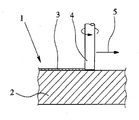
- a rotating element 4 made of the second material is preferably pressed axially onto the first material and preferably moved transversely or laterally, in particular parallel to the surface of the base body 2, as indicated by the arrow 5.
- the coating 2 is formed as proposed.
- the generated frictional heat leads to a plasticization of the second material, in particular without (relevant) melting of the first material in the region of the contact zone.
- the heat input can in particular by suitable choice of the main parameters (speed and axial force and diameter and / or shape of the element 4 - for example, bolt-shaped, pin-shaped, cylindrical, conical, annular, hollow cylindrical o. The like.) Are set.
- the thickness of the coating 3 can be influenced and in particular determined by this and / or by the lateral feed rate.
- the compound of the resulting coating 3 with the substrate (base body 2) takes place in particular by a combination of mechanical and chemical gearing.
- the present invention provides, in particular, for the coating 3 to be applied in one step-very particularly preferably without the production of a buffer layer, adhesion-promoted layer or the like between the base body 2 and the coating 3.
- the coating 3 may be formed in multiple layers, in particular by at least twice proposed Proposal coating by friction surfacing.
- the usual cold and hot working tooling materials can already be transformed today, but this does not take into account adhesion to a base material. These materials can be applied according to the proposal in a simple manner, especially directly on greeting or nodular cast iron.
- the proposed components 1 are in particular as tools for sheet metal processing (forming, stamping, embossing, drawing or edging tools) formed or used and particularly preferably used in the automotive industry, but in principle in other areas.
Landscapes
- Engineering & Computer Science (AREA)
- Mechanical Engineering (AREA)
- Pressure Welding/Diffusion-Bonding (AREA)
Abstract
Description
- Die vorliegende Erfindung betrifft ein Verfahren zur Herstellung eines metallischen Bauteils, insbesondere eines Werkzeugs, gemäß dem Oberbegriff des Anspruchs 1, ein metallisches Bauteil, insbesondere Werkzeug, gemäß dem Oberbegriff des Anspruchs 8 sowie eine Verwendung eines derartigen Bauteils.
- Metallisch hoch beanspruchte Bauteile, wie Werkzeuge, werden für verschiedene Zwecke eingesetzt, insbesondere als Umformwerkzeuge bei der Blechbearbeitung in der Automobilindustrie, Derartige Umformwerkzeuge weisen üblicherweise einen Grundwerkstoff oder Grundkörper aus Guß oder Stahl auf. Aufgrund des über die Lebensdauer auftretenden Verschleißes und/oder zur Anpassung ist oftmals wiederholt ein Austausch oder Bearbeiten der Werkzeuge bzw. Bauteile - nämlich ein Neuherstellen, Ändern, Reparieren, Beschichten oder dergleichen, bei der vorliegenden Erfindung einfach "Herstellen" genannt - erforderlich.
- Derzeit sind zum Herstellen einer Beschichtung bzw. zum Reparieren und Aufbringen von Schichten, Zusatzwerkstoffen, Auftragungen etc. bei einem solchen Werkzeug insbesondere folgende Schritte erforderlich: Ausbau des Werkzeugs, Transport zum Fräsen, Aufspannen und Einrichten, Fräsen, Abspanen, Transport zum Schweißen, Auftragsschweißen (z. T. mit Vorwärmung und Schweißung einer Pufferlage), Transport zum Schleifen, Aufspannen und Einrichten, Schleifen, Abspanen, Transport zur Fertigungslinie sowie Einbau. Diese Schritte führen neben den eigentlichen Fertigungszeiten beim Fräsen, Auftragschweißen und Schleifen zu teilweise erheblichen Neben- und Totzeiten.
- Darüber hinaus wird der Grundwerkstoff bzw. Grundkörper des Werkzeugs, der aus Sphäroguß, beispielsweise GJS, gefertigt sein kann, durch die beim Schweißprozeß eingebrachte Wärme im Gefüge und in seinen Eigenschaften verändert. Um Risse oder zu hohe Eigenspannungen zu vermeiden, müssen große Werkzeuge, deren Abmessungen oft im Meterbereich liegen, daher zusätzlich vorgewärmt werden. Des weiteren sind entsprechende Schweißzusatzwerkstoffe für eine Puffer- und Funktionsschicht notwendig, um eine langfristig festhaftende Verbindung zum Grundwerkstoff und eine verschleißbeständige Oberfläche zu gewährleisten.
- Alternative Lösungen wie CVD- oder PVD-Beschichtungen auf Stahl sind technisch zwar möglich, werden jedoch nur begrenzt eingesetzt. Der Grund liegt in der Notwendigkeit, variable Korrekturen während der Produktionslaufzeit durchführen zu können, was mit CVD- oder PVD-Dünnschichten nicht möglich ist. Nur durch die hohe Variationsmöglichkeit von Korrekturen wird eine gewünschte Optimierung zwischen kostengünstigen und bearbeitbaren Werkstoffen und dem Ausreizen von werkstoffseitigen Grenzbereichen bzw. werkstoffseitiger Grenzbelastung, Verschleiß sowie einer möglichst kostengünstigen Herstellung / Bearbeitbarkeit ermöglicht.
- Aus der
DE 100 18 822 A2 ist es bekannt, zwei Teile eines Werkzeugs durch Reibschweißen miteinander zu verbinden. - Die
US 6,471,113 B1 und dieEP 1 036 939 A1 offenbaren das Aufbringen einer Beschichtung aus einem weicheren Metall durch Reibauftragsschweißen auf die Arbeitsoberfläche eines Maschinenteils, insbesondere für einen Kompressor. - Die
US 7,225,969 B2 betrifft eine plastische Oberflächenbearbeitung eines Werkstücks, wobei ein rotierendes Werkzeug auf die rotierende Werkzeugoberfläche gedrückt wird. - Der vorliegenden Erfindung liegt die Aufgabe zugrunde, ein Verfahren zur Herstellung eines metallischen Bauteils, insbesondere eines Werkzeugs, ein metallisches Bauteil, insbesondere ein Werkzeug, sowie eine Verwendung eines derartigen Bauteils anzugeben, wobei der Herstellungs- bzw. Bearbeitungsaufwand reduziert werden kann, wobei auf eine Pufferlage zwischen Beschichtung und Grundwerkstoff verzichtet werden kann, wobei neue Werkstoffkombinationen ermöglicht werden und/oder wobei die thermische Belastung des Grundwerkstoffs minimiert werden kann.
- Die obige Aufgabe wird durch ein Verfahren gemäß Anspruch 1, ein metallisches Bauteil gemäß Anspruch 8 oder eine Verwendung gemäß Anspruch 15 gelöst. Vorteilhafte Weiterbildungen sind Gegenstand der Unteransprüche.
- Die grundlegende Idee der vorliegenden Erfindung liegt darin, durch Reibauftragsschweißen eine Beschichtung aus einem zweiten metallischen Material auf einen Grundwerkstoff bzw, einen Grundkörper aus einem ersten metallischen Material aufzubringen, wobei das zweite Material härter und/oder verschleißbeständiger als das erste Material ist. Dies führt zu verschiedenen Vorteilen, insbesondere gegenüber den bisher üblichen Schmelzauftragsschweißverfahren.
- Die vorliegende Erfindung sieht vor, einen verschleißbeständigen Werkstoff (das zweite Material) über einen Warmverformungsprozeß (Reibauftragsschweißen) in einem Schritt auf den Grundkörper bzw. Grundwerkstoff aufzutragen. Die notwendigen Materialeigenschaften (verformbar) des zweiten Materials stehen eigentlich im Widerspruch zu den Gebrauchseigenschaften (verschleibeständiger und/oder härter als das erste Material bzw. der Grundkörper) zu sein. Erste Versuche haben jedoch gezeigt, daß die vorschlagemäße Beschichtung mit dem zweiten Material zu sehr guten Werkzeugeigenschaften bei geringem Aufwand führt.
- Die vorschlagsgemäße Lösung reduziert die Wärmeeinbringung und somit auch den Verzug und Eigenspannungen in Bauteil, Es entsteht nur eine kleine Wärmeemflußzone, Ein Vorwärmen des Bauteils kann entfallen. Der Aufmischungsgrad des Grundwerkstoffs ist minimal. Ein Abbrand von Legierungselementen des Beschichtungswerkstoffs wird minimiert oder vermieden.
- Die vorschlagsgemäße Lösung gestattet eine Verfeinerung der Struktur des Beschichtungswerkstoffs mit der Folge verbesserter mechanischer Eigenschaften, insbesondere verbesserter Verschleißbeständigkeit.
- Die vorschlagsgemäße Lösung sieht einen quasi rein mechanischen Prozeß vor, wodurch eine besonders gute Reproduzierbarkeit und Prozeßstabilität verhältnismäßig einfach erreichbar ist.
- Vorhandene Fertigungsmaschinen, wie Fräsmaschinen, Manipulatoren o. dgl., können für die vorschlagsgemäße Lösung eingesetzt werden.
- Das Reibauftragsschweißen kann in einer Werkzeugmaschine zum Fräsen und/oder Schleifen durchgeführt werden. Dementsprechend vereinfacht sich bereits dadurch der bisherige Verfabrensablauf bei der nachträglichen Aufbringung oder Erneuerung der Beschichtung, wie oben beschrieben, wesentlich. In einer Maschine bzw. Aufspannung können sowohl der Werkstoffauftrag durch Reibauftragsschweißen als auch die Vor- und Nachbearbeitung (Schleifen, Fräsen) erfolgen, da nur mechanische Prozesse eingesetzt werden. Insbesondere müssen die Bauteile bzw. Werkzeuge nicht mehr bewegt und umgespannt werden. Vielmehr kann der gesamte Bearbeitungsprozeß in einer Maschine erfolgen.
- Jedoch kann die vorschlagsgemäße Lösung auch direkt am eingebauten Bauteil bzw. Werkzeug umgesetzt werden, wodurch sich der Aufwand nochmals reduziert, da insbesondere ein Ausbau und Wiedereinbau des Bauteils bzw. Werkzeugs nicht erforderlich sind. Insbesondere ist die Notwendigkeit der Abstützung der großen Reaktionskräfte durch entsprechende stabile mechanische Systeme bei großen Werkzeugen unproblematisch, da diese Werkzeuge ohnehin ausreichend mechanisch abgestützt sind.
- Die vorschlagsgemäße Lösung gestattet eine Verlängerung der Standzeit, insbesondere bei Blechumformwerkzeugen.
- Die vorschlagsgemäße Lösung gestattet ein flexibles Anpassen von Werkzeugen, insbesondere besonders flexible Verschleißreparaturen.
- Die vorschlagsgemäße Lösung gestattet die Verringerung von Neben- und Totzeiten im Produktionsablauf, insbesondere bei Berücksichtigung erforderlicher Reparaturen, Änderungen u. dgl. über den Lebenszyklus eines Werkzeugs.
- Die vorschlagsgemäße Lösung gestattet die Verbindung von nicht "schmelzschweißgeeigneten" Werkstoffen bzw. neue Materialkombinationen.
- Die vorschlagsgemäße Lösung ermöglicht die Verwendung von alternativen Werkzeugwerkstoffen für hoch belastete Bereiche, welche mit anderen Methoden (in erster Linie Schmetzschweißverfahren) in Kombination mit Sphäroguß bzw. GJS nicht realisierbar sind. Dies ermöglicht eine deutliche Standzeitsteigerung.
- Besonders bevorzugt sind hochhartphasenhaltige Werkzeugwerkstoffe für die Beschichtung. Derartige Werkstoffe lassen sich schmelzschweißtechnisch nicht oder nur unter großen Schwierigkeiten mit einem Guß-Basiswerkstoff verbinden.
- Die vorschlagsgemäße Lösung beeinflußt den Grundwerkstoff deutlicht geringer. Daher sind keine Folgeschäden in der Struktur zu befürchten. Insbesondere können bei der vorschlagsgemäßen Lösung ansonsten erforderliche Zwischenschritte, wie Zwischenglühen, entfallen.
- Die vorschlagsgemäße Lösung ermöglicht eine deutliche Verkürzung der Herstellungszeit und/oder flexiblere Anpassung im Einlauf und bei der Reparatur der Bauteile bzw. Werkzeuge.
- Bei der vorliegenden Erfindung ist unter dem Begriff "Herstellen" nicht nur eine Neuherstellung, sondern insbesondere auch oder ggf. nur ein Reparieren, Korrigieren, Ändern o. dgl., wie insbesondere bei Werkzeugen in der Einlaufphase und/oder bei gebrauchten Werkzeugen erforderlich, zu verstehen.
- Weitere Aspekte, Merkmale, Eigenschaften und Vorteile der vorliegenden Erfindung ergeben sich aus den Ansprüchen und der nachfolgenden Beschreibung einer bevorzugten Ausführungsform anhand der Zeichnung. Die einzige Figur zeigt:
- einen schematischen Schnitt eines vorschlagsgemäßen Bauteils während der Aufbringung einer Beschichtung durch Reibaußragsschweißen.
- Die vorliegende Erfindung bezieht auf ein metallisches Bauteil 1 sowie auf ein Verfahren zur Herstellung des Bauteils 1 und dessen Verwendung.
- Das Bauteil 1 ist insbesondere als Werkzeug, besonders bevorzugt als Umformwerkzeug, ausgebildet. Jedoch kann es sich bei dem Bauteil 1 auch um jedes sonstige Bauteil oder eine Komponente, insbesondere im oder für den Automobilbereich bzw. -bau, handeln.
- Unter "Herstellen" ist bei der vorliegenden Erfindung nicht nur die Neuherstellung, sondern auch Ändern, Korrigieren, Reparieren, Verändern und/oder Neuherstellen des Bauteils 1 zu verstehen.
- Das Bauteil 1 weist einen Grundwerkstoff bzw. Grundkörper 2 aus einem ersten Material, insbesondere Guß, besonders bevorzugt Sphäroguß, auf. Bei dem Sphäroguß handelt es sich vorzugsweise um GJS, insbesondere GJS700-2 o. dgl., oder vorzugsweise um GGG, insbesondere GG70L o. dgl.
- Das Bauteil 1 weist ferner eine Beschichtung 3 aus einem zweiten Material auf bzw. wird damit versehen.
- Das zweite Material bzw. die Beschichtung 3 ist härter und/oder verschleißbeständiger als das erste Material bzw. der Grundwerkstoff / Grundkörper 2.
- Als zweites Material bzw. Beschichtungsmaterial wird vorzugsweise Stahl, insbesondere ein martensitaushärtender Stahl eingesetzt. Als zweites Material bzw. Beschichtungsmaterial wird insbesondere ein Warmarbeitsstahl oder Kaltarbeitsstahl verwendet. Jedoch kann beispielsweise auch ein Werkstoff auf Ni-Basis und/oder Pulver als zweites Material eingesetzt werden. Grundsätzlich kann auch ein partikelverstärkter Werkstoff eingesetzt werden.
- Die Beschichtung 3 bzw. das zweite Material wird vorschlagsgemäß durch Reibauftragsschweißen, insbesondere unmittelbar bzw. ohne Pufferlage und/oder in einem einzigen Schritt, auf das erste Material bzw. den Grundkörper 2 aufgebracht. Jedoch ist es grundsätzlich - insbesondere bei einer nachträglichen Bearbeitung eines benutzten Bauteils 1 oder Werkzeugs - auch möglich, eine (zusätzliche) Beschichtung 3 bzw. zusätzliches zweites Material auf bereits oder noch vorhandene (Reste von) Beschichtungen 3 des Bauteils 1 durch Reibauftragsschweißen aufzubringen.
- Beim Reibauftragsschweißen wird vorzugsweise ein rotierendes Element 4 aus dem zweiten Material axial auf das erste Material gedrückt und vorzugsweise quer bzw. lateral - insbesondere parallel zur Oberfläche des Grundkörpers 2 - bewegt, wie durch den Pfeil 5 angedeutet. So wird die Beschichtung 2 in vorschlagsgemäßer Weise gebildet. Um den Verbrauch des zweiten Materials zu minimieren, kann beispielsweise ein nicht dargestellter Wulstschneider o. dgl. eingesetzt werden, um am Rand des Beschichtungsauftrags entstehende Wulste zu entfernen und dieses Material ggf. wieder verwenden zu können.
- Die erzeugte Reibwärme führt zu einer Plastifizierung des zweiten Materials, insbesondere ohne (relevantes) Aufschmelzen des ersten Materials im Bereich der Kontaktzone. Der Wärmeeintrag kann insbesondere durch geeignete Wahl der Hauptparameter (Drehzahl und Axialkraft sowie Durchmesser und/oder Form des Elements 4 - beispielsweise bolzenförmig, stiftförmig, zylindrisch, konisch, ringförmig, hohlzylindrisch o. dgl.) festgelegt werden. Weiter kann hierdurch und/oder durch die laterale Vorschubgeschwindigkeit die Dicke der Beschichtung 3 beeinflußt und insbesondere festgelegt werden. Die Verbindung der entstehenden Beschichtung 3 mit dem Substrat (Grundkörper 2) erfolgt insbesondere durch eine Kombination aus mechanischer und chemischer Verzahnung.
- Die vorliegende Erfindung sieht insbesondere ein Aufbringen der Beschichtung 3 in einem Schritt - ganz besonders bevorzugt also ohne Erzeugen einer Pufferlage, haftvermittelten Schicht o. dgl. zwischen dem Grundkörper 2 und der Beschichtung 3 - vor.
- Unabhängig davon, kann die Beschichtung 3 mehrlagig ausgebildet sein, insbesondere durch mindestens zweimaliges vorschlagsgemäßes Beschichten durch Reibauftragsschweißen.
- Die üblichen Kalt- und Warmarbeitswerkzeugstoffe (Warm- und Kaltarbeitsstahl) lassen sich bereits heute wann umformen, jedoch ist dabei eine Haftung zu einem Basiswerkstoff nicht berücksichtigt. Diese Werkstoffe lassen sich vorschlagsgemäße auf einfache Weise aufbringen, insbesondere direkt auf Gruß bzw. Sphäroguß.
- Die vorschlagsgemäßen Bauteile 1 sind insbesondere als Werkzeuge zur Blechbearbeitung (Umform-, Stanz-, Präge-, Zieh- oder Kantwerkzeuge) ausgebildet oder verwendbar und besonders bevorzugt in der Automobilindustrie, grundsätzlich aber auch in sonstigen Bereichen einsetzbar.
Claims (15)
- Verfahren zur Herstellung eines metallischen Bauteils (1), insbesondere eines Werkzeugs, wobei ein erstes metallisches Material, insbesondere Guß, mit einem zweiten metallischen Material, insbesondere Stahl, das härter und/oder verschleißbeständiger als das erste Material ist, beschichtet wird,
dadurch gekennzeichnet,
daß das zweite Material durch Reibauftragsschweißen auf das erste Material aufgebracht wird. - Verfahren nach Anspruch 1, dadurch gekennzeichnet, daß Guß, vorzugsweise Sphäroguß, insbesondere GJS oder GGG, als erstes Material verwendet wird.
- Verfahren nach Anspruch 1 oder 2, dadurch gekennzeichnet, daß Stahl als zweites Material aufgebracht wird.
- Verfahren nach Anspruch 3, dadurch gekennzeichnet, daß ein martensitaushärtender Stahl als zweites Material aufgebracht wird.
- Verfahren nach Anspruch 3 oder 4, dadurch gekennzeichnet, daß ein Warm- oder Kaltarbeitsstahl als zweites Material aufgebracht wird.
- Verfahren nach einem der voranstehenden Ansprüche, dadurch gekennzeichnet, daß ein rotierendes Element (4) aus dem zweiten Material axial auf das erste Material gedrückt, vorzugsweise wobei das Element (4) lateral bewegt wird.
- Verfahren nach einem der voranstehenden Ansprüche, dadurch gekennzeichnet, daß das zweite Material ohne Pufferlage und/oder in einem Schritt auf das erste Material aufgebracht wird.
- Metallisches Bauteil (1), insbesondere Werkzeug, mit einem Grundkörper (2) aus Guß und mit einer Beschichtung (3) aus Stahl zur Erhöhung der Verschleißbeständigkeit,
dadurch gekennzeichnet,
daß die Beschichtung (3) durch Reibauftragsschweißen aufgebracht ist. - Metallisches Bauteil nach Anspruch 8, dadurch gekennzeichnet, daß der Grundkörper (2) oder zumindest dessen beschichtete Oberfläche aus Sphäroguß, insbesondere GJS oder GGG, besteht.
- Metallisches Bauteil nach Anspruch 8 oder 9, dadurch gekennzeichnet, daß der Stahl härter und/oder verschleißbeständiger als der Guß ist.
- Metallisches Bauteil nach einem der Ansprüche 8 bis 10, dadurch gekennzeichnet, daß die Beschichtung (3) aus einem martensitaushärtenden Stahl besteht.
- Metallisches Bauteil nach einem der Ansprüche 8 bis 11, dadurch gekennzeichnet, daß die Beschichtung (3) aus einem Warm- oder Kaltarbeitsstahl besteht.
- Metallisches Bauteil nach einem der Ansprüche 8 bis 12, dadurch gekennzeichnet, daß der Beschichtung unmittelbar, insbesondere ohne Pufferlage, auf den Grundkörper (2) aufgebracht ist.
- Metallisches Bauteil nach einem der Ansprüche 8 bis 13, dadurch gekennzeichnet, daß das Bauteil (1) gemäß einem der Ansprüche 1 bis 7 hergestellt ist.
- Verwendung eines metallischen Bauteils (1) nach einem der Ansprüche 8 bis 14 als Umformwerkzeug und/oder zur Blechbearbeitung.
Priority Applications (1)
| Application Number | Priority Date | Filing Date | Title |
|---|---|---|---|
| EP08012008.2A EP2098326B1 (de) | 2008-03-03 | 2008-07-03 | Verfahren zur Herstellung eines metallischen Bauteils, hergestelltes Bauteil und Verwendung des Bauteils |
Applications Claiming Priority (2)
| Application Number | Priority Date | Filing Date | Title |
|---|---|---|---|
| EP08003924 | 2008-03-03 | ||
| EP08012008.2A EP2098326B1 (de) | 2008-03-03 | 2008-07-03 | Verfahren zur Herstellung eines metallischen Bauteils, hergestelltes Bauteil und Verwendung des Bauteils |
Publications (3)
| Publication Number | Publication Date |
|---|---|
| EP2098326A2 true EP2098326A2 (de) | 2009-09-09 |
| EP2098326A3 EP2098326A3 (de) | 2010-12-15 |
| EP2098326B1 EP2098326B1 (de) | 2016-01-06 |
Family
ID=40625071
Family Applications (1)
| Application Number | Title | Priority Date | Filing Date |
|---|---|---|---|
| EP08012008.2A Not-in-force EP2098326B1 (de) | 2008-03-03 | 2008-07-03 | Verfahren zur Herstellung eines metallischen Bauteils, hergestelltes Bauteil und Verwendung des Bauteils |
Country Status (1)
| Country | Link |
|---|---|
| EP (1) | EP2098326B1 (de) |
Cited By (5)
| Publication number | Priority date | Publication date | Assignee | Title |
|---|---|---|---|---|
| EP2410137A1 (de) * | 2010-07-22 | 2012-01-25 | Siemens Aktiengesellschaft | Verfahren zur Herstellung eines groß dimensionierten Bauteils aus Sphäroguss |
| DE102010051534A1 (de) * | 2010-11-16 | 2012-05-16 | Mtu Aero Engines Gmbh | Verfahren zur Ausbildung eines Adapters zur Anbindung einer Schaufel an einen Rotorgrundkörper und integral beschaufelter Rotor |
| CN105195890A (zh) * | 2015-11-03 | 2015-12-30 | 江苏烁石焊接科技有限公司 | 一种以高硬度金属摩擦堆焊低硬度金属的装置及方法 |
| CN112139656A (zh) * | 2020-09-30 | 2020-12-29 | 中国兵器工业第五九研究所 | 一种电流辅助摩擦增材制造装置和方法 |
| CN117381131A (zh) * | 2022-10-26 | 2024-01-12 | 澳门发展及质量研究所 | 一种摩擦堆焊涂层的制备方法 |
Citations (4)
| Publication number | Priority date | Publication date | Assignee | Title |
|---|---|---|---|---|
| EP1036939A1 (de) | 1999-03-17 | 2000-09-20 | Kabushiki Kaisha Toyoda Jidoshokki Seisakusho | Verfahren zur Herstellung eines Films auf Maschinenteile |
| DE10018822A1 (de) | 2000-04-15 | 2001-10-31 | Mate Prec Tooling Gmbh | Stanzstempel und Verfahren zu seiner Herstellung |
| US6471113B1 (en) | 1999-07-27 | 2002-10-29 | Kabushiki Kaisha Toyoda Jidoshokki Seisakusho | Method of forming a coating on machine components |
| US7225969B2 (en) | 2004-12-10 | 2007-06-05 | Gm Global Technology Operations, Inc. | Friction stir processing for surface properties |
Family Cites Families (4)
| Publication number | Priority date | Publication date | Assignee | Title |
|---|---|---|---|---|
| US2399356A (en) * | 1941-10-17 | 1946-04-30 | Klopstock Hans | Method of welding plates |
| JP2000288747A (ja) * | 1999-04-09 | 2000-10-17 | Hitachi Metals Ltd | 摩擦圧接部材 |
| JP2002113583A (ja) * | 2000-10-10 | 2002-04-16 | Kogi Corp | 摩擦圧接方法 |
| JP2004001087A (ja) * | 2002-04-09 | 2004-01-08 | Asahi Tec Corp | 車輪支持部材の摩擦圧接方法及びこの摩擦圧接方法を用いた車輪支持部材 |
-
2008
- 2008-07-03 EP EP08012008.2A patent/EP2098326B1/de not_active Not-in-force
Patent Citations (4)
| Publication number | Priority date | Publication date | Assignee | Title |
|---|---|---|---|---|
| EP1036939A1 (de) | 1999-03-17 | 2000-09-20 | Kabushiki Kaisha Toyoda Jidoshokki Seisakusho | Verfahren zur Herstellung eines Films auf Maschinenteile |
| US6471113B1 (en) | 1999-07-27 | 2002-10-29 | Kabushiki Kaisha Toyoda Jidoshokki Seisakusho | Method of forming a coating on machine components |
| DE10018822A1 (de) | 2000-04-15 | 2001-10-31 | Mate Prec Tooling Gmbh | Stanzstempel und Verfahren zu seiner Herstellung |
| US7225969B2 (en) | 2004-12-10 | 2007-06-05 | Gm Global Technology Operations, Inc. | Friction stir processing for surface properties |
Cited By (6)
| Publication number | Priority date | Publication date | Assignee | Title |
|---|---|---|---|---|
| EP2410137A1 (de) * | 2010-07-22 | 2012-01-25 | Siemens Aktiengesellschaft | Verfahren zur Herstellung eines groß dimensionierten Bauteils aus Sphäroguss |
| WO2012010512A3 (de) * | 2010-07-22 | 2012-03-15 | Siemens Aktiengesellschaft | Verfahren zur herstellung eines gross dimensionierten bauteils aus sphäroguss |
| DE102010051534A1 (de) * | 2010-11-16 | 2012-05-16 | Mtu Aero Engines Gmbh | Verfahren zur Ausbildung eines Adapters zur Anbindung einer Schaufel an einen Rotorgrundkörper und integral beschaufelter Rotor |
| CN105195890A (zh) * | 2015-11-03 | 2015-12-30 | 江苏烁石焊接科技有限公司 | 一种以高硬度金属摩擦堆焊低硬度金属的装置及方法 |
| CN112139656A (zh) * | 2020-09-30 | 2020-12-29 | 中国兵器工业第五九研究所 | 一种电流辅助摩擦增材制造装置和方法 |
| CN117381131A (zh) * | 2022-10-26 | 2024-01-12 | 澳门发展及质量研究所 | 一种摩擦堆焊涂层的制备方法 |
Also Published As
| Publication number | Publication date |
|---|---|
| EP2098326A3 (de) | 2010-12-15 |
| EP2098326B1 (de) | 2016-01-06 |
Similar Documents
| Publication | Publication Date | Title |
|---|---|---|
| DE112013004338B4 (de) | T-Düse und Verfahren zu deren Herstellung | |
| EP1066913B9 (de) | Verfahren zur Herstellung einer Klinge eines Schneidwerkzeuges und damit hergestelltes Erzeugnis | |
| DE102010025950B4 (de) | Warmumformwerkzeug mit verbesserter Verschleißfestigkeit und Verfahren zu dessen Herstellung | |
| EP1011884B1 (de) | Strangpresswerkzeug sowie verfahren zu dessen herstellung | |
| EP0348381B1 (de) | Verbundstahlwerkstück und Verfahren zu seiner Herstellung | |
| DE3718779A1 (de) | Schnecke od. dgl. maschinenteil fuer kunststoffverarbeitende maschinen | |
| EP2098326B1 (de) | Verfahren zur Herstellung eines metallischen Bauteils, hergestelltes Bauteil und Verwendung des Bauteils | |
| EP4063532A1 (de) | Grossmotor mit einem zu einer gleitpaarung gehörendes maschinenteil sowie derartiges maschinenteil und verfahren zu dessen herstellung | |
| DE102006030661B4 (de) | Hartmetallisches Profilwalzwerkzeug | |
| DE102005041460A1 (de) | Umformwerkzeugsystem und Verfahren zu seiner Herstellung | |
| DE102010029445B4 (de) | Verfahren zum Herstellen einer Anzahl von Bohrungen | |
| EP3141335B2 (de) | Verfahren zum herstellen eines bauteils mit einem aus stahl bestehenden kernabschnitt | |
| WO2018177581A1 (de) | Verfahren zum herstellen eines strangpresswerkzeugs | |
| DE112013003034T5 (de) | Gleitelement, Gleitlagerhalbschale, die dieses verwendet, und Herstellungsverfahren für Gleitlagerhalbschale | |
| DE3509582C1 (de) | Metallrad, insbesondere Eisenbahnrad | |
| DE3150845A1 (de) | Verfahren zur herstellung einer pressform | |
| DE102018212908A1 (de) | Beschichteter Ventilsitzbereich eines Verbrennungsmotors | |
| AT506261B1 (de) | Verfahren zur herstellung einer beschichteten plastifizierschnecke | |
| DE102005037134B4 (de) | Reibschweiß-basiertes Verfahren zum Verbinden zweier flächiger Fügepartner | |
| EP2327490B1 (de) | Umformwerkzeug und Verfahren zur Erzeugung einer Oberfläche auf einem Umformwerkzeug | |
| EP1857253A1 (de) | Düse für Spritzgießmaschinen und Verfahren zu deren Herstellung | |
| DE4226768C2 (de) | Vorrichtung zur Förderung und Aufbereitung von Kunststoffmaterial | |
| DE102013006359A1 (de) | Pressenwerkzeug zur Bearbeitung von Blechen und Verfahren zum Herstellen oder Ertüchtigen eines Pressenwerkzeugs | |
| DE102012013778B4 (de) | Formwerkzeug aus einem Stahlmaterial mit bereichsweise unterschiedlichen Materialeigenschaften für die Massivumformung eines Metallwerkstoffs sowie Verfahren zur Herstellung eines solchen Formwerkzeugs | |
| DE102009006694A1 (de) | Werkzeug zum mechanischen Aufrauen einer Metalloberfläche |
Legal Events
| Date | Code | Title | Description |
|---|---|---|---|
| PUAI | Public reference made under article 153(3) epc to a published international application that has entered the european phase |
Free format text: ORIGINAL CODE: 0009012 |
|
| AK | Designated contracting states |
Kind code of ref document: A2 Designated state(s): AT BE BG CH CY CZ DE DK EE ES FI FR GB GR HR HU IE IS IT LI LT LU LV MC MT NL NO PL PT RO SE SI SK TR |
|
| AX | Request for extension of the european patent |
Extension state: AL BA MK RS |
|
| PUAL | Search report despatched |
Free format text: ORIGINAL CODE: 0009013 |
|
| AK | Designated contracting states |
Kind code of ref document: A3 Designated state(s): AT BE BG CH CY CZ DE DK EE ES FI FR GB GR HR HU IE IS IT LI LT LU LV MC MT NL NO PL PT RO SE SI SK TR |
|
| AX | Request for extension of the european patent |
Extension state: AL BA MK RS |
|
| 17P | Request for examination filed |
Effective date: 20110615 |
|
| AKX | Designation fees paid |
Designated state(s): AT BE BG CH CY CZ DE DK EE ES FI FR GB GR HR HU IE IS IT LI LT LU LV MC MT NL NO PL PT RO SE SI SK TR |
|
| RAP1 | Party data changed (applicant data changed or rights of an application transferred) |
Owner name: FORD-WERKE GMBH Owner name: GKSS-FORSCHUNGSZENTRUM GEESTHACHT GMBH |
|
| RAP1 | Party data changed (applicant data changed or rights of an application transferred) |
Owner name: FORD-WERKE GMBH |
|
| 17Q | First examination report despatched |
Effective date: 20120531 |
|
| RAP1 | Party data changed (applicant data changed or rights of an application transferred) |
Owner name: FORD GLOBAL TECHNOLOGIES, LLC |
|
| RIC1 | Information provided on ipc code assigned before grant |
Ipc: B23K 20/227 20060101ALI20150720BHEP Ipc: B23K 103/06 20060101ALN20150720BHEP Ipc: B23K 20/12 20060101AFI20150720BHEP Ipc: B23K 103/04 20060101ALN20150720BHEP Ipc: B23K 103/18 20060101ALN20150720BHEP |
|
| GRAP | Despatch of communication of intention to grant a patent |
Free format text: ORIGINAL CODE: EPIDOSNIGR1 |
|
| INTG | Intention to grant announced |
Effective date: 20150828 |
|
| GRAS | Grant fee paid |
Free format text: ORIGINAL CODE: EPIDOSNIGR3 |
|
| GRAA | (expected) grant |
Free format text: ORIGINAL CODE: 0009210 |
|
| AK | Designated contracting states |
Kind code of ref document: B1 Designated state(s): AT BE BG CH CY CZ DE DK EE ES FI FR GB GR HR HU IE IS IT LI LT LU LV MC MT NL NO PL PT RO SE SI SK TR |
|
| REG | Reference to a national code |
Ref country code: GB Ref legal event code: FG4D Free format text: NOT ENGLISH |
|
| REG | Reference to a national code |
Ref country code: CH Ref legal event code: EP |
|
| REG | Reference to a national code |
Ref country code: IE Ref legal event code: FG4D Free format text: LANGUAGE OF EP DOCUMENT: GERMAN |
|
| REG | Reference to a national code |
Ref country code: AT Ref legal event code: REF Ref document number: 768446 Country of ref document: AT Kind code of ref document: T Effective date: 20160215 |
|
| REG | Reference to a national code |
Ref country code: DE Ref legal event code: R096 Ref document number: 502008013707 Country of ref document: DE |
|
| REG | Reference to a national code |
Ref country code: LT Ref legal event code: MG4D |
|
| REG | Reference to a national code |
Ref country code: NL Ref legal event code: MP Effective date: 20160106 |
|
| REG | Reference to a national code |
Ref country code: FR Ref legal event code: PLFP Year of fee payment: 9 |
|
| PG25 | Lapsed in a contracting state [announced via postgrant information from national office to epo] |
Ref country code: NL Free format text: LAPSE BECAUSE OF FAILURE TO SUBMIT A TRANSLATION OF THE DESCRIPTION OR TO PAY THE FEE WITHIN THE PRESCRIBED TIME-LIMIT Effective date: 20160106 |
|
| PG25 | Lapsed in a contracting state [announced via postgrant information from national office to epo] |
Ref country code: ES Free format text: LAPSE BECAUSE OF FAILURE TO SUBMIT A TRANSLATION OF THE DESCRIPTION OR TO PAY THE FEE WITHIN THE PRESCRIBED TIME-LIMIT Effective date: 20160106 Ref country code: FI Free format text: LAPSE BECAUSE OF FAILURE TO SUBMIT A TRANSLATION OF THE DESCRIPTION OR TO PAY THE FEE WITHIN THE PRESCRIBED TIME-LIMIT Effective date: 20160106 Ref country code: NO Free format text: LAPSE BECAUSE OF FAILURE TO SUBMIT A TRANSLATION OF THE DESCRIPTION OR TO PAY THE FEE WITHIN THE PRESCRIBED TIME-LIMIT Effective date: 20160406 Ref country code: IT Free format text: LAPSE BECAUSE OF FAILURE TO SUBMIT A TRANSLATION OF THE DESCRIPTION OR TO PAY THE FEE WITHIN THE PRESCRIBED TIME-LIMIT Effective date: 20160106 Ref country code: HR Free format text: LAPSE BECAUSE OF FAILURE TO SUBMIT A TRANSLATION OF THE DESCRIPTION OR TO PAY THE FEE WITHIN THE PRESCRIBED TIME-LIMIT Effective date: 20160106 Ref country code: GR Free format text: LAPSE BECAUSE OF FAILURE TO SUBMIT A TRANSLATION OF THE DESCRIPTION OR TO PAY THE FEE WITHIN THE PRESCRIBED TIME-LIMIT Effective date: 20160407 |
|
| PG25 | Lapsed in a contracting state [announced via postgrant information from national office to epo] |
Ref country code: LV Free format text: LAPSE BECAUSE OF FAILURE TO SUBMIT A TRANSLATION OF THE DESCRIPTION OR TO PAY THE FEE WITHIN THE PRESCRIBED TIME-LIMIT Effective date: 20160106 Ref country code: PL Free format text: LAPSE BECAUSE OF FAILURE TO SUBMIT A TRANSLATION OF THE DESCRIPTION OR TO PAY THE FEE WITHIN THE PRESCRIBED TIME-LIMIT Effective date: 20160106 Ref country code: LT Free format text: LAPSE BECAUSE OF FAILURE TO SUBMIT A TRANSLATION OF THE DESCRIPTION OR TO PAY THE FEE WITHIN THE PRESCRIBED TIME-LIMIT Effective date: 20160106 Ref country code: IS Free format text: LAPSE BECAUSE OF FAILURE TO SUBMIT A TRANSLATION OF THE DESCRIPTION OR TO PAY THE FEE WITHIN THE PRESCRIBED TIME-LIMIT Effective date: 20160506 Ref country code: SE Free format text: LAPSE BECAUSE OF FAILURE TO SUBMIT A TRANSLATION OF THE DESCRIPTION OR TO PAY THE FEE WITHIN THE PRESCRIBED TIME-LIMIT Effective date: 20160106 Ref country code: PT Free format text: LAPSE BECAUSE OF FAILURE TO SUBMIT A TRANSLATION OF THE DESCRIPTION OR TO PAY THE FEE WITHIN THE PRESCRIBED TIME-LIMIT Effective date: 20160506 |
|
| REG | Reference to a national code |
Ref country code: DE Ref legal event code: R097 Ref document number: 502008013707 Country of ref document: DE |
|
| PG25 | Lapsed in a contracting state [announced via postgrant information from national office to epo] |
Ref country code: EE Free format text: LAPSE BECAUSE OF FAILURE TO SUBMIT A TRANSLATION OF THE DESCRIPTION OR TO PAY THE FEE WITHIN THE PRESCRIBED TIME-LIMIT Effective date: 20160106 Ref country code: DK Free format text: LAPSE BECAUSE OF FAILURE TO SUBMIT A TRANSLATION OF THE DESCRIPTION OR TO PAY THE FEE WITHIN THE PRESCRIBED TIME-LIMIT Effective date: 20160106 |
|
| PLBE | No opposition filed within time limit |
Free format text: ORIGINAL CODE: 0009261 |
|
| STAA | Information on the status of an ep patent application or granted ep patent |
Free format text: STATUS: NO OPPOSITION FILED WITHIN TIME LIMIT |
|
| PG25 | Lapsed in a contracting state [announced via postgrant information from national office to epo] |
Ref country code: SK Free format text: LAPSE BECAUSE OF FAILURE TO SUBMIT A TRANSLATION OF THE DESCRIPTION OR TO PAY THE FEE WITHIN THE PRESCRIBED TIME-LIMIT Effective date: 20160106 Ref country code: CZ Free format text: LAPSE BECAUSE OF FAILURE TO SUBMIT A TRANSLATION OF THE DESCRIPTION OR TO PAY THE FEE WITHIN THE PRESCRIBED TIME-LIMIT Effective date: 20160106 Ref country code: RO Free format text: LAPSE BECAUSE OF FAILURE TO SUBMIT A TRANSLATION OF THE DESCRIPTION OR TO PAY THE FEE WITHIN THE PRESCRIBED TIME-LIMIT Effective date: 20160106 |
|
| 26N | No opposition filed |
Effective date: 20161007 |
|
| PG25 | Lapsed in a contracting state [announced via postgrant information from national office to epo] |
Ref country code: BE Free format text: LAPSE BECAUSE OF NON-PAYMENT OF DUE FEES Effective date: 20160731 |
|
| PG25 | Lapsed in a contracting state [announced via postgrant information from national office to epo] |
Ref country code: SI Free format text: LAPSE BECAUSE OF FAILURE TO SUBMIT A TRANSLATION OF THE DESCRIPTION OR TO PAY THE FEE WITHIN THE PRESCRIBED TIME-LIMIT Effective date: 20160106 Ref country code: BG Free format text: LAPSE BECAUSE OF FAILURE TO SUBMIT A TRANSLATION OF THE DESCRIPTION OR TO PAY THE FEE WITHIN THE PRESCRIBED TIME-LIMIT Effective date: 20160406 |
|
| REG | Reference to a national code |
Ref country code: CH Ref legal event code: PL |
|
| PG25 | Lapsed in a contracting state [announced via postgrant information from national office to epo] |
Ref country code: MC Free format text: LAPSE BECAUSE OF FAILURE TO SUBMIT A TRANSLATION OF THE DESCRIPTION OR TO PAY THE FEE WITHIN THE PRESCRIBED TIME-LIMIT Effective date: 20160106 |
|
| PG25 | Lapsed in a contracting state [announced via postgrant information from national office to epo] |
Ref country code: CH Free format text: LAPSE BECAUSE OF NON-PAYMENT OF DUE FEES Effective date: 20160731 Ref country code: LI Free format text: LAPSE BECAUSE OF NON-PAYMENT OF DUE FEES Effective date: 20160731 |
|
| REG | Reference to a national code |
Ref country code: IE Ref legal event code: MM4A |
|
| REG | Reference to a national code |
Ref country code: FR Ref legal event code: PLFP Year of fee payment: 10 |
|
| PG25 | Lapsed in a contracting state [announced via postgrant information from national office to epo] |
Ref country code: IE Free format text: LAPSE BECAUSE OF NON-PAYMENT OF DUE FEES Effective date: 20160703 |
|
| PGFP | Annual fee paid to national office [announced via postgrant information from national office to epo] |
Ref country code: GB Payment date: 20170626 Year of fee payment: 10 Ref country code: FR Payment date: 20170621 Year of fee payment: 10 |
|
| PG25 | Lapsed in a contracting state [announced via postgrant information from national office to epo] |
Ref country code: LU Free format text: LAPSE BECAUSE OF NON-PAYMENT OF DUE FEES Effective date: 20160703 |
|
| REG | Reference to a national code |
Ref country code: AT Ref legal event code: MM01 Ref document number: 768446 Country of ref document: AT Kind code of ref document: T Effective date: 20160703 |
|
| PG25 | Lapsed in a contracting state [announced via postgrant information from national office to epo] |
Ref country code: AT Free format text: LAPSE BECAUSE OF NON-PAYMENT OF DUE FEES Effective date: 20160703 |
|
| PGFP | Annual fee paid to national office [announced via postgrant information from national office to epo] |
Ref country code: DE Payment date: 20170726 Year of fee payment: 10 |
|
| PG25 | Lapsed in a contracting state [announced via postgrant information from national office to epo] |
Ref country code: HU Free format text: LAPSE BECAUSE OF FAILURE TO SUBMIT A TRANSLATION OF THE DESCRIPTION OR TO PAY THE FEE WITHIN THE PRESCRIBED TIME-LIMIT; INVALID AB INITIO Effective date: 20080703 Ref country code: CY Free format text: LAPSE BECAUSE OF FAILURE TO SUBMIT A TRANSLATION OF THE DESCRIPTION OR TO PAY THE FEE WITHIN THE PRESCRIBED TIME-LIMIT Effective date: 20160106 |
|
| PG25 | Lapsed in a contracting state [announced via postgrant information from national office to epo] |
Ref country code: MT Free format text: LAPSE BECAUSE OF FAILURE TO SUBMIT A TRANSLATION OF THE DESCRIPTION OR TO PAY THE FEE WITHIN THE PRESCRIBED TIME-LIMIT Effective date: 20160106 Ref country code: TR Free format text: LAPSE BECAUSE OF FAILURE TO SUBMIT A TRANSLATION OF THE DESCRIPTION OR TO PAY THE FEE WITHIN THE PRESCRIBED TIME-LIMIT Effective date: 20160106 |
|
| REG | Reference to a national code |
Ref country code: DE Ref legal event code: R119 Ref document number: 502008013707 Country of ref document: DE |
|
| GBPC | Gb: european patent ceased through non-payment of renewal fee |
Effective date: 20180703 |
|
| PG25 | Lapsed in a contracting state [announced via postgrant information from national office to epo] |
Ref country code: GB Free format text: LAPSE BECAUSE OF NON-PAYMENT OF DUE FEES Effective date: 20180703 Ref country code: FR Free format text: LAPSE BECAUSE OF NON-PAYMENT OF DUE FEES Effective date: 20180731 Ref country code: DE Free format text: LAPSE BECAUSE OF NON-PAYMENT OF DUE FEES Effective date: 20190201 |