EP2098281A1 - Selectively permeable material, method for producing selectively permeable membrane structure, selectively permeable membrane structure, and air conditioning system - Google Patents
Selectively permeable material, method for producing selectively permeable membrane structure, selectively permeable membrane structure, and air conditioning system Download PDFInfo
- Publication number
- EP2098281A1 EP2098281A1 EP07860131A EP07860131A EP2098281A1 EP 2098281 A1 EP2098281 A1 EP 2098281A1 EP 07860131 A EP07860131 A EP 07860131A EP 07860131 A EP07860131 A EP 07860131A EP 2098281 A1 EP2098281 A1 EP 2098281A1
- Authority
- EP
- European Patent Office
- Prior art keywords
- permselective
- membrane
- mesh
- permselective membrane
- filler
- Prior art date
- Legal status (The legal status is an assumption and is not a legal conclusion. Google has not performed a legal analysis and makes no representation as to the accuracy of the status listed.)
- Withdrawn
Links
- XDTMQSROBMDMFD-UHFFFAOYSA-N C1CCCCC1 Chemical compound C1CCCCC1 XDTMQSROBMDMFD-UHFFFAOYSA-N 0.000 description 3
Images


Classifications
-
- B—PERFORMING OPERATIONS; TRANSPORTING
- B01—PHYSICAL OR CHEMICAL PROCESSES OR APPARATUS IN GENERAL
- B01D—SEPARATION
- B01D69/00—Semi-permeable membranes for separation processes or apparatus characterised by their form, structure or properties; Manufacturing processes specially adapted therefor
- B01D69/14—Dynamic membranes
- B01D69/141—Heterogeneous membranes, e.g. containing dispersed material; Mixed matrix membranes
- B01D69/148—Organic/inorganic mixed matrix membranes
-
- B—PERFORMING OPERATIONS; TRANSPORTING
- B01—PHYSICAL OR CHEMICAL PROCESSES OR APPARATUS IN GENERAL
- B01D—SEPARATION
- B01D53/00—Separation of gases or vapours; Recovering vapours of volatile solvents from gases; Chemical or biological purification of waste gases, e.g. engine exhaust gases, smoke, fumes, flue gases, aerosols
- B01D53/22—Separation of gases or vapours; Recovering vapours of volatile solvents from gases; Chemical or biological purification of waste gases, e.g. engine exhaust gases, smoke, fumes, flue gases, aerosols by diffusion
- B01D53/228—Separation of gases or vapours; Recovering vapours of volatile solvents from gases; Chemical or biological purification of waste gases, e.g. engine exhaust gases, smoke, fumes, flue gases, aerosols by diffusion characterised by specific membranes
-
- B—PERFORMING OPERATIONS; TRANSPORTING
- B01—PHYSICAL OR CHEMICAL PROCESSES OR APPARATUS IN GENERAL
- B01D—SEPARATION
- B01D67/00—Processes specially adapted for manufacturing semi-permeable membranes for separation processes or apparatus
- B01D67/0079—Manufacture of membranes comprising organic and inorganic components
- B01D67/00793—Dispersing a component, e.g. as particles or powder, in another component
-
- B—PERFORMING OPERATIONS; TRANSPORTING
- B01—PHYSICAL OR CHEMICAL PROCESSES OR APPARATUS IN GENERAL
- B01D—SEPARATION
- B01D69/00—Semi-permeable membranes for separation processes or apparatus characterised by their form, structure or properties; Manufacturing processes specially adapted therefor
- B01D69/10—Supported membranes; Membrane supports
- B01D69/105—Support pretreatment
-
- B—PERFORMING OPERATIONS; TRANSPORTING
- B01—PHYSICAL OR CHEMICAL PROCESSES OR APPARATUS IN GENERAL
- B01D—SEPARATION
- B01D69/00—Semi-permeable membranes for separation processes or apparatus characterised by their form, structure or properties; Manufacturing processes specially adapted therefor
- B01D69/10—Supported membranes; Membrane supports
- B01D69/106—Membranes in the pores of a support, e.g. polymerized in the pores or voids
-
- B—PERFORMING OPERATIONS; TRANSPORTING
- B01—PHYSICAL OR CHEMICAL PROCESSES OR APPARATUS IN GENERAL
- B01D—SEPARATION
- B01D71/00—Semi-permeable membranes for separation processes or apparatus characterised by the material; Manufacturing processes specially adapted therefor
- B01D71/02—Inorganic material
- B01D71/024—Oxides
-
- B—PERFORMING OPERATIONS; TRANSPORTING
- B01—PHYSICAL OR CHEMICAL PROCESSES OR APPARATUS IN GENERAL
- B01D—SEPARATION
- B01D71/00—Semi-permeable membranes for separation processes or apparatus characterised by the material; Manufacturing processes specially adapted therefor
- B01D71/06—Organic material
- B01D71/70—Polymers having silicon in the main chain, with or without sulfur, nitrogen, oxygen or carbon only
-
- B—PERFORMING OPERATIONS; TRANSPORTING
- B60—VEHICLES IN GENERAL
- B60H—ARRANGEMENTS OF HEATING, COOLING, VENTILATING OR OTHER AIR-TREATING DEVICES SPECIALLY ADAPTED FOR PASSENGER OR GOODS SPACES OF VEHICLES
- B60H3/00—Other air-treating devices
- B60H3/06—Filtering
-
- B—PERFORMING OPERATIONS; TRANSPORTING
- B60—VEHICLES IN GENERAL
- B60R—VEHICLES, VEHICLE FITTINGS, OR VEHICLE PARTS, NOT OTHERWISE PROVIDED FOR
- B60R11/00—Arrangements for holding or mounting articles, not otherwise provided for
- B60R11/02—Arrangements for holding or mounting articles, not otherwise provided for for radio sets, television sets, telephones, or the like; Arrangement of controls thereof
- B60R11/0217—Arrangements for holding or mounting articles, not otherwise provided for for radio sets, television sets, telephones, or the like; Arrangement of controls thereof for loud-speakers
-
- B—PERFORMING OPERATIONS; TRANSPORTING
- B60—VEHICLES IN GENERAL
- B60R—VEHICLES, VEHICLE FITTINGS, OR VEHICLE PARTS, NOT OTHERWISE PROVIDED FOR
- B60R13/00—Elements for body-finishing, identifying, or decorating; Arrangements or adaptations for advertising purposes
- B60R13/08—Insulating elements, e.g. for sound insulation
-
- C—CHEMISTRY; METALLURGY
- C01—INORGANIC CHEMISTRY
- C01B—NON-METALLIC ELEMENTS; COMPOUNDS THEREOF; METALLOIDS OR COMPOUNDS THEREOF NOT COVERED BY SUBCLASS C01C
- C01B13/00—Oxygen; Ozone; Oxides or hydroxides in general
- C01B13/02—Preparation of oxygen
- C01B13/0229—Purification or separation processes
- C01B13/0248—Physical processing only
- C01B13/0251—Physical processing only by making use of membranes
- C01B13/0255—Physical processing only by making use of membranes characterised by the type of membrane
-
- B—PERFORMING OPERATIONS; TRANSPORTING
- B01—PHYSICAL OR CHEMICAL PROCESSES OR APPARATUS IN GENERAL
- B01D—SEPARATION
- B01D71/00—Semi-permeable membranes for separation processes or apparatus characterised by the material; Manufacturing processes specially adapted therefor
- B01D71/02—Inorganic material
- B01D71/024—Oxides
- B01D71/027—Silicium oxide
Definitions
- the present invention relates to a permselective material, a method of making a permselective membrane structure, a permselective membrane structure, and a ventilation system.
- Patent Literature 1 an overall ventilation system for a car is proposed.
- the inventors of the present invention have found that the object described above can be attained by a permselective material made of a polymer having an organosiloxane skeleton (hereinafter referred to as silicone polymer if convenient) and a solid additive, so that the flow of the gas passing through the membrane formed of the permselective material is dominated by Knudsen flow.
- the "solid additive” includes an additive that is solid at normal temperature under normal pressure, but not fluid matter such as a plasticizer and an ionic liquid.
- the Knudsen flow represents a flow of sufficiently rarefied gas which can be readily affected by molecular motion (refer to " Kagaku Daijiten” edited by Kagaku Daijiten Henshuu Iinkai, vol. 3, p.44 in compact editi on), and is characterized by the gas permeation rate depending on the molecular weight.
- Kagaku Daijiten edited by Kagaku Daijiten Henshuu Iinkai, vol. 3, p.44 in compact editi on
- the term "dominated by Knudsen flow” represents that the gas permeation rate depends on the molecular weight.
- the present invention provides a permselective material comprising a silicone polymer containing a dispersed solid additive, and when oxygen and nitrogen are passed through a membrane comprising the permselective material, the relation between the permeability coefficients [cm 3 • cm• sec -1 • cm -2 • cmHg -1 ] of oxygen and nitrogen at a temperature of 23 ⁇ 2°C under a pressure difference of 1.05 atm to 1.20 atm through the membrane is expressed by Formula (1): 0.94 ⁇ P O 2 P N 2 ⁇ 1 1 where P(O 2 ) denotes the permeability coefficient of oxygen, while P(N 2 ) denotes the permeability coefficient of nitrogen.
- Such a permselective material can remove suspended material such as SPM and nSPM in the air, while a membrane having sufficient gas permeability can be formed thereof.
- the term "sufficient gas permeability" in this description means that the permeability coefficients of oxygen and nitrogen at a temperature of 23 ⁇ 2°C under a pressure difference of 1.05 atm to1.20 atm are not less than 8.0 ⁇ 10 -8 [cm 3 • cm• sec -1 • cm -2 • cmHg -1 ], preferably not less than 1.0 ⁇ 10 -7 [cm 3 • cm• sec -1 • cm -2 • cmHg -1 ].
- nSPM can remove suspended material such as SPM and nSPM in the air
- a blocking ratio of nSPM being not less than 80 wt% (preferably not less than 90 wt%, and more preferably not less than 99 wt%).
- nSPM suspended materials having a larger diameter than nSPM such as SPM can be removed as a matter of course.
- the blocking ratio of nSPM can be measured, for example, by the method described in the Examples.
- pores causing the Knudsen flow are formed preferably in at least one site selected from the group consisting of a boundary between the silicone polymer and a particle of the solid additive, a boundary between two adjacent particles of the solid additive, a particle itself of the solid additive, and a cell in the silicone polymer, more preferably in a boundary between the silicone polymer and a particle of the solid additive and/or a boundary between two adjacent particles of the solid additive.
- the solid additive is a filler, a conductive polymer, or a mixture of them.
- the filler is a silica filler, and more preferably a porous filler.
- the solid additive being a filler preferably satisfies one of the following conditions (1) to (3):
- Examples of the conductive polymer include polyaniline and acid-treated polyaniline.
- Polyaniline and acid-treated polyaniline are, similar to silicone polymer, soluble in a solvent such as toluene. Accordingly, polyaniline dissolved in a solvent can be readily and reliably mixed with and dispersed in the silicone polymer.
- the inventors of the present invention has found that the object described above can be achieved with a permselective material composed of a silicone polymer and an ionic liquid, wherein the flow of the gas passing through the membrane formed of the permselective material is dominated by the Knudsen flow.
- the present invention provides a permselective material comprising a silicone polymer containing an ionic liquid additive, and when oxygen and nitrogen are passed through a membrane comprising the permselective material, the relation between the permeability coefficients [cm 3 • cm• sec -1 • cm -2 • cmHg -1 ] of oxygen and nitrogen at a temperature of 23 ⁇ 2°C under a pressure difference of 1.05 atm to 1.20 atm through the membrane is expressed by Formula (1): 0.94 ⁇ P O 2 P N 2 ⁇ 1 1 where P(O 2 ) denotes the permeability coefficient of oxygen, while P(N 2 ) denotes the permeability coefficient of nitrogen.
- Such a permselective material can remove suspended material such as SPM and nSPM in the air, while a membrane having sufficient gas permeability can be formed thereof.
- pores causing the Knudsen flow are formed preferably in at least one site selected from the group consisting of a boundary between the silicone polymer and the ionic liquid, a boundary between two adjacent ionic liquid regions, the ionic liquid itself, and a cell in the silicone polymer, more preferably in a boundary between the silicone polymer and the ionic liquid and/or a boundary between the two adjacent ionic liquid regions.
- the ionic liquid dispersed in the silicone polymer contributes to the advantageous effect, although the exact reason is not clear.
- Such dispersion is especially notable when the permselective material of the present invention is prepared using an ionic liquid capable of solidifying and an organic solvent. More specifically, when the organic solvent, in which the ionic liquid is insoluble, is used for silicone polymer (ionic liquids are usually insoluble in a non-polar organic solvent such as toluene.), the ionic liquid is dispersed and separated in a suspended form in the polymer dissolved in such a solvent. When the solvent is evaporated, the ionic liquid is immobilized in the silicone polymer in the separated form.
- the ionic liquid is solidified, so that a clearance is formed in boundaries between the silicone polymer and the ionic liquid and/or at the interior of the ionic liquid. It is believed that gas flows at high velocity in the clearance. Furthermore, when an ionic liquid region adjoins another ionic liquid region, it is believed that gas flows at high velocity in the clearance. Moreover, when cells are present in the silicone polymer, it is believed that gas flows at high velocity in the cells.
- the ventilation system of the present invention includes a membrane comprising the permselective material that can supply gas to a space to be ventilated and/or can discharge gas from the space.
- a membrane comprising the permselective material that can supply gas to a space to be ventilated and/or can discharge gas from the space.
- Use of the permselective material of the present invention can block flow of suspended materials such as SPM and nSPM in the air into the space to be ventilated, and can remove suspended materials such as SPM and nSPM, if present, in the space.
- the present invention also provides a method of solving the following problems: Since the airtightness of a vehicle has been enhanced in recent years, a filter and a permselective membrane to remove pollutants in the air such as suspended materials are required to be provided in various places in a vehicle.
- the filter and the permselective membrane for such applications must have sufficient mechanical strength for various purposes, in addition to capability to remove SPM and nSPM and gas permeability.
- the present invention provides a method of making a permselective membrane structure, which has gas permeability, capability to remove SPM and nSPM, and sufficient mechanical strength for various purposes, a permselective membrane structure, and a ventilation system having the permselective membrane structure.
- the first method of making a permselective membrane structure of the present invention includes the steps of filling openings of a reinforcement mesh with a mesh filler; reducing the volume of the mesh filler filled in the openings; forming a permselective membrane of a permselective material so as to cover exposed portions of the reinforcement mesh uncovered with the mesh filler and exposed portions of the mesh filler filled in the openings; and removing the mesh filler from the openings of the reinforcement mesh after the formation of the permselective membrane.
- the permselective membrane structure includes the reinforcement mesh and the permselective membrane stacked on the reinforcement mesh. Also, in the present invention, "the opening of the reinforcement mesh" corresponds to the mesh of the reinforcement mesh.
- the mesh filler is filled in the opening of the reinforcement mesh for mesh filling of the reinforcement mesh, so that a smooth surface is formed on the reinforcement mesh. Since the permselective membrane is formed of the permselective material after the opening of the reinforcement mesh is filled with the mesh filler, excess flow of the permselective material into the opening of the reinforcement mesh (to an extent of filling-up of the opening) does not occur. Consequently, the permselective membrane having a uniform thickness and a smooth surface can be formed.
- the gas permeability of the permselective membrane facing the opening of the reinforcement mesh can be ensured by removing the mesh filler from the opening of the reinforcement mesh after the formation of the permselective membrane.
- the volume shrinkage ratio of the mesh filler can be controlled during the volume shrinkage of the mesh filler filled in the opening, so that the volume of the space formed in the opening of the reinforcement mesh accompanied with the volume shrinkage of the mesh filler can be controlled.
- the volume of the permselective material to be introduced into the space accompanied with the volume shrinkage of the mesh filler is, thus, adjustable. Consequently, the thickness of the permselective membrane after the membrane formation, more specifically, the thickness of the permselective membrane facing the opening is adjustable.
- the introduction of the permselective material into the space formed in the opening of the reinforcement mesh due to the volume shrinkage of the mesh filler generates a structure of the reinforcement mesh stuck in the permselective membrane after the formation of the membrane. Since this structure has an anchor effect, the permselective membrane can be attached firmly to the reinforcement mesh.
- the second method of making a permselective membrane structure comprises the steps of filling openings of a reinforcement mesh with a mesh filler; forming an intermediate layer capable of bonding both the mesh filler and a permselective material on exposed portions of the mesh filler filled in the opening; reducing the volume of the mesh filler filled in the opening; forming a permselective membrane of a permselective material so as to cover exposed portions of the reinforcement mesh uncovered with the mesh filler and the intermediate layer; and removing the mesh filler and the intermediate layer from the openings of reinforcement mesh after the formation of the permselective membrane.
- the above mentioned second method also has the advantages of the first method. Furthermore, since the permselective material is formed on the surface of the intermediate layer capable of bonding the mesh filler and the permselective material in the second method, the permselective material can be readily formed into a membrane, resulting in ready fabrication of a permselective membrane having an even thickness and a smooth surface.
- the permselective membrane is formed so as to directly cover the exposed portions of the reinforcement mesh and the exposed portions of the mesh filler filled in the opening using a permselective material that cannot be readily bonded to the mesh filler, the permselective material is not easily formed into a membrane on the surface of mesh filler due to the difficulty in bonding between the mesh filler and the permselective material.
- the second method is free from this problem, because the permselective material is formed on the surface of the intermediate layer capable of bonding both the mesh filler and the permselective material.
- first and second methods it is preferred to form exposed portions in the reinforcement mesh by partially exposing the reinforcement mesh originally covered with the mesh filler in the process to reduce the volume of the mesh filler filled in the opening.
- the mesh filler readily shrinks during a treatment such as drying. Exposed portions of the reinforcement mesh can, thus, be readily formed by means of the volume shrinkage of the mesh filler. Furthermore, the process of removing the portions of the mesh filler covering the reinforcement mesh so as to form the exposed portions of the reinforcement and smoothing the surface of the reinforcement mesh by the removal of the mesh filler are not necessary before the formation of the permselective membrane by means of the volume shrinkage of the mesh filler.
- the present invention provides a permselective membrane structure made by the above-mentioned first or second method, wherein a permselective material to form the permselective membrane comprising a silicone polymer containing a dispersed solid additive, and when oxygen and nitrogen are passed through the membrane comprising the permselective material, the relation between the permeability coefficients [cm 3 • cm• sec -1 • cm -2 • cmHg -1 ] of oxygen and nitrogen at a temperature of 23 ⁇ 2°C under a pressure difference of 1.05 atm to 1.20 atm through the membrane is expressed by Formula (1).
- the width of the opening of the reinforcement mesh is larger than the thickness of the permselective membrane, and the opening ratio of the reinforcement mesh is not less than 30%. 0.94 ⁇ P O 2 P N 2 ⁇ 1 1 where P(O 2 ) denotes the permeability coefficient of oxygen, while P(N 2 ) denotes the permeability coefficient of nitrogen.
- the solid additive for the permselective membrane structure is selected from the above-mentioned additives.
- the present invention provides a permselective membrane structure made by the above-mentioned first or second method, wherein a permselective material to form the permselective membrane comprising a silicone polymer containing an ionic liquid additive, and when oxygen and nitrogen are passed through the membrane comprising the permselective material, the relation between the permeability coefficients [cm 3 • cm• sec -1 • cm -2 • cmHg -1 ] of oxygen and nitrogen at a temperature of 23 ⁇ 2°C under a pressure difference of 1.05 atm to 1.20 atm through the membrane is expressed by Formula (1).
- the width of the opening of the reinforcement mesh is larger than the thickness of the permselective membrane, and the opening ratio of the reinforcement mesh is not less than 30%. 0.94 ⁇ P O 2 P N 2 ⁇ 1 1 where P(O 2 ) denotes the permeability coefficient of oxygen, while P(N 2 ) denotes the permeability coefficient of nitrogen.
- the permselective membrane in the permselective membrane structure of the present invention is formed of the above-mentioned permselective material (composed of one of the solid additive or the ionic liquid, and silicone polymer), the flow of the gas passing through the membrane comprising the permselective material is dominated by Knudsen flow.
- the permselective membrane structure having such a permselective membrane can remove suspended materials such as SPM and nSPM in the air and ensures sufficient gas permeability.
- the permselective membrane having a small thickness can be reinforced by the permselective membrane structure composed of the permselective membrane layered on the reinforcement mesh. Such a permselective membrane structure can exhibit high strength durable in various applications.
- the permselective membrane can be reinforced without impairing the gas permeability of the permselective membrane and the gas permeability through the entire permselective membrane structure.
- the gas permeability of the entire permselective membrane structure can, therefore, be improved compared to that of a permselective membrane structure including the permselective membrane reinforced by a porous film or nonwoven cloth.
- the ventilation system of the present invention is provided with the permselective membrane structure of the present invention that supplies gas to a space to be ventilated and/or discharges the gas from the space. Due to the use of the permselective membrane structure of the present invention, the suspended materials such as SPM and nSPM in the air do not flow into the space to be ventilated, and the suspended materials such as SPM and nSPM in the space, if present, can be removed.
- the present invention provides a permselective material which can form a membrane which can remove suspended material such as SPM and nSPM in the air and has sufficient gas permeability, and a ventilation system using the material.
- the present invention provides a method of making a permselective membrane structure, which has gas permeability, a capability to remove SPM and nSPM, and sufficient mechanical strength for the various purposes, a permselective membrane structure made by the method, and a ventilation system having the permselective membrane structure.
- a permselective material of the present invention is made of silicone polymer containing dispersed solid additives, and when oxygen and nitrogen are passed through a membrane comprising the permselective material, the relation between the permeability coefficients [cm 3 • cm• sec -1 • cm -2 • cmHg -1 ] of oxygen and nitrogen at a temperature of 23 ⁇ 2°C under a pressure difference of 1.05 atm to 1.20 atm through the membrane is expressed by Formula (1): 0.94 ⁇ P O 2 P N 2 ⁇ 1 1 where P(O 2 ) denotes the permeability coefficient of oxygen, while P(N 2 ) denotes the permeability coefficient of nitrogen.
- a permselective material of the present invention may be made of silicone polymer containing ionic liquid additive, and when oxygen and nitrogen are passed through a membrane comprising the permselective material, the relation between the permeability coefficients [cm 3 • cm• sec -1 • cm -2 • cmHg -1 ] of oxygen and nitrogen at a temperature of 23 ⁇ 2°C under a pressure difference of 1.05 atm to 1.20 atm through the membrane is expressed by Formula (1) described above.
- solution-diffusion flow there is another flow of gas called solution-diffusion flow.
- the solution-diffusion flow depends on the product of the solubility of gas in a membrane and the diffusion coefficient of gas in the membrane, so that the gas permeability rate in the membrane is generally lower than the rate in a Knudsen flow.
- the separation ratio ⁇ for oxygen and nitrogen is equal to or higher than 1.
- the membrane formed of the permselective material of the present invention which has a separation ratio ⁇ (P(O 2 )/P(N 2 )) expressed in the above Formula (1), causes a Knudsen flow when gas passes through the membrane and thus has a significantly improved gas permeability, compared to conventional membranes.
- Fig. 1 is a schematic cross-sectional view illustrating a membrane 20 formed of a permselective material of the present invention.
- the membrane 20 is composed of a silicone polymer 21 and a solid additive particle 23, having a pore 25 (for example, a pore of 1 nm to 100 nm) that causes a Knudsen flow in the boundaries between them. It is believed that the pore 25 is generated due to low affinity between the silicone polymer 21 and the solid additive particles 23.
- gas passes through the silicone polymer 21 in a solution-diffusion flow regime and through the pore 25 in a Knudsen flow regime.
- the solid additive particle 23 has permeable properties itself such as porous matter, it is believed that the gas also passes through the solid additive particle.
- gas passes through the pore formed in the boundaries between the adjacent solid additive particles in the Knudsen flow regime.
- gas probably passes through the cell in the Knudsen flow regime.
- the gas permeability is improved drastically, because the distance gas passing through in the Knudsen flow regime is longer than the distance in the solution-diffusion flow regime. Also, it is believed that the suspended material in the air such as SPM and nSPM can be removed, because SPM and nSPM are blocked by the portion gas passes through in the solution-diffusion flow regime.
- the silicone polymer includes polyorganosiloxane composed of one or more siloxy groups selected from the following Formulae (3), (4), (5), and (6) (Rs in the formulae each include independently an alkyl, aryl, aralkyl, or alkenyl group having a carbon number of 1 to 30, which may be substituted by halogen) or a copolymer composed of a polyorganosiloxane unit and an organic polymer other than silicone, i.e., silicone denatured cycloolefin polymer, silicone-denatured pullulan polymer (for example, one described in Japanese Unexamined Patent Application Publication No.
- the solid additive is a filler, a conductive polymer, or a mixture of them.
- the usable filler includes an organic filler and an inorganic filler, preferably an inorganic filler having a hydrophilic surface.
- inorganic fillers include oxide fillers having a hydrophilic surface due to the presence of hydroxyl groups on the surface, such as silica, zeolite, alumina, titanium oxide, magnesium oxide, and zinc oxide.
- a silica filler from a view point of wetting with the silicone polymer is preferred.
- Example of the silica filler includes spherical silica, porous silica (including zeolite and mesoporous silica), quartz powder, glass powder, glass beads, talc, and silica nanotubes.
- the surface of the filler to be added is not hydrophobized.
- a hydrophilized filler surface-treated with a coupling agent or hydrated may be used, if necessary.
- the filler is a porous filler, from a view point of gas permeability.
- the preferred porous fillers are mesoporous silica and zeolite.
- the filler has a spherical shape having practically negligible surface roughness, a small surface area, and no effect on changes in characteristics caused by orientation.
- the diameter of the filler is preferably 1 nm to 100 ⁇ m, and more preferably 10 nm to 10 ⁇ m.
- a non-porous silica particle filler having a hydrophobic or hydrophilic surface has an average particle diameter in the range of preferably 10 to 120 nm, and more preferably 10 to 60 nm, from a view point of further improved gas permeability in the membrane.
- a non-porous titanium oxide particle filler having a hydrophilic surface has an average particle diameter in the range of preferably 10 to 60 nm from a view point of further improved gas permeability in the membrane.
- Such a filler is added to a silicone polymer in an amount of preferably 25 to 500 parts by mass and more preferably 25 to 300 parts by mass for 100 parts by mass of silicone polymer.
- the gas permeability in the membrane containing less than 25 parts by mass of additive cannot be improved effectively, while the strength of the membrane containing more than 500 parts by mass of additive is liable to be reduced, precluding a reduction in thickness.
- Examples of the conductive polymer include polyaniline, polyacethylene, polythiophene, and polypyrrole, and polyaniline is preferred.
- Polyaniline has low affinity to a silicone polymer and good solvents therefor are different from those for the silicone polymer. The pore size between polyaniline and the silicone polymer is therefore increased, so that the gas permeability will be improved.
- the conductive polymer is preferably acid-treated before addition.
- a conductive polymer such as polyaniline forms leuco-emeraldin salt and/or emeraldine salt through contact with acid, so that the affinity to the silicone polymer is remarkably reduced.
- the pore size between the silicone polymer and the conductive polymer is therefore increased, so that it is believed that the gas permeability is improved.
- the acid to be added include hydrochloric acid, perchloric acid, sulfuric acid, nitric acid, vinylsulfonic acid and acrylic acid.
- the preferred amount of the acid to be added for acid treatment of the conductive polymer depends on the combination of the silicone polymer and the conductive polymer, and is in the range of preferably 0.5 to 45.6 parts by mass for 100 parts by mass of the conductive polymer.
- the silicone polymer being silicone denatured pullulan polymer and the conductive polymer being polyaniline, it is preferred to add 0.9 to 1.4 parts by mass of 2 N hydrochloric acid to 100 parts by mass of the conductive polymer.
- the silicone polymer being silicone denatured cycloolefin polymer and the conductive polymer being polyaniline, it is preferred to add 4.6 to 9.1 parts by mass of 2 N hydrochloric acid to 100 parts by mass of the conductive polymer.
- the amount of the conductive polymer (a solution of a conductive polymer polyaniline (made by Aldrich Co., molecular weight: 20,000) dissolved in cyclohexanone, a solid content: 2 wt%) that is added to a silicone polymer is preferably 2.2 to 80.0 parts by mass and more preferably 5.0 to 30 parts by mass, for 100 parts by mass of silicone polymer.
- the gas permeability in the resulting membrane cannot be improved effectively in some cases.
- the gas permeabilty in the resulting membrane cannot be improved effectively while a satisfactory membrane cannot be formed, resulting in a decrease in strength of the membrane.
- ionic liquid means an ionic compound that is composed of anions and cations and that can be melted at a temperature region at which the compound is not thermally decomposed, without dissolution process to any solvent.
- cation in the ionic liquid include imidazolium cation, pyridinium cation, and quaternary ammonium ions.
- anion in the ionic liquid include Cl - , Br - , BF 4 - , PF 6 - , NO 3 - , and CF 3 SO 3 - .
- the ionic liquid examples include 1-ethyl-4-methylimidazolium nitrate expressed by Formula (A) and 1-ethyl-4-methylimidazolium phosphate expressed by Formula (B).
- the melting point of the ionic liquid added to the permselective material of the present invention is preferably 20°C (room temperature) to 100°C, and more preferably 40°C to 60°C.
- any solvent may be added to the permselective material if necessary.
- the solvent include toluene, methyl ethyl ketone, ethyl acetate, n-methylpyrrolidone (hereinafter referred to as NMP), cyclohexane, and cyclohexanone.
- the type of solvent can be selected according to the type of the silicone polymer. For example, toluene, methyl ethyl ketone, ethyl acetate, and NMP are usable for a silicone-denatured pullulan polymer.
- a conductive polymer such as polyaniline
- the permselective material may be blended if necessary.
- a silicone polymer in the form of pellet or bale may be blended with other constituents using, for example, an extruder or kneader.
- the silicone polymer dissolved in a solvent may be blended by adding other constituents to the solution and stirring the solution.
- the solvent may be removed after blending.
- a membrane can be produced with the permselective material described above by any process suitable for constituents used.
- a membrane can be formed by a process such as melt-extrusion, or calendering.
- a membrane can be formed by a process such as casting, coating, or developing on a water surface.
- a permselective membrane structure 40a in accordance with an embodiment of the present invention has a reinforcement mesh 302 and a permselective membrane 13a layered on the reinforcement mesh 302.
- the permselective materials described above are usable to form the permselective membrane 13a.
- the width of the opening 302a of the reinforcement mesh 302 is larger than the thickness 13t of the permselective membrane 13a, and the opening ratio of the reinforcement mesh is not less than 30%.
- the permselective membrane 13a in the permselective membrane structure 40a in accordance with an embodiment of the present invention is composed of the above described permselective material, the flow of the gas passing through the permselective membrane 13a is dominated by the Knudsen flow.
- the permselective membrane structure 40a including the permselective membrane 13a can remove the suspended material in the air such as SPM, while ensuring sufficiently high gas permeabilty.
- the permselective membrane 13a having a small thickness can be reinforced by the permselective membrane structure 40a composed of the permselective membrane 13a layered on the reinforcement mesh 302. Such a permselective membrane structure 40a can exhibit high strength durable in various applications.
- the thickness 13t of the permselective membrane 13a is preferably 0.1 to 10 ⁇ m, and more preferably 1 ⁇ m to 5 ⁇ m.
- a thickness 13t of the permselective membrane 13a ranging from 0.1 ⁇ m to 10 ⁇ m can readily satisfy both gas permeability and formability of the permselective membrane 13a (formation of the permselective membrane 13a with ease).
- a thickness 13t of the permselective membrane 13a ranging from 1 ⁇ m to 5 ⁇ m can ensure a sufficient volume of gas flow through the permselective membrane 13a, while the permselective membrane 13a can be readily formed without formation of defects.
- the reinforcement mesh 302 have gas permeability (volume of gas passing through) to an extent not to lower the permeability of the permselective membrane 13a to be layered on the mesh.
- the volume of gas consisting of either N 2 or O 2 passing through the reinforcement mesh 302 is preferably not less than 1.0 ⁇ 10 -4 cm 3 ⁇ sec -1 ⁇ cm -2 and more preferably not less than 1.0 ⁇ 10 -2 cm 3 ⁇ sec -1 ⁇ cm -2 .
- screen mesh materials listed in Table 1 are preferably used.
- Table 1 lists porous films and nonwoven cloth which can be used as reinforcement materials of the permselective membrane 13a, instead of the reinforcement mesh 302 in the permselective membrane structure 40a of the present invention, for the purpose of reference. In the present invention, however, the reinforcement mesh 302, which is superior to the porous films and the nonwoven cloth in gas permeability, is used for the reinforcement material of the permselective membrane 13a.
- Material Product name Mfr Material Product name Mfr.
- Opening ratio (%) Opening 102a (mm) Thickness (mm) Volume of permeating gas (cm 3 ⁇ sec -1 ⁇ cm -2 ) O 2 Screen mesh NYM120 SEFER 49 120 80 4.3 ⁇ 10 -2 PET85-HC 46 85 65 3.1 ⁇ 10 -2 PET64-HC 45 64 45 2.2 ⁇ 10 -2 Porous film Celgard 2500 Celgard - - 25 2.6 ⁇ 10 -3 POREFLON WP-500-100 Sumitomo EI - 5 100 3.9 ⁇ 10 -3 Nonwoven cloth ESPOIR N30 Mitsui Chemicals - - 30 1.8 ⁇ 10 -3
- the permselective membrane 13a can be reinforced without impairing the gas permeability of the permselective membrane 13a and the gas permeability through the entire permselective membrane structure.
- the gas permeability of the entire permselective membrane structure can, therefore, be improved compared to that of a permselective membrane structure including the permselective membrane 13a reinforced by a porous film or nonwoven cloth.
- the permselective membrane structure 40a is fabricated by a first method or a second method.
- the first and the second methods are as described below.
- the first method of making a permselective membrane structure 40a in accordance with an embodiment of the present invention comprises the steps of filling openings of a reinforcement mesh 302 with a mesh filler; reducing the volume of the mesh filler filled in the openings; forming a permselective membrane 13a of a permselective material so as to cover exposed portions of the reinforcement mesh 302 uncovered with the mesh filler and exposed portions of the mesh filler filled in the openings; and removing the mesh filler from the openings of reinforcement mesh 302 after forming the permselective membrane 13a.
- these steps are described below.
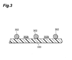
- the reinforcement mesh 302 is placed on a PET film 330 at the beginning.
- the mesh filler 332 is applied to the reinforcement mesh 302 on the PET film 330 with a wire coater so as to fill the openings 302b with the mesh filler 332 (refer to Fig. 4 ).
- DEAA N,N-diethylacrylamide
- DEGV diethylene glycol monovinyl ether
- DEGV polyethylene glycol
- PEG polyethylene glycol
- HEAA N,N-hydroxyethylacrylamide
- HEAA is preferred as a material for the mesh filler 332.
- the use of HEAA ensures mesh-filling of the reinforcement mesh.
- HEAA is diluted with ethanol such that HEAA in the form of a coating medium has a concentration of 80 wt%.
- the mesh-filling level (the amount of the mesh filler 332 filling in the openings 302b) of the reinforcement mesh 302 can be adjusted, so that the thickness of the permselective membrane 13a to be formed is adjustable.
- the mesh filler 332 applied to the reinforcement mesh 302 is heat-treated to volatilize the diluent solvent (ethanol) from the mesh filler 332 filled in the opening 302a to reduce the volume of the mesh filler 332. It is preferred to form exposed portions 302c in the reinforcement mesh 302 by partially exposing the reinforcement mesh 302 originally covered with the mesh filler 332 with reducing the volume of the mesh filler 332, in the process to reduce the volume of the mesh filler 332 filled in the opening 302a.
- ethanol diluent solvent
- the mesh filler 332 shrinks during heat treatment such as drying, whereby exposed portions 302c of the reinforcement mesh 302 can be readily formed by means of the volume shrinkage of the mesh filler 332. Furthermore, the process removing the portions of the mesh filler 332 covering the reinforcement mesh 302 is not necessary, because the exposed portions are formed before the formation of the permselective membrane 13a by means of the volume shrinkage of the mesh filler 332. In the subsequent process, the permselective membrane 13a is fixed to the reinforcement mesh 302 by bonding the exposed portion 302c with the permselective material.
- the method of forming the exposed portion 302c in the reinforcement mesh 302 is not limited to the volume shrinkage of the mesh filler 332.
- a permselective material 13s in the form of a coating medium is applied with a wire coater so as to cover the exposed portion 302c of the reinforcement mesh 302 and the exposed portion 332a of the mesh filler 332 filled in the opening 302b. Subsequently, a permselective membrane 13a is formed by removing the solvent from the permselective material 13s during the heat treatment.
- the permselective material 13s in the form of a coating medium may further contain a leveling agent.
- the permselective membrane 13a having a level surface can be formed even if the permselective material 13s and the mesh filler 332 have poor bonding capability.
- the PET film 330 is peeled off from the reinforcement mesh having the layered permselective membrane.
- the mesh filler 332 filled in the opening 302b of the reinforcement mesh 302 is removed through water washing from the surface remote from the reinforcement mesh 302 having the layered permselective membrane 13a. After the mesh filler 332 is removed, the reinforcement mesh 302 and the permselective membrane 13a are dried to eliminate water so as to yield a permselective membrane structure 40a, as illustrated in Fig. 7 .
- the method of removing the mesh filler filled in the opening 302b of the reinforcement mesh 302 is not limited to the water washing.
- the mesh filler 332 may be washed and removed with any solvent or chemical which can dissolve the constituents of the mesh filler 332.
- the portions to be removed in the mesh filler 332 applied to the reinforcement mesh 302 may be reformed by irradiation with UV (ultra violet rays) or EB (electron beams) into a form that can be readily removed before the removal of these portions.
- the mesh filler 332 is filled in the opening 302b of the reinforcement mesh 302 for mesh filling of the reinforcement mesh 302, so that a nearly level surface is formed on the reinforcement mesh 302. Since the permselective membrane 13a is formed of the permselective material 13s after the opening 302b of the reinforcement mesh 302 is filled with the mesh filler 332, excess flow of the permselective material 13s in the form of a coating medium into the opening 302b of the reinforcement mesh 302 (to the extent of filling up the opening 302b) does not occur. Consequently, the permselective membrane 13a having a uniform thickness and a level surface can be formed.
- a membrane-formable material having a viscosity controlled using a solvent for optimal process conditions has been used.
- a membrane-formable material having a low viscosity containing a relatively large amount of solvent has been used. It has been difficult, however, to apply the membrane-formable material having a low viscosity to the substrate having a large diameter of an opening such as the reinforcement mesh, due to its surface tension and fluidity. Since the applied membrane-formable material flows into the openings of the reinforcement mesh, a layered structure of the reinforcement mesh and the membrane cannot be attained.
- the formation of the permselective membrane 13a using the permselective material 13s after the opening 302b of the reinforcement mesh 302 is filled with the mesh filler 332 can control the flow of the permselective material 13s into the opening 302b of the reinforcement mesh 302, solving the disadvantages inherent with a conventional method.
- the gas permeability of the permselective membrane 13a facing the opening 302b of the reinforcement mesh 302 can be ensured by removing the mesh filler 332 from the opening 302b of the reinforcement mesh 302 after formation of the permselective membrane 13a.
- the volume shrinkage ratio of the mesh filler 332 can be controlled during the volume shrinkage of the mesh filler 332 filled in the opening 302b, by adjusting the amount of the solvent that dilutes the mesh filler 332.
- the volume of the space formed in the opening 302b of the reinforcement mesh 302 accompanied with the volume shrinkage of the mesh filler 332 can, therefore, be controlled, so that the volume of the permselective material 13s to be introduced into the space is adjustable.
- the thickness of the permselective membrane 13a after the membrane formation is adjustable. Furthermore, the introduction of the permselective material 13s into the space formed in the opening 302b of the reinforcement mesh 302 due to the volume shrinkage of the mesh filler 332 generates a structure of the reinforcement mesh 302 stuck in the permselective membrane 13a after the membrane formation. Since this structure has an anchor effect, the permselective membrane 13a can be attached firmly to the reinforcement mesh 302.
- the second method of making a permselective membrane structure 40a in accordance with an embodiment of the present invention is described. Differences between the first method and the second method are described below, while the description on the common steps in the both methods is skipped.
- the permselective membrane 13a is formed to cover the exposed portion 332a of the mesh filler 332 filled in the opening 302b directly, while in the second method the permselective membrane 13a is formed to cover an intermediate layer formed preliminarily on the exposed portion 332a of the mesh filler 332 filled in the opening 302b.
- the second method is different from the first method in this regard.
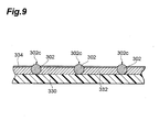
- the second method of making a permselective membrane structure 40a comprises the steps of filling openings 302b of a reinforcement mesh 302 with a mesh filler 332; forming an intermediate layer 334 capable of bonding both the mesh filler 332 and a permselective material 13s on exposed portions 332a of the mesh filler 332 filled in the opening 302b; reducing the volume of the mesh filler 332 filled in the opening 302b; forming a permselective membrane 13a of a permselective material 13s so as to cover exposed portions 302c of the reinforcement mesh 302 uncovered with the mesh filler and the intermediate layer 334; and removing the mesh filler 332 and the intermediate layer 334 from the openings 302b of reinforcement mesh 302 after formation of the permselective membrane 13a.
- these steps of the second method in accordance with an embodiment of the present invention are described below.
- the mesh filler 332 is applied to the reinforcement mesh 302 on the PET film 330 with a wire coater, so that the mesh filler 332 is filled in the opening 302b of the reinforcement mesh 302.
- the intermediate layer 334 includes any layer capable of bonding both the mesh filler 332 and the permselective material 13s, for example, a layer containing polyvinyl alcohol (hereinafter referred to as PVA).
- the intermediate layer 334 containing PVA be thinned so as to be removed easily in a subsequent step, and have a thickness in the range of preferably about 0.01 ⁇ m to 30 ⁇ m.
- An example of the PVA use in the intermediate layer 334 includes a known PVA having a degree of polymerization ranging from about 400 to 4000 and a degree of saponification not less than 80 mol%.
- a PVA having high solubility in water for example, a PVA having a degree of polymerization ranging from about 100 to 400 and a degree of saponification ranging from about zero to 90 mol%.
- a PVA having a degree of polymerization ranging from about 200 to 250 and a degree of saponification of about 81 mol% JL-05E made by Japan Vam & Poval Co., Ltd
- a PVA having a degree of polymerization ranging from about 200 to 250 and a degree of saponification of about 88 mol% ASP05 made by Japan Vam & Poval Co., Ltd
- a denatured-PVA having functional groups other than hydroxyl groups and acetyl groups of a normal PVA may be used.
- the solvent contained in the mesh filler 332 filled in the opening 302b and the intermediate layer 334 is removed during the heat treatment to reduce the volume of the mesh filler 332 and the intermediate layer 334, thereby the exposed portions 302c of the reinforcement mesh 302 is formed (refer to Fig. 9 ).
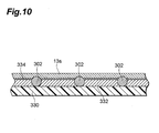
- the permselective material 13s in the form of a coating medium is applied with a wire coater so as to cover the exposed portions 302c of the reinforcement mesh 302 and the intermediate layer 334.
- the solvent of the permselective material 13s is removed during the heat treatment, so that the permselective membrane 13a is formed of the permselective material 13s (refer to Fig. 10 ).
- the PET film 330 is peeled off from the reinforcement mesh 302 having the layered permselective membrane 13a.
- the mesh filler 332 filled in the opening 302b of the reinforcement mesh 302 and the intermediate layer 334 located behind are removed through water washing from the surface remote from the reinforcement mesh 302 having the layered permselective membrane 13a.
- the reinforcement mesh 302 and the permselective membrane 13a are dried to remove water, thereby a permselective membrane structure 40a is yielded, as illustrated in Fig. 7 .
- the above mentioned second method has the same advantages of the invention achieved by the first method. Furthermore, since the permselective material 13s is formed on the surface of the intermediate layer 334 capable of bonding the mesh filler 332 and the permselective material 13s in the second method, the permselective material 13s can be readily formed into a membrane, resulting in ready fabrication of a permselective membrane 13a having an even thickness and a smooth surface.
- the permselective membrane 13a is formed so as to cover directly the exposed portions 302c of the reinforcement mesh 302 and the exposed portions 332a of the mesh filler filled in the opening 302b using a permselective material 13s that cannot be readily bonded to the mesh filler 332, the permselective material 13s is not easily formed into a membrane on the surface of mesh filler 332 due to the difficulty in bonding between the mesh filler 332 and the permselective material 13s.
- the second method is free from this problem, because the permselective material is formed on the surface of the intermediate layer capable of bonding both the mesh filler 332 and the permselective material 13s.
- the intermediate layer 334 may be etched through the reinforcement mesh 302 as a mask such that the intermediate layer 334 remains between the permselective membrane 13a and the reinforcement mesh 302.
- an adhesive material as the intermediate layer 334 (i.e. a material developing adhesiveness under a secondary load such as a thermal load) enables the permselective membrane 13a to adhere (fix) to the reinforcement mesh 302.
- the ventilation system of the present invention is provided with a membrane formed of the permselective material that supplies gas to a space to be ventilated and/or discharges the gas from the space.
- the membrane is placed at an intake of the external air (an external air inlet).
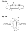
- Examples of the space to be ventilated include spaces requiring the exchange of the gas in the space for external air, such as vehicles (cars), housings, bullet trains, and airplanes, and more specifically a vehicle as is illustrated in Fig. 11 .
- Fig. 11 is a schematic cross-sectional view taken along the longitudinal direction of a vehicle in accordance with an embodiment of the ventilation system of the present invention.
- the interior 19 of the vehicle 10 includes an interior wall 11 and a permselective membrane (permeable membrane) 13 (composed of the permselective material of the present invention), so that the external air is substantially blocked over places other than the permselective membrane 13 installed for intake of the external air.
- the interior wall 11 is composed of materials such as iron, aluminum, and glass which are substantially impermeable to gas.
- the permselective membrane 13 is composed of the above-mentioned permselective material having a thickness in the range of preferably 0.1 ⁇ m to 10 ⁇ m. Examples of the actual place for the installation of the permselective membrane 13 in the vehicle 10 include an external air inlet in an air-conditioning unit illustrated in Fig. 12 .
- Fig. 12 is a schematic cross-sectional view illustrating part of an air-conditioning unit 30 in a vehicle in accordance with an embodiment of the ventilation system of the present invention.
- the air conditioning unit 30 includes an air-conditioning unit case 35, a centrifugal blower fan 37, and a permeable member 400.
- the air-conditioning unit case 35 has an external air inlet 35a, an internal air inlet 35b, and an opening 35c.
- the centrifugal blower fan 37 is installed in a circulating pathway of the internal air in the air-conditioning unit case 35.
- the permeable member 400 is installed in the air-conditioning unit case 35 so as to block the external air inlet 35a.
- Such an air-conditioning-unit 30 can take in the external air from the external air inlet 35a through the permeable member 400 and the internal air from the internal air inlet 35b, so that the external air and/or the internal air is supplied to the vehicle interior through the opening 35c.
- the internal air may be discharged to the outside from the external air inlet 35a through the permeable member 400 in some cases.
- the air-conditioning unit case 35 is composed of a resin having some extent of elasticity and high mechanical strength, such as polypropylene.
- the centrifugal blower fan 37 may be a conventional fan used for the circulation of the internal air in a vehicle.
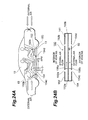
- Any permeable member 400 having the permselective membrane 13 through which the external air can be introduced is usable. Examples of such members include permeable members 400a and 400b, respectively, of which permselective membrane 13 backed with base 42a and 42b as illustrated in Figs. 13 and 14 , and the permselective membrane structure 40a made by the above-mentioned method.
- FIG. 13 is a perspective view illustrating a preferred embodiment of the permeable member 400.
- a permeable member 400a in accordance with this embodiment includes a permselective membrane 13a and a base 42a.
- the permselective membrane 13a has a planar shape, and is backed with the planar base 42a attaching closely to a surface of the plane.
- the base 42a may be attached closely to parts of the permselective membrane 13a, for example, peripheries of the permselective membrane 13a, or the entire permselective membrane 13a.
- Fig. 14 is a perspective view illustrating another preferred embodiment of the permeable member 400.
- the permeable member 400b in accordance with this embodiment includes a permselective membrane 13b and a base 42b.
- the permselective membrane 13b is serrated, and is backed with the serrated base 42b attaching closely to a surface of the membrane.
- the base 42b may be attached closely to part or all of the permselective membrane 13b.
- the permselective membranes 13a and 13b are composed of the membrane formed of the above-mentioned permselective material having a thickness in the range of preferably 0.1 ⁇ m to 10 ⁇ m.
- the base 42a and 42b may be composed of any gas permeable material. Examples of material for the base include fibrous sheets, and porous materials and meshes having a pore diameter in the range of 0.1 ⁇ m to 500 ⁇ m.
- the thickness of the base is in the range of preferably 50 ⁇ m to 500 ⁇ m.
- the permselective membranes 13a and 13b which are backed with the base in the permeable members 400a and 400b, respectively, can be thinned to increase the volume of permeable gas while ensuring the strength of the permselective membrane structure. Furthermore, the increased surface area of the permselective membranes 13a and 13b in the permeable member 400b enables the volume of permeable gas to further increase.
- the permselective membrane structure can be made, for example, through the steps of forming a permselective membrane on a removable film by the above- mentioned method of forming and processing a membrane, transferring a base on the formed permselective membrane, and removing the film.
- the removable films include films that can be removed by washing with water, solvents, or chemicals, and films that can be removed after reforming by irradiation with UV or EB.
- Examples of transferring the base on the permselective membrane include bonding between the permselective membrane and the base with an adhesive or tackiness agent and bonding the permselective membrane to the base by heating or dissolution with a solvent.
- the permselective membrane 13 in the vehicle 10 may be installed in a ventilation equipment for pressure regulation ( Fig. 15 ), a ceiling ( Figs. 16 to 18 ), a glass ( Figs. 19 to 21 ), a pillar ( Figs. 22 and 23 ), a floor ( Fig. 24 ) and a door ( Figs. 25 to 29 ).
- the permselective membrane 13 to be installed may be used alone, in the form of the permselective members 400a and 400b backed with the above mentioned base, or in the form of the permselective membrane structure 40a prepared by the method described above. The places of installation are described below in detail.
- Fig. 15 is an outline schematic view illustrating a vehicle, which is an embodiment of a ventilation system of the present invention, provided with a permselective membrane made of a permselective material of the present invention in ventilation equipment for pressure regulation.
- the ventilation equipment for pressure regulation 110 in accordance with this embodiment is disposed on both sides of a vehicle 10 in the vicinity of the rear bumper 34.
- the ventilation equipment for pressure regulation 110 includes a frame 38, a damper 32, and a permselective membrane 13.
- the ventilation equipment for pressure regulation 110 is mounted in the nearly rectangular cutout provided in a body 122 of the vehicle 10. More specifically, the frame 38 of the ventilation equipment for pressure regulation 110 is a rectangular pipe of which the edge face, remote from the vehicle 10, is equipped with a flange. The flange is fixed to the body 122, for example, by welding.
- an edge (the back edge), not the edge fixed to the body 122, of the bottom portion is bent obliquely upward toward the vehicle interior 19.
- the bent portion is referred to as a damper receiver 38a.
- the lower edge of the damper 32 comes into contact with the damper receiver 38a from the exterior to the interior 19 of the vehicle 10 when the door is shut.
- the damper 32 is fixed to the frame 38 with the hinge 32a. More specifically, the upper side of the damper 32 and the back inside of the upper wall of the parallelepiped frame 38 are connected to a hinge 32a, so that the damper 32 is pivoted around the hinge 32a.
- the pressure in the vehicle interior 19 does not increase while the door is kept closed, so that no pressure is applied to the damper 32 from the vehicle interior 19.
- the damper 32 is pivoted toward the vehicle interior 19 around the hinge 32a by its own weight. Through the pivoting of the damper 32, the lower end of the damper 32 is put into contact with the damper receiver 38a to stop further pivoting. Consequently, the damper 32 comes to the closed position, which is illustrated as a position ⁇ in Fig. 15B , so that the vehicle interior 19 is kept airtight.
- Figs. 16 to 18 are outline schematic views illustrating a vehicle, which is an embodiment of a ventilation system of the present invention, provided with a permselective membrane made of a permselective material of the present invention in the ceiling.
- a permselective membrane made of a permselective material of the present invention in the ceiling.
- the vehicle 10 in accordance with this embodiment is provided with the permselective membrane 13 in the ceiling. Implementations of ceilings in accordance with this embodiment are described below.
- the ceiling of the vehicle 10 in Implementation 1A has a cavity 70, and includes an external air inlet 26 and an external air outlet 28 disposed at portions of an exterior wall 22 of the vehicle 10, and a permselective membrane disposed at a portion of the cavity 70.
- the cavity 70 is defined by the interior wall 24 facing the vehicle interior 19 in the ceiling of the vehicle 10 and the exterior wall 22 facing outward.
- the exterior wall 22 and the interior wall 24 are composed of gas impermeable materials such as iron, aluminum, and glass.
- the external air inlet 26 is a hole provided in the exterior wall 22 defining the cavity 70 in order to introduce the external air to the cavity 70 from the traveling direction of the vehicle 10, while the external air outlet 28 is a hole provided in the exterior wall 22 defining the cavity 70 in order to discharge the external air introduced into the cavity 70 to the opposite direction of the traveling.
- the external air inlet 26 and the external air outlet 28 are substantially rectangular holes which have a long side in the lateral direction of the vehicle 10, the lengths of the long side and the short side being determined by the type of vehicle and the volume of the external air to be introduced into the cavity 70.
- the permselective membrane 13 is disposed in the interior wall 24 such that at least part of the permselective membrane 13 is in contact with the external air introduced into the cavity 70 through the external air inlet 26 and the remaining parts are in contact with the air in the vehicle interior 19.
- a portion of the interior wall 24 of the vehicle 10 is cut out nearly into a substantially square shape.
- the permselective membrane 13 of the substantially square shape having the same size of the cut out portion of the interior wall 24 is provided and is reinforced at the peripheries.
- the reinforcements to reinforce the peripheries of the permselective membrane 13 one in the traveling direction of the vehicle 10 is hereinafter referred to as a front reinforcement 12a and one in the direction opposite to the traveling direction of the vehicle 10 as a rear reinforcement 12b.
- the permselective membrane 13 having the reinforced peripheries is fixed to the substantially rectangular hole of the interior wall 24.
- the cutout portion of the interior wall 24 has the substantially rectangular shape in this implementation, the shape of the cutout portion is not limited. The portion can be cut out into other shapes corresponding to the shape of the ceilings, for example, a circle, a trapezoid, or a complex shape composed of a number of lines and curves.
- FIG. 17 the ventilation system preventing water drops from coming in the cavity 70 through the external air inlet 26 and the external air outlet 28 is described.
- Figs. 17A to C illustrate the structure to prevent water drops from coming in the cavity 70.
- Fig. 17A illustrates means to prevent water drops from coming in the cavity 70 having a front flapper 27a and a rear flapper 27c in this embodiment (Implementation 2A).
- the front flapper 27a and the rear flapper 27c, respectively, are fixed to the exterior wall 22 with hinges 27b and 27d so as to open or close along the traveling direction of the vehicle 10 by pivoting around the hinges 27b and 27d.
- the fixing position of the hinge 27b is located behind the external air inlet 26 and in front of the front reinforcement 12a along the traveling direction of the vehicle 10.
- the fixing position of the hinge 27d is located in front of the external air outlet 28 and behind the rear reinforcement 12b along the traveling direction of the vehicle 10.
- the front flapper 27a and the rear flapper 27c are actuated by the external air pressure. More specifically, the external air is introduced into the cavity 70 through the external air inlet 26 while the vehicle 10 is moving. The external air introduced through the inlet 26 hits against the front flapper 27a. Consequently, the pressure caused by the external air on the surface of the front flapper 27a facing the external air inlet 26 allows the flapper 27a to open.
- the rear flapper 27c also, is actuated by the external air introduced to the cavity 70 in the same way as the front flapper 27a.
- the maximum angle ⁇ when the front flapper 27a is open is determined by the position of the front reinforcement 12a. More precisely, the lower end of the front flapper 27a resides in front of the front reinforcement 12a in the traveling direction of the vehicle 10 when the flapper 27a opens fully, so that the maximum angle ⁇ is determined.
- Fig. 17B illustrates an embodiment of use of weirs as means to prevent water drops from coming in. More specifically, the front weir 27e is disposed between the external air inlet 26 and the front reinforcement 12a, while the rear weir 27f is disposed between the rear reinforcement 12b and the external air outlet 28 in this embodiment
- the front weir 27e includes a pair of substantially rectangular slender plates disposed in sequence in the direction of traveling of the vehicle 10.
- the pair of plates is fixed so as to dispose their long sides in the width direction of the vehicle 10.
- One of the pair of plates, i.e. the plate disposed adjacent to the external air inlet 26, is fixed to the exterior wall 22 of the vehicle 10, with a clearance to the interior wall 24.
- the plate disposed adjacent to the permselective membrane 13 is fixed to the interior wall 24 of the vehicle 10, with a clearance to the exterior wall 22.
- each length of the plates is slightly greater than the length of the permselective membrane 13 in the width direction of the vehicle 10, so that the permselective membrane 13 is protected against the invasion of water drops.
- the rear weir 27f is composed of a single plate.
- the plate is fixed to the end of the exterior wall 22 defining the external air outlet 28 extending downward and diagonally forward in the direction of traveling of the vehicle 10.
- This plate also, has a length greater than the length of the permselective membrane 13 in the width direction of the vehicle 10.
- the water drops contained in the external air introduced in the cavity 70 are removed with the plate on the side of the external air inlet 26 defining the front weir 27e, fall onto the outer surface of the interior wall 24, and then are discharged to a drain (not shown in the drawing) outside the vehicle 10 via the outer surface of the interior wall 24.
- the remaining water drops not removed by the plate on the side of the external air inlet 26 are removed with the plate on the side of the permselective membrane 13, fall onto the outer surface of the interior wall 24, and are discharged to a drain (not illustrated) outside the vehicle 10 via the outer surface of the interior wall 24. Consequently, no water drop comes in the cavity 70 through the external air inlet 26.
- the rear weir 27f can prevent the raindrops from splattering on the outer panel of the vehicle 10 rather than the water drops contained in the external air introduced to the external air outlet 28 incoming.
- the plates fixed to the end of the external air outlet 28 can thereby prevent invasion of water drops to the cavity 70.
- Examplementation 4A introduction of the external air to the cavity 70 in response to the oxygen concentration in the vehicle interior 19 is described.
- the ventilation system in Implementation 4A includes the ventilation system in Implementations 1A to 3A, a front fan 29a, a rear fan 29b, an oxygen sensor 18, and a control unit 90.
- the front fan 29a and the rear fan 29b control the volume of the external air introduced to the cavity 70 based on a command to take in the external air.
- the front fan 29a is disposed between the external air inlet 26 and the front reinforcement 12a in the cavity 70 as in the front weir in Implementation 3A (refer to Fig. 17B ).
- the rear fan 29b is disposed between the external air outlet 28 and the rear reinforcement 12b in the cavity 70 as illustrated in Fig. 17C .
- the oxygen sensor 18 measuring the oxygen concentration in the vehicle interior 19 is mounted in the dashboard of the vehicle 10 as illustrated in Fig. 16 .
- the control unit 90 outputting the command to take in the external air toward the front fan 29a and the rear fan 29b when the measured oxygen concentration in the vehicle interior 19 with the oxygen sensor 18 is at the predefined level is composed of CPU (Central Processing Unit), ORM (Object/Relational Mapping), RAM (Random Access Memory), and I/O (Input/Output) and etc.
- the control unit 90 is mounted in the dashboard of the vehicle 10 as illustrated in Fig. 16 .
- the information of the oxygen concentration measured with the oxygen sensor 18 is sent to the control unit 90.
- the control unit 90 determines whether the oxygen concentration is under the predefined level or not, based on the information of the oxygen concentration sent from the oxygen sensor 18. When the determination is made that the oxygen concentration is under the predefined level, a command to take in the external air is output to the front fan 29a and the rear fan 29b so that the external air is introduced to the cavity 70. In contrast, when the control unit determines that the oxygen concentration is above the predefined level, no command to take in the external air is output to the front fan 29a and the rear fan 29b.
- the term "predefined level” means an oxygen concentration necessary for the comfort of the vehicle interior 19.
- the front fan 29a and the rear fan 29b operate when receiving the command from the control unit 90, so as to take in more external air to the cavity 70 compared to the external air inlet 26 installed alone.
- the ventilation system in Implementation 4A introduces the external air to the cavity 70 only at an oxygen concentration below the predefined level in the vehicle interior 19. Since the external air containing certain amounts of hydrocarbons does not always come into contact with the permselective membrane 13, hydrocarbons are not always adsorbed or absorbed with the permselective membrane 13. Consequently, the deterioration of the selective separation ability of the permselective membrane 13 is retarded, resulting in a longer operating life of the permselective membrane 13.
- a carbon dioxide sensor may be used instead of the oxygen sensor 18 to introduce the external air to the cavity 70 with the front fan 29a and the rear fan 29b operating when the carbon dioxide concentration in the vehicle interior 19 increases.
- the oxygen sensor 18 or the carbon dioxide sensor may be replaced with another sensor such as a sensor for the concentration of fine solid components or a counter of the numbers of fine solid components, to introduce the external air to the cavity 70 in response to the observed concentration and etc.
- a part of the inner wall 24 of the ceiling 10 is composed of the permselective membrane 13.
- holes may be provided in the ceiling of the interior wall 24.
- a filter to remove the dust particles larger than the fine solid components may be installed on the surface of the permselective membrane 13.
- the ceiling part of the interior wall 24 may be cut out and infilled with a mesh material on which the permselective membrane 13 to be disposed.
- Fig. 19 is an outline schematic view of a vehicle (Implementation 1B), as an embodiment of the ventilation system of the present invention, provided with a permselective membrane made of a permselective material of the present invention in the windshield.
- the permselective membrane 13 is installed in the lower part of the windshield of the vehicle 10 accompanied by a cover 112, an external air inlet 126, an external air outlet 128, a front weir 127a, and a rear weir 127b.
- the cover 112 shields the permselective membrane 13 on a side facing the external air in order to block the water drops.
- the cover 112 is substantially rectangular viewed from the front side and is curved along the windshield 130 viewed from the side of the vehicle 10.
- the lengths of the long and short sides of the cover 112 are slightly greater than the lengths of the long and short sides of the planar permselective membrane 13 to be described below, so that one surface of the planar permselective membrane 13 can be covered entirely.
- the external air inlet 126 to introduce the external air to the space 120 shielded with cover 112 (hereinafter referred to the space 120) is disposed, while at the end in the opposite direction of traveling of the vehicle, the external air outlet 128 to discharge the external air introduced to the space 120.
- the external air inlet 126 and the external air outlet 128 are slender holes in a substantially rectangular shape having a long side in the lateral direction of the vehicle 10.
- the size of the holes i.e. the lengths of the long and short sides are determined depending on the type of vehicle and the volume of the external air to be introduced to the space 120.
- the front weir 127a is disposed in the vicinity of the space 120 of the external air inlet 126, while the rear weir 127b is disposed outside the windshield 130 in the space 120 close to the upper boundary between the windshield 130 and the permselective membrane 13.
- the front weir 127a includes a substantially rectangular slender plate disposed along in the direction of traveling of the vehicle 10.
- the plate is fixed so as to dispose its long side in the width direction of the vehicle 10 with a clearance to the permselective membrane 13.
- the length of the long side of the plate is slightly greater than the length of the permselective membrane 13 in the width direction of the vehicle 10, so that the permselective membrane 13 is protected against the invasion of water drops.
- the rear weir 127b includes a similar plate to the front weir 127a. These plates, also, have a length greater than the length of the permselective membrane 13 in the width direction of the vehicle 10. Due to the front weir 127a, the water drops contained in the external air introduced to the space 120 is removed, fall onto the outer surface of the body of the vehicle 10, and then are discharged to a drain (not shown in the drawing) outside the vehicle 10 via the outer surface of the body.
- the water drops to come in the space 120 via the outer surface of the windshield 130 are blocked, and are discharged to a drain (not illustrated) outside the vehicle 10.
- the permselective membrane 13 constitutes part of the windshield 130 of the vehicle 10. More specifically, with reference to Fig. 19B , a lower part of the windshield 130 of the vehicle 10 is cut out in a substantially rectangular shape having a long side in the width direction of the vehicle 10. Then, the permselective membrane 13 has a substantially rectangular planar shape having the same size as that of the substantially rectangular cutout windshield 130, so as to fit in the cutout part of the windshield 130.
- the sizes of the permselective membrane 13, i.e. the lengths of the long and short sides are determined by the type of vehicle 10 and the volume of the air introduced to the space 120.
- a rear windshield 139 formed of a permselective membrane 13 on a porous glass sheet 132 in the embodiment (Implementation 2B) is described below.
- Fig. 20 is an outline schematic view illustrating the rear windshield 139 including the porous glass 132 provided with the permselective membrane 13.
- the glass part in the rear windshield 139 illustrated in Fig. 20A is replaced with a porous glass sheet 132 provided with the permselective membrane 13 as illustrated in Fig. 20B .
- the porous glass sheet 132 has fine pores over the entire mass that can pass the air in both directions to and from the vehicle interior 19.
- the permselective membrane 13 is in close contact with the entire surface of the porous glass sheet 132 facing the vehicle interior 19.
- a reinforcement 134 formed of a mesh material is provided on the permselective membrane 13 on the porous glass sheet 132 facing the vehicle interior 19.
- a dust protective filter 136 may be disposed between the reinforcement mesh 134 and the permselective membrane 13 illustrated in Fig. 20B .
- the dust protective filter 136 can prevent the dust in the vehicle interior 19 from attaching directly to the permselective membrane 13.
- the permselective membrane 13 may be sandwiched between two porous glass sheets 132a and 132b, thereby the porous glass sheet 132a, the permselective membrane 13, and the porous glass sheet 132b are stacked in sequence.
- a sliding roof 138 formed of the permselective membrane 13 provided on a porous glass sheet 132 in the embodiment (Implementation 3B) is described below.
- Fig. 21 is an outline schematic view illustrating the sliding roof 138 including the porous glass sheet 132 provided with the permselective membrane 13.
- the glass part in the sliding roof 138 illustrated in Fig. 21B is replaced with the porous glass 132 provided with the permselective membrane 13 as illustrated in Fig. 21A , and the interior wall 24 of the vehicle 10 defining the sliding roof 138 is provided with many holes.
- the external air thus, flows along the outer surface of the porous glass 132 as the sliding roof 138, in a direction opposite to the traveling direction of the vehicle. During this period, the air in the vehicle interior 19 is exchanged with the external air through the permselective membrane 13.
- Fig. 22 is a schematic cross-sectional view illustrating a vehicle, which is an embodiment of the ventilation system of the present invention, provided with a permselective membrane made of a permselective material of the present invention in a pillar.
- the vehicle 10 includes a vehicle 10 that is surrounded by substantially non-permeable walls of aluminum and glass and that blocks ambient air, and spaces outside the vehicle interior 19 such as a trunk and an engine compartment, wherein the spaces allow ambient air to enter.
- Parts of the walls defining the vehicle interior 19 include pillars 50, 52, and 54.
- the front pillars 50 are disposed at both ends of the windshield in the front section of the vehicle interior 19, the central pillars 52 roughly in the center of the long sides of the windows on both sides of the vehicle 10, and the rear pillars 54 at both ends of the rear windshield in the rear section of the vehicle interior 19.
- the vehicle 10 is provided with an air conditioner, also (not shown in the drawing).
- the air conditioner circulates the interior air only.
- Fig. 23A is an outline schematic view illustrating the vehicle 10 and pillars 50, 52, and 54 in the vehicle 10
- Fig. 23B is an outline schematic view illustrating a pattern of the structure of the central pillar 52.
- the vehicle 10 is provided with the front pillar 50, the central pillar 52, and the rear pillar 54. Since each pillar 50, 52, and 54 has the same structure, the central pillar 52 is described below in details as an example with reference to Fig. 23B .
- the central pillar 52 forms a hollow cylinder having an elliptical upper end 52e and an elliptical lower end 52f.
- An external air intake 52a and an external air outlet 52b are disposed in the side face, remote from the vehicle interior 19, of the cylinder, while an internal air intake 52c and an internal air outlet 52d are disposed in the side face, adjacent to the vehicle interior 19, of the cylinder.
- the external air intake 52a is disposed at the lower part of the central pillar 52, while the external air outlet 52b is disposed at the upper part of the central pillar 52.
- the internal air intake 52c is disposed at the lower part of the central pillar 52, while the internal air outlet 52d is disposed at the upper part of the central pillar 52.
- the permselective membrane 13 is installed in the hollow portion of the central pillar 52 so as to separate the external air taken in through the external air intake 52a and discharged to the external air outlet 52b from the internal air taken in through the intake 52c and discharged to the outlet 52d.
- the permselective membrane 13 is disposed such that the upper and lower ends of the permselective membrane 13 are aligned to the major axes of the elliptical upper and lower ends 52e and 52f, respectively of the central pillar 52.
- the upper end of the permselective membrane 13 is in close contact with the inner surface of the elliptical upper end 52e of the central pillar 52 with an adhesive, while the lower end of the permselective membrane 13 is in close contact with the inner surface of the elliptical lower end 52f of the central pillar 52 with an adhesive.
- the upper and lower ends of the permselective membrane 13 is in close contact with the minor arc inside the cylinder of the central pillar 52 having elliptic cross sections along the axis of the cylinder with an adhesive.
- Fig. 23B schematically illustrates a planar permselective membrane 13, a bellows membrane may be used.
- a temperature sensor 60 is provided on the surface, remote from the vehicle interior 19, of the permselective membrane 13, and two fans 56a and 56b are provided in the central pillar 52.
- the temperature sensor 60 such as a thermocouple or Peltier device is used for measuring the surface temperature of the permselective membrane 13 and outputting electric signals converted from the temperature.
- the fan 56a and 56b are provided in the pathway introducing the external air from the external air intake 52a to the external air outlet 52b and in the pathway circulating the internal air from the internal air intake 52c and the internal air outlet 52d, respectively.
- the fans 156a and 156b cool (air-cool) the permselective membrane 13 by taking in the external air from the external air intake 52a and the internal air from the intake 52c.
- the front pillar 50 and the rear pillar 54 can be described in the same way as the central pillar 52, which is described above as an example.
- Fig. 24 is a schematic cross-sectional view illustrating a vehicle, which is an embodiment of the ventilation system of the present invention, provided with a permselective membrane made of a permselective material of the present invention in a floor.
- Fig. 24A is a schematic longitudinal cross-sectional view of the vehicle 10
- Fig. 24B is an enlarged view of the floor 150.
- the vehicle 10 includes the vehicle interior 19 that is surrounded by substantially non-permeable walls of aluminum and glass and that blocks ambient air, and spaces outside the vehicle interior 19 such as a trunk and an engine compartment, wherein the spaces allow ambient air to enter.
- a floor 150 of the vehicle interior 19 defines a space 141 between a floor panel 152 and an outer plate 154.
- the vehicle 10 is provided with an air conditioner, also (not shown in the drawing). This air conditioner circulates the interior air only.
- Fig. 24B is an outline schematic view illustrating a structure of the floor 150.
- the floor 150 includes a floor panel 152 adjacent to the vehicle interior 19 and an outer plate 154 remote from the vehicle interior 19.
- the floor panel 152, the outer plate 154, and side plates 153a and 153b define the space 141 between the floor panel 152 and the outer plate 154, and the permselective membrane 13 is disposed in the space 141.
- the floor panel 152 is provided with an internal air intake 152a taking in the internal air to the space 141 from the vehicle interior 19 and an internal air outlet 152b discharging the internal air taken in the space 141 to the vehicle interior 19.
- the internal air intake 152a is disposed in front of the driving seat in the direction of traveling of the vehicle 10, more specifically under the driver feet. Meanwhile, the internal air outlet 152b is disposed at the back of the driving seat in the direction of traveling of the vehicle 10, more specifically right in front of the rear seat.
- the outer plate 154 defining the space 141 includes the external air intake 154c taking in the external air into the space 141 from the outside of the vehicle interior 19 and the external air outlet 154d discharging the external air taken in the space 141 to the outside of the vehicle interior 19.
- the external air intake 154c is disposed in front of the driving seat in the direction of traveling of the vehicle 10, more specifically under the driver feet. Meanwhile, the external air outlet 154d is disposed at the back of the driving seat in the direction of traveling of the vehicle 10, more specifically right in front of the rear seat.
- the permselective membrane 13 is disposed in the space 141 so as to separate the vehicle interior 19 from the outside of the vehicle interior 19. More specifically, the side ends of the permselective membrane 13 are in close contact with the inner surfaces, adjacent to the space, of the side plates 153a and 153b, which define the space 141, with an adhesive or a seal material.
- Fig. 24B schematically illustrates a planar permselective membrane 13, a bellows membrane may be used.
- a temperature sensor 60 is provided on the surface, remote from the vehicle interior 19, of the permselective membrane 13, and two fans 156a and 156b are provided in the space 141.
- a temperature sensor 60 such as a thermocouple, a platinum resistive element, or a thermistor is used for measuring the surface temperature of the permselective membrane 13 and outputting electric signals converted from the surface temperature.
- the fan 156a and 156b are provided in the pathway for circulating the internal air from the internal air intake 152a to the internal air outlet 152b and in the pathway for introducing the external air from the external air intake 154c to the external air outlet 154d, respectively.
- the fans 156a and 156b cools (air-cool) the permselective membrane 13 by taking in the external air from the intake 154c and the internal air from the intake 152a.
- Fig. 25A is a side view illustrating a vehicle 10, which is an embodiment of a ventilation system of the present invention, provided with a permselective membrane made of a permselective material of the present invention in the door, while Fig. 25B is a schematic cross-sectional view of a door 140 taken along the width direction of the vehicle 10.
- the ventilation system includes an interior component 164, a permselective membrane 13, an external air intake 52a, and an external air outlet 52b disposed on a door 140.
- a window 80 made of glass is attached roughly on the central line of the door 140.
- the external air intake 52a is a hole to take in the external air outside the vehicle interior 19, disposed in the upper part of the door 140 remote from the vehicle interior 19 relative to the window 80.
- the external air outlet 52b is a hole to discharge the external air taken in from the external air intake 52a, disposed in the lower part of the door 140 remote from the vehicle interior 19 relative to the window 80.
- the interior component 164 is provided on a surface of the vehicle interior 19, and is made of an air-permeable material. More particularly, the component is composed of an inorganic or organic compound having a form of porous object, fiber, thin film, or a composite thereof. Although the interior component 164 is not particularly limited provided that air can pass through its fine pores, it is preferred that the size of the pores be in the range from several tens of nanometers to several hundred nanometers.
- the interior component 164 is provided with a deodorant 17 supported on the inner wall of the pores.
- the deodorant 17 is a heated catalyst composed of one or more oxides of copper, manganese, platinum, nickel, iron, tantalum, aluminum, and titanium.
- the deodorant 17 is supported on the interior component 164 made of a porous inorganic compound.
- the diameter of the pores of the inorganic porous component is not limited provided that the supply of the gas to the permselective membrane 13 is not impaired, it is preferred that the diameter be in the range from several tens of micrometers to several hundred micrometers.
- the permselective membrane 13 is in close contact with the surface, remote from the vehicle interior 19, of the interior component 164.
- planar permselective membrane 13 is accordion-folded, so that the plane is disposed roughly in parallel with the flow of the external air introduced from the outside of the vehicle interior 19, i.e. the ridge lines of the bellows are disposed roughly in parallel with the air flow.
- the door 140 is provided with the permselective membrane 13 in close contact with the surface, remote from the vehicle interior 19, of the interior component 164, and the external air intake 52a and the external air outlet 52b are disposed remote from the vehicle interior 19 relative to the window 80; whereby the side adjacent to the vehicle interior 19 is separated from the side remote from the vehicle interior 19 in the door 140 and the external air introduced from the external air intake 52a hits against the surface, remote from the vehicle interior 19, of the permselective membrane 13.
- the external air introduced from the external air intake 52a comes in contact with the surface, remote from the vehicle interior 19, of the permselective membrane 13.
- the external air in contact with the surface, remote from the vehicle interior 19, of the permselective membrane 13 is discharged from the external air outlet 52b.
- the volume of external air introduced from the external air intake 52a increases, so that the external air continues to hit against the surface, remote from the vehicle interior 19, of the permselective membrane 13.
- the supply of the external air containing certain amounts of oxygen, carbon dioxide, and fine solid components to the surface, remote from the vehicle interior 19, of the permselective membrane 13 is kept.
- the permselective membrane 13 can maintain the concentrations of oxygen and carbon dioxide in the vehicle interior 19 at the same levels as the concentrations in the external air while the vehicle 10 is moving, without a blower introducing the external air into the vehicle interior 19. Since no blower is required, the load for a battery of the vehicle can be reduced.
- the deodorant 17 supported in the fine pores of the porous object of the interior component 164 can remove malodorous components contained in the external air, which enters the vehicle interior 19 through the permselective membrane 13. Since no malodorous component enters the vehicle interior 19, the vehicle interior 19 can be maintained at comfort.
- the accordion-folded permselective membrane 13 can increase the surface area of the permselective membrane 13. Since the large surface area of the permselective membrane 13 increases the exchange volumes of oxygen and carbon dioxide, changes in the concentrations of oxygen and carbon dioxide in the vehicle interior 19 can be adjusted to certain levels for a short time.
- Fig. 26A is a side view illustrating a vehicle 10
- Fig. 26B is a schematic cross-sectional view illustrating a door 140 taken along the width direction of the vehicle 10.
- Fig. 27 is a schematic cross-sectional view illustrating another door 140 taken along the width direction of the vehicle 10.
- a ventilation system in accordance with the Implementation 2C is provided with a dust removal filter 14 in close contact with a surface, remote from the vehicle interior 19, of a permselective membrane 13.
- the dust removal filter 14 is a membranous member having pores greater than the fine pores in the permselective membrane 13, the membranous member including, for example, an activated carbon fiber, a nonwoven fabric, a plastic fiber, or a charged fiber; and a fibrous, nonwoven, planar, undulant, or granular substrate.
- plastic fiber examples include polypropylene, nylons, polyesters, polyvinyl chloride, polyvinylidene chloride, polyethylene, polyvinylidene fluoride, and acrylic plastics. These plastic fibers are braided alone or in combination of two or more.
- Examples of the charged fiber include electret fibers of polymers such as polypropylene charged by an electro-electret method, in which ions are forcibly implanted from an external electrode.
- Examples of the polymer include fluorine resins, silicone resins, epoxy resins, polyolefins, polystyrene derivatives, polystyrene, polyamides, polyvinyl halides, polyurethanes, polyvinyl chloride, and polycarbonates, in addition to polypropylene.
- Examples of the electrification method for the charged fiber include a photo-electret method involving irradiation of an electric field with UV rays, a mechano-electret method causing a plastic flow by an applied stress, a thermo-electret method involving application of a high electric field to the polymer at an increased temperature, a magnet-electret method involving application of a magnet field at an increased temperature, and a radio-electret method involving irradiation with electromagnetic rays such as ⁇ rays, in addition to the electro-electret method.
- a dehumidifier 16 may be disposed in close contact with the surface, remote from the vehicle interior 19, of the permselective membrane 13.
- the dehumidifier 16 is in close contact with the surface, remote from the vehicle interior 19, of the permselective membrane 13, and removes the moisture contained in the external air which comes in contact with the surface, remote from the vehicle interior 19, of the permselective membrane 13. More specifically, examples of the dehumidifier 16 include; mixtures of water-absorbing polymers, cotton pulp, feed-water paper, silica gel, calcium oxide, magnesium oxide, or calcium chloride with porous materials; water-absorbing polymers such as electrolytic polymers or hydrophilic polymers; acrylic polymers; vinyl alcohol; or a polymer of acrylic acid. Such a dehumidifier 16 is stacked on the surface, remote from the vehicle interior 19, of the permselective membrane 13.
- the moisture contained in the external air which comes in contact with the surface, remote from the vehicle interior 19, of the permselective membrane 13 can be removed, so that no water attaches to the surface of the permselective membrane 13. Consequently, the gas permeability of the permselective membrane 13 can be kept.
- an optional blower 118 may be provided in the vicinity of the surface, remote from the vehicle interior 19, of the permselective membrane 13.
- the blower 118 provided in the vicinity of the surface, remote from the vehicle interior 19, of the permselective membrane 13 supplies the air from the outside of the vehicle interior 19 through the external air intake 52a to the surface, remote from the vehicle interior 19, of the permselective membrane 13.
- This configuration allows the blower 118 to feed the external air remote from the vehicle interior 19 to the permselective membrane 13. Since the fresh air continues to hit against the surface, remote from the vehicle interior 19, of the permselective membrane 13, the concentrations of oxygen and carbon dioxide remote from the vehicle interior 19 are kept constant at the surface, remote from the vehicle interior 19, of the permselective membrane 13. Consequently, changes in the concentrations of oxygen and carbon dioxide in the vehicle interior 19 can be recovered to certain levels for a short time. Furthermore, since no water enters the vehicle interior through the permselective membrane 13, the clouding of the window 80 of the vehicle interior 19 can be prevented.
- FIG. 28A is a side view illustrating a vehicle 10
- Fig. 28B is a schematic cross-sectional view of a door 140 taken along the width direction of the vehicle 10.
- Fig. 29 is a schematic cross-sectional view of another door 140 taken along the width direction of the vehicle 10.
- the door 140 has a space 151 which is defined by an outer wall 50a remote from the vehicle interior 19 and an inner wall 50b adjacent to the vehicle interior 19.
- An external air intake 52a is disposed in a lower position of the outer wall 50a above the external air outlet 52b.
- the external air outlet 52b is provided in a lower position of the outer wall 50a, and the permselective membrane 13 is disposed diagonally from the upper right to the bottom left in the space 151 in the drawing so as to cover the external air intake 52a and the external air outlet 52b.
- the overall surface, adjacent to the vehicle interior, of the permselective membrane 13 is reinforced with a reinforcement 13c. Furthermore, a heat accumulator 15 is provided in the portions between the permselective membrane 13 and the outer wall 50a.
- the reinforcement 13c is composed of one or more materials selected from polyolefins, polycarbonates, polyether sulfones, polyvinylidene fluoride, polyethylene, fluorine resins (e.g. PTFE and PEF), glass (e.g. glass fiber), and cellulose.
- the reinforcement 13c has a porous structure, of which the diameter of the fine pores is in the range, for example, from several nanometers to several hundred nanometers.
- the heat accumulator 15 heats the permselective membrane 13 directly or indirectly through the reinforcement 13c.
- the heat accumulator 15 accumulates the heat supplied from outside, to heat the permselective membrane 13 by the accumulated heat.
- the accumulator is composed of a material of which thermal conductivity is higher than those of the permselective membrane 13 and the reinforcement 13c, such as a honeycomb ceramic, inorganic hydrated salt, paraffin or wax supported on a porous object.
- the heat accumulator 15 stores the radiation heat from the sun as external heat. Consequently, when the permselective membrane 13 is disposed inside the door 140, the radiation heat from the sun, which shines above the vehicle 10, is accumulated.
- a dehumidifier 16 on the surface, remote from the vehicle interior 19, of the permselective membrane 13 can remove the moisture contained in the external air which comes in contact with the surface, remote from the vehicle interior 19, of the permselective membrane 13, so that no water attaches to the surface of the permselective membrane 13. Consequently, the gas permeability of the permselective membrane 13 can be kept.
- an optional blower 118 may be provided over the surface, adjacent to the vehicle interior 19, of reinforcement 13c.
- the blower 118 which suctions the external air to the vehicle interior 19 increases the volume of the external air introduced from the external air intake 52a in contact with the surface, remote from the vehicle interior 19, of the permselective membrane 13.
- the volume of oxygen introduced to the vehicle interior 19 and the volume of carbon dioxide discharged from the vehicle interior 19 increase, so that changes in the concentrations of oxygen and carbon dioxide in the vehicle interior 19 can be recovered to certain levels for a short time.
- gas is discharged and introduced through the permselective membrane made of the permselective material of the present invention. Consequently, the suspended materials such as SPM and nSPM in the air does not flow into the vehicle interior, and the suspended materials such as SPM and nSPM in the vehicle interior, if present, can be removed.
- Silicone modified pullulan polymer (X-22-8400 available from Shin-Etsu Chemical Co., Ltd.) was dissolved in toluene into a solid content of 1 wt%.
- 0.196 g of spherical silica (X-24-9163A available from Shin-Etsu Chemical Co., Ltd., average diameter: 110 nm) [163 parts by mass for 100 parts by mass of silicone modified pullulan polymer (50 vol% to silicone modified pullulan polymer)] was compounded, and the mixture was agitated with an ultrasonic homogenizer.
- the resulting solution was placed into a Teflon (Registered Trade Mark by Du Pont, USA) petri dish (diameter: 90 mm), and toluene was removed using a vacuum drier. A membrane having an average thickness of 25 ⁇ m was yielded.
- Silicone modified pullulan polymer (X-22-8400 available from Shin-Etsu Chemical Co., Ltd.) was dissolved in toluene into a solid content of 1 wt%.
- 0.098 g of mesoporous silica prepared in Synthetic Example 2A [82 parts by mass for 100 parts by mass of silicone modified pullulan polymer (50 vol% to silicone modified pullulan polymer)] was compounded, and the mixture was agitated with an ultrasonic homogenizer.
- the resulting solution was placed into a Teflon (Registered Trade Mark by Du Pont, USA) petri dish (diameter: 90 mm), and toluene was removed using a vacuum drier.
- a membrane having an average thickness of 25 ⁇ m was yielded.
- Silicone modified pullulan polymer (X-22-8400 available from Shin-Etsu Chemical Co., Ltd.) was dissolved in toluene into a solid content of 1 wt%.
- 0.098 g of mesoporous silica prepared in Synthetic Example 2A subjected to hydrophobic treatment with 3-aminopropyltriethoxysilane (KBE903 available from Shin-Etsu Chemical Co., Ltd.) [82 parts by mass for 100 parts by mass of silicone modified pullulan polymer (50 vol% to silicone modified pullulan polymer)] was compounded, and the mixture was agitated with an ultrasonic homogenizer.
- the resulting solution was placed into a Teflon (Registered Trade Mark by Du Pont, USA) petri dish (diameter: 90 mm), and toluene was removed using a vacuum drier. A membrane having an average thickness of 25 ⁇ m was yielded.
- Silicone modified pullulan polymer (X-22-8400 available from Shin-Etsu Chemical Co., Ltd.) was dissolved in toluene into a solid content of 10 wt%.
- a conductive polymer polyaniline (emeraldine base available from Aldrich, molecular weight: 20000) was dissolved in cyclohexanone into a solid content of 2 wt%.
- To 0.6 ml of the silicone modified pullulan polymer solution, 0.4 ml of the polyaniline solution [13.3 parts by mass for 100 parts by mass of silicone modified pullulan polymer (40 vol% to the silicone modified pullulan polymer)] was compounded, and the mixture was agitated with an ultrasonic homogenizer.
- a film was formed on a polycarbonate support (Isopore available from Japan Millipore Ltd., average pore diameter: 0.22 ⁇ m) by a water surface process. Toluene and cyclohexanone were removed using a drier to yield a membrane having an average diameter of 0.1 ⁇ m.
- Silicone modified pullulan polymer (X-22-8400 available from Shin-Etsu Chemical Co., Ltd.) was dissolved in toluene into a solid content of 10 wt%.
- a conductive polymer polyaniline (emeraldine base available from Aldrich, molecular weight: 20000) was dissolved in cyclohexanone into a solid content of 2 wt%.
- To 0.6 ml of the silicone modified pullulan polymer solution, 0.4 ml of the polyaniline solution [13.3 parts by mass for 100 parts by mass of silicone modified pullulan polymer (40 vol% to silicone modified pullulan polymer)] was compounded.
- the silicone modified cycloolefin polymer prepared in Synthetic Example 1A was dissolved in toluene into a solid content of 10 wt%.
- a conductive polymer polyaniline (emeraldine base available from Aldrich, molecular weight: 20000) was dissolved in cyclohexanone into a solid content of 2 wt%.
- a film was formed on a polycarbonate support (Isopore available from Japan Millipore Ltd., average pore diameter: 0.22 ⁇ m) by a water surface process. Toluene and cyclohexanone were removed using a drier to yield a membrane having an average diameter of 0.1 ⁇ m.
- the silicone modified cycloolefin polymer prepared in Synthetic Example 1A was dissolved in toluene into a solid content of 10 wt%.
- a conductive polymer polyaniline (emeraldine base available from Aldrich, molecular weight: 20000) was dissolved in cyclohexanone into a solid content of 2 wt%.
- To 0.6 ml of the silicone modified pullulan polymer solution, 0.4 ml of the polyaniline solution [13.3 parts by mass for 100 parts by mass of silicone modified pullulan polymer (40 vol% to silicone modified cycloolefin polymer)] was compounded.
- a silicone modified pullulan polymer (X-22-8400 available from Shin-Etsu Chemical Co., Ltd.) was dissolved in toluene into a solid content of 1 wt%. The solution was placed into a Teflon (Registered Trade Mark by Du Pont, USA) petri dish (diameter: 90 mm), and toluene was removed using a vacuum drier. A membrane having an average thickness of 15 ⁇ m was yielded.
- the silicone modified cycloolefin polymer prepared in Synthetic Example 1A was dissolved in toluene into a solid content of 1 wt%. The solution was placed into a Teflon (Registered Trade Mark by Du Pont, USA) petri dish (diameter: 90 mm), and toluene was removed using a vacuum drier. A membrane having an average thickness of 15 ⁇ m was yielded.
- Example 8A to 12A and Comparative Examples 3A to 8A Silicone modified pullulan polymer (X-22-8400 available from Shin-Etsu Chemical Co., Ltd.) was dissolved in toluene into a solid content of 1 wt%. To 12 g of this solution, a predetermined amount of additive shown in Table 4 was added, followed by mixing with an ultrasonic homogenizer. The resulting filler-containing solution was placed into a Teflon (Registered Trade Mark by Du Pont, USA) petri dish (diameter: 90 mm), and toluene was removed using a vacuum drier. A membrane having an average thickness of 20 to 30 ⁇ m was yielded for each example.
- Teflon Registered Trade Mark by Du Pont, USA
- the silicone modified cycloolefin polymer prepared in Synthetic Example 1A was dissolved in toluene into a solid content of 10 wt%.
- a conductive polymer polyaniline (emeraldine base available from Aldrich, molecular weight: 20000) was dissolved in cyclohexanone into a solid content of 2 wt%.
- the silicone modified cycloolefin polymer prepared in Synthetic Example 1A was dissolved in toluene into a solid content of 10 wt%.
- a conductive polymer polyaniline (emeraldine base available from Aldrich, molecular weight: 20000) was dissolved in cyclohexanone into a solid content of 2 wt%.
- the silicone modified cycloolefin polymer prepared in Synthetic Example 1A was dissolved in toluene into a solid content of 10 wt%.
- a conductive polymer polyaniline (emeraldine base available from Aldrich, molecular weight: 20000) was dissolved in cyclohexanone into a solid content of 2 wt%.
- the silicone modified cycloolefin polymer prepared in Synthetic Example 1A was dissolved in toluene into a solid content of 10 wt%.
- a conductive polymer polyaniline (emeraldine base available from Aldrich, molecular weight: 20000) was dissolved in cyclohexanone into a solid content of 2 wt%.
- Example 16A A higher permeability in Example 16A than that is Example 14A is probably affected by new gaps that are generated between silica or polyaniline particles.
- Silicone modified pullulan polymer (X-22-8400 available from Shin-Etsu Chemical Co., Ltd.) was dissolved in toluene into a solid content of 10 wt%.
- a conductive polymer polyaniline (emeraldine base available from Aldrich, molecular weight: 20000) was dissolved in cyclohexanone into a solid content of 2 wt%.
- To 0.6 ml of the silicone modified pullulan polymer solution 0.4 ml of the polyaniline solution (13.3 parts by mass for 100 parts by mass of silicone modified pullulan polymer) was compounded. To 1 mL of this solution, a predetermined amount of acid shown in Table 8 was added, and the mixture was agitated with an ultrasonic homogenizer.
- a film was formed on a polycarbonate support (Isopore available from Japan Millipore Ltd., average pore diameter: 0.22 ⁇ m) by a water surface process. Toluene and cyclohexanone were removed using a drier to yield a membrane having an average diameter of 0.1 ⁇ m.
- the silicone modified cycloolefin polymer prepared in Synthetic Example 1A was dissolved in toluene into a solid content of 10 wt%.
- a conductive polymer polyaniline (emeraldine base available from Aldrich, molecular weight: 20000) was dissolved in cyclohexanone into a solid content of 2 wt%.
- Example 1B Silicone modified pullulan polymer (X-22-8400 available from Shin-Etsu Chemical Co., Ltd.) was dissolved in toluene into a solid content of 10 wt%. To the resulting solution, 20 parts by mass of ionic liquid 1-ethyl-4-methylimidazolium nitrate (available from Kanto Chemical Co., Inc., melting point: 38°C) was added for 100 parts by weight of silicone modified pullulan polymer.
- ionic liquid 1-ethyl-4-methylimidazolium nitrate available from Kanto Chemical Co., Inc., melting point: 38°C
- the resulting solution containing ionic liquid was placed into a Teflon (Registered Trade Mark by Du Pont, USA) petri dish (diameter: 90 mm), and toluene was removed using a drier at a temperature (for example, 60°C) that is higher than the melting point of the ionic liquid.
- a drier at a temperature (for example, 60°C) that is higher than the melting point of the ionic liquid.
- a membrane having an average thickness of 15 ⁇ m was yielded. After evaporation of the organic solvent, the membrane was allowed to stand at a temperature (for example, 25°C) below the melting point of the ionic liquid to solidify the ionic liquid.
- Silicone modified pullulan polymer (X-22-8400 available from Shin-Etsu Chemical Co., Ltd.) was dissolved in toluene into a solid content of 10 wt%. To the resulting solution, 20 parts by mass of ionic liquid 1-ethyl-4-methylimidazolium phosphate (available from Kanto Chemical Co., Inc., melting point: 58-60°C) was added for 100 parts by weight of silicone modified pullulan polymer.
- the resulting solution containing ionic liquid was placed into a Teflon (Registered Trade Mark by Du Pont, USA) petri dish (diameter: 90 mm), and toluene was removed using a drier at a temperature (for example, 70°C) that is higher than the melting point of the ionic liquid.
- a drier at a temperature (for example, 70°C) that is higher than the melting point of the ionic liquid.
- a membrane having an average thickness of 15 ⁇ m was yielded. After evaporation of the organic solvent, the membrane was allowed to stand at a temperature (for example, 25°C) below the melting point of the ionic liquid to solidify the ionic liquid.
- Silicone modified cycloolefin polymer (X-22-1960 available from Shin-Etsu Chemical Co., Ltd.) was dissolved in toluene into a solid content of 10 wt%. To the resulting solution, 20 parts by mass of ionic liquid 1-ethyl-4-methylimidazolium nitrate (available from Kanto Chemical Co., Inc., melting point: 38°C) was added for 100 parts by weight of silicone modified cycloolefin polymer.
- the resulting solution containing ionic liquid was placed into a Teflon (Registered Trade Mark by Du Pont, USA) petri dish (diameter: 90 mm), and toluene was removed using a drier at a temperature (for example, 60°C) that is higher than the melting point of the ionic liquid.
- a drier at a temperature (for example, 60°C) that is higher than the melting point of the ionic liquid.
- a membrane having an average thickness of 15 ⁇ m was yielded. After evaporation of the organic solvent, the membrane was allowed to stand at a temperature (for example, 25°C) below the melting point of the ionic liquid to solidify the ionic liquid.
- Silicone modified cycloolefin polymer (X-22-1960 available from Shin-Etsu Chemical Co., Ltd.) was dissolved in toluene into a solid content of 10 wt%. To the resulting solution, 20 parts by mass of ionic liquid 1-ethyl-4-methylimidazolium phosphate (available from Kanto Chemical Co., Inc., melting point: 58-60°C) was added for 100 parts by weight of silicone modified cycloolefin polymer.
- the resulting solution containing ionic liquid was placed into a Teflon (Registered Trade Mark by Du Pont, USA) petri dish (diameter: 90 mm), and toluene was removed using a drier at a temperature (for example, 70°C) that is higher than the melting point of the ionic liquid.
- a drier at a temperature (for example, 70°C) that is higher than the melting point of the ionic liquid.
- a membrane having an average thickness of 15 ⁇ m was yielded. After evaporation of the organic solvent, the membrane was allowed to stand at a temperature (for example, 25°C) below the melting point of the ionic liquid to solidify the ionic liquid.
- Silicone modified pullulan polymer (X-22-8400 available from Shin-Etsu Chemical Co., Ltd.) was dissolved in toluene into a solid content of 1 wt%. The resulting solution was placed into a Teflon (Registered Trade Mark by Du Pont, USA) petri dish (diameter: 90 mm), and toluene was removed using a vacuum drier (for example, 60°C). A membrane having an average thickness of 15 ⁇ m was yielded.
- Teflon Registered Trade Mark by Du Pont, USA
- Silicone modified cycloolefin polymer (X-22-1960 available from Shin-Etsu Chemical Co., Ltd.) was dissolved in toluene into a solid content of 1 wt%.
- the resulting solution containing ionic liquid was placed into a Teflon (Registered Trade Mark by Du Pont, USA) petri dish (diameter: 90 mm), and toluene was removed using a drier (for example, 60°C).
- a drier for example, 60°C
- silicone modified pullulan polymer (X-22-8400 available from Shin-Etsu Chemical Co., Ltd.) was dissolved in toluene into a content of silicone modified pullulan polymer (solid content) of 10 wt%.
- a content of silicone modified pullulan polymer solid content of 10 wt%.
- 0.098 g of the mesoporous silica described above 81.7 parts by mass of mesoporous silica for 100 parts by mass of solid component of silicone modified pullulan resin) was compounded.
- the mixture was agitated with an ultrasonic homogenizer to prepare a permselective material.
- a mesh filler coating is applied to openings of the PET 64-HC placed on the PET film with a wire coater, to fill the openings of the PET 64-HC with the mesh filler coating.
- the mesh filler coating used is a 50 wt% HEAA resin (solid component) solution in ethanol.
- the mesh filler coating applied to the PET 64-HC is heat-treated to evaporate ethanol diluent from the mesh filler coating in the openings of the PET 64-HC, whereby exposed portions of the PET 64-HC was formed through a reduction in volume of the mesh filler.
- the permselective material was coated with a wire coater so as to cover the exposed portions of the PET 64-HC and the exposed portions of the mesh filler material in the openings.
- the solvent toluene is removed by heat treatment from the permselective material to prepare a permselective membrane from the permselective material.
- the PET film was separated from a laminate of the PET 64-HC and the permselective membrane.
- the mesh filler in the openings of the PET 64-HC is removed by water washing from a surface remote from the permselective film. After the mesh filler is removed, the PET 64-HC and the permselective membrane were dried to prepare a permselective membrane structure of Example 1C.
- the average thickness of the permselective membrane of the permselective membrane structure was controlled to 3.8 ⁇ m.
- Permselective membrane structures of Examples 2C to 4C and 7C to 9C were prepared as in Example 1C except that the type of the reinforcement mesh, the type of the resin contained in the mesh filler coating, the content (wt%) of the resin (solid component) in the mesh filler coating, the type of the additive contained in the permselective material, the amount (parts by mass) of the additive for 100 parts by mass of silicone modified pullulan resin solid component are modified as shown in Table 10.
- NanoTek SiO 2 shown in Table 10 is an additive available from C.I. Chemicals.
- Example 5C a permselective membrane structure was prepared as in Example 1C except that the type of the reinforcement mesh, the type of the resin contained in the mesh filler coating, the content (wt%) of the resin (solid component) in the mesh filler coating, the type of the additive contained in the permselective material, the amount (parts by mass) of the additive for 100 parts by mass of silicone modified pullulan resin solid component were modified as shown in Table 10.
- the permselective membrane structure of Example 5C was prepared by another method different from that in Example 1C, as follows:
- a mesh filler coating is applied to PET 85-HC on the PET film to fill the openings of PET 85-HC with the mesh filler coating.
- a coating that is adhesive to both the mesh filler and the permselective material is applied onto PET 85-HC coated with the mesh filler coating to form an intermediate layer from this coating.
- the thickness of the intermediate layer was about 2.6 ⁇ m.
- the coating for the intermediate layer was an aqueous solution containing 20 wt% PVA (JL-05E available from Japan VAM & POVAL Co., Ltd.) that was adhesive to both the mesh filler HEAA and the permselective material.
- the solvent component contained in the mesh filler in the openings of PET 85-HC and the intermediate layer was removed through heat treatment, whereby exposed portions of PET 85-HC were formed by the volume shrinkage of the mesh filler and the intermediate layer.
- the permselective material was applied with a wire coater so as to cover the exposed portions of PET 85-HC and the intermediate layer.
- the solvent component in the permselective material was removed by heat treatment; thereby a permselective membrane was formed of the permselective material.
- the PET film was removed from PET 85-HC provided with the permselective membrane.
- the mesh filler in the opening of the PET 85-HC and the inner intermediate layer were removed by water washing from the free surface, remote from the permselective membrane of the PET 85-HC. After the removal of the mesh filler and the intermediate layer, the PET 85-HC and the permselective membrane were dried; thereby a permselective membrane structure of Example 5C was formed.
- a permselective membrane structure of Example 6C was formed as in Example 5C except that the coating for forming the intermediate layer was an aqueous 20 wt% PVA (ASP05 available from Japan VAM & POVAL Co., Ltd.) solution.
- the coating for forming the intermediate layer was an aqueous 20 wt% PVA (ASP05 available from Japan VAM & POVAL Co., Ltd.) solution.
- permselective membrane structures were formed as in Example 1C except that the type of the reinforcement mesh, the type of the resin contained in the mesh filler coating, the content (wt%) of the resin (solid components) in the mesh filler coating, the type of the additive contained in the permselective material, the content of the additive (parts by mass) for 100 parts by mass of the silicone modified pullulan resin solid component were modified as shown in Table 10. Furthermore, in Comparative Examples 1C and 2C, the permselective material was directly applied to the reinforcement mesh without treatment with mesh filler.
- each permselective membrane structure had permselective membrane having a smooth surface with a uniform thickness, without excess flow of the permselective material into the opening of the reinforcement mesh.
- Examples 1C to 6C using a HEAA resin solution in ethanol as a mesh filler it was confirmed that mesh-filling was ensured by the mesh filler and the permselective membrane was satisfactorily formed.
- a permselective membrane structure of Example 3a was prepared as in Example 3C except that the thickness of the permselective membrane was modified to a value shown in Table 11.
- a permselective membrane structure of Example 4a was prepared as in Example 4C except that the thickness of the permselective membrane was modified to a value shown in Table 11.
- a permselective membrane structure of Example 6a was prepared as in Example 6C except that the thickness of the permselective membrane was modified to a value shown in Table 11.
- a permselective membrane structure of Example 1a was prepared as in Example 1C except that the thickness of the permselective membrane was modified to a value shown in Table 11.
- permselective membrane structures were prepared as in Example 1C except that no mesh filler was used and the type of the reinforcement mesh, the type of the additive contained in the permselective material, and the content (parts by mass) of the additive for 100 parts by mass of silicone modified pullulan resin solid component were modified as shown in Table 12. Furthermore, in Reference Examples 1C to 3C, the permselective membrane structure was prepared by the following process different from that in Example 1C. In Reference Examples 1C to 3C, a water-miscible PVA film was formed on an removable PET film as a support by a coater process. The average thickness of the PVA film is shown in Table 12.
- a permselective material shown in Table 12 was applied onto the PVA film by a coater process to form a permselective membrane. After the permselective membrane was transferred onto a reinforcement mesh (PET 85-HC), it was dipped into water to dissolve the PVA film. Accordingly, a permselective membrane structure was formed.
- each permselective membrane structure had a uniform thickness with a smooth surface. It was confirmed that the amount of the residue of the PVA film remaining on the produced permselective membrane structure was reduced as the thickness of the water-miscible PVA film on the exfoliate PET film was reduced.
Landscapes
- Chemical & Material Sciences (AREA)
- Chemical Kinetics & Catalysis (AREA)
- Engineering & Computer Science (AREA)
- Inorganic Chemistry (AREA)
- Mechanical Engineering (AREA)
- Organic Chemistry (AREA)
- Analytical Chemistry (AREA)
- Manufacturing & Machinery (AREA)
- Physics & Mathematics (AREA)
- Acoustics & Sound (AREA)
- Dispersion Chemistry (AREA)
- General Chemical & Material Sciences (AREA)
- Oil, Petroleum & Natural Gas (AREA)
- Separation Using Semi-Permeable Membranes (AREA)
- Air-Conditioning For Vehicles (AREA)
Abstract
wherein when oxygen and nitrogen are passed through a membrane comprising the permselective material, the relation between the permeability coefficients [cm3• cm• sec-1• cm-2• cmHg-1] of oxygen and nitrogen at a temperature of 23±2°C under a pressure difference of 1.05 atm to 1.20 atm through the membrane is expressed by Formula (1):
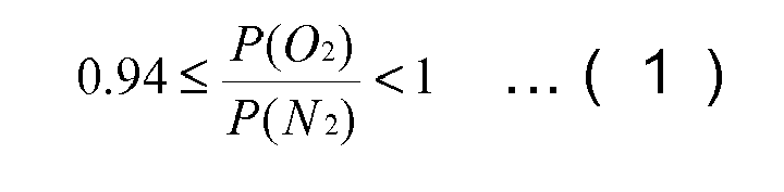
where P(O2) denotes the permeability coefficient of oxygen, while P(N2) denotes the permeability coefficient of nitrogen.
Description
- The present invention relates to a permselective material, a method of making a permselective membrane structure, a permselective membrane structure, and a ventilation system.
- Recently, the advancement of technology has enabled airtightness of spaces such as car interiors of which airtightness had not been able to be successfully achieved. In the case where many passengers stay in a car of which airtightness is high for long hours, external air must be introduced moderately into the interior to prevent the passengers from feeling headache or discomfort resulting from decreased oxygen concentration and increased carbon dioxide concentration.
- However, direct introduction of external air into the car interior caused a significant problem in view of health of the passengers due to contaminants such as dust of urban roads and main roads. A countermeasure to solve such a problem is installation of a filter that removes the contaminants such as the suspended materials at an inlet of external air.
- Conventionally, nonwoven cloth and mechanical filters have been used for the filter. In Patent Literature 1, an overall ventilation system for a car is proposed.
- Patent Literature 1: Japanese Unexamined Patent Application Publication No.
2004-203367 - However, it is significantly difficult for the conventional filters such as nonwoven cloth and mechanical filters to remove suspended material in the air having a diameter not greater than 10 µm (hereinafter referred to as SPM) and especially a diameter not greater than 100 nm (hereinafter referred to as nSPM). When a gas permselective membrane made of polymer material, which can remove SPM and nSPM, is applied to the filter, the sufficient introduction of external air is not attained due to its low gas permeability.
- It is an object of the present invention to provide a permselective material which can form a membrane which can remove suspended material in the air such as SPM and nSPM and has sufficient gas permeability, and a ventilation system using the material.
- The inventors of the present invention have found that the object described above can be attained by a permselective material made of a polymer having an organosiloxane skeleton (hereinafter referred to as silicone polymer if convenient) and a solid additive, so that the flow of the gas passing through the membrane formed of the permselective material is dominated by Knudsen flow. The "solid additive" includes an additive that is solid at normal temperature under normal pressure, but not fluid matter such as a plasticizer and an ionic liquid. The Knudsen flow represents a flow of sufficiently rarefied gas which can be readily affected by molecular motion (refer to "Kagaku Daijiten" edited by Kagaku Daijiten Henshuu Iinkai, vol. 3, p.44 in compact edition), and is characterized by the gas permeation rate depending on the molecular weight. The term "dominated by Knudsen flow" represents that the gas permeation rate depends on the molecular weight.
- The present invention provides a permselective material comprising a silicone polymer containing a dispersed solid additive, and when oxygen and nitrogen are passed through a membrane comprising the permselective material, the relation between the permeability coefficients [cm3• cm• sec-1• cm-2• cmHg-1] of oxygen and nitrogen at a temperature of 23±2°C under a pressure difference of 1.05 atm to 1.20 atm through the membrane is expressed by Formula (1):

where P(O2) denotes the permeability coefficient of oxygen, while P(N2) denotes the permeability coefficient of nitrogen. - Such a permselective material can remove suspended material such as SPM and nSPM in the air, while a membrane having sufficient gas permeability can be formed thereof. The term "sufficient gas permeability" in this description means that the permeability coefficients of oxygen and nitrogen at a temperature of 23±2°C under a pressure difference of 1.05 atm to1.20 atm are not less than 8.0 × 10⁻⁸ [cm3• cm• sec-1• cm-2• cmHg-1], preferably not less than 1.0 × 10⁻⁷ [cm3• cm• sec-1• cm-2• cmHg-1]. The term "can remove suspended material such as SPM and nSPM in the air" in this description means a blocking ratio of nSPM being not less than 80 wt% (preferably not less than 90 wt%, and more preferably not less than 99 wt%). In the case of a blocking ratio of nSPM of not less than 80 wt%, suspended materials having a larger diameter than nSPM such as SPM can be removed as a matter of course. The blocking ratio of nSPM can be measured, for example, by the method described in the Examples.
- When gas passes through the membrane formed of the above-mentioned permselective material, a Knudsen flow occurs in the flow of gas therethrough. In this case, pores causing the Knudsen flow are formed preferably in at least one site selected from the group consisting of a boundary between the silicone polymer and a particle of the solid additive, a boundary between two adjacent particles of the solid additive, a particle itself of the solid additive, and a cell in the silicone polymer, more preferably in a boundary between the silicone polymer and a particle of the solid additive and/or a boundary between two adjacent particles of the solid additive.
- Preferably, the solid additive is a filler, a conductive polymer, or a mixture of them. From a view point of further improving gas permeability, preferably the filler is a silica filler, and more preferably a porous filler. The solid additive being a filler preferably satisfies one of the following conditions (1) to (3):
- (1) The filler is porous silica particles, and the amount of the solid additive is in the range of 25 to 1560 parts by mass for 100 parts by mass of silicone polymer;
- (2) The filler is non-porous silica particle having an average particle diameter of 10 nm to 120 nm with a hydrophobic or hydrophilic surface, and the amount of the solid additive is in the range of 65 to 3800 parts by mass for 100 parts by mass of silicone polymer;
- (3) The filler is non-porous titanium oxide particle having an average particle diameter of 10 nm to 60 nm with a hydrophilic surface, and the amount of the solid additive is in the range of 330 to 6400 parts by mass for 100 parts by mass of silicone polymer.
- Examples of the conductive polymer include polyaniline and acid-treated polyaniline. Polyaniline and acid-treated polyaniline are, similar to silicone polymer, soluble in a solvent such as toluene. Accordingly, polyaniline dissolved in a solvent can be readily and reliably mixed with and dispersed in the silicone polymer.
- The inventors of the present invention has found that the object described above can be achieved with a permselective material composed of a silicone polymer and an ionic liquid, wherein the flow of the gas passing through the membrane formed of the permselective material is dominated by the Knudsen flow.
- The present invention provides a permselective material comprising a silicone polymer containing an ionic liquid additive, and when oxygen and nitrogen are passed through a membrane comprising the permselective material, the relation between the permeability coefficients [cm3• cm• sec-1• cm-2• cmHg-1] of oxygen and nitrogen at a temperature of 23±2°C under a pressure difference of 1.05 atm to 1.20 atm through the membrane is expressed by Formula (1):

where P(O2) denotes the permeability coefficient of oxygen, while P(N2) denotes the permeability coefficient of nitrogen. - Such a permselective material can remove suspended material such as SPM and nSPM in the air, while a membrane having sufficient gas permeability can be formed thereof.
- When gas passes through the membrane comprising the above-mentioned permselective material, a Knudsen flow occurs in the flow of gas therethrough. In this case, pores causing the Knudsen flow are formed preferably in at least one site selected from the group consisting of a boundary between the silicone polymer and the ionic liquid, a boundary between two adjacent ionic liquid regions, the ionic liquid itself, and a cell in the silicone polymer, more preferably in a boundary between the silicone polymer and the ionic liquid and/or a boundary between the two adjacent ionic liquid regions.
- It is assumed that the ionic liquid dispersed in the silicone polymer contributes to the advantageous effect, although the exact reason is not clear. Such dispersion is especially notable when the permselective material of the present invention is prepared using an ionic liquid capable of solidifying and an organic solvent. More specifically, when the organic solvent, in which the ionic liquid is insoluble, is used for silicone polymer (ionic liquids are usually insoluble in a non-polar organic solvent such as toluene.), the ionic liquid is dispersed and separated in a suspended form in the polymer dissolved in such a solvent. When the solvent is evaporated, the ionic liquid is immobilized in the silicone polymer in the separated form. Subsequently, by reducing the temperature of the membrane below the melting point of the ionic liquid, the ionic liquid is solidified, so that a clearance is formed in boundaries between the silicone polymer and the ionic liquid and/or at the interior of the ionic liquid. It is believed that gas flows at high velocity in the clearance. Furthermore, when an ionic liquid region adjoins another ionic liquid region, it is believed that gas flows at high velocity in the clearance. Moreover, when cells are present in the silicone polymer, it is believed that gas flows at high velocity in the cells.
- The ventilation system of the present invention includes a membrane comprising the permselective material that can supply gas to a space to be ventilated and/or can discharge gas from the space. Use of the permselective material of the present invention can block flow of suspended materials such as SPM and nSPM in the air into the space to be ventilated, and can remove suspended materials such as SPM and nSPM, if present, in the space.
- The present invention also provides a method of solving the following problems: Since the airtightness of a vehicle has been enhanced in recent years, a filter and a permselective membrane to remove pollutants in the air such as suspended materials are required to be provided in various places in a vehicle. The filter and the permselective membrane for such applications must have sufficient mechanical strength for various purposes, in addition to capability to remove SPM and nSPM and gas permeability.
In view of such a situation, the present invention provides a method of making a permselective membrane structure, which has gas permeability, capability to remove SPM and nSPM, and sufficient mechanical strength for various purposes, a permselective membrane structure, and a ventilation system having the permselective membrane structure. - The first method of making a permselective membrane structure of the present invention includes the steps of filling openings of a reinforcement mesh with a mesh filler; reducing the volume of the mesh filler filled in the openings; forming a permselective membrane of a permselective material so as to cover exposed portions of the reinforcement mesh uncovered with the mesh filler and exposed portions of the mesh filler filled in the openings; and removing the mesh filler from the openings of the reinforcement mesh after the formation of the permselective membrane. In the present invention, the permselective membrane structure includes the reinforcement mesh and the permselective membrane stacked on the reinforcement mesh. Also, in the present invention, "the opening of the reinforcement mesh" corresponds to the mesh of the reinforcement mesh.
- In the first method, the mesh filler is filled in the opening of the reinforcement mesh for mesh filling of the reinforcement mesh, so that a smooth surface is formed on the reinforcement mesh. Since the permselective membrane is formed of the permselective material after the opening of the reinforcement mesh is filled with the mesh filler, excess flow of the permselective material into the opening of the reinforcement mesh (to an extent of filling-up of the opening) does not occur. Consequently, the permselective membrane having a uniform thickness and a smooth surface can be formed.
- In addition, in the first method, the gas permeability of the permselective membrane facing the opening of the reinforcement mesh can be ensured by removing the mesh filler from the opening of the reinforcement mesh after the formation of the permselective membrane.
- Furthermore, in the first method, the volume shrinkage ratio of the mesh filler can be controlled during the volume shrinkage of the mesh filler filled in the opening, so that the volume of the space formed in the opening of the reinforcement mesh accompanied with the volume shrinkage of the mesh filler can be controlled. The volume of the permselective material to be introduced into the space accompanied with the volume shrinkage of the mesh filler is, thus, adjustable. Consequently, the thickness of the permselective membrane after the membrane formation, more specifically, the thickness of the permselective membrane facing the opening is adjustable. Furthermore, the introduction of the permselective material into the space formed in the opening of the reinforcement mesh due to the volume shrinkage of the mesh filler generates a structure of the reinforcement mesh stuck in the permselective membrane after the formation of the membrane. Since this structure has an anchor effect, the permselective membrane can be attached firmly to the reinforcement mesh.
- The second method of making a permselective membrane structure comprises the steps of filling openings of a reinforcement mesh with a mesh filler; forming an intermediate layer capable of bonding both the mesh filler and a permselective material on exposed portions of the mesh filler filled in the opening; reducing the volume of the mesh filler filled in the opening; forming a permselective membrane of a permselective material so as to cover exposed portions of the reinforcement mesh uncovered with the mesh filler and the intermediate layer; and removing the mesh filler and the intermediate layer from the openings of reinforcement mesh after the formation of the permselective membrane.
- The above mentioned second method also has the advantages of the first method. Furthermore, since the permselective material is formed on the surface of the intermediate layer capable of bonding the mesh filler and the permselective material in the second method, the permselective material can be readily formed into a membrane, resulting in ready fabrication of a permselective membrane having an even thickness and a smooth surface. If the permselective membrane is formed so as to directly cover the exposed portions of the reinforcement mesh and the exposed portions of the mesh filler filled in the opening using a permselective material that cannot be readily bonded to the mesh filler, the permselective material is not easily formed into a membrane on the surface of mesh filler due to the difficulty in bonding between the mesh filler and the permselective material. In contrast, the second method is free from this problem, because the permselective material is formed on the surface of the intermediate layer capable of bonding both the mesh filler and the permselective material.
- In the first and second methods, it is preferred to form exposed portions in the reinforcement mesh by partially exposing the reinforcement mesh originally covered with the mesh filler in the process to reduce the volume of the mesh filler filled in the opening.
- The mesh filler readily shrinks during a treatment such as drying. Exposed portions of the reinforcement mesh can, thus, be readily formed by means of the volume shrinkage of the mesh filler. Furthermore, the process of removing the portions of the mesh filler covering the reinforcement mesh so as to form the exposed portions of the reinforcement and smoothing the surface of the reinforcement mesh by the removal of the mesh filler are not necessary before the formation of the permselective membrane by means of the volume shrinkage of the mesh filler.
- The present invention provides a permselective membrane structure made by the above-mentioned first or second method, wherein a permselective material to form the permselective membrane comprising a silicone polymer containing a dispersed solid additive, and when oxygen and nitrogen are passed through the membrane comprising the permselective material, the relation between the permeability coefficients [cm3• cm• sec-1• cm-2• cmHg-1] of oxygen and nitrogen at a temperature of 23±2°C under a pressure difference of 1.05 atm to 1.20 atm through the membrane is expressed by Formula (1). The width of the opening of the reinforcement mesh is larger than the thickness of the permselective membrane, and the opening ratio of the reinforcement mesh is not less than 30%.

where P(O2) denotes the permeability coefficient of oxygen, while P(N2) denotes the permeability coefficient of nitrogen. - Preferably, the solid additive for the permselective membrane structure is selected from the above-mentioned additives.
- The present invention provides a permselective membrane structure made by the above-mentioned first or second method, wherein a permselective material to form the permselective membrane comprising a silicone polymer containing an ionic liquid additive, and when oxygen and nitrogen are passed through the membrane comprising the permselective material, the relation between the permeability coefficients [cm3• cm• sec-1• cm-2• cmHg-1] of oxygen and nitrogen at a temperature of 23±2°C under a pressure difference of 1.05 atm to 1.20 atm through the membrane is expressed by Formula (1). The width of the opening of the reinforcement mesh is larger than the thickness of the permselective membrane, and the opening ratio of the reinforcement mesh is not less than 30%.

where P(O2) denotes the permeability coefficient of oxygen, while P(N2) denotes the permeability coefficient of nitrogen. - Since the permselective membrane in the permselective membrane structure of the present invention is formed of the above-mentioned permselective material (composed of one of the solid additive or the ionic liquid, and silicone polymer), the flow of the gas passing through the membrane comprising the permselective material is dominated by Knudsen flow. The permselective membrane structure having such a permselective membrane can remove suspended materials such as SPM and nSPM in the air and ensures sufficient gas permeability.
- In order to improve the gas permeability of the permselective membrane, it is necessary to reduce the thickness of the permselective membrane. Although a reduction in thickness of the permselective membrane further improves the gas permeability, it causes a reduction in the strength of the membrane, resulting in ready breakage of the membrane. In the present invention, therefore, the permselective membrane having a small thickness can be reinforced by the permselective membrane structure composed of the permselective membrane layered on the reinforcement mesh. Such a permselective membrane structure can exhibit high strength durable in various applications.
- In the present invention, by the use of the reinforcement mesh having a width of the opening larger than the thickness of the permselective membrane and an opening ratio not less than 30%, the permselective membrane can be reinforced without impairing the gas permeability of the permselective membrane and the gas permeability through the entire permselective membrane structure. In the permselective membrane structure using the reinforcement mesh superior to the porous films and the nonwoven cloth in gas permeability, the gas permeability of the entire permselective membrane structure can, therefore, be improved compared to that of a permselective membrane structure including the permselective membrane reinforced by a porous film or nonwoven cloth.
- The ventilation system of the present invention is provided with the permselective membrane structure of the present invention that supplies gas to a space to be ventilated and/or discharges the gas from the space. Due to the use of the permselective membrane structure of the present invention, the suspended materials such as SPM and nSPM in the air do not flow into the space to be ventilated, and the suspended materials such as SPM and nSPM in the space, if present, can be removed.
- The present invention provides a permselective material which can form a membrane which can remove suspended material such as SPM and nSPM in the air and has sufficient gas permeability, and a ventilation system using the material.
- Furthermore, the present invention provides a method of making a permselective membrane structure, which has gas permeability, a capability to remove SPM and nSPM, and sufficient mechanical strength for the various purposes, a permselective membrane structure made by the method, and a ventilation system having the permselective membrane structure.
-
-
Fig. 1 is an imaginary picture illustrating a gas flow passing through a membrane formed of a permselective material of the present invention. -
Fig. 2 is a schematic perspective view illustrating a permselective membrane structure in accordance with an embodiment of the present invention. -
Fig. 3 is a schematic view illustrating a process in a first method of making a permselective membrane structure in accordance with an embodiment of the present invention. -
Fig. 4 is a schematic view illustrating a process in a first method of making a permselective membrane structure in accordance with an embodiment of the present invention. -
Fig. 5 is a schematic view illustrating a process in a first method of making a permselective membrane structure in accordance with an embodiment of the present invention. -
Fig. 6 is a schematic view illustrating a process in a first method of making a permselective membrane structure in accordance with an embodiment of the present invention. -
Fig. 7 is a schematic cross-sectional view illustrating a permselective membrane structure in accordance with an embodiment of the present invention. -
Fig. 8 is a schematic view illustrating a process in a second method of making a permselective membrane structure in accordance with an embodiment of the present invention. -
Fig. 9 is a schematic view illustrating a process in a second method of making a permselective membrane structure in accordance with an embodiment of the present invention. -
Fig. 10 is a schematic view illustrating a process in a second method of making a permselective membrane structure in accordance with an embodiment of the present invention. -
Fig. 11 is a view illustrating a ventilation system in accordance with an embodiment of the present invention. -
Fig. 12 is a schematic cross-sectional view illustrating part of anair conditioning unit 30 in a vehicle in accordance with an embodiment of the ventilation system of the present invention. -
Fig. 13 is a perspective view illustrating a preferred embodiment of the permselective membrane structure. -
Fig. 14 is a perspective view illustrating another preferred embodiment of the permselective membrane structure. -
Fig. 15 is an outline schematic view illustrating a vehicle provided with a permselective membrane made of a permselective material of the present invention in ventilation equipment for pressure regulation, in an embodiment of a ventilation system of the present invention. -
Fig. 16 is an outline schematic view illustrating a vehicle provided with a permselective membrane made of a permselective material of the present invention in the ceiling, in an embodiment of a ventilation system of the present invention. -
Fig. 17 is an outline schematic view illustrating a vehicle provided with a permselective membrane made of a permselective material of the present invention in the ceiling, in an embodiment of the ventilation system of the present invention. -
Fig. 18 is an outline schematic view illustrating a vehicle provided with a permselective membrane made of a permselective material of the present invention in the ceiling, in an embodiment of the ventilation system of the present invention. -
Fig. 19 is an outline schematic view illustrating a vehicle provided with a permselective membrane made of a permselective material of the present invention in the windshield, in an embodiment of the ventilation system of the present invention. -
Fig. 20 is an outline schematic view illustrating a vehicle provided with a permselective membrane made of a permselective material of the present invention in the rear windshield, in an embodiment of the ventilation system of the present invention. -
Fig. 21 is an outline schematic view illustrating a vehicle provided with a permselective membrane made of a permselective material of the present invention in the sliding roof, in an embodiment of the ventilation system of the present invention. -
Fig. 22 is a schematic cross-sectional view illustrating a vehicle provided with a permselective membrane made of a permselective material of the present invention in the pillar, in an embodiment of the ventilation system of the present invention. -
Fig. 23 is a schematic cross-sectional view illustrating a vehicle provided with a permselective membrane made of a permselective material of the present invention in the pillar, in an embodiment of the ventilation system of the present invention. -
Fig. 24 is a schematic cross-sectional view illustrating a vehicle provided with a permselective membrane made of a permselective material of the present invention in the floor, in an embodiment of the ventilation system of the present invention. -
Fig. 25A is a side view illustrating avehicle 10 provided with a permselective membrane made of a permselective material of the present invention in the door in an embodiment of a ventilation system of the present invention, whileFig. 25B is a schematic cross-sectional view of adoor 140 taken along the width direction of the vehicle. -
Fig. 26 is a schematic cross-sectional view illustrating a vehicle provided with a permselective membrane made of a permselective material of the present invention in the door in an embodiment of a ventilation system of the present invention. -
Fig. 27 is a schematic cross-sectional view illustrating a vehicle provided with a permselective membrane made of a permselective material of the present invention in the door in an embodiment of a ventilation system of the present invention. -
Fig. 28 is a schematic cross-sectional view illustrating a vehicle provided with a permselective membrane made of a permselective material of the present invention in the door in an embodiment of a ventilation system of the present invention. -
Fig. 29 is a schematic cross-sectional view illustrating a vehicle provided with a permselective membrane made of a permselective material of the present invention in the door in an embodiment of a ventilation system of the present invention. -
Fig. 30 is a schematic diagram illustrating a device that measures the shielding rate of nSPM. - 10: vehicle, 11: vehicle interior wall, 12a: front reinforcement, 12b: rear reinforcement, 13, 13a, and 13b: permselective membrane, 13c: reinforcement, 14 and 36: dust removal filter, 16: dehumidifier, 17: deodorant, 18: oxygen sensor, 19: vehicle interior, 20: membrane, 21: silicone, 22: exterior wall, 23: solid additive, 24: interior wall, 25: pore, 26 and 126: external air inlet, 27a: front flapper, 27b and 27d: hinge, 27c: rear flapper, 27e: front weir, 27f: rear weir, 28: external air outlet, 29a: front fan, 29b: rear fan, 30: air-conditioning unit, 32: damper, 32a: hinge, 34: bumper, 35: air-conditioning unit case, 35a: external air inlet, 35b: internal air inlet, 35c: opening, 37: centrifugal blower fan, 38: frame, 40a: permselective membrane structure, 42a and 42b: base, 50: front pillar, 52: central pillar, 52a and 154c: external air intake, 52b, 128, and 154d: external air outlet, 52c and 152a: internal air intake, 52d and 152b: internal air outlet, 52e: top end, 52f: bottom end, 53: side plate, 54: rear pillar, 60: temperature sensor, 70: cavity, 80: window, 90: control unit, 110: ventilating device for pressure regulation, 112: cover, 118: blower, 120: space, 122: vehicle body, 126: external air inlet, 127a: front weir, 127b: rear weir, 130: windshield, 132: porous glass, 138: sliding roof, 140: door, 150: floor, 151: space, 152: floor panel, 154: outer plate, 156a and 156b: fan, 164: interior component, 302: reinforcement mesh, 302b: opening of reinforcement mesh, 302c: exposed reinforcement mesh, 321: silicone polymer, 323: solid additive, 325: pore, 332: mesh filler, 332a: exposed mesh filler, 334: intermediate layer, 400, 400a and 400b: permeable member.
- The present invention is described in detail below with reference to the attached drawings, if necessary, to which the invention is not limited though.
- A permselective material of the present invention is made of silicone polymer containing dispersed solid additives, and when oxygen and nitrogen are passed through a membrane comprising the permselective material, the relation between the permeability coefficients [cm3• cm• sec-1• cm-2• cmHg-1] of oxygen and nitrogen at a temperature of 23±2°C under a pressure difference of 1.05 atm to 1.20 atm through the membrane is expressed by Formula (1):

where P(O2) denotes the permeability coefficient of oxygen, while P(N2) denotes the permeability coefficient of nitrogen. - A permselective material of the present invention may be made of silicone polymer containing ionic liquid additive, and when oxygen and nitrogen are passed through a membrane comprising the permselective material, the relation between the permeability coefficients [cm3• cm• sec-1• cm-2• cmHg-1] of oxygen and nitrogen at a temperature of 23±2°C under a pressure difference of 1.05 atm to 1.20 atm through the membrane is expressed by Formula (1) described above.
- In the following description, when the quotient of the permeability of oxygen divided by the permeability of nitrogen (P(O2)/P(N2), hereinafter also referred to as "separation ratio α") in Formula (1) is equal to or higher than 0.94 and below 1, the flow of the gas passing through the membrane formed of the permselective material is dominated by Knudsen flow. As described above, in the Knudsen flow, the gas permeability rate depends on the molecular weight, and when the flow of gas passing through a membrane is an ideal Knudsen flow, the gas permeability P is inversely proportional to the square root of the molecular weight. For example, the separation ratio α of the passing gas composed of oxygen and nitrogen is 0.935 as is expressed in Formula (2):

where P(O2) and P(N2) denote the permeability coefficients of oxygen and nitrogen, respectively, while M(O2) and M(N2) denote the molecular weights of oxygen and nitrogen, respectively. - In contrast, there is another flow of gas called solution-diffusion flow. The solution-diffusion flow depends on the product of the solubility of gas in a membrane and the diffusion coefficient of gas in the membrane, so that the gas permeability rate in the membrane is generally lower than the rate in a Knudsen flow. In a conventional membrane containing silicone polymer, since the solution-diffusion flow is dominant in the flow of gas passing through the membrane, it is known that the separation ratio α for oxygen and nitrogen is equal to or higher than 1.
- In consideration of these facts, it is predicted that the membrane formed of the permselective material of the present invention, which has a separation ratio α (P(O2)/P(N2)) expressed in the above Formula (1), causes a Knudsen flow when gas passes through the membrane and thus has a significantly improved gas permeability, compared to conventional membranes.
- Although the reason for a Knudsen flow through a membrane formed of the permselective membrane of the present invention is not exactly clear, the view of the inventors is illustrated below using a drawing.
-
Fig. 1 is a schematic cross-sectional view illustrating amembrane 20 formed of a permselective material of the present invention. Themembrane 20 is composed of asilicone polymer 21 and a solidadditive particle 23, having a pore 25 (for example, a pore of 1 nm to 100 nm) that causes a Knudsen flow in the boundaries between them. It is believed that thepore 25 is generated due to low affinity between thesilicone polymer 21 and the solidadditive particles 23. - In such a
membrane 20, gas passes through thesilicone polymer 21 in a solution-diffusion flow regime and through thepore 25 in a Knudsen flow regime. When the solidadditive particle 23 has permeable properties itself such as porous matter, it is believed that the gas also passes through the solid additive particle. Furthermore, it is believed that when the solid additive particles are attached to each other, gas passes through the pore formed in the boundaries between the adjacent solid additive particles in the Knudsen flow regime. When a cell is present in thesilicone polymer 21, gas probably passes through the cell in the Knudsen flow regime.
In themembrane 20 formed of the permselective material of the present invention, it is assumed that the gas permeability is improved drastically, because the distance gas passing through in the Knudsen flow regime is longer than the distance in the solution-diffusion flow regime. Also, it is believed that the suspended material in the air such as SPM and nSPM can be removed, because SPM and nSPM are blocked by the portion gas passes through in the solution-diffusion flow regime. - Meanwhile, it is believed that using an ionic liquid instead of the
solid additive 23 causes a Knudsen flow in a similar mechanism. - The silicone polymer includes polyorganosiloxane composed of one or more siloxy groups selected from the following Formulae (3), (4), (5), and (6) (Rs in the formulae each include independently an alkyl, aryl, aralkyl, or alkenyl group having a carbon number of 1 to 30, which may be substituted by halogen) or a copolymer composed of a polyorganosiloxane unit and an organic polymer other than silicone, i.e., silicone denatured cycloolefin polymer, silicone-denatured pullulan polymer (for example, one described in Japanese Unexamined Patent Application Publication No.
8-208989 2002-332305
R3SiO1/2 (3)
R2SiO2/2 (4)
RSiO3/2 (5)
SiO4/2 (6)
- Preferably, the solid additive is a filler, a conductive polymer, or a mixture of them. The usable filler includes an organic filler and an inorganic filler, preferably an inorganic filler having a hydrophilic surface. Examples of such inorganic fillers include oxide fillers having a hydrophilic surface due to the presence of hydroxyl groups on the surface, such as silica, zeolite, alumina, titanium oxide, magnesium oxide, and zinc oxide. Among these, preferred is a silica filler from a view point of wetting with the silicone polymer. Example of the silica filler includes spherical silica, porous silica (including zeolite and mesoporous silica), quartz powder, glass powder, glass beads, talc, and silica nanotubes.
- Preferably, the surface of the filler to be added is not hydrophobized. A hydrophilized filler surface-treated with a coupling agent or hydrated may be used, if necessary.
- Preferably the filler is a porous filler, from a view point of gas permeability. The preferred porous fillers are mesoporous silica and zeolite. Preferably, from a view point of wettability with a silicone polymer, the filler has a spherical shape having practically negligible surface roughness, a small surface area, and no effect on changes in characteristics caused by orientation.
In order to reduce the thickness of the membrane formed of the permselective material, the diameter of the filler is preferably 1 nm to 100 µm, and more preferably 10 nm to 10 µm. A non-porous silica particle filler having a hydrophobic or hydrophilic surface has an average particle diameter in the range of preferably 10 to 120 nm, and more preferably 10 to 60 nm, from a view point of further improved gas permeability in the membrane. Alternatively, a non-porous titanium oxide particle filler having a hydrophilic surface has an average particle diameter in the range of preferably 10 to 60 nm from a view point of further improved gas permeability in the membrane. - Such a filler is added to a silicone polymer in an amount of preferably 25 to 500 parts by mass and more preferably 25 to 300 parts by mass for 100 parts by mass of silicone polymer. The gas permeability in the membrane containing less than 25 parts by mass of additive cannot be improved effectively, while the strength of the membrane containing more than 500 parts by mass of additive is liable to be reduced, precluding a reduction in thickness.
- Examples of the conductive polymer include polyaniline, polyacethylene, polythiophene, and polypyrrole, and polyaniline is preferred. Polyaniline has low affinity to a silicone polymer and good solvents therefor are different from those for the silicone polymer. The pore size between polyaniline and the silicone polymer is therefore increased, so that the gas permeability will be improved.
- From a view point of the gas permeability, the conductive polymer is preferably acid-treated before addition. A conductive polymer such as polyaniline forms leuco-emeraldin salt and/or emeraldine salt through contact with acid, so that the affinity to the silicone polymer is remarkably reduced. The pore size between the silicone polymer and the conductive polymer is therefore increased, so that it is believed that the gas permeability is improved. Examples of the acid to be added include hydrochloric acid, perchloric acid, sulfuric acid, nitric acid, vinylsulfonic acid and acrylic acid.
- The preferred amount of the acid to be added for acid treatment of the conductive polymer depends on the combination of the silicone polymer and the conductive polymer, and is in the range of preferably 0.5 to 45.6 parts by mass for 100 parts by mass of the conductive polymer. In particular, in the case of the silicone polymer being silicone denatured pullulan polymer and the conductive polymer being polyaniline, it is preferred to add 0.9 to 1.4 parts by mass of 2 N hydrochloric acid to 100 parts by mass of the conductive polymer. In the case of the silicone polymer being silicone denatured cycloolefin polymer and the conductive polymer being polyaniline, it is preferred to add 4.6 to 9.1 parts by mass of 2 N hydrochloric acid to 100 parts by mass of the conductive polymer.
- The amount of the conductive polymer (a solution of a conductive polymer polyaniline (made by Aldrich Co., molecular weight: 20,000) dissolved in cyclohexanone, a solid content: 2 wt%) that is added to a silicone polymer is preferably 2.2 to 80.0 parts by mass and more preferably 5.0 to 30 parts by mass, for 100 parts by mass of silicone polymer. At an amount of the conductive polymer of less than 2.2 parts by mass, the gas permeability in the resulting membrane cannot be improved effectively in some cases. At an amount of the conductive polymer of more than 80.0 parts by mass, the gas permeabilty in the resulting membrane cannot be improved effectively while a satisfactory membrane cannot be formed, resulting in a decrease in strength of the membrane.
- The term "ionic liquid" means an ionic compound that is composed of anions and cations and that can be melted at a temperature region at which the compound is not thermally decomposed, without dissolution process to any solvent. Examples of the cation in the ionic liquid include imidazolium cation, pyridinium cation, and quaternary ammonium ions. Examples of the anion in the ionic liquid include Cl-, Br-, BF4 -, PF6 -, NO3 -, and CF3SO3 -. Examples of the ionic liquid include 1-ethyl-4-methylimidazolium nitrate expressed by Formula (A) and 1-ethyl-4-methylimidazolium phosphate expressed by Formula (B).
The melting point of the ionic liquid added to the permselective material of the present invention is preferably 20°C (room temperature) to 100°C, and more preferably 40°C to 60°C.
- Any solvent may be added to the permselective material if necessary. Examples of the solvent include toluene, methyl ethyl ketone, ethyl acetate, n-methylpyrrolidone (hereinafter referred to as NMP), cyclohexane, and cyclohexanone. The type of solvent can be selected according to the type of the silicone polymer. For example, toluene, methyl ethyl ketone, ethyl acetate, and NMP are usable for a silicone-denatured pullulan polymer. When a conductive polymer such as polyaniline is added, it is preferred to dissolve the silicone polymer and the conductive polymer in separate solvents before mixing of them. For example, it is preferred to dissolve the silicone polymer in toluene and the polyaniline in cyclohexanone individually before mixing of them.
- The permselective material may be blended if necessary. For example, a silicone polymer in the form of pellet or bale may be blended with other constituents using, for example, an extruder or kneader. Alternatively, the silicone polymer dissolved in a solvent may be blended by adding other constituents to the solution and stirring the solution. Optionally, the solvent may be removed after blending.
- A membrane can be produced with the permselective material described above by any process suitable for constituents used. For example, for a silicone polymer having in the form of pellet, a membrane can be formed by a process such as melt-extrusion, or calendering. Alternatively, for a silicone polymer dissolved in a solvent, a membrane can be formed by a process such as casting, coating, or developing on a water surface.
- With reference to
Fig. 2 , apermselective membrane structure 40a in accordance with an embodiment of the present invention has areinforcement mesh 302 and apermselective membrane 13a layered on thereinforcement mesh 302. The permselective materials described above are usable to form thepermselective membrane 13a. The width of theopening 302a of thereinforcement mesh 302 is larger than thethickness 13t of thepermselective membrane 13a, and the opening ratio of the reinforcement mesh is not less than 30%. - Since the
permselective membrane 13a in thepermselective membrane structure 40a in accordance with an embodiment of the present invention is composed of the above described permselective material, the flow of the gas passing through thepermselective membrane 13a is dominated by the Knudsen flow. Thepermselective membrane structure 40a including thepermselective membrane 13a can remove the suspended material in the air such as SPM, while ensuring sufficiently high gas permeabilty. - In order to improve the gas permeabilty in the
permselective membrane 13a, it is necessary to reduce the thickness of thepermselective membrane 13a. Although a reduction in thickness of thepermselective membrane 13a further improves the gas permeabilty, it causes a reduction in the strength of the membrane, resulting in ready breakage of the membrane. In this embodiment of the present invention, therefore, thepermselective membrane 13a having a small thickness can be reinforced by thepermselective membrane structure 40a composed of thepermselective membrane 13a layered on thereinforcement mesh 302. Such apermselective membrane structure 40a can exhibit high strength durable in various applications. - The
thickness 13t of thepermselective membrane 13a is preferably 0.1 to 10 µm, and more preferably 1 µm to 5 µm. Although thepermselective membrane 13a formed of the permselective material in an embodiment of the present invention causes gas flow passing through the membrane dominated by the Knudsen flow regardless of the thickness, athickness 13t of thepermselective membrane 13a ranging from 0.1 µm to 10 µm can readily satisfy both gas permeability and formability of thepermselective membrane 13a (formation of thepermselective membrane 13a with ease). In particular, athickness 13t of thepermselective membrane 13a ranging from 1 µm to 5 µm can ensure a sufficient volume of gas flow through thepermselective membrane 13a, while thepermselective membrane 13a can be readily formed without formation of defects. - It is preferred that the
reinforcement mesh 302 have gas permeability (volume of gas passing through) to an extent not to lower the permeability of thepermselective membrane 13a to be layered on the mesh. The volume of gas consisting of either N2 or O2 passing through thereinforcement mesh 302 is preferably not less than 1.0×10⁻⁴ cm3·sec-1·cm-2 and more preferably not less than 1.0×10⁻² cm3·sec-1·cm-2.
For such areinforcement mesh 302, screen mesh materials listed in Table 1 are preferably used. Table 1 lists porous films and nonwoven cloth which can be used as reinforcement materials of thepermselective membrane 13a, instead of thereinforcement mesh 302 in thepermselective membrane structure 40a of the present invention, for the purpose of reference. In the present invention, however, thereinforcement mesh 302, which is superior to the porous films and the nonwoven cloth in gas permeability, is used for the reinforcement material of thepermselective membrane 13a.[Table 1] Material Product name Mfr. Opening ratio
(%)Opening 102a (mm) Thickness (mm) Volume of permeating gas (cm3×sec-1×cm-2) O2 Screen mesh NYM120 SEFER 49 120 80 4.3×10⁻² PET85-HC 46 85 65 3.1×10⁻² PET64-HC 45 64 45 2.2×10⁻² Porous film Celgard 2500 Celgard - - 25 2.6×10⁻³ POREFLON WP-500-100 Sumitomo EI - 5 100 3.9×10⁻³ Nonwoven cloth ESPOIR N30 Mitsui Chemicals - - 30 1.8×10⁻³ - Conditions for measurement of the volume of permeable gas in Table 1
- Temperature: 23 ± 2°C
- Pressure downstream of the membrane (total pressure): about 1 atm
- Pressure upstream of the membrane (total pressure): about 1 atm
- Difference in pressure across the membrane: zero
- Pressure of O2 downstream of the membrane (partial pressure): about 19% (the balance being N2)
- Pressure of O2 upstream of the membrane (partial pressure): about 20.9% (the balance being N2)
- Difference in pressure of O2 across the membrane (partial pressure): 1.9%
- In accordance with an embodiment of the present invention, by the use of the
reinforcement mesh 302 having a width of theopening 302a larger than thethickness 13t of thepermselective membrane 13a and an opening ratio not less than 30%, thepermselective membrane 13a can be reinforced without impairing the gas permeability of thepermselective membrane 13a and the gas permeability through the entire permselective membrane structure. In thepermselective membrane structure 40a using thereinforcement mesh 302 superior to the porous films and the nonwoven cloth in gas permeability, the gas permeability of the entire permselective membrane structure can, therefore, be improved compared to that of a permselective membrane structure including thepermselective membrane 13a reinforced by a porous film or nonwoven cloth. - In accordance with an embodiment of the present invention, the
permselective membrane structure 40a is fabricated by a first method or a second method. The first and the second methods are as described below. - The first method of making a
permselective membrane structure 40a in accordance with an embodiment of the present invention comprises the steps of filling openings of areinforcement mesh 302 with a mesh filler; reducing the volume of the mesh filler filled in the openings; forming apermselective membrane 13a of a permselective material so as to cover exposed portions of thereinforcement mesh 302 uncovered with the mesh filler and exposed portions of the mesh filler filled in the openings; and removing the mesh filler from the openings ofreinforcement mesh 302 after forming thepermselective membrane 13a. With reference toFigs. 3 to 7 , these steps are described below. - With reference to
Fig. 3 , thereinforcement mesh 302 is placed on aPET film 330 at the beginning. Next, themesh filler 332 is applied to thereinforcement mesh 302 on thePET film 330 with a wire coater so as to fill theopenings 302b with the mesh filler 332 (refer toFig. 4 ). - The
mesh filler 332 is composed of at least one of N,N-diethylacrylamide (chemical formula: CH2=C-ONHC2H5C2H5, hereinafter referred to as DEAA), diethylene glycol monovinyl ether (chemical formula: CH2=C-(OCH2CH2)2-OH, hereinafter referred to as DEGV), polyethylene glycol (chemical formula: HO-(CH2-CH2-O)n-H (n=300), hereinafter referred to as PEG), and N,N-hydroxyethylacrylamide (chemical formula: CH2=C-ONHC2H5OH, hereinafter referred to as HEAA), or a coating medium composed of these compounds diluted with an organic solvent. In particular, HEAA is preferred as a material for themesh filler 332. The use of HEAA ensures mesh-filling of the reinforcement mesh. In the case of the use of HEAA as themesh filler 332, for example, HEAA is diluted with ethanol such that HEAA in the form of a coating medium has a concentration of 80 wt%. Through controlling the amount of the solvent (ethanol) diluting HEAA, the mesh-filling level (the amount of themesh filler 332 filling in theopenings 302b) of thereinforcement mesh 302 can be adjusted, so that the thickness of thepermselective membrane 13a to be formed is adjustable. - Subsequently, with reference to
Fig. 5 , themesh filler 332 applied to thereinforcement mesh 302 is heat-treated to volatilize the diluent solvent (ethanol) from themesh filler 332 filled in theopening 302a to reduce the volume of themesh filler 332. It is preferred to form exposedportions 302c in thereinforcement mesh 302 by partially exposing thereinforcement mesh 302 originally covered with themesh filler 332 with reducing the volume of themesh filler 332, in the process to reduce the volume of themesh filler 332 filled in theopening 302a. - The
mesh filler 332 shrinks during heat treatment such as drying, whereby exposedportions 302c of thereinforcement mesh 302 can be readily formed by means of the volume shrinkage of themesh filler 332. Furthermore, the process removing the portions of themesh filler 332 covering thereinforcement mesh 302 is not necessary, because the exposed portions are formed before the formation of thepermselective membrane 13a by means of the volume shrinkage of themesh filler 332. In the subsequent process, thepermselective membrane 13a is fixed to thereinforcement mesh 302 by bonding the exposedportion 302c with the permselective material. Optionally, the method of forming the exposedportion 302c in thereinforcement mesh 302 is not limited to the volume shrinkage of themesh filler 332. - With reference to
Fig. 6 , after the volume shrinkage of themesh filler 332, apermselective material 13s in the form of a coating medium is applied with a wire coater so as to cover the exposedportion 302c of thereinforcement mesh 302 and the exposedportion 332a of themesh filler 332 filled in theopening 302b. Subsequently, apermselective membrane 13a is formed by removing the solvent from thepermselective material 13s during the heat treatment. Alternatively, thepermselective material 13s in the form of a coating medium may further contain a leveling agent. When thepermselective material 13s in a form of coating medium further contains a leveling agent, thepermselective membrane 13a having a level surface can be formed even if thepermselective material 13s and themesh filler 332 have poor bonding capability. - Next, the
PET film 330 is peeled off from the reinforcement mesh having the layered permselective membrane. Themesh filler 332 filled in theopening 302b of thereinforcement mesh 302 is removed through water washing from the surface remote from thereinforcement mesh 302 having the layeredpermselective membrane 13a. After themesh filler 332 is removed, thereinforcement mesh 302 and thepermselective membrane 13a are dried to eliminate water so as to yield apermselective membrane structure 40a, as illustrated inFig. 7 . - Optionally, the method of removing the mesh filler filled in the
opening 302b of thereinforcement mesh 302 is not limited to the water washing. For example, themesh filler 332 may be washed and removed with any solvent or chemical which can dissolve the constituents of themesh filler 332. Alternatively, the portions to be removed in themesh filler 332 applied to thereinforcement mesh 302 may be reformed by irradiation with UV (ultra violet rays) or EB (electron beams) into a form that can be readily removed before the removal of these portions. - In accordance with an embodiment of the present invention, the
mesh filler 332 is filled in theopening 302b of thereinforcement mesh 302 for mesh filling of thereinforcement mesh 302, so that a nearly level surface is formed on thereinforcement mesh 302. Since thepermselective membrane 13a is formed of thepermselective material 13s after theopening 302b of thereinforcement mesh 302 is filled with themesh filler 332, excess flow of thepermselective material 13s in the form of a coating medium into theopening 302b of the reinforcement mesh 302 (to the extent of filling up theopening 302b) does not occur. Consequently, thepermselective membrane 13a having a uniform thickness and a level surface can be formed. - In a conventional method of forming a layered membrane on a substrate using a coater, a membrane-formable material having a viscosity controlled using a solvent for optimal process conditions has been used. In a typical case of forming a thin membrane, a membrane-formable material having a low viscosity containing a relatively large amount of solvent has been used. It has been difficult, however, to apply the membrane-formable material having a low viscosity to the substrate having a large diameter of an opening such as the reinforcement mesh, due to its surface tension and fluidity. Since the applied membrane-formable material flows into the openings of the reinforcement mesh, a layered structure of the reinforcement mesh and the membrane cannot be attained. This precludes the formation of a membrane with high precision (control of the adjustment and variation of the thickness). In contrast, in accordance with an embodiment of the present invention, the formation of the
permselective membrane 13a using thepermselective material 13s after theopening 302b of thereinforcement mesh 302 is filled with themesh filler 332 can control the flow of thepermselective material 13s into theopening 302b of thereinforcement mesh 302, solving the disadvantages inherent with a conventional method. - In addition, in accordance with an embodiment of the present invention, the gas permeability of the
permselective membrane 13a facing theopening 302b of thereinforcement mesh 302 can be ensured by removing themesh filler 332 from theopening 302b of thereinforcement mesh 302 after formation of thepermselective membrane 13a. - Furthermore, in accordance with an embodiment of the present invention, the volume shrinkage ratio of the
mesh filler 332 can be controlled during the volume shrinkage of themesh filler 332 filled in theopening 302b, by adjusting the amount of the solvent that dilutes themesh filler 332. The volume of the space formed in theopening 302b of thereinforcement mesh 302 accompanied with the volume shrinkage of themesh filler 332 can, therefore, be controlled, so that the volume of thepermselective material 13s to be introduced into the space is adjustable. Consequently, the thickness of thepermselective membrane 13a after the membrane formation, more specifically, the thickness of thepermselective membrane 13a facing theopening 302b (the thickness of thepermselective membrane 13a located in theopening 302b) is adjustable. Furthermore, the introduction of thepermselective material 13s into the space formed in theopening 302b of thereinforcement mesh 302 due to the volume shrinkage of themesh filler 332 generates a structure of thereinforcement mesh 302 stuck in thepermselective membrane 13a after the membrane formation. Since this structure has an anchor effect, thepermselective membrane 13a can be attached firmly to thereinforcement mesh 302. - Subsequently, the second method of making a
permselective membrane structure 40a in accordance with an embodiment of the present invention is described. Differences between the first method and the second method are described below, while the description on the common steps in the both methods is skipped. In the first method, thepermselective membrane 13a is formed to cover the exposedportion 332a of themesh filler 332 filled in theopening 302b directly, while in the second method thepermselective membrane 13a is formed to cover an intermediate layer formed preliminarily on the exposedportion 332a of themesh filler 332 filled in theopening 302b. The second method is different from the first method in this regard. - In accordance with an embodiment of the present invention, the second method of making a
permselective membrane structure 40a comprises the steps of fillingopenings 302b of areinforcement mesh 302 with amesh filler 332; forming anintermediate layer 334 capable of bonding both themesh filler 332 and apermselective material 13s on exposedportions 332a of themesh filler 332 filled in theopening 302b; reducing the volume of themesh filler 332 filled in theopening 302b; forming apermselective membrane 13a of apermselective material 13s so as to cover exposedportions 302c of thereinforcement mesh 302 uncovered with the mesh filler and theintermediate layer 334; and removing themesh filler 332 and theintermediate layer 334 from theopenings 302b ofreinforcement mesh 302 after formation of thepermselective membrane 13a. With reference toFigs. 8 to 10 , these steps of the second method in accordance with an embodiment of the present invention are described below. - In the first place, with reference to
Fig. 8 , after thereinforcement mesh 302 is placed on thePET film 330, themesh filler 332 is applied to thereinforcement mesh 302 on thePET film 330 with a wire coater, so that themesh filler 332 is filled in theopening 302b of thereinforcement mesh 302. - Subsequently, a coating medium capable of bonding both the
mesh filler 332 and thepermselective material 13s is applied to thereinforcement mesh 302 coated with themesh filler 332, so that theintermediate layer 334 is formed of the coating medium. Consequently, the exposedportions 332a of themesh filler 332 filled in theopening 302b of thereinforcement mesh 302 is covered with theintermediate layer 334. Theintermediate layer 334 includes any layer capable of bonding both themesh filler 332 and thepermselective material 13s, for example, a layer containing polyvinyl alcohol (hereinafter referred to as PVA). Since PVA is barely soluble in water compared to themesh filler 332 such as HEAA, it is preferred that theintermediate layer 334 containing PVA be thinned so as to be removed easily in a subsequent step, and have a thickness in the range of preferably about 0.01 µm to 30 µm. - An example of the PVA use in the
intermediate layer 334 includes a known PVA having a degree of polymerization ranging from about 400 to 4000 and a degree of saponification not less than 80 mol%. In accordance with an embodiment of the present invention, it is preferred to use a PVA having high solubility in water, for example, a PVA having a degree of polymerization ranging from about 100 to 400 and a degree of saponification ranging from about zero to 90 mol%. More specifically, it is preferred to use a PVA having a degree of polymerization ranging from about 200 to 250 and a degree of saponification of about 81 mol% (JL-05E made by Japan Vam & Poval Co., Ltd) or a PVA having a degree of polymerization ranging from about 200 to 250 and a degree of saponification of about 88 mol% (ASP05 made by Japan Vam & Poval Co., Ltd). Alternatively, a denatured-PVA having functional groups other than hydroxyl groups and acetyl groups of a normal PVA may be used. - After the
intermediate layer 34 is formed, the solvent contained in themesh filler 332 filled in theopening 302b and theintermediate layer 334 is removed during the heat treatment to reduce the volume of themesh filler 332 and theintermediate layer 334, thereby the exposedportions 302c of thereinforcement mesh 302 is formed (refer toFig. 9 ). - Subsequently, the
permselective material 13s in the form of a coating medium is applied with a wire coater so as to cover the exposedportions 302c of thereinforcement mesh 302 and theintermediate layer 334. Next, the solvent of thepermselective material 13s is removed during the heat treatment, so that thepermselective membrane 13a is formed of thepermselective material 13s (refer toFig. 10 ). - After the
permselective membrane 13a is formed, thePET film 330 is peeled off from thereinforcement mesh 302 having the layeredpermselective membrane 13a. Next, themesh filler 332 filled in theopening 302b of thereinforcement mesh 302 and theintermediate layer 334 located behind are removed through water washing from the surface remote from thereinforcement mesh 302 having the layeredpermselective membrane 13a.
After themesh filler 332 and theintermediate layer 334 are removed, thereinforcement mesh 302 and thepermselective membrane 13a are dried to remove water, thereby apermselective membrane structure 40a is yielded, as illustrated inFig. 7 . - The above mentioned second method has the same advantages of the invention achieved by the first method. Furthermore, since the
permselective material 13s is formed on the surface of theintermediate layer 334 capable of bonding themesh filler 332 and thepermselective material 13s in the second method, thepermselective material 13s can be readily formed into a membrane, resulting in ready fabrication of apermselective membrane 13a having an even thickness and a smooth surface. If thepermselective membrane 13a is formed so as to cover directly the exposedportions 302c of thereinforcement mesh 302 and the exposedportions 332a of the mesh filler filled in theopening 302b using apermselective material 13s that cannot be readily bonded to themesh filler 332, thepermselective material 13s is not easily formed into a membrane on the surface ofmesh filler 332 due to the difficulty in bonding between themesh filler 332 and thepermselective material 13s.
In contrast, the second method is free from this problem, because the permselective material is formed on the surface of the intermediate layer capable of bonding both themesh filler 332 and thepermselective material 13s. In the second method, intervention of theintermediate layer 334 having an affinity to both themesh filler 332 andpermselective material 13s leads to an improvement in the wettability (membrane formability) of thepermselective material 13s on the mesh filler and thus the precision of the membrane formation of thepermselective material 13s. When themesh filler 332 and theintermediate layer 334 are removed from theopening 302b after the formation of thepermselective membrane 13a, theintermediate layer 334 may be etched through thereinforcement mesh 302 as a mask such that theintermediate layer 334 remains between thepermselective membrane 13a and thereinforcement mesh 302. In this case, the use of an adhesive material as the intermediate layer 334 (i.e. a material developing adhesiveness under a secondary load such as a thermal load) enables thepermselective membrane 13a to adhere (fix) to thereinforcement mesh 302. - The ventilation system of the present invention is provided with a membrane formed of the permselective material that supplies gas to a space to be ventilated and/or discharges the gas from the space. For example, the membrane is placed at an intake of the external air (an external air inlet). Examples of the space to be ventilated include spaces requiring the exchange of the gas in the space for external air, such as vehicles (cars), housings, bullet trains, and airplanes, and more specifically a vehicle as is illustrated in
Fig. 11 . -
Fig. 11 is a schematic cross-sectional view taken along the longitudinal direction of a vehicle in accordance with an embodiment of the ventilation system of the present invention. The interior 19 of thevehicle 10 includes aninterior wall 11 and a permselective membrane (permeable membrane) 13 (composed of the permselective material of the present invention), so that the external air is substantially blocked over places other than thepermselective membrane 13 installed for intake of the external air. - The
interior wall 11 is composed of materials such as iron, aluminum, and glass which are substantially impermeable to gas. Thepermselective membrane 13 is composed of the above-mentioned permselective material having a thickness in the range of preferably 0.1 µm to 10 µm. Examples of the actual place for the installation of thepermselective membrane 13 in thevehicle 10 include an external air inlet in an air-conditioning unit illustrated inFig. 12 . -
Fig. 12 is a schematic cross-sectional view illustrating part of an air-conditioning unit 30 in a vehicle in accordance with an embodiment of the ventilation system of the present invention. As illustrated inFig. 12 , theair conditioning unit 30 includes an air-conditioning unit case 35, acentrifugal blower fan 37, and apermeable member 400. The air-conditioning unit case 35 has anexternal air inlet 35a, aninternal air inlet 35b, and anopening 35c. Thecentrifugal blower fan 37 is installed in a circulating pathway of the internal air in the air-conditioning unit case 35. Thepermeable member 400 is installed in the air-conditioning unit case 35 so as to block theexternal air inlet 35a. - Such an air-conditioning-
unit 30 can take in the external air from theexternal air inlet 35a through thepermeable member 400 and the internal air from theinternal air inlet 35b, so that the external air and/or the internal air is supplied to the vehicle interior through theopening 35c. Alternatively, the internal air may be discharged to the outside from theexternal air inlet 35a through thepermeable member 400 in some cases. - The air-
conditioning unit case 35 is composed of a resin having some extent of elasticity and high mechanical strength, such as polypropylene. Thecentrifugal blower fan 37 may be a conventional fan used for the circulation of the internal air in a vehicle. Anypermeable member 400 having thepermselective membrane 13 through which the external air can be introduced is usable. Examples of such members includepermeable members membrane 13 backed withbase Figs. 13 and14 , and thepermselective membrane structure 40a made by the above-mentioned method. -
Fig. 13 is a perspective view illustrating a preferred embodiment of thepermeable member 400. Apermeable member 400a in accordance with this embodiment includes apermselective membrane 13a and abase 42a. Thepermselective membrane 13a has a planar shape, and is backed with theplanar base 42a attaching closely to a surface of the plane. Thebase 42a may be attached closely to parts of thepermselective membrane 13a, for example, peripheries of thepermselective membrane 13a, or theentire permselective membrane 13a. -
Fig. 14 is a perspective view illustrating another preferred embodiment of thepermeable member 400. Thepermeable member 400b in accordance with this embodiment includes apermselective membrane 13b and abase 42b. Thepermselective membrane 13b is serrated, and is backed with theserrated base 42b attaching closely to a surface of the membrane. Thebase 42b may be attached closely to part or all of thepermselective membrane 13b. - The
permselective membranes base - The
permselective membranes permeable members permselective membranes permeable member 400b enables the volume of permeable gas to further increase. - The permselective membrane structure can be made, for example, through the steps of forming a permselective membrane on a removable film by the above- mentioned method of forming and processing a membrane, transferring a base on the formed permselective membrane, and removing the film. Examples of the removable films include films that can be removed by washing with water, solvents, or chemicals, and films that can be removed after reforming by irradiation with UV or EB. Examples of transferring the base on the permselective membrane include bonding between the permselective membrane and the base with an adhesive or tackiness agent and bonding the permselective membrane to the base by heating or dissolution with a solvent.
- The
permselective membrane 13 in thevehicle 10 may be installed in a ventilation equipment for pressure regulation (Fig. 15 ), a ceiling (Figs. 16 to 18 ), a glass (Figs. 19 to 21 ), a pillar (Figs. 22 and23 ), a floor (Fig. 24 ) and a door (Figs. 25 to 29 ). Thepermselective membrane 13 to be installed may be used alone, in the form of thepermselective members permselective membrane structure 40a prepared by the method described above. The places of installation are described below in detail. -
Fig. 15 is an outline schematic view illustrating a vehicle, which is an embodiment of a ventilation system of the present invention, provided with a permselective membrane made of a permselective material of the present invention in ventilation equipment for pressure regulation. - With reference to
Fig. 15A , the ventilation equipment forpressure regulation 110 in accordance with this embodiment is disposed on both sides of avehicle 10 in the vicinity of therear bumper 34. With reference toFig. 15B , which is a backward cross-sectional view of the rear portion of thevehicle 10, the ventilation equipment forpressure regulation 110 includes aframe 38, adamper 32, and apermselective membrane 13. - The ventilation equipment for
pressure regulation 110 is mounted in the nearly rectangular cutout provided in abody 122 of thevehicle 10.
More specifically, theframe 38 of the ventilation equipment forpressure regulation 110 is a rectangular pipe of which the edge face, remote from thevehicle 10, is equipped with a flange. The flange is fixed to thebody 122, for example, by welding. - In the
frame 38, an edge (the back edge), not the edge fixed to thebody 122, of the bottom portion is bent obliquely upward toward thevehicle interior 19. The bent portion is referred to as adamper receiver 38a. As described below, the lower edge of thedamper 32 comes into contact with thedamper receiver 38a from the exterior to the interior 19 of thevehicle 10 when the door is shut. - The
damper 32 is fixed to theframe 38 with thehinge 32a. More specifically, the upper side of thedamper 32 and the back inside of the upper wall of theparallelepiped frame 38 are connected to ahinge 32a, so that thedamper 32 is pivoted around thehinge 32a. - In the ventilation equipment for
pressure regulation 110, when the door (not shown in the drawing) of thevehicle 10 is shut, the pressure in thevehicle interior 19 increases. Thedamper 32 is pushed from the interior toward the exterior of thevehicle 10 by the increased pressure. Thedamper 32 is thereby pivoted around thehinge 32a toward the open position, which is illustrated as a position β inFig. 15B . - When the
damper 32 is in the open position, the air flow indicated as an arrow inFig. 15A arises so that the air in thevehicle interior 19 escapes toward outside. In this way, shutting the door causes thedamper 32 to open, moderating the increase of the pressure in thevehicle interior 19. - In contrast, the pressure in the
vehicle interior 19 does not increase while the door is kept closed, so that no pressure is applied to thedamper 32 from thevehicle interior 19. When no pressure is applied to thedamper 32 from thevehicle interior 19, thedamper 32 is pivoted toward thevehicle interior 19 around thehinge 32a by its own weight. Through the pivoting of thedamper 32, the lower end of thedamper 32 is put into contact with thedamper receiver 38a to stop further pivoting. Consequently, thedamper 32 comes to the closed position, which is illustrated as a position α inFig. 15B , so that thevehicle interior 19 is kept airtight. - Incidentally, when the pressure is applied to the
damper 32 from the exterior toward the interior 19 of thevehicle 10, the lower end of thedamper 32 is put into contact with thedamper receiver 38a before thedamper 32 pivots around thehinge 32a toward thevehicle interior 19. Since thedamper 32 cannot be further pivoted, thedamper 32 resides in the closed position, thevehicle interior 19 being kept airtight. -
Figs. 16 to 18 are outline schematic views illustrating a vehicle, which is an embodiment of a ventilation system of the present invention, provided with a permselective membrane made of a permselective material of the present invention in the ceiling. With reference toFig. 16A , thevehicle 10 in accordance with this embodiment is provided with thepermselective membrane 13 in the ceiling. Implementations of ceilings in accordance with this embodiment are described below. - With reference to
Fig. 16B , the ceiling of thevehicle 10 in Implementation 1A has acavity 70, and includes anexternal air inlet 26 and anexternal air outlet 28 disposed at portions of anexterior wall 22 of thevehicle 10, and a permselective membrane disposed at a portion of thecavity 70. - The
cavity 70 is defined by theinterior wall 24 facing thevehicle interior 19 in the ceiling of thevehicle 10 and theexterior wall 22 facing outward. Theexterior wall 22 and theinterior wall 24 are composed of gas impermeable materials such as iron, aluminum, and glass. - The
external air inlet 26 is a hole provided in theexterior wall 22 defining thecavity 70 in order to introduce the external air to thecavity 70 from the traveling direction of thevehicle 10, while theexternal air outlet 28 is a hole provided in theexterior wall 22 defining thecavity 70 in order to discharge the external air introduced into thecavity 70 to the opposite direction of the traveling. - The
external air inlet 26 and theexternal air outlet 28 are substantially rectangular holes which have a long side in the lateral direction of thevehicle 10, the lengths of the long side and the short side being determined by the type of vehicle and the volume of the external air to be introduced into thecavity 70. - The
permselective membrane 13 is disposed in theinterior wall 24 such that at least part of thepermselective membrane 13 is in contact with the external air introduced into thecavity 70 through theexternal air inlet 26 and the remaining parts are in contact with the air in thevehicle interior 19. - More specifically, with reference to
Fig. 16B , a portion of theinterior wall 24 of thevehicle 10 is cut out nearly into a substantially square shape. Thepermselective membrane 13 of the substantially square shape having the same size of the cut out portion of theinterior wall 24 is provided and is reinforced at the peripheries. Among the reinforcements to reinforce the peripheries of thepermselective membrane 13, one in the traveling direction of thevehicle 10 is hereinafter referred to as afront reinforcement 12a and one in the direction opposite to the traveling direction of thevehicle 10 as arear reinforcement 12b. - Subsequently, the
permselective membrane 13 having the reinforced peripheries is fixed to the substantially rectangular hole of theinterior wall 24.
Although the cutout portion of theinterior wall 24 has the substantially rectangular shape in this implementation, the shape of the cutout portion is not limited. The portion can be cut out into other shapes corresponding to the shape of the ceilings, for example, a circle, a trapezoid, or a complex shape composed of a number of lines and curves. - Next, with reference to
Fig. 17 , the ventilation system preventing water drops from coming in thecavity 70 through theexternal air inlet 26 and theexternal air outlet 28 is described.Figs. 17A to C illustrate the structure to prevent water drops from coming in thecavity 70. -
Fig. 17A illustrates means to prevent water drops from coming in thecavity 70 having afront flapper 27a and arear flapper 27c in this embodiment (Implementation 2A). Thefront flapper 27a and therear flapper 27c, respectively, are fixed to theexterior wall 22 withhinges vehicle 10 by pivoting around thehinges - The fixing position of the
hinge 27b is located behind theexternal air inlet 26 and in front of thefront reinforcement 12a along the traveling direction of thevehicle 10. The fixing position of thehinge 27d is located in front of theexternal air outlet 28 and behind therear reinforcement 12b along the traveling direction of thevehicle 10. - The
front flapper 27a and therear flapper 27c are actuated by the external air pressure. More specifically, the external air is introduced into thecavity 70 through theexternal air inlet 26 while thevehicle 10 is moving. The external air introduced through theinlet 26 hits against thefront flapper 27a. Consequently, the pressure caused by the external air on the surface of thefront flapper 27a facing theexternal air inlet 26 allows theflapper 27a to open. - On the contrary, when the
vehicle 10 stops, the external air is not introduced through theexternal air inlet 26. Accordingly, no pressure is applied to the surface of thefront flapper 27a facing theexternal air inlet 26, allowing theflapper 27a to close. - The
rear flapper 27c, also, is actuated by the external air introduced to thecavity 70 in the same way as thefront flapper 27a.
The maximum angle θ when thefront flapper 27a is open is determined by the position of thefront reinforcement 12a. More precisely, the lower end of thefront flapper 27a resides in front of thefront reinforcement 12a in the traveling direction of thevehicle 10 when theflapper 27a opens fully, so that the maximum angle θ is determined. - In this way, when the
front flapper 27a is fully open at the maximum angle θ by the incoming external air, the water drops contained in the external air hit thefront flapper 27a and fall downward in the drawing, without contact with the surface of thepermselective membrane 13. Since no water drop attaches to the surface of thepermselective membrane 13, the gas permeability of thepermselective membrane 13 can be kept. -
Fig. 17B illustrates an embodiment of use of weirs as means to prevent water drops from coming in. More specifically, thefront weir 27e is disposed between theexternal air inlet 26 and thefront reinforcement 12a, while therear weir 27f is disposed between therear reinforcement 12b and theexternal air outlet 28 in this embodiment - The
front weir 27e includes a pair of substantially rectangular slender plates disposed in sequence in the direction of traveling of thevehicle 10. The pair of plates is fixed so as to dispose their long sides in the width direction of thevehicle 10. One of the pair of plates, i.e. the plate disposed adjacent to theexternal air inlet 26, is fixed to theexterior wall 22 of thevehicle 10, with a clearance to theinterior wall 24. Meanwhile, the plate disposed adjacent to thepermselective membrane 13 is fixed to theinterior wall 24 of thevehicle 10, with a clearance to theexterior wall 22. Hereupon, each length of the plates is slightly greater than the length of thepermselective membrane 13 in the width direction of thevehicle 10, so that thepermselective membrane 13 is protected against the invasion of water drops. - The
rear weir 27f is composed of a single plate. The plate is fixed to the end of theexterior wall 22 defining theexternal air outlet 28 extending downward and diagonally forward in the direction of traveling of thevehicle 10. This plate, also, has a length greater than the length of thepermselective membrane 13 in the width direction of thevehicle 10. - Due to the
front weir 27e, the water drops contained in the external air introduced in thecavity 70 are removed with the plate on the side of theexternal air inlet 26 defining thefront weir 27e, fall onto the outer surface of theinterior wall 24, and then are discharged to a drain (not shown in the drawing) outside thevehicle 10 via the outer surface of theinterior wall 24. The remaining water drops not removed by the plate on the side of theexternal air inlet 26 are removed with the plate on the side of thepermselective membrane 13, fall onto the outer surface of theinterior wall 24, and are discharged to a drain (not illustrated) outside thevehicle 10 via the outer surface of theinterior wall 24. Consequently, no water drop comes in thecavity 70 through theexternal air inlet 26. - Since the external air is discharged through the
external outlet 28, it is preferred that therear weir 27f can prevent the raindrops from splattering on the outer panel of thevehicle 10 rather than the water drops contained in the external air introduced to theexternal air outlet 28 incoming. The plates fixed to the end of theexternal air outlet 28 can thereby prevent invasion of water drops to thecavity 70. - Since no water drop comes in the
cavity 70 through theexternal air inlet 26 and theexternal air outlet 28, no water drop attaches to the surface of thepermselective membrane 13 installed in thecavity 70. The gas permeability of thepermselective membrane 13 can thus be kept. - Next, with reference to
Figs. 16 and17C , a case (Implementation 4A) of introduction of the external air to thecavity 70 in response to the oxygen concentration in thevehicle interior 19 is described. - With reference to
Figs. 16 and17C , the ventilation system in Implementation 4A includes the ventilation system in Implementations 1A to 3A, afront fan 29a, arear fan 29b, anoxygen sensor 18, and acontrol unit 90. - The
front fan 29a and therear fan 29b control the volume of the external air introduced to thecavity 70 based on a command to take in the external air. - With reference to
Fig. 17C , thefront fan 29a is disposed between theexternal air inlet 26 and thefront reinforcement 12a in thecavity 70 as in the front weir in Implementation 3A (refer toFig. 17B ). Meanwhile, therear fan 29b is disposed between theexternal air outlet 28 and therear reinforcement 12b in thecavity 70 as illustrated inFig. 17C . - The
oxygen sensor 18 measuring the oxygen concentration in thevehicle interior 19 is mounted in the dashboard of thevehicle 10 as illustrated inFig. 16 .
Thecontrol unit 90 outputting the command to take in the external air toward thefront fan 29a and therear fan 29b when the measured oxygen concentration in thevehicle interior 19 with theoxygen sensor 18 is at the predefined level is composed of CPU (Central Processing Unit), ORM (Object/Relational Mapping), RAM (Random Access Memory), and I/O (Input/Output) and etc. Hereupon, thecontrol unit 90 is mounted in the dashboard of thevehicle 10 as illustrated inFig. 16 . - In such a ventilation system, the information of the oxygen concentration measured with the
oxygen sensor 18 is sent to thecontrol unit 90. - The
control unit 90 determines whether the oxygen concentration is under the predefined level or not, based on the information of the oxygen concentration sent from theoxygen sensor 18. When the determination is made that the oxygen concentration is under the predefined level, a command to take in the external air is output to thefront fan 29a and therear fan 29b so that the external air is introduced to thecavity 70. In contrast, when the control unit determines that the oxygen concentration is above the predefined level, no command to take in the external air is output to thefront fan 29a and therear fan 29b. Hereupon, the term "predefined level" means an oxygen concentration necessary for the comfort of thevehicle interior 19. - The
front fan 29a and therear fan 29b operate when receiving the command from thecontrol unit 90, so as to take in more external air to thecavity 70 compared to theexternal air inlet 26 installed alone. - In this way, the ventilation system in Implementation 4A introduces the external air to the
cavity 70 only at an oxygen concentration below the predefined level in thevehicle interior 19. Since the external air containing certain amounts of hydrocarbons does not always come into contact with thepermselective membrane 13, hydrocarbons are not always adsorbed or absorbed with thepermselective membrane 13. Consequently, the deterioration of the selective separation ability of thepermselective membrane 13 is retarded, resulting in a longer operating life of thepermselective membrane 13. - Although the case using the
oxygen sensor 18 has been described thus far, a carbon dioxide sensor may be used instead of theoxygen sensor 18 to introduce the external air to thecavity 70 with thefront fan 29a and therear fan 29b operating when the carbon dioxide concentration in thevehicle interior 19 increases. - Alternatively, the
oxygen sensor 18 or the carbon dioxide sensor may be replaced with another sensor such as a sensor for the concentration of fine solid components or a counter of the numbers of fine solid components, to introduce the external air to thecavity 70 in response to the observed concentration and etc. - (1) In Implementations 1A to 4A, a part of the
inner wall 24 of theceiling 10 is composed of thepermselective membrane 13. Alternatively, with reference toFig. 18 , holes may be provided in the ceiling of theinterior wall 24. - With reference to
Fig. 18A , many small holes are provided in the ceiling of theinterior wall 24, and the portions having the holes are covered with apermselective membrane 13. All the multiple small holes are covered with thepermselective membrane 13, and a reinforcement 12 reinforcing the peripheries of thepermselective membrane 13 is in close contact with theinterior wall 24, so that the external air taken in through theexternal air inlet 26 does not directly reach thevehicle interior 19. - Optionally, with reference to
Fig. 18B , a filter to remove the dust particles larger than the fine solid components may be installed on the surface of thepermselective membrane 13.
Alternatively, with reference toFig. 18C , the ceiling part of theinterior wall 24 may be cut out and infilled with a mesh material on which thepermselective membrane 13 to be disposed. -
Fig. 19 is an outline schematic view of a vehicle (Implementation 1B), as an embodiment of the ventilation system of the present invention, provided with a permselective membrane made of a permselective material of the present invention in the windshield. With reference toFig. 19B , thepermselective membrane 13 is installed in the lower part of the windshield of thevehicle 10 accompanied by acover 112, anexternal air inlet 126, anexternal air outlet 128, afront weir 127a, and arear weir 127b. - The
cover 112 shields thepermselective membrane 13 on a side facing the external air in order to block the water drops. Thecover 112 is substantially rectangular viewed from the front side and is curved along thewindshield 130 viewed from the side of thevehicle 10. - The lengths of the long and short sides of the
cover 112 are slightly greater than the lengths of the long and short sides of theplanar permselective membrane 13 to be described below, so that one surface of theplanar permselective membrane 13 can be covered entirely. - At the end of
cover 112 in the direction of traveling of the vehicle, theexternal air inlet 126 to introduce the external air to thespace 120 shielded with cover 112 (hereinafter referred to the space 120) is disposed, while at the end in the opposite direction of traveling of the vehicle, theexternal air outlet 128 to discharge the external air introduced to thespace 120. - The
external air inlet 126 and theexternal air outlet 128 are slender holes in a substantially rectangular shape having a long side in the lateral direction of thevehicle 10. The size of the holes i.e. the lengths of the long and short sides are determined depending on the type of vehicle and the volume of the external air to be introduced to thespace 120. - The
front weir 127a is disposed in the vicinity of thespace 120 of theexternal air inlet 126, while therear weir 127b is disposed outside thewindshield 130 in thespace 120 close to the upper boundary between thewindshield 130 and thepermselective membrane 13. - The
front weir 127a includes a substantially rectangular slender plate disposed along in the direction of traveling of thevehicle 10. The plate is fixed so as to dispose its long side in the width direction of thevehicle 10 with a clearance to thepermselective membrane 13. Hereupon, the length of the long side of the plate is slightly greater than the length of thepermselective membrane 13 in the width direction of thevehicle 10, so that thepermselective membrane 13 is protected against the invasion of water drops. - The
rear weir 127b includes a similar plate to thefront weir 127a. These plates, also, have a length greater than the length of thepermselective membrane 13 in the width direction of thevehicle 10.
Due to thefront weir 127a, the water drops contained in the external air introduced to thespace 120 is removed, fall onto the outer surface of the body of thevehicle 10, and then are discharged to a drain (not shown in the drawing) outside thevehicle 10 via the outer surface of the body. - Furthermore, due to the
rear weir 127b, the water drops to come in thespace 120 via the outer surface of thewindshield 130 are blocked, and are discharged to a drain (not illustrated) outside thevehicle 10. - The
permselective membrane 13 constitutes part of thewindshield 130 of thevehicle 10. More specifically, with reference toFig. 19B , a lower part of thewindshield 130 of thevehicle 10 is cut out in a substantially rectangular shape having a long side in the width direction of thevehicle 10. Then, thepermselective membrane 13 has a substantially rectangular planar shape having the same size as that of the substantiallyrectangular cutout windshield 130, so as to fit in the cutout part of thewindshield 130. - The sizes of the
permselective membrane 13, i.e. the lengths of the long and short sides are determined by the type ofvehicle 10 and the volume of the air introduced to thespace 120. - With reference to
Fig. 20 , arear windshield 139 formed of apermselective membrane 13 on aporous glass sheet 132 in the embodiment (Implementation 2B) is described below.Fig. 20 is an outline schematic view illustrating therear windshield 139 including theporous glass 132 provided with thepermselective membrane 13. - In the ventilation system of a vehicle in accordance with this embodiment, the glass part in the
rear windshield 139 illustrated inFig. 20A is replaced with aporous glass sheet 132 provided with thepermselective membrane 13 as illustrated inFig. 20B . - The
porous glass sheet 132 has fine pores over the entire mass that can pass the air in both directions to and from thevehicle interior 19.
Thepermselective membrane 13 is in close contact with the entire surface of theporous glass sheet 132 facing thevehicle interior 19. Additionally, areinforcement 134 formed of a mesh material is provided on thepermselective membrane 13 on theporous glass sheet 132 facing thevehicle interior 19. - With reference to
Fig. 20C , a dustprotective filter 136 may be disposed between thereinforcement mesh 134 and thepermselective membrane 13 illustrated inFig. 20B . The dustprotective filter 136 can prevent the dust in the vehicle interior 19 from attaching directly to thepermselective membrane 13. - With reference to
Fig. 20D , instead of thereinforcement mesh 134 inFig. 20B , thepermselective membrane 13 may be sandwiched between twoporous glass sheets porous glass sheet 132a, thepermselective membrane 13, and theporous glass sheet 132b are stacked in sequence. - With reference to
Fig. 21 , a slidingroof 138 formed of thepermselective membrane 13 provided on aporous glass sheet 132 in the embodiment (Implementation 3B) is described below.Fig. 21 is an outline schematic view illustrating the slidingroof 138 including theporous glass sheet 132 provided with thepermselective membrane 13. - In this ventilation system, the glass part in the sliding
roof 138 illustrated inFig. 21B is replaced with theporous glass 132 provided with thepermselective membrane 13 as illustrated inFig. 21A , and theinterior wall 24 of thevehicle 10 defining the slidingroof 138 is provided with many holes. - The external air, thus, flows along the outer surface of the
porous glass 132 as the slidingroof 138, in a direction opposite to the traveling direction of the vehicle. During this period, the air in thevehicle interior 19 is exchanged with the external air through thepermselective membrane 13. -
Fig. 22 is a schematic cross-sectional view illustrating a vehicle, which is an embodiment of the ventilation system of the present invention, provided with a permselective membrane made of a permselective material of the present invention in a pillar. With reference toFig. 22 , thevehicle 10 includes avehicle 10 that is surrounded by substantially non-permeable walls of aluminum and glass and that blocks ambient air, and spaces outside thevehicle interior 19 such as a trunk and an engine compartment, wherein the spaces allow ambient air to enter. - Parts of the walls defining the
vehicle interior 19 includepillars front pillars 50 are disposed at both ends of the windshield in the front section of thevehicle interior 19, thecentral pillars 52 roughly in the center of the long sides of the windows on both sides of thevehicle 10, and therear pillars 54 at both ends of the rear windshield in the rear section of thevehicle interior 19. - The
vehicle 10 is provided with an air conditioner, also (not shown in the drawing). The air conditioner circulates the interior air only. - With reference to
Fig. 23 , the configuration of the ventilation system in this embodiment is described.Fig. 23A is an outline schematic view illustrating thevehicle 10 andpillars vehicle 10, whileFig. 23B is an outline schematic view illustrating a pattern of the structure of thecentral pillar 52. - With reference to
Fig. 23A , thevehicle 10 is provided with thefront pillar 50, thecentral pillar 52, and therear pillar 54. Since eachpillar central pillar 52 is described below in details as an example with reference toFig. 23B . - The
central pillar 52 forms a hollow cylinder having an ellipticalupper end 52e and an ellipticallower end 52f. Anexternal air intake 52a and anexternal air outlet 52b are disposed in the side face, remote from thevehicle interior 19, of the cylinder, while aninternal air intake 52c and aninternal air outlet 52d are disposed in the side face, adjacent to thevehicle interior 19, of the cylinder. - The
external air intake 52a is disposed at the lower part of thecentral pillar 52, while theexternal air outlet 52b is disposed at the upper part of thecentral pillar 52. Theinternal air intake 52c is disposed at the lower part of thecentral pillar 52, while theinternal air outlet 52d is disposed at the upper part of thecentral pillar 52. - The
permselective membrane 13 is installed in the hollow portion of thecentral pillar 52 so as to separate the external air taken in through theexternal air intake 52a and discharged to theexternal air outlet 52b from the internal air taken in through theintake 52c and discharged to theoutlet 52d. - More specifically, the
permselective membrane 13 is disposed such that the upper and lower ends of thepermselective membrane 13 are aligned to the major axes of the elliptical upper andlower ends central pillar 52. The upper end of thepermselective membrane 13 is in close contact with the inner surface of the ellipticalupper end 52e of thecentral pillar 52 with an adhesive, while the lower end of thepermselective membrane 13 is in close contact with the inner surface of the ellipticallower end 52f of thecentral pillar 52 with an adhesive. - Furthermore, the upper and lower ends of the
permselective membrane 13 is in close contact with the minor arc inside the cylinder of thecentral pillar 52 having elliptic cross sections along the axis of the cylinder with an adhesive. - Although
Fig. 23B schematically illustrates aplanar permselective membrane 13, a bellows membrane may be used. - A
temperature sensor 60 is provided on the surface, remote from thevehicle interior 19, of thepermselective membrane 13, and twofans central pillar 52.
Thetemperature sensor 60 such as a thermocouple or Peltier device is used for measuring the surface temperature of thepermselective membrane 13 and outputting electric signals converted from the temperature. - The
fan external air intake 52a to theexternal air outlet 52b and in the pathway circulating the internal air from theinternal air intake 52c and theinternal air outlet 52d, respectively. When the surface temperature of thepermselective membrane 13 measured with thetemperature sensor 60 reaches a predefined temperature, thefans permselective membrane 13 by taking in the external air from theexternal air intake 52a and the internal air from theintake 52c. - The
front pillar 50 and therear pillar 54 can be described in the same way as thecentral pillar 52, which is described above as an example. -
Fig. 24 is a schematic cross-sectional view illustrating a vehicle, which is an embodiment of the ventilation system of the present invention, provided with a permselective membrane made of a permselective material of the present invention in a floor.Fig. 24A is a schematic longitudinal cross-sectional view of thevehicle 10, whileFig. 24B is an enlarged view of thefloor 150. - With reference to
Fig. 24A , thevehicle 10 includes thevehicle interior 19 that is surrounded by substantially non-permeable walls of aluminum and glass and that blocks ambient air, and spaces outside thevehicle interior 19 such as a trunk and an engine compartment, wherein the spaces allow ambient air to enter. - With reference to
Fig. 24B , afloor 150 of thevehicle interior 19 defines aspace 141 between afloor panel 152 and anouter plate 154.
Thevehicle 10 is provided with an air conditioner, also (not shown in the drawing). This air conditioner circulates the interior air only. - The configuration of the ventilation system in this embodiment is described below.
Fig. 24B is an outline schematic view illustrating a structure of thefloor 150. - With reference to
Fig. 24B , thefloor 150 includes afloor panel 152 adjacent to thevehicle interior 19 and anouter plate 154 remote from thevehicle interior 19.
Thefloor panel 152, theouter plate 154, andside plates space 141 between thefloor panel 152 and theouter plate 154, and thepermselective membrane 13 is disposed in thespace 141. - The
floor panel 152 is provided with aninternal air intake 152a taking in the internal air to thespace 141 from thevehicle interior 19 and aninternal air outlet 152b discharging the internal air taken in thespace 141 to thevehicle interior 19. - The
internal air intake 152a is disposed in front of the driving seat in the direction of traveling of thevehicle 10, more specifically under the driver feet. Meanwhile, theinternal air outlet 152b is disposed at the back of the driving seat in the direction of traveling of thevehicle 10, more specifically right in front of the rear seat. - The
outer plate 154 defining thespace 141 includes theexternal air intake 154c taking in the external air into thespace 141 from the outside of thevehicle interior 19 and theexternal air outlet 154d discharging the external air taken in thespace 141 to the outside of thevehicle interior 19. - The
external air intake 154c is disposed in front of the driving seat in the direction of traveling of thevehicle 10, more specifically under the driver feet. Meanwhile, theexternal air outlet 154d is disposed at the back of the driving seat in the direction of traveling of thevehicle 10, more specifically right in front of the rear seat. - The
permselective membrane 13 is disposed in thespace 141 so as to separate the vehicle interior 19 from the outside of thevehicle interior 19. More specifically, the side ends of thepermselective membrane 13 are in close contact with the inner surfaces, adjacent to the space, of theside plates space 141, with an adhesive or a seal material. - Although
Fig. 24B schematically illustrates aplanar permselective membrane 13, a bellows membrane may be used. - A
temperature sensor 60 is provided on the surface, remote from thevehicle interior 19, of thepermselective membrane 13, and twofans space 141.
Atemperature sensor 60 such as a thermocouple, a platinum resistive element, or a thermistor is used for measuring the surface temperature of thepermselective membrane 13 and outputting electric signals converted from the surface temperature. - The
fan internal air intake 152a to theinternal air outlet 152b and in the pathway for introducing the external air from theexternal air intake 154c to theexternal air outlet 154d, respectively. When the surface temperature of thepermselective membrane 13 measured with thetemperature sensor 60 reaches a predefined temperature, thefans permselective membrane 13 by taking in the external air from theintake 154c and the internal air from theintake 152a. -
Fig. 25A is a side view illustrating avehicle 10, which is an embodiment of a ventilation system of the present invention, provided with a permselective membrane made of a permselective material of the present invention in the door, whileFig. 25B is a schematic cross-sectional view of adoor 140 taken along the width direction of thevehicle 10. - With reference to
Fig. 25 , the ventilation system includes aninterior component 164, apermselective membrane 13, anexternal air intake 52a, and anexternal air outlet 52b disposed on adoor 140. Awindow 80 made of glass is attached roughly on the central line of thedoor 140.
Theexternal air intake 52a is a hole to take in the external air outside thevehicle interior 19, disposed in the upper part of thedoor 140 remote from thevehicle interior 19 relative to thewindow 80. Meanwhile, theexternal air outlet 52b is a hole to discharge the external air taken in from theexternal air intake 52a, disposed in the lower part of thedoor 140 remote from thevehicle interior 19 relative to thewindow 80. - The
interior component 164 is provided on a surface of thevehicle interior 19, and is made of an air-permeable material. More particularly, the component is composed of an inorganic or organic compound having a form of porous object, fiber, thin film, or a composite thereof. Although theinterior component 164 is not particularly limited provided that air can pass through its fine pores, it is preferred that the size of the pores be in the range from several tens of nanometers to several hundred nanometers. - With reference to
Fig. 25D , theinterior component 164 is provided with adeodorant 17 supported on the inner wall of the pores. - The
deodorant 17 is a heated catalyst composed of one or more oxides of copper, manganese, platinum, nickel, iron, tantalum, aluminum, and titanium. Thedeodorant 17 is supported on theinterior component 164 made of a porous inorganic compound. Although the diameter of the pores of the inorganic porous component is not limited provided that the supply of the gas to thepermselective membrane 13 is not impaired, it is preferred that the diameter be in the range from several tens of micrometers to several hundred micrometers. - The
permselective membrane 13 is in close contact with the surface, remote from thevehicle interior 19, of theinterior component 164. - With reference to
Fig. 25C , theplanar permselective membrane 13 is accordion-folded, so that the plane is disposed roughly in parallel with the flow of the external air introduced from the outside of thevehicle interior 19, i.e. the ridge lines of the bellows are disposed roughly in parallel with the air flow. - The
door 140 is provided with thepermselective membrane 13 in close contact with the surface, remote from thevehicle interior 19, of theinterior component 164, and theexternal air intake 52a and theexternal air outlet 52b are disposed remote from thevehicle interior 19 relative to thewindow 80; whereby the side adjacent to thevehicle interior 19 is separated from the side remote from thevehicle interior 19 in thedoor 140 and the external air introduced from theexternal air intake 52a hits against the surface, remote from thevehicle interior 19, of thepermselective membrane 13. - In the ventilation system in accordance with this embodiment, the external air introduced from the
external air intake 52a comes in contact with the surface, remote from thevehicle interior 19, of thepermselective membrane 13. The external air in contact with the surface, remote from thevehicle interior 19, of thepermselective membrane 13 is discharged from theexternal air outlet 52b. - While the
vehicle 10 is moving, the volume of external air introduced from theexternal air intake 52a increases, so that the external air continues to hit against the surface, remote from thevehicle interior 19, of thepermselective membrane 13. In other words, the supply of the external air containing certain amounts of oxygen, carbon dioxide, and fine solid components to the surface, remote from thevehicle interior 19, of thepermselective membrane 13 is kept. - Consequently, the
permselective membrane 13 can maintain the concentrations of oxygen and carbon dioxide in thevehicle interior 19 at the same levels as the concentrations in the external air while thevehicle 10 is moving, without a blower introducing the external air into thevehicle interior 19. Since no blower is required, the load for a battery of the vehicle can be reduced. - Furthermore, the
deodorant 17 supported in the fine pores of the porous object of theinterior component 164 can remove malodorous components contained in the external air, which enters thevehicle interior 19 through thepermselective membrane 13. Since no malodorous component enters thevehicle interior 19, thevehicle interior 19 can be maintained at comfort. - Moreover, the accordion-folded
permselective membrane 13 can increase the surface area of thepermselective membrane 13. Since the large surface area of thepermselective membrane 13 increases the exchange volumes of oxygen and carbon dioxide, changes in the concentrations of oxygen and carbon dioxide in thevehicle interior 19 can be adjusted to certain levels for a short time. - With reference to
Figs. 26 and27 ,permselective membranes 13 provided with various functional members are described below.Fig. 26A is a side view illustrating avehicle 10, andFig. 26B is a schematic cross-sectional view illustrating adoor 140 taken along the width direction of thevehicle 10.Fig. 27 is a schematic cross-sectional view illustrating anotherdoor 140 taken along the width direction of thevehicle 10. - With reference to
Fig. 26B , a ventilation system in accordance with the Implementation 2C is provided with adust removal filter 14 in close contact with a surface, remote from thevehicle interior 19, of apermselective membrane 13. - The
dust removal filter 14 is a membranous member having pores greater than the fine pores in thepermselective membrane 13, the membranous member including, for example, an activated carbon fiber, a nonwoven fabric, a plastic fiber, or a charged fiber; and a fibrous, nonwoven, planar, undulant, or granular substrate. - Examples of the material used for the plastic fiber include polypropylene, nylons, polyesters, polyvinyl chloride, polyvinylidene chloride, polyethylene, polyvinylidene fluoride, and acrylic plastics. These plastic fibers are braided alone or in combination of two or more.
- Examples of the charged fiber include electret fibers of polymers such as polypropylene charged by an electro-electret method, in which ions are forcibly implanted from an external electrode. Examples of the polymer include fluorine resins, silicone resins, epoxy resins, polyolefins, polystyrene derivatives, polystyrene, polyamides, polyvinyl halides, polyurethanes, polyvinyl chloride, and polycarbonates, in addition to polypropylene.
- Examples of the electrification method for the charged fiber include a photo-electret method involving irradiation of an electric field with UV rays, a mechano-electret method causing a plastic flow by an applied stress, a thermo-electret method involving application of a high electric field to the polymer at an increased temperature, a magnet-electret method involving application of a magnet field at an increased temperature, and a radio-electret method involving irradiation with electromagnetic rays such as γ rays, in addition to the electro-electret method.
Thedust removing filter 14, which is disposed on the surface, remote from thevehicle interior 19, of thepermselective membrane 13, can remove the dust from the external air in contact with the surface, remote from thevehicle interior 19, of thepermselective membrane 13. Consequently, no dust attaches to the surface, remote from thevehicle interior 19, of thepermselective membrane 13, so that the gas permeability of thepermselective membrane 13 can be kept. - With reference to
Fig. 27A , adehumidifier 16 may be disposed in close contact with the surface, remote from thevehicle interior 19, of thepermselective membrane 13. - The
dehumidifier 16 is in close contact with the surface, remote from thevehicle interior 19, of thepermselective membrane 13, and removes the moisture contained in the external air which comes in contact with the surface, remote from thevehicle interior 19, of thepermselective membrane 13.
More specifically, examples of thedehumidifier 16 include; mixtures of water-absorbing polymers, cotton pulp, feed-water paper, silica gel, calcium oxide, magnesium oxide, or calcium chloride with porous materials; water-absorbing polymers such as electrolytic polymers or hydrophilic polymers; acrylic polymers; vinyl alcohol; or a polymer of acrylic acid. Such adehumidifier 16 is stacked on the surface, remote from thevehicle interior 19, of thepermselective membrane 13. - Due to the configuration, the moisture contained in the external air which comes in contact with the surface, remote from the
vehicle interior 19, of thepermselective membrane 13 can be removed, so that no water attaches to the surface of thepermselective membrane 13. Consequently, the gas permeability of thepermselective membrane 13 can be kept. - Furthermore, since no water comes in the
vehicle interior 19 through thepermselective membrane 13, the clouding of thewindow 80 of thevehicle interior 19 can be prevented. The term "to remove the moisture" here means removal of the moisture to an acceptable level, not complete removal. - With reference to
Fig. 27B , anoptional blower 118 may be provided in the vicinity of the surface, remote from thevehicle interior 19, of thepermselective membrane 13. - The
blower 118 provided in the vicinity of the surface, remote from thevehicle interior 19, of thepermselective membrane 13 supplies the air from the outside of thevehicle interior 19 through theexternal air intake 52a to the surface, remote from thevehicle interior 19, of thepermselective membrane 13. - This configuration allows the
blower 118 to feed the external air remote from thevehicle interior 19 to thepermselective membrane 13. Since the fresh air continues to hit against the surface, remote from thevehicle interior 19, of thepermselective membrane 13, the concentrations of oxygen and carbon dioxide remote from thevehicle interior 19 are kept constant at the surface, remote from thevehicle interior 19, of thepermselective membrane 13. Consequently, changes in the concentrations of oxygen and carbon dioxide in thevehicle interior 19 can be recovered to certain levels for a short time.
Furthermore, since no water enters the vehicle interior through thepermselective membrane 13, the clouding of thewindow 80 of thevehicle interior 19 can be prevented. - With reference to
Figs. 28 and29 , an implementation in which apermselective membrane 13 disposed in thedoor 140 covers anexternal air intake 52a and anexternal air outlet 52b is described below, instead of the above-mentioned Implementation 1C and 2C in which thepermselective membrane 13 is in close contact with theinterior component 164.Fig. 28A is a side view illustrating avehicle 10, andFig. 28B is a schematic cross-sectional view of adoor 140 taken along the width direction of thevehicle 10.Fig. 29 is a schematic cross-sectional view of anotherdoor 140 taken along the width direction of thevehicle 10. - With reference to
Fig. 28B , in the ventilation system of Implementation 3C, thedoor 140 has aspace 151 which is defined by anouter wall 50a remote from thevehicle interior 19 and aninner wall 50b adjacent to thevehicle interior 19. Anexternal air intake 52a is disposed in a lower position of theouter wall 50a above theexternal air outlet 52b. - The
external air outlet 52b is provided in a lower position of theouter wall 50a, and thepermselective membrane 13 is disposed diagonally from the upper right to the bottom left in thespace 151 in the drawing so as to cover theexternal air intake 52a and theexternal air outlet 52b. The overall surface, adjacent to the vehicle interior, of thepermselective membrane 13 is reinforced with areinforcement 13c. Furthermore, aheat accumulator 15 is provided in the portions between thepermselective membrane 13 and theouter wall 50a. - The
reinforcement 13c is composed of one or more materials selected from polyolefins, polycarbonates, polyether sulfones, polyvinylidene fluoride, polyethylene, fluorine resins (e.g. PTFE and PEF), glass (e.g. glass fiber), and cellulose. Preferably, thereinforcement 13c has a porous structure, of which the diameter of the fine pores is in the range, for example, from several nanometers to several hundred nanometers. - The
heat accumulator 15 heats thepermselective membrane 13 directly or indirectly through thereinforcement 13c. Actually, theheat accumulator 15 accumulates the heat supplied from outside, to heat thepermselective membrane 13 by the accumulated heat. More specifically, the accumulator is composed of a material of which thermal conductivity is higher than those of thepermselective membrane 13 and thereinforcement 13c, such as a honeycomb ceramic, inorganic hydrated salt, paraffin or wax supported on a porous object. - Actually, the
heat accumulator 15 stores the radiation heat from the sun as external heat. Consequently, when thepermselective membrane 13 is disposed inside thedoor 140, the radiation heat from the sun, which shines above thevehicle 10, is accumulated. - With reference to
Fig. 29A , adehumidifier 16 on the surface, remote from thevehicle interior 19, of thepermselective membrane 13 can remove the moisture contained in the external air which comes in contact with the surface, remote from thevehicle interior 19, of thepermselective membrane 13, so that no water attaches to the surface of thepermselective membrane 13. Consequently, the gas permeability of thepermselective membrane 13 can be kept. - With reference to
Fig. 29B , anoptional blower 118 may be provided over the surface, adjacent to thevehicle interior 19, ofreinforcement 13c. Theblower 118 which suctions the external air to thevehicle interior 19 increases the volume of the external air introduced from theexternal air intake 52a in contact with the surface, remote from thevehicle interior 19, of thepermselective membrane 13. - Consequently, the volume of oxygen introduced to the
vehicle interior 19 and the volume of carbon dioxide discharged from thevehicle interior 19 increase, so that changes in the concentrations of oxygen and carbon dioxide in thevehicle interior 19 can be recovered to certain levels for a short time. - In the vehicle equipped with the above-mentioned ventilation system, gas is discharged and introduced through the permselective membrane made of the permselective material of the present invention. Consequently, the suspended materials such as SPM and nSPM in the air does not flow into the vehicle interior, and the suspended materials such as SPM and nSPM in the vehicle interior, if present, can be removed.
- After 150 g (0.38 mol) of norbornen-2-yltris(trimethylsiloxy)silane and 3000 g of toluene were placed into a 5-L three-necked flask provided with a stirrer, a thermometer, and a condenser tube, the mixture was heated to 40°C. A solution of 0.31 g (0.38 mmol) of bis(tricyclohexylphosphine)benzylideneruthenium(IV) dichloride in 330 g of toluene was added to the mixture, followed by polymerization reaction at 40°C. From the start of the polymerization reaction, the viscosity of the solution gradually increased, and 20 minutes later, 1 g of ethyl vinyl ether was added to terminate the polymerization. The polymer solution was placed into a large volume of methanol to coagulate the precipitate, which was pulverized, washed and separated by filtration. It was dried under reduced pressure at 70°C for 5 hours to recover white powdered silicone modified cycloolefin polymer. The yield of the resulting polymer was 147 g, and Mn = 259,000 and Mw = 604,000 on the basis of polystyrene by gel permeation chromatography using toluene as a solvent. The resulting silicone modified cycloolefin polymer has a structure represented by Formula (7):

- A liquid mixture of 88 g of Pluronic P123 (available from BASF, (ethylene oxide)20(propylene oxide)70(ethylene oxide)20), 2640 g of water, 453.5 ml of hydrochloric acid was stirred with a mechanical stirrer at room temperature. After Pluronic P123 was dissolved, 187.8 g of tetraethoxysilane (available from Kanto Chemical Co., Inc.) was added dropwise, and then the mixture was further stirred for 12 hours. The mixture was heated in an oven held at 35°C for 20 hours, and further heated in an oven held at 100°C for 24 hours. The resulting white solid was washed with water, was recovered by filtration, and was dried with a vacuum pump. The product was calcined in a furnace held at 550°C for 6 hours to yield mesoporous silica (56.3g).
- Silicone modified pullulan polymer (X-22-8400 available from Shin-Etsu Chemical Co., Ltd.) was dissolved in toluene into a solid content of 1 wt%. To the solution (12 g), 0.196 g of spherical silica (X-24-9163A available from Shin-Etsu Chemical Co., Ltd., average diameter: 110 nm) [163 parts by mass for 100 parts by mass of silicone modified pullulan polymer (50 vol% to silicone modified pullulan polymer)] was compounded, and the mixture was agitated with an ultrasonic homogenizer. The resulting solution was placed into a Teflon (Registered Trade Mark by Du Pont, USA) petri dish (diameter: 90 mm), and toluene was removed using a vacuum drier. A membrane having an average thickness of 25 µm was yielded.
- Silicone modified pullulan polymer (X-22-8400 available from Shin-Etsu Chemical Co., Ltd.) was dissolved in toluene into a solid content of 1 wt%. To the solution (12 g), 0.098 g of mesoporous silica prepared in Synthetic Example 2A [82 parts by mass for 100 parts by mass of silicone modified pullulan polymer (50 vol% to silicone modified pullulan polymer)] was compounded, and the mixture was agitated with an ultrasonic homogenizer. The resulting solution was placed into a Teflon (Registered Trade Mark by Du Pont, USA) petri dish (diameter: 90 mm), and toluene was removed using a vacuum drier. A membrane having an average thickness of 25 µm was yielded.
- Silicone modified pullulan polymer (X-22-8400 available from Shin-Etsu Chemical Co., Ltd.) was dissolved in toluene into a solid content of 1 wt%. To the solution (12 g), 0.098 g of mesoporous silica prepared in Synthetic Example 2A subjected to hydrophobic treatment with 3-aminopropyltriethoxysilane (KBE903 available from Shin-Etsu Chemical Co., Ltd.) [82 parts by mass for 100 parts by mass of silicone modified pullulan polymer (50 vol% to silicone modified pullulan polymer)] was compounded, and the mixture was agitated with an ultrasonic homogenizer. The resulting solution was placed into a Teflon (Registered Trade Mark by Du Pont, USA) petri dish (diameter: 90 mm), and toluene was removed using a vacuum drier. A membrane having an average thickness of 25 µm was yielded.
- Silicone modified pullulan polymer (X-22-8400 available from Shin-Etsu Chemical Co., Ltd.) was dissolved in toluene into a solid content of 10 wt%. A conductive polymer polyaniline (emeraldine base available from Aldrich, molecular weight: 20000) was dissolved in cyclohexanone into a solid content of 2 wt%. To 0.6 ml of the silicone modified pullulan polymer solution, 0.4 ml of the polyaniline solution [13.3 parts by mass for 100 parts by mass of silicone modified pullulan polymer (40 vol% to the silicone modified pullulan polymer)] was compounded, and the mixture was agitated with an ultrasonic homogenizer. Using the mixed solution, a film was formed on a polycarbonate support (Isopore available from Japan Millipore Ltd., average pore diameter: 0.22 µm) by a water surface process. Toluene and cyclohexanone were removed using a drier to yield a membrane having an average diameter of 0.1 µm.
- Silicone modified pullulan polymer (X-22-8400 available from Shin-Etsu Chemical Co., Ltd.) was dissolved in toluene into a solid content of 10 wt%. A conductive polymer polyaniline (emeraldine base available from Aldrich, molecular weight: 20000) was dissolved in cyclohexanone into a solid content of 2 wt%. To 0.6 ml of the silicone modified pullulan polymer solution, 0.4 ml of the polyaniline solution [13.3 parts by mass for 100 parts by mass of silicone modified pullulan polymer (40 vol% to silicone modified pullulan polymer)] was compounded. To 1 mL of this solution, 1 µL [0.1 parts by mass for 100 parts by mass of silicone modified pullulan polymer (0.17 vol% to the silicone modified pullulan polymer)] of 2N-HCl was added, and the mixture was agitated with an ultrasonic homogenizer. Using the mixed solution, a film was formed on a polycarbonate support (Isopore available from Japan Millipore Ltd., average pore diameter: 0.22 µm) by a water surface process. Toluene and cyclohexanone were removed using a drier to yield a membrane having an average diameter of 0.1 µm.
- The silicone modified cycloolefin polymer prepared in Synthetic Example 1A was dissolved in toluene into a solid content of 10 wt%. A conductive polymer polyaniline (emeraldine base available from Aldrich, molecular weight: 20000) was dissolved in cyclohexanone into a solid content of 2 wt%. To 0.6 ml of the silicone modified cycloolefin polymer solution, 0.4 ml of the polyaniline solution [13.3 parts by mass for 100 parts by mass of silicone modified cycloolefin polymer (40 vol% to the silicone modified pullulan polymer)] was compounded, and the mixture was agitated with an ultrasonic homogenizer. Using the mixed solution, a film was formed on a polycarbonate support (Isopore available from Japan Millipore Ltd., average pore diameter: 0.22 µm) by a water surface process. Toluene and cyclohexanone were removed using a drier to yield a membrane having an average diameter of 0.1 µm.
- The silicone modified cycloolefin polymer prepared in Synthetic Example 1A was dissolved in toluene into a solid content of 10 wt%. A conductive polymer polyaniline (emeraldine base available from Aldrich, molecular weight: 20000) was dissolved in cyclohexanone into a solid content of 2 wt%. To 0.6 ml of the silicone modified pullulan polymer solution, 0.4 ml of the polyaniline solution [13.3 parts by mass for 100 parts by mass of silicone modified pullulan polymer (40 vol% to silicone modified cycloolefin polymer)] was compounded. To 1 mL of this solution, 5 µL [0.5 parts by mass for 100 parts by mass of silicone modified cycloolefin polymer (0.83 vol% to the silicone modified cycloolefin polymer)] of 2N-HCl was added, and the mixture was agitated with an ultrasonic homogenizer. Using the mixed solution, a film was formed on a polycarbonate support (Isopore available from Japan Millipore Ltd., average pore diameter: 0.22 µm) by a water surface process. Toluene and cyclohexanone were removed using a drier to yield a membrane having an average diameter of 0.1 µm.
- A silicone modified pullulan polymer (X-22-8400 available from Shin-Etsu Chemical Co., Ltd.) was dissolved in toluene into a solid content of 1 wt%. The solution was placed into a Teflon (Registered Trade Mark by Du Pont, USA) petri dish (diameter: 90 mm), and toluene was removed using a vacuum drier. A membrane having an average thickness of 15 µm was yielded.
- The silicone modified cycloolefin polymer prepared in Synthetic Example 1A was dissolved in toluene into a solid content of 1 wt%. The solution was placed into a Teflon (Registered Trade Mark by Du Pont, USA) petri dish (diameter: 90 mm), and toluene was removed using a vacuum drier. A membrane having an average thickness of 15 µm was yielded.
- The gas permeability coefficient for oxygen and nitrogen of the membranes prepared in Examples 1A to 7A and Comparative Examples 1A and 2A were measured with a gas permeability measurement system GTR-20XAMDE (made by GTR Tech) under the following conditions. The results are shown in Tables 2 and 3.
<Conditions> Temperature: 23±2°C Downstream pressure of membrane: approximately 0.0013 atm Upstream pressure of membrane: 1.05 to 1.20 atm Pressure difference across membrane: 1.05 to 1.20 atm - The blocking factors of nSPM of the membranes prepared in Examples 4A to 7A and Comparative Examples 1A and 2A were measured using an apparatus schematically shown in
Fig. 30 according to the following procedures. The results are shown in Table 3. - (1) Carbon particles of 10 to 500 nm were generated with a nanoparticle generator GFG-1000 (made by Palas GmbH);
- (2) Each membrane was attached to a sample holder (area of membrane: MAX 16 [cm2]), and the valve (V1) was closed to evacuate the layer B (differential pressure: 1 [kPa]);
- (3) After the evacuation of the layer B, the valve (V1) was opened so that nanoparticles carried by gas flowing before the layer B returns atmospheric pressure are fed onto the membrane and accumulated in the layer B;
- (4) The weight of particles in the layer B was measured with a particle counter SMPS-3034 (made by TSI); and
- (5) The blocking rate was calculated by the following equation:

- (Examples 8A to 12A and Comparative Examples 3A to 8A) Silicone modified pullulan polymer (X-22-8400 available from Shin-Etsu Chemical Co., Ltd.) was dissolved in toluene into a solid content of 1 wt%. To 12 g of this solution, a predetermined amount of additive shown in Table 4 was added, followed by mixing with an ultrasonic homogenizer. The resulting filler-containing solution was placed into a Teflon (Registered Trade Mark by Du Pont, USA) petri dish (diameter: 90 mm), and toluene was removed using a vacuum drier. A membrane having an average thickness of 20 to 30 µm was yielded for each example. Characteristics of the additives listed in Table 4 are shown in Table 5.
[Table 4] Additive Content of additive (g) Amount for 100 parts by mass of silicon polymer Type Commercial name Manufacturer Example 8A Mesoporous silica Prepared in Synthetic Example 2A 0.098 81.7 Example 9A 0.042 35.1 Comparative Example 3A Spherical silica NanoTek SiO2 C.I. Chemicals 0.013 10.5 Comparative Example 4A 0.027 22.3 Comparative Example 5A 0.042 35.3 Comparative Example 6A 0.060 50.0 Example 10A 0.080 66.7 Example 11A 0.240 200.0 Comparative Example 7A Spherical titanium oxide NanoTek TiO2 C.I. Chemicals 0.021 17.7 Comparative Example 8A 0.135 112.1 Example 12A 0.404 336.3 [Table 5] Type Name Manufacturer Surface property Micropores Average particle diameter (nm) Mesoporous silica Prepared in Synthetic Example 2A Hydrophilic Present (mesopores) 500-1000a) Spherical silica NanoTek SiO2 C.I. Chemicals Hydrophilic Not containing 25 Spherical titanium oxide NanoTek TiO2 C.I. Chemicals Hydrophilic Not containing 30 a) The value indicates the particle size distribution for mesoporous silica prepared in Synthetic Example 2A. - The gas permeability coefficient of oxygen and nitrogen and the nSPM blocking rate of membranes prepared in Examples 8A to 12A and Comparative Examples 3A to 8A were measured according to the [Evaluation of membrane] described above. The results are shown in Table 6.
[Table 6] Permeability coefficient [cm3·cm·sec-1·cm-2·cmHg-1] Separation ratio α O2/N2 nSPM blocking Rate wt% Oxygen Nitrogen Example 8A 6.32×10⁻⁵ 6.60×10⁻⁵ 0.96 99.5 Example 9A 1.21×10⁻⁷ 1.25×10⁻⁷ 0.97 100 Comparative 3.35×10⁻⁹ 1.50×10⁻⁹ 2.23 100 Comparative Example 4A 3.90×10⁻⁹ 1.62×10⁻⁹ 2.41 100 Comparative Example 5A 3.96×10⁻⁹ 1.67×10⁻⁹ 2.37 100 Comparative Example 6A 4.34×10⁻⁹ 1.82×10⁻⁹ 2.38 100 Example 10A 3.47×10⁻⁶ 3.63×10⁻⁶ 0.96 99.9 Example 11A 2.02×10⁻⁵ 2.11×10⁻⁵ 0.96 99.3 Comparative Example 7A 4.19×10⁻⁹ 1.78×10⁻⁹ 2.35 100 Comparative Example 8A 2.96×10⁻⁹ 1.28×10⁻⁹ 2.31 100 Example 12A 4.83×10⁻⁵ 5.04×10⁻⁵ 0.96 99.2 - The silicone modified cycloolefin polymer prepared in Synthetic Example 1A was dissolved in toluene into a solid content of 10 wt%. A conductive polymer polyaniline (emeraldine base available from Aldrich, molecular weight: 20000) was dissolved in cyclohexanone into a solid content of 2 wt%. To 0.6 ml of the silicone modified cycloolefin polymer solution, 0.4 ml of the polyaniline solution (13.3 parts by mass for 100 parts by mass of silicone modified cycloolefin polymer) was compounded, and 50 parts by weight of spherical silica (commercial name: NanoTek SiO2, available from C.I. Chemicals) and 0.5 parts by mass of hydrochloric acid were further added for 100 parts by weight of silicone modified cycloolefin polymer. The mixture was agitated with an ultrasonic homogenizer. Using the mixed solution, a film was formed on a polycarbonate support (Isopore available from Japan Millipore Ltd., average pore diameter: 1.2 µm) by a water surface process. Toluene and cyclohexanone were removed using a drier to yield a membrane having an average diameter of 1.0 µm.
- The silicone modified cycloolefin polymer prepared in Synthetic Example 1A was dissolved in toluene into a solid content of 10 wt%. A conductive polymer polyaniline (emeraldine base available from Aldrich, molecular weight: 20000) was dissolved in cyclohexanone into a solid content of 2 wt%. To 0.6 ml of the silicone modified cycloolefin polymer solution, 0.4 ml of the polyaniline solution (13.3 parts by mass for 100 parts by mass of silicone modified cycloolefin polymer) was compounded, and 50 parts by weight of spherical silica (commercial name: NanoTek SiO2, available from C.I. Chemicals) and 1.5 parts by mass of vinylphosphonic acid were further added for 100 parts by weight of silicone modified cycloolefin polymer. The mixture was agitated with an ultrasonic homogenizer. Using the solution containing polyaniline and silica, a film was formed on a polycarbonate support (Isopore available from Japan Millipore Ltd., average pore diameter: 1.2 µm) by a water surface process. Toluene and cyclohexanone were removed using a drier to yield a membrane having an average diameter of 1.0 µm.
- The silicone modified cycloolefin polymer prepared in Synthetic Example 1A was dissolved in toluene into a solid content of 10 wt%. A conductive polymer polyaniline (emeraldine base available from Aldrich, molecular weight: 20000) was dissolved in cyclohexanone into a solid content of 2 wt%. To 0.6 ml of the silicone modified cycloolefin polymer solution, 0.4 ml of the polyaniline solution (13.3 parts by mass for 100 parts by mass of silicone modified cycloolefin polymer) was compounded, and 100 parts by weight of spherical silica (commercial name: NanoTek SiO2, available from C.I. Chemicals) and 0.5 parts by mass of hydrochloric acid were further added for 100 parts by weight of silicone modified cycloolefin polymer. The mixture was agitated with an ultrasonic homogenizer. Using the solution containing polyaniline and silica, a film was formed on a polycarbonate support (Isopore available from Japan Millipore Ltd., average pore diameter: 1.2 µm) by a water surface process. Toluene and cyclohexanone were removed using a drier to yield a membrane having an average diameter of 1.0 µm.
- The silicone modified cycloolefin polymer prepared in Synthetic Example 1A was dissolved in toluene into a solid content of 10 wt%. A conductive polymer polyaniline (emeraldine base available from Aldrich, molecular weight: 20000) was dissolved in cyclohexanone into a solid content of 2 wt%. To 0.6 ml of the silicone modified cycloolefin polymer solution, 0.4 ml of the polyaniline solution (13.3 parts by mass for 100 parts by mass of silicone modified cycloolefin polymer) was compounded, and 100 parts by weight of spherical silica (commercial name: NanoTek SiO2, available from C.I. Chemicals) and 1.5 parts by mass of vinylphosphonic acid were further added for 100 parts by weight of silicone modified cycloolefin polymer. The mixture was agitated with an ultrasonic homogenizer. Using the solution containing polyaniline and silica, a film was formed on a polycarbonate support (Isopore available from Japan Millipore Ltd., average pore diameter: 1.2 µm) by a water surface process. Toluene and cyclohexanone were removed using a drier to yield a membrane having an average diameter of 1.0 µm.
- The gas permeability coefficient of oxygen and nitrogen and the nSPM blocking rate of membranes prepared in Examples 13A to 16A were measured according to the [Evaluation of membrane] described above. The results are shown in Table 7.
[Table 7] Silicone polymer Additive 1 Additive 2 Permeability coefficient [cm3·cm·sec-1·cm-2·cmHg-1] Separatio n ratio α nSPM blocking Rate Type Type Content* Type of acid Content* Type Content* Oxygen Nitrogen O2/N2 wt% Example 13A Silicone modified cycloolefin polymer Polyaniline 13.3 parts by mass Hydrochloric acid 0.5 parts by mass Silica 50 parts by mass 1.44×10⁻⁶ 1.48×10⁻⁶ 0.97 97.1 Example 14A Vinylphosphonic acid 1.5 parts by mass 4.32×10⁻⁶ 4.55×10⁻⁶ 0.95 96.5 Example 15A Polyaniline 13.3 parts by mass Hydrochloric acid 0.5 parts by mass 100 parts by mass 8.47×10⁻⁶ 8.91×10⁻⁶ 0.95 96.4 Example 16A Vinylphosphonic acid 1.5 parts by mass 1.33×10⁻⁵ 1.40×10⁻⁵ 0.95 95.8 * parts by mass for 100 parts by mass of silicone polymer - It is suggested that these results are significantly affected by the affinity of the silica surface to acid. The surface of ther silica used is hydrophilic. Probably, polyaniline containg hydrochloric acid can be readily adsorbed on the silica surface. This would reduce gaps at the interfaces between the silicone polymer and silica, resulting in low permeability compared to a membrane containing silica only. Such a trend is significant for a lower additive content (Example 13A). At high additive contents, gaps formed between silica particles ensures a highly permeable structure without a reduction in permeability. In contrast, use of water-insoluble vinylphosphonic acid does not allow polyaniline to be adsorbed on the silica surface, but allows it to be dispersed with silica, resulting in a synergistic increase in path of gas. Accordingly, the permeability of the membrane is improved as compared to a membrane containing silica only. A higher permeability in Example 16A than that is Example 14A is probably affected by new gaps that are generated between silica or polyaniline particles.
- Silicone modified pullulan polymer (X-22-8400 available from Shin-Etsu Chemical Co., Ltd.) was dissolved in toluene into a solid content of 10 wt%. A conductive polymer polyaniline (emeraldine base available from Aldrich, molecular weight: 20000) was dissolved in cyclohexanone into a solid content of 2 wt%. To 0.6 ml of the silicone modified pullulan polymer solution, 0.4 ml of the polyaniline solution (13.3 parts by mass for 100 parts by mass of silicone modified pullulan polymer) was compounded. To 1 mL of this solution, a predetermined amount of acid shown in Table 8 was added, and the mixture was agitated with an ultrasonic homogenizer. Using the mixed solution, a film was formed on a polycarbonate support (Isopore available from Japan Millipore Ltd., average pore diameter: 0.22 µm) by a water surface process. Toluene and cyclohexanone were removed using a drier to yield a membrane having an average diameter of 0.1 µm.
- The silicone modified cycloolefin polymer prepared in Synthetic Example 1A was dissolved in toluene into a solid content of 10 wt%. A conductive polymer polyaniline (emeraldine base available from Aldrich, molecular weight: 20000) was dissolved in cyclohexanone into a solid content of 2 wt%. To 0.6 ml of the silicone modified cycloolefin polymer solution, 0.4 ml of the polyaniline solution (13.3 parts by mass for 100 parts by mass of silicone modified cycloolefin polymer) was compounded, and the mixture was agitated with an ultrasonic homogenizer. To 1 mL of this solution, a predetermined amount of acid shown in Table 8 was added, and the mixture was agitated with an ultrasonic homogenizer. Using the mixed solution, a film was formed on a polycarbonate support (Isopore available from Japan Millipore Ltd., average pore diameter: 0.22 µm) by a water surface process. Toluene and cyclohexanone were removed using a drier to yield a membrane having an average diameter of 0.1 µm.
- The gas permeability coefficient of oxygen and nitrogen and the nSPM blocking rate of membranes prepared in Examples 17A to 28A were measured according to the [Evaluation of membrane] described above. The results are shown in Table 8.
[Table 8] Silicone polymer Permeability coefficient [cm3·cm·sec-1·cm-2·cmHg-1] Separatio n ratio α nSPM blocking Rate Type Content* Type of acid Acid content* Oxygen Nitrogen O2/N2 wt% Example 17A Silicone modified pullulan polymer Polyaniline 13.3 parts by weight IA*2 Hydrochloric acid 0.1 5.42×10⁻⁷ 5.64×10⁻⁷ 0.96 99.9 Example 18A Perchloric acid 0.3 3.85×10⁻⁷ 4.04×10⁻⁷ 0.95 99.5 Example 19A Sulfuric acid 0.3 4.65×10⁻⁷ 4.72×10⁻⁷ 0.98 99.8 Example 20A Nitric acid 0.2 4.56×10⁻⁷ 4.74×10⁻⁷ 0.96 99.7 Example 21A OA*3 Vinylphosphonicacid 0.3 3.22×10⁻⁷ 3.34×10⁻⁷ 0.96 99.7 Example 22A Acrylic acid 0.2 1.23×10⁻⁷ 1.26×10⁻⁷ 0.98 99.7 Example 23A Silicone modified cycloolefin polymer IA*2 Hydrochloric acid 0.5 4.30×10⁻⁷ 4.48×10⁻⁷ 0.96 99.9 Example 24A Perchloric acid 1.4 7.71×10⁻⁷ 8.12×10⁻⁷ 0.95 99.9 Example 25A Sulfuric acid 1.4 5.48×10⁻⁷ 5.69×10⁻⁷ 0.96 99.8 Example 26A Nitric acid 0.9 2.11×10⁻⁷ 2.21×10⁻⁷ 0.95 99.6 Example 27A OA*3 acid Vinylphosphonic acid 1.5 2.69×10⁻⁷ 2.81×10⁻⁷ 0.96 99.8 Example 28A Acrylic acid 1.0 3.81×10⁻⁷ 3.98×10⁻⁷ 0.96 99.9 * parts by mass for 100 parts by mass of silicone polyme
*2 IA=Inorganic acid
*3 OA= Organic acid - (Example 1B) Silicone modified pullulan polymer (X-22-8400 available from Shin-Etsu Chemical Co., Ltd.) was dissolved in toluene into a solid content of 10 wt%. To the resulting solution, 20 parts by mass of ionic liquid 1-ethyl-4-methylimidazolium nitrate (available from Kanto Chemical Co., Inc., melting point: 38°C) was added for 100 parts by weight of silicone modified pullulan polymer. The resulting solution containing ionic liquid was placed into a Teflon (Registered Trade Mark by Du Pont, USA) petri dish (diameter: 90 mm), and toluene was removed using a drier at a temperature (for example, 60°C) that is higher than the melting point of the ionic liquid. A membrane having an average thickness of 15 µm was yielded. After evaporation of the organic solvent, the membrane was allowed to stand at a temperature (for example, 25°C) below the melting point of the ionic liquid to solidify the ionic liquid.
- Silicone modified pullulan polymer (X-22-8400 available from Shin-Etsu Chemical Co., Ltd.) was dissolved in toluene into a solid content of 10 wt%. To the resulting solution, 20 parts by mass of ionic liquid 1-ethyl-4-methylimidazolium phosphate (available from Kanto Chemical Co., Inc., melting point: 58-60°C) was added for 100 parts by weight of silicone modified pullulan polymer. The resulting solution containing ionic liquid was placed into a Teflon (Registered Trade Mark by Du Pont, USA) petri dish (diameter: 90 mm), and toluene was removed using a drier at a temperature (for example, 70°C) that is higher than the melting point of the ionic liquid. A membrane having an average thickness of 15 µm was yielded. After evaporation of the organic solvent, the membrane was allowed to stand at a temperature (for example, 25°C) below the melting point of the ionic liquid to solidify the ionic liquid.
- Silicone modified cycloolefin polymer (X-22-1960 available from Shin-Etsu Chemical Co., Ltd.) was dissolved in toluene into a solid content of 10 wt%. To the resulting solution, 20 parts by mass of ionic liquid 1-ethyl-4-methylimidazolium nitrate (available from Kanto Chemical Co., Inc., melting point: 38°C) was added for 100 parts by weight of silicone modified cycloolefin polymer. The resulting solution containing ionic liquid was placed into a Teflon (Registered Trade Mark by Du Pont, USA) petri dish (diameter: 90 mm), and toluene was removed using a drier at a temperature (for example, 60°C) that is higher than the melting point of the ionic liquid. A membrane having an average thickness of 15 µm was yielded. After evaporation of the organic solvent, the membrane was allowed to stand at a temperature (for example, 25°C) below the melting point of the ionic liquid to solidify the ionic liquid.
- Silicone modified cycloolefin polymer (X-22-1960 available from Shin-Etsu Chemical Co., Ltd.) was dissolved in toluene into a solid content of 10 wt%. To the resulting solution, 20 parts by mass of ionic liquid 1-ethyl-4-methylimidazolium phosphate (available from Kanto Chemical Co., Inc., melting point: 58-60°C) was added for 100 parts by weight of silicone modified cycloolefin polymer. The resulting solution containing ionic liquid was placed into a Teflon (Registered Trade Mark by Du Pont, USA) petri dish (diameter: 90 mm), and toluene was removed using a drier at a temperature (for example, 70°C) that is higher than the melting point of the ionic liquid.
A membrane having an average thickness of 15 µm was yielded. After evaporation of the organic solvent, the membrane was allowed to stand at a temperature (for example, 25°C) below the melting point of the ionic liquid to solidify the ionic liquid. - Silicone modified pullulan polymer (X-22-8400 available from Shin-Etsu Chemical Co., Ltd.) was dissolved in toluene into a solid content of 1 wt%. The resulting solution was placed into a Teflon (Registered Trade Mark by Du Pont, USA) petri dish (diameter: 90 mm), and toluene was removed using a vacuum drier (for example, 60°C). A membrane having an average thickness of 15 µm was yielded.
- Silicone modified cycloolefin polymer (X-22-1960 available from Shin-Etsu Chemical Co., Ltd.) was dissolved in toluene into a solid content of 1 wt%. The resulting solution containing ionic liquid was placed into a Teflon (Registered Trade Mark by Du Pont, USA) petri dish (diameter: 90 mm), and toluene was removed using a drier (for example, 60°C). A membrane having an average thickness of 15 µm was yielded.
- The gas permeability coefficient of oxygen and nitrogen and the nSPM blocking rate of membranes prepared in Examples 1B to 4B and Comparative Examples 1B and 2B were measured according to the [Evaluation of membrane] described above. The results are shown in Table 9.
[Table 9] Silicone polymer Additive Permeability coefficient [cm3·cm·sec-1·cm-2·cmHg-1] Separation ratio α nSPM blocking Rate Type Content* Melting point Oxygen Nitrogen O2/N2 wt% Example 1B Silicone modified pullulan polymer 1-ethyl-4- methylimidazolium nitrate 20 parts by mass 38°C 8.84×10⁻⁶ 9.21×10⁻⁶ 0.96 99.9 Example 2B 1-ethyl-4-methylimidazolium phosphate 50-60°C 1.04×10⁻⁶ 1.09×10⁻⁵ 0.95 99.5 Example 3B Silicone modified cycloolefin polymer 1-ethyl-4- methylimidazolium nitrate 38°C 3.29×10⁻⁵ 3.47×10⁻⁵ 0.95 99.3 Example 4B 1-ethyl-4-methylimidazolium phosphate 50-60°C 4.17×10⁻⁵ 4.39×10⁻⁵ 0.95 99.0 Comparative Example 1B Silicone modified pullulan polymer Without additive 1.74×10⁻⁸ 6.92×10⁻⁸ 2.51 100.0 Comparative Example 2B Silicone modified cycloolefin polymer Without additive 2.37×10⁻⁸ 1.37×10⁻⁸ 1.73 100.0 * parts by mass for 100 parts by mass of silicone polymer - A liquid mixture of 88 g of Pluronic P123 (available from BASF, (ethylene oxide)20(propylene oxide)70(ethylene oxide)20), 2640 g of water, 453.5 ml of hydrochloric acid was stirred with a mechanical stirrer at room temperature. After Pluronic P123 was dissolved, 187.8 g of tetraethoxysilane (available from Kanto Chemical Co., Inc.) was added dropwise, and then the mixture was further stirred for 12 hours. The mixture was heated in an oven held at 35°C for 20 hours, and further heated in an oven held at 100°C for 24 hours. The resulting white solid was washed with water, was recovered by filtration, and was dried with a vacuum pump. The product was calcined in a furnace held at 550°C for 6 hours to yield mesoporous silica (56.3g).
- Next, silicone modified pullulan polymer (X-22-8400 available from Shin-Etsu Chemical Co., Ltd.) was dissolved in toluene into a content of silicone modified pullulan polymer (solid content) of 10 wt%. To 12 g of the resulting solution, 0.098 g of the mesoporous silica described above (81.7 parts by mass of mesoporous silica for 100 parts by mass of solid component of silicone modified pullulan resin) was compounded. The mixture was agitated with an ultrasonic homogenizer to prepare a permselective material.
- After a reinforcement mesh PET 64-HC was placed on a PET film, a mesh filler coating is applied to openings of the PET 64-HC placed on the PET film with a wire coater, to fill the openings of the PET 64-HC with the mesh filler coating. The mesh filler coating used is a 50 wt% HEAA resin (solid component) solution in ethanol.
- After the openings of the PET 64-HC are filled with the mesh filler coating, the mesh filler coating applied to the PET 64-HC is heat-treated to evaporate ethanol diluent from the mesh filler coating in the openings of the PET 64-HC, whereby exposed portions of the PET 64-HC was formed through a reduction in volume of the mesh filler.
- The permselective material was coated with a wire coater so as to cover the exposed portions of the PET 64-HC and the exposed portions of the mesh filler material in the openings. The solvent (toluene) is removed by heat treatment from the permselective material to prepare a permselective membrane from the permselective material.
- The PET film was separated from a laminate of the PET 64-HC and the permselective membrane. The mesh filler in the openings of the PET 64-HC is removed by water washing from a surface remote from the permselective film. After the mesh filler is removed, the PET 64-HC and the permselective membrane were dried to prepare a permselective membrane structure of Example 1C. The average thickness of the permselective membrane of the permselective membrane structure was controlled to 3.8 µm.
- Permselective membrane structures of Examples 2C to 4C and 7C to 9C were prepared as in Example 1C except that the type of the reinforcement mesh, the type of the resin contained in the mesh filler coating, the content (wt%) of the resin (solid component) in the mesh filler coating, the type of the additive contained in the permselective material, the amount (parts by mass) of the additive for 100 parts by mass of silicone modified pullulan resin solid component are modified as shown in Table 10. NanoTek SiO2 shown in Table 10 is an additive available from C.I. Chemicals.
[Table 10] Reinforcement mesh Mesh filler coating Intermediate layer Permselective material Resin Weight % of solid component Silicone polymer Weight % of solid component Additive Additive content* (parts by mass) Comparative Example 1C PET 64-HC Not used Silicone modified pullulan polymer 10 NanoTek SiO2 85.7 Comparative Example 2C PET 85-HC Not used 10 85.7 Example 1C PET 64- HC HEAA 50 Not used Silicone modified pullulan polymer 10 Mesoporous silica 81.7 Example 2C PET 85- HC HEAA 50 Not used 10 81.7 Example 3C PET 85- HC HEAA 50 Not used 10 NanoTek SiO2 85.7 Example 4C PET 85- HC HEAA 80 Not used 10 85.7 Example 5C PET 85- HC HEAA 80 PVA 20 wt% JL-05E 10 85.7 Example 6C PET 85- HC HEAA 80 PVA 20 wt% ASP05 10 85.7 Example 7C PET 85- HC DEAA 50 Not used 10 85.7 Example 8C PET 85- HC DEGV 50 Not used 10 85.7 Example 9C PET 85- HC PEG 50 Not used 10 85.7 * Amount (parts by mass) of additive for 100 parts by mass of silicone polymer - In Example 5C, a permselective membrane structure was prepared as in Example 1C except that the type of the reinforcement mesh, the type of the resin contained in the mesh filler coating, the content (wt%) of the resin (solid component) in the mesh filler coating, the type of the additive contained in the permselective material, the amount (parts by mass) of the additive for 100 parts by mass of silicone modified pullulan resin solid component were modified as shown in Table 10. The permselective membrane structure of Example 5C was prepared by another method different from that in Example 1C, as follows:
- After a reinforcement mesh PET 85-HC was placed on a PET film, a mesh filler coating is applied to PET 85-HC on the PET film to fill the openings of PET 85-HC with the mesh filler coating.
- A coating that is adhesive to both the mesh filler and the permselective material is applied onto PET 85-HC coated with the mesh filler coating to form an intermediate layer from this coating. The thickness of the intermediate layer was about 2.6 µm. The coating for the intermediate layer was an aqueous solution containing 20 wt% PVA (JL-05E available from Japan VAM & POVAL Co., Ltd.) that was adhesive to both the mesh filler HEAA and the permselective material.
- After the formation of the intermediate layer, the solvent component contained in the mesh filler in the openings of PET 85-HC and the intermediate layer was removed through heat treatment, whereby exposed portions of PET 85-HC were formed by the volume shrinkage of the mesh filler and the intermediate layer.
- The permselective material was applied with a wire coater so as to cover the exposed portions of PET 85-HC and the intermediate layer. The solvent component in the permselective material was removed by heat treatment; thereby a permselective membrane was formed of the permselective material.
- After the formation of the permselective membrane, the PET film was removed from PET 85-HC provided with the permselective membrane. The mesh filler in the opening of the PET 85-HC and the inner intermediate layer were removed by water washing from the free surface, remote from the permselective membrane of the PET 85-HC. After the removal of the mesh filler and the intermediate layer, the PET 85-HC and the permselective membrane were dried; thereby a permselective membrane structure of Example 5C was formed.
- A permselective membrane structure of Example 6C was formed as in Example 5C except that the coating for forming the intermediate layer was an aqueous 20 wt% PVA (ASP05 available from Japan VAM & POVAL Co., Ltd.) solution.
- In Comparative Examples 1C and 2C, permselective membrane structures were formed as in Example 1C except that the type of the reinforcement mesh, the type of the resin contained in the mesh filler coating, the content (wt%) of the resin (solid components) in the mesh filler coating, the type of the additive contained in the permselective material, the content of the additive (parts by mass) for 100 parts by mass of the silicone modified pullulan resin solid component were modified as shown in Table 10. Furthermore, in Comparative Examples 1C and 2C, the permselective material was directly applied to the reinforcement mesh without treatment with mesh filler.
- In each of Examples 1C to 9C and Comparative Examples 1C and 2C, after the formation of the permselective membrane by the coating of the permselective material to the reinforcement mesh, the properties (uniformity of the thickness and surface smoothness) of the resulting permselective membrane were evaluated.
- In Examples 1C to 9C involving the reinforcement meshes treated with the mesh filler, each permselective membrane structure had permselective membrane having a smooth surface with a uniform thickness, without excess flow of the permselective material into the opening of the reinforcement mesh. In Examples 1C to 6C using a HEAA resin solution in ethanol as a mesh filler, it was confirmed that mesh-filling was ensured by the mesh filler and the permselective membrane was satisfactorily formed.
- By contrast, in Comparative Examples 1C and 2C involving the permselective membranes formed by directly applying a permselective material to the reinforcement meshes without treatment of the reinforcement meshes with the mesh filler, the permselective membranes did not have a smooth surface with a uniform thickness due to excess flow of the permselective material into the openings of the reinforcement meshes.
- A permselective membrane structure of Example 3a was prepared as in Example 3C except that the thickness of the permselective membrane was modified to a value shown in Table 11. A permselective membrane structure of Example 4a was prepared as in Example 4C except that the thickness of the permselective membrane was modified to a value shown in Table 11. A permselective membrane structure of Example 6a was prepared as in Example 6C except that the thickness of the permselective membrane was modified to a value shown in Table 11. A permselective membrane structure of Example 1a was prepared as in Example 1C except that the thickness of the permselective membrane was modified to a value shown in Table 11. With the membranes prepared in Examples 3a, 4a, and 6a and Comparative Example 1a, the gas permeability coefficient for oxygen and nitrogen and nSPM blocking rate were measured according to the [Evaluation of membrane] described above. The results are shown in Table 11.
[Table 11] Thickness of permselective membrane (µm) Gas permeability nSPM blocking rate P(O2) P(N2) α(P(O2)/P(N2)) weight % Example 3a 3 3.8×10⁻⁶ 4.0×10⁻⁶ 0.95 82.2 Example 4a 2.3 6.2×10⁻⁷ 6.5×10⁻⁷ 0.96 80.9 Example 6a 1.8 2.3×10⁻⁷ 2.4×10⁻⁷ 0.96 87.6 Comparative Example 1a 6.5 4.5×10⁻⁶ 4.7×10⁻⁶ 0.95 66.2 - In Reference Examples 1C to 3C, permselective membrane structures were prepared as in Example 1C except that no mesh filler was used and the type of the reinforcement mesh, the type of the additive contained in the permselective material, and the content (parts by mass) of the additive for 100 parts by mass of silicone modified pullulan resin solid component were modified as shown in Table 12. Furthermore, in Reference Examples 1C to 3C, the permselective membrane structure was prepared by the following process different from that in Example 1C. In Reference Examples 1C to 3C, a water-miscible PVA film was formed on an removable PET film as a support by a coater process. The average thickness of the PVA film is shown in Table 12. A permselective material shown in Table 12 was applied onto the PVA film by a coater process to form a permselective membrane. After the permselective membrane was transferred onto a reinforcement mesh (PET 85-HC), it was dipped into water to dissolve the PVA film. Accordingly, a permselective membrane structure was formed.
[Table 12] Reinforcement mesh Supporting film Permselective material Resin Thickness of permselective membrane (µm) Silicone polymer Content of solid component (wt%) Additive Content of additive (parts by mass for 100 parts by mass of silicone polymer) Reference Example 1C PET 85- HC PVA 20 wt% JL- 05E 10 Silicone modified pullulan polymer 10 NanoTek SiO2 85.7 Reference Example 2C 3.5 Reference Example 3C 2 - In Reference Example 1C to 3C, the properties (uniformity of thickness and surface smoothness) of the permselective membrane were evaluated.
- In Reference Examples 1C to 3C, each permselective membrane structure had a uniform thickness with a smooth surface. It was confirmed that the amount of the residue of the PVA film remaining on the produced permselective membrane structure was reduced as the thickness of the water-miscible PVA film on the exfoliate PET film was reduced.
| Silicone polymer | Additive | Permeability coefficient [cm3 •cm •sec-1 •cm-2 •cmHg-1] | Separation ratio α O2/N2 | |||||
| Type | Surface property | Content (parts) * | Oxygen | Nitrogen | ||||
| Example 1A | Silicone modified pullulan polymer | | Hydrophobic | 164 | 2.53×10⁻⁶ | 2.66×10⁻⁶ | 0.95 | |
| Example 2A | Silicone modified pullulan polymer | Mesoporous silica | Hydrophilic | 82 | 6.74×10⁻⁵ | 7.02×10⁻⁵ | 0.96 | |
| Example 3A | Silicone modified pullulan polymer | Mesoporous silica | Hydrophobic | 82 | 6.6×10⁻⁵ | 6.9×10⁻⁵ | 0.96 | |
| Comparative Example 1A | Silicone modified pullulan polymer | Not added | 1.74×10⁻⁸ | 6.92×10⁻⁹ | 2.51 | |||
| Comparative Example 2A | Silicone modified cycloolefin polymer | Not added | 2.37×10⁻⁸ | 1.37×10⁻⁸ | 1.73 | |||
| * parts by mass for 100 parts by mass of silicone polymer |
| Silicone polymer | Additive | Permeability coefficient [cm3·cm·sec-1·cm-2·cmHg-1] | Separation ratio α O2/N2 | nSPM blocking Rate wt% | ||||
| Type | Content* | Addition of acid | Oxygen | Nitrogen | ||||
| Example 4A | Silicone modified pullulan polymer | Polyaniline | 13.3 parts by mass | None | 1.60×10⁻⁷ | 1.65×10⁻⁷ | 0.97 | 99.9 |
| Example 5A | 0.1 parts by mass | 4.18×10⁻⁷ | 4.35×10⁻⁷ | 0.96 | 99.9 | |||
| Example 6A | Silicone modified cycloolefin polymer | None | 8.45×10⁻⁸ | 8.74×10⁻⁸ | 0.97 | 99.9 | ||
| Example 7A | 0.5 parts by mass | 1.37×10⁻⁷ | 1.41×10⁻⁷ | 0.97 | 99.9 | |||
| Comparative Example 1A | Silicone modified pullulan polymer | Not added | 1.74×10⁻⁸ | 6.92×10⁻⁹ | 2.51 | 100 | ||
| Comparative Example 2A | Silicone modified cycloolefin polymer | Not added | 2.37×10⁻⁸ | 1.37×10⁻⁸ | 1.73 | 100 | ||
| * parts by mass for 100 parts by mass of silicone polymer |
Claims (14)
- A permselective material comprising a polymer having an organosiloxane skeleton and containing a dispersed solid additive,
wherein when oxygen and nitrogen are passed through a membrane comprising the permselective material, the relation between the permeability coefficients [cm3 • cm • sec-1 • cm-2 • cmHg-1] of oxygen and nitrogen at a temperature of 23±2°C under a pressure difference of 1.05 atm to 1.20 atm through the membrane is expressed by Formula (1):
where P(O2) denotes the permeability coefficient of oxygen, while P(N2) denotes the permeability coefficient of nitrogen. - The permselective material according to claim 1, wherein the solid additive is a filler and/or a conductive polymer.
- The permselective material according to claim 2, wherein one of the following conditions is satisfied:(1) the filler is porous silica particle, and the amount of the solid additive is in the range of 25 to 1560 parts by mass for 100 parts by mass of the polymer having an organosiloxane skeleton;(2) the filler is non-porous silica particle having an average particle diameter of 10 nm to 120 nm with a hydrophobic or hydrophilic surface, and the amount of the solid additive is in the range of 65 to 3800 parts by mass for 100 parts by mass of the polymer having an organosiloxane skeleton; and(3) the filler is non-porous titanium oxide particles having an average particle diameter of 10 nm to 60 nm with a hydrophilic surface, and the amount of the solid additive is in the range of 330 to 6400 parts by mass for 100 parts by mass of the polymer having an organosiloxane skeleton.
- The permselective material according to claim 2, wherein the conductive polymer is polyaniline or acid-treated polyaniline.
- A permselective material comprising a polymer having an organosiloxane skeleton and containing an ionic liquid additive,
wherein when oxygen and nitrogen are passed through a membrane comprising the permselective material, the relation between the permeability coefficients [cm3 • cm • sec-1 • cm-2 • cmHg-1] of oxygen and nitrogen at a temperature of 23±2°C under a pressure difference of 1.05 atm to 1.20 atm through the membrane is expressed by Formula (1):
where P(O2) denotes the permeability coefficient of oxygen, while P(N2) denotes the permeability coefficient of nitrogen. - The permselective material according to any one of the claims 1 to 5, wherein when gas passes through the membrane comprising the permselective material, a Knudsen flow occurs in the flow of gas therethrough.
- The permselective material according to any one of the claims 1 to 6, wherein the polymer having an organosiloxane skeleton is a silicone copolymer composed of polyorganosiloxane units and organic monomer units or a polyorganosiloxane.
- A ventilation system having a membrane that supplies gas to a space to be ventilated and/or discharges gas from the space,
wherein the membrane comprises the permselective material according to any of the claims 1 to 7. - A method of making a permselective membrane structure comprising the steps of:filling openings of a reinforcement mesh with a mesh filler;reducing the volume of the mesh filler filled in the openings;forming a permselective membrane of a permselective material so as to cover exposed portions of the reinforcement mesh uncovered with the mesh filler and exposed portions of the mesh filler filled in the openings; andremoving the mesh filler from the openings of reinforcement mesh after the formation of the permselective membrane;wherein the permselective membrane structure includes the reinforcement mesh and the permselective membrane stacked on the reinforcement mesh.
- A method of making a permselective membrane structure comprising the steps of:filling openings of a reinforcement mesh with a mesh filler;forming an intermediate layer capable of bonding both the mesh filler and a permselective material on exposed portions of the mesh filler filled in the opening;reducing the volume of the mesh filler filled in the opening;forming a permselective membrane of a permselective material so as to cover exposed portions of the reinforcement mesh uncovered with the mesh filler and the intermediate layer; andremoving the mesh filler and the intermediate layer from the openings of the reinforcement mesh after the formation of the permselective membrane;wherein the permselective membrane structure includes the reinforcement mesh and the permselective membrane stacked on the reinforcement mesh.
- The method of making a permselective membrane structure according to claim 9 or 10, wherein the exposed portions in the reinforcement mesh are formed by partially exposing the reinforcement mesh originally covered with the mesh filler in the process to reduce the volume of the mesh filler filled in the opening.
- A permselective membrane structure comprising a product made by the method according to any one of claims 9 to 11,
wherein the permselective material to form the permselective membrane comprises a polymer having an organosiloxane skeleton and containing a dispersed solid additive, and
when oxygen and nitrogen are passed through the membrane comprising the permselective material, the relation between the permeability coefficients [cm3 • cm • sec-1 • cm-2 • cmHg-1] of oxygen and nitrogen at a temperature of 23±2°C under a pressure difference of 1.05 atm to 1.20 atm through the membrane is expressed by Formula (1),
the width of the opening of the reinforcement mesh being larger than the thickness of the permselective membrane, and the opening ratio of the reinforcement mesh being not less than 30%;
where P(O2) denotes the permeability coefficient of oxygen, while P(N2) denotes the permeability coefficient of nitrogen. - A permselective membrane structure comprising a product made by the method according to any one of claims 9 to 11,
wherein the permselective material to form the permselective membrane comprises a polymer having an organosiloxane skeleton and containing an ionic liquid additive,
and when oxygen and nitrogen are passed through the membrane comprising the permselective material, the relation between the permeability coefficients [cm3 • cm • sec-1 • cm-2 • cmHg-1] of oxygen and nitrogen at a temperature of 23±2°C under a pressure difference of 1.05 atm to 1.20 atm through the membrane is expressed by Formula (1),
the width of the opening of the reinforcement mesh being larger than the thickness of the permselective membrane, and
the opening ratio of the reinforcement mesh being not less than 30%;
where P(O2) denotes the permeability coefficient of oxygen, while P(N2) denotes the permeability coefficient of nitrogen. - A ventilation system comprising a permselective membrane structure that supplies gas to a space to be ventilated and/or discharges the gas from the space, wherein the permselective membrane structure is a permselective membrane structure according to claim 12 or 13.
Applications Claiming Priority (5)
| Application Number | Priority Date | Filing Date | Title |
|---|---|---|---|
| JP2006355400 | 2006-12-28 | ||
| JP2007286557A JP5221104B2 (en) | 2006-12-28 | 2007-11-02 | Method for producing selectively permeable membrane structure, selectively permeable membrane structure, and air conditioning system |
| JP2007286503 | 2007-11-02 | ||
| JP2007286508A JP5149593B2 (en) | 2006-12-28 | 2007-11-02 | Permselective material and air conditioning system |
| PCT/JP2007/074902 WO2008081798A1 (en) | 2006-12-28 | 2007-12-26 | Selectively permeable material, method for producing selectively permeable membrane structure, selectively permeable membrane structure, and air conditioning system |
Publications (2)
| Publication Number | Publication Date |
|---|---|
| EP2098281A1 true EP2098281A1 (en) | 2009-09-09 |
| EP2098281A4 EP2098281A4 (en) | 2011-09-21 |
Family
ID=40864287
Family Applications (1)
| Application Number | Title | Priority Date | Filing Date |
|---|---|---|---|
| EP07860131A Withdrawn EP2098281A4 (en) | 2006-12-28 | 2007-12-26 | Selectively permeable material, method for producing selectively permeable membrane structure, selectively permeable membrane structure, and air conditioning system |
Country Status (5)
| Country | Link |
|---|---|
| US (1) | US8394181B2 (en) |
| EP (1) | EP2098281A4 (en) |
| JP (1) | JP4912290B2 (en) |
| CN (2) | CN101516484B (en) |
| WO (1) | WO2008081798A1 (en) |
Cited By (3)
| Publication number | Priority date | Publication date | Assignee | Title |
|---|---|---|---|---|
| CN102095757A (en) * | 2009-12-14 | 2011-06-15 | 基德科技公司 | Sensor apparatus and method therefor |
| WO2012069099A1 (en) * | 2010-11-26 | 2012-05-31 | Carl Freudenberg Kg | Membrane support, the use thereof and method for producing polymer membranes that are applied in liquid form and comprise such a membrane support |
| DE112008002904B4 (en) | 2007-10-29 | 2018-10-31 | Denso Corporation | Asymmetric membrane and use of the asymmetric membrane in an air conditioning system |
Families Citing this family (20)
| Publication number | Priority date | Publication date | Assignee | Title |
|---|---|---|---|---|
| WO2008143514A1 (en) * | 2007-05-24 | 2008-11-27 | Fujifilm Manufacturing Europe B.V. | Membrane comprising oxyethylene groups |
| KR20100019532A (en) * | 2007-05-24 | 2010-02-18 | 후지필름 매뉴팩츄어링 유럽 비.브이. | Membranes and processes for their manufacture and use |
| CN101754797A (en) * | 2007-05-24 | 2010-06-23 | 富士胶片制造欧洲有限公司 | Membrane containing oxyethylene |
| US8383026B1 (en) * | 2010-10-21 | 2013-02-26 | U.S Department Of Energy | Fabrication of fiber supported ionic liquids and methods of use |
| WO2012128217A1 (en) * | 2011-03-22 | 2012-09-27 | 日本碍子株式会社 | Honeycomb-shaped ceramic separation-membrane structure |
| US20130146530A1 (en) * | 2011-12-08 | 2013-06-13 | General Electric Company | Membrane, water treatment system, and method of making |
| FI126055B (en) * | 2012-05-14 | 2016-06-15 | Upm Kymmene Corp | Process for the manufacture of a membrane of fibrill cellulose and fibrill cellulose membrane |
| DE102012014335A1 (en) * | 2012-07-19 | 2014-01-23 | Fraunhofer-Gesellschaft zur Förderung der angewandten Forschung e.V. | Dispersion, process for coating counterstocks with this dispersion and use of the dispersion |
| JP6068124B2 (en) * | 2012-12-17 | 2017-01-25 | 昭和電工パッケージング株式会社 | Exterior material for air secondary battery and air secondary battery |
| FR3000496B1 (en) * | 2012-12-28 | 2015-12-04 | Pintat Benoit Marcel | COMPOSITION FOR EXTERIOR SURFACE |
| US9044566B2 (en) * | 2013-03-01 | 2015-06-02 | Reaction Systems, Llc | Advanced supported liquid membranes for carbon dioxide control in extravehicular activity applications |
| DE102014003314A1 (en) * | 2014-03-08 | 2015-09-10 | Hydac Fluidcarecenter Gmbh | Method for adapting a filter medium to specifiable parameters and preferably a filter medium produced by this method |
| WO2015141576A1 (en) * | 2014-03-18 | 2015-09-24 | 東洋ゴム工業株式会社 | Separation membrane for treating acidic gas-containing gas, and method for manufacturing separation membrane for treating acidic gas-containing gas |
| BR112017000278A2 (en) * | 2014-07-08 | 2017-10-31 | Xyleco Inc | marking of plastic products |
| WO2016025594A1 (en) * | 2014-08-12 | 2016-02-18 | Dura Operating Llc | Composite module |
| DE102015204638A1 (en) * | 2015-03-13 | 2016-09-15 | Raumedic Ag | Membrane for an oxygenator for Gausa exchange in the circulation, oxygenator with such a membrane and method for producing such a membrane |
| EP3507000A4 (en) * | 2016-09-04 | 2020-04-29 | Ariel Scientific Innovations Ltd. | Selectively-permeable membrane |
| JP7263239B2 (en) * | 2017-08-21 | 2023-04-24 | 東京応化工業株式会社 | Gas separation method and gas separation membrane |
| JP2020157196A (en) * | 2019-03-25 | 2020-10-01 | パナソニックIpマネジメント株式会社 | Gas Separation Membrane Complex and Method for Producing Gas Separation Membrane Complex |
| CN115121135B (en) * | 2022-06-20 | 2024-02-27 | 西安交通大学 | A mixed matrix membrane and its preparation method and application as well as an air separation nitrogen production device |
Family Cites Families (28)
| Publication number | Priority date | Publication date | Assignee | Title |
|---|---|---|---|---|
| JPS5645722A (en) * | 1979-09-25 | 1981-04-25 | Kawasaki Heavy Ind Ltd | Structure of packing layer type dust collector and the like |
| US4444662A (en) * | 1979-10-22 | 1984-04-24 | Applied Membrane Technology, Inc. | Microporous laminate |
| JPS57156006A (en) * | 1981-03-24 | 1982-09-27 | Shin Etsu Polymer Co Ltd | Gas permeable membrane |
| US5127925A (en) * | 1982-12-13 | 1992-07-07 | Allied-Signal Inc. | Separation of gases by means of mixed matrix membranes |
| JPS59112802A (en) | 1982-12-17 | 1984-06-29 | Matsushita Electric Ind Co Ltd | Gas permselective composite membrane |
| JPS6135808A (en) | 1984-07-26 | 1986-02-20 | Chiyoda Chem Eng & Constr Co Ltd | Production of porous membrane for gas diffusion separation |
| US4740219A (en) * | 1985-02-04 | 1988-04-26 | Allied-Signal Inc. | Separation of fluids by means of mixed matrix membranes |
| JPS6349535A (en) | 1986-08-19 | 1988-03-02 | Aisin Seiki Co Ltd | Speed control device |
| JPS6419929A (en) | 1987-07-15 | 1989-01-24 | Hitachi Ltd | Solar power generator |
| JPH03262523A (en) * | 1990-03-13 | 1991-11-22 | Shin Etsu Polymer Co Ltd | Oxygen enriching composite membrane |
| JPH0470048A (en) | 1990-07-09 | 1992-03-05 | Matsushita Electric Ind Co Ltd | telephone switching system |
| JPH07289864A (en) * | 1994-04-25 | 1995-11-07 | Shin Etsu Polymer Co Ltd | Microporous membrane |
| JP3212492B2 (en) | 1994-12-01 | 2001-09-25 | 信越化学工業株式会社 | Silicone oil composition |
| US5718789A (en) * | 1995-06-07 | 1998-02-17 | The Dexter Corporation | Method for making a debossed conductive film composite |
| JP3261047B2 (en) | 1996-09-13 | 2002-02-25 | 大日精化工業株式会社 | Charged mosaic film, method of manufacturing the same, method of using the charged mosaic film, and apparatus provided with the charged mosaic film |
| JPH10192669A (en) | 1997-01-16 | 1998-07-28 | Dainippon Ink & Chem Inc | Degassing membrane |
| US6103077A (en) * | 1998-01-02 | 2000-08-15 | De Nora S.P.A. | Structures and methods of manufacture for gas diffusion electrodes and electrode components |
| JP4070048B2 (en) * | 1998-05-26 | 2008-04-02 | 株式会社ケーヒン | Electronic control device mounting structure |
| US6605140B2 (en) * | 2000-08-09 | 2003-08-12 | National Research Council Of Canada | Composite gas separation membranes |
| US6840982B2 (en) * | 2001-03-13 | 2005-01-11 | American Moxie, Llc | Storage device utilizing a differentially permeable membrane to control gaseous content |
| JP3865046B2 (en) | 2001-05-08 | 2007-01-10 | 信越化学工業株式会社 | Solvent-free polyimide silicone resin composition |
| JP2003336874A (en) * | 2002-05-15 | 2003-11-28 | Nitto Denko Corp | Ventilation member and ventilation housing using the same |
| JP4273833B2 (en) | 2002-10-28 | 2009-06-03 | 株式会社デンソー | Air conditioning system |
| CN1327942C (en) * | 2004-01-09 | 2007-07-25 | 中国科学院大连化学物理研究所 | Composite metal palladium membrane or alloy palladium membrane and its preparing method |
| KR100858108B1 (en) | 2004-01-15 | 2008-09-10 | 에스에프씨 가부시키가이샤 | Hydrogen or helium permeation membrane and storage membrane and process for producing the same |
| WO2006007096A2 (en) * | 2004-06-24 | 2006-01-19 | North Carolina A & T University | An ultrahigh-selectivity oxygen enrichment filled elastomeric silicone polymer membrane incorporating nanofillers |
| US7749312B2 (en) * | 2006-03-28 | 2010-07-06 | Denso Corporation | Air conditioning system |
| GB0709115D0 (en) * | 2007-05-11 | 2007-06-20 | Katholieke Universltelt Leuven | Membrane comprising hollow particles |
-
2007
- 2007-12-26 JP JP2007335056A patent/JP4912290B2/en not_active Expired - Fee Related
- 2007-12-26 WO PCT/JP2007/074902 patent/WO2008081798A1/en not_active Ceased
- 2007-12-26 CN CN2007800352390A patent/CN101516484B/en not_active Expired - Fee Related
- 2007-12-26 US US12/442,933 patent/US8394181B2/en not_active Expired - Fee Related
- 2007-12-26 EP EP07860131A patent/EP2098281A4/en not_active Withdrawn
- 2007-12-26 CN CN201110251071.5A patent/CN102380322B/en not_active Expired - Fee Related
Cited By (5)
| Publication number | Priority date | Publication date | Assignee | Title |
|---|---|---|---|---|
| DE112008002904B4 (en) | 2007-10-29 | 2018-10-31 | Denso Corporation | Asymmetric membrane and use of the asymmetric membrane in an air conditioning system |
| CN102095757A (en) * | 2009-12-14 | 2011-06-15 | 基德科技公司 | Sensor apparatus and method therefor |
| EP2333533A1 (en) * | 2009-12-14 | 2011-06-15 | Kidde Technologies Inc. | Sensor apparatus and method therefor |
| US8322192B2 (en) | 2009-12-14 | 2012-12-04 | Kidde Technologies, Inc. | Sensor apparatus and method therefor |
| WO2012069099A1 (en) * | 2010-11-26 | 2012-05-31 | Carl Freudenberg Kg | Membrane support, the use thereof and method for producing polymer membranes that are applied in liquid form and comprise such a membrane support |
Also Published As
| Publication number | Publication date |
|---|---|
| CN102380322B (en) | 2014-04-23 |
| CN101516484B (en) | 2012-07-04 |
| US20100132559A1 (en) | 2010-06-03 |
| JP4912290B2 (en) | 2012-04-11 |
| EP2098281A4 (en) | 2011-09-21 |
| WO2008081798A1 (en) | 2008-07-10 |
| US8394181B2 (en) | 2013-03-12 |
| JP2009131824A (en) | 2009-06-18 |
| CN102380322A (en) | 2012-03-21 |
| CN101516484A (en) | 2009-08-26 |
Similar Documents
| Publication | Publication Date | Title |
|---|---|---|
| US8394181B2 (en) | Selectively permeable material, method for producing selectively permeable membrane structure, selectively permeable membrane structure, and air conditioning system | |
| CN101801510B (en) | Asymmetric membrane and air-conditioning system using the same | |
| CN101945694B (en) | Method for preparing functionalized membrane | |
| JP5281970B2 (en) | Air conditioning system | |
| EP2095943B1 (en) | Humidity-regulating sheet | |
| US8999043B2 (en) | Air conditioning system | |
| Uragami et al. | Dehydration of an ethanol/water azeotrope by novel organic− inorganic hybrid membranes based on quaternized chitosan and tetraethoxysilane | |
| US8211951B2 (en) | High selectivity polymer-nano-porous particle membrane structures | |
| US7749312B2 (en) | Air conditioning system | |
| Su | A simple and cost-effective method for fabricating lotus-effect composite coatings | |
| JP5149593B2 (en) | Permselective material and air conditioning system | |
| JP5640591B2 (en) | Thermal insulation sheet | |
| JP6093678B2 (en) | Method for producing asymmetric membrane | |
| Liu et al. | Surface molecular imprinted layer-by-layer film attached to a porous membrane for selective filtration | |
| EP2233848A1 (en) | Vaporization filter for humidification, vaporization filter laminate for humidification, and humidifying method using them | |
| JP2010005514A (en) | Selective permeable material and air-conditioning system | |
| JP4682951B2 (en) | Pressure adjustment ventilator | |
| Amran et al. | Development Of Polyvinylidene Fluoride (Pvdf)–Silica Aerogel (Sa) Composite As Evaporation Suppression Geo-Membrane For Fresh Water Reservoir | |
| Sathish Kumar et al. | Organic/silica nanocomposite membranes | |
| CN119789903A (en) | Semipermeable membrane for membrane humidifier | |
| CN121869109A (en) | High-flux asymmetric liquid-barrier and moisture-permeable composite membrane, its preparation method and application | |
| JP2008174617A (en) | Super hydrophilic membrane | |
| JP2008030693A (en) | Vehicle air conditioning system | |
| JPS58186402A (en) | Gas permeable film | |
| JP2009061369A (en) | Separation membrane for liquid mixture |
Legal Events
| Date | Code | Title | Description |
|---|---|---|---|
| PUAI | Public reference made under article 153(3) epc to a published international application that has entered the european phase |
Free format text: ORIGINAL CODE: 0009012 |
|
| 17P | Request for examination filed |
Effective date: 20090325 |
|
| AK | Designated contracting states |
Kind code of ref document: A1 Designated state(s): AT BE BG CH CY CZ DE DK EE ES FI FR GB GR HU IE IS IT LI LT LU LV MC MT NL PL PT RO SE SI SK TR |
|
| RBV | Designated contracting states (corrected) |
Designated state(s): DE |
|
| DAX | Request for extension of the european patent (deleted) | ||
| RBV | Designated contracting states (corrected) |
Designated state(s): DE |
|
| A4 | Supplementary search report drawn up and despatched |
Effective date: 20110824 |
|
| RIC1 | Information provided on ipc code assigned before grant |
Ipc: B01D 53/22 20060101ALI20110818BHEP Ipc: B01D 69/14 20060101ALI20110818BHEP Ipc: B01D 69/10 20060101ALI20110818BHEP Ipc: B01D 67/00 20060101ALI20110818BHEP Ipc: B60H 3/06 20060101ALI20110818BHEP Ipc: B01D 71/70 20060101AFI20110818BHEP |
|
| 17Q | First examination report despatched |
Effective date: 20120601 |
|
| GRAP | Despatch of communication of intention to grant a patent |
Free format text: ORIGINAL CODE: EPIDOSNIGR1 |
|
| STAA | Information on the status of an ep patent application or granted ep patent |
Free format text: STATUS: GRANT OF PATENT IS INTENDED |
|
| RIC1 | Information provided on ipc code assigned before grant |
Ipc: B01D 69/10 20060101ALI20170927BHEP Ipc: B01D 71/60 20060101ALI20170927BHEP Ipc: B01D 67/00 20060101ALI20170927BHEP Ipc: B60H 3/06 20060101ALI20170927BHEP Ipc: B01D 71/70 20060101AFI20170927BHEP Ipc: B01D 69/14 20060101ALI20170927BHEP Ipc: B01D 71/02 20060101ALI20170927BHEP Ipc: C01B 13/02 20060101ALI20170927BHEP Ipc: B60R 11/02 20060101ALI20170927BHEP Ipc: B01D 53/22 20060101ALI20170927BHEP Ipc: B60R 13/08 20060101ALI20170927BHEP |
|
| INTG | Intention to grant announced |
Effective date: 20171030 |
|
| STAA | Information on the status of an ep patent application or granted ep patent |
Free format text: STATUS: THE APPLICATION IS DEEMED TO BE WITHDRAWN |
|
| 18D | Application deemed to be withdrawn |
Effective date: 20180310 |