EP2098147B1 - Badewannengeländer - Google Patents
Badewannengeländer Download PDFInfo
- Publication number
- EP2098147B1 EP2098147B1 EP20080250727 EP08250727A EP2098147B1 EP 2098147 B1 EP2098147 B1 EP 2098147B1 EP 20080250727 EP20080250727 EP 20080250727 EP 08250727 A EP08250727 A EP 08250727A EP 2098147 B1 EP2098147 B1 EP 2098147B1
- Authority
- EP
- European Patent Office
- Prior art keywords
- bath tub
- clamping
- rail assembly
- tube
- joining
- Prior art date
- Legal status (The legal status is an assumption and is not a legal conclusion. Google has not performed a legal analysis and makes no representation as to the accuracy of the status listed.)
- Not-in-force
Links
- 239000002184 metal Substances 0.000 description 39
- 238000003466 welding Methods 0.000 description 7
- 239000000463 material Substances 0.000 description 3
- 229910000831 Steel Inorganic materials 0.000 description 1
- 208000027418 Wounds and injury Diseases 0.000 description 1
- 238000005452 bending Methods 0.000 description 1
- 230000006378 damage Effects 0.000 description 1
- 208000014674 injury Diseases 0.000 description 1
- 239000007769 metal material Substances 0.000 description 1
- 238000000034 method Methods 0.000 description 1
- 238000003825 pressing Methods 0.000 description 1
- 230000002787 reinforcement Effects 0.000 description 1
- 239000010959 steel Substances 0.000 description 1
Images
Classifications
-
- A—HUMAN NECESSITIES
- A47—FURNITURE; DOMESTIC ARTICLES OR APPLIANCES; COFFEE MILLS; SPICE MILLS; SUCTION CLEANERS IN GENERAL
- A47K—SANITARY EQUIPMENT NOT OTHERWISE PROVIDED FOR; TOILET ACCESSORIES
- A47K3/00—Baths; Douches; Appurtenances therefor
- A47K3/001—Accessories for baths, not provided for in other subgroups of group A47K3/00 ; Insertions, e.g. for babies; Tubs suspended or inserted in baths; Security or alarm devices; Protecting linings or coverings; Devices for cleaning or disinfecting baths; Bath insulation
- A47K3/003—Grips for baths
Definitions
- the invention relates to a bath tub rail assembly for use on a bath tub sidewall, and more particularly to a bath tub rail assembly which includes a hand grip adjustable in both height and angular orientation relative to the bath tub, according to the preamble of claim 1.
- bath tubs represent a safety hazard to people, particularly those in a weakened or infirm condition. Serious injury can result when a person slips and falls while entering or exiting a bath tub.
- Bath tub rails secured to the sidewall of a bath tub are frequently used by elderly, injured or infirm persons, to assist with getting into and out of a bath tub.
- Bath tub rails may also be used by others to assist in placing themselves in a sitting position in a tub and to assist in getting out of the tub after the bath. Therefore, the bath tub rails must be substantially self-supporting and must have sufficient strength and stability to support a person's full weight from various angles.
- Most bath tub rail products sold in the market have a clamping device at the bottom of a base body and hand grips mounted on an upper portion of the base body such that the device is clamped onto the top of a sidewall of a bath tub by the clamping device.
- the hand grips are usually integrated with the base body and therefore the height position and angular orientation thereof are fixed and cannot be adjusted when the bath tub rails are installed in place. Therefore, the fixed height position and angular orientation of the hand grips may not meet the needs of every user.
- Some prior art bath tub rails may be adjustable in angular orientation but the structure for executing the adjustment is relatively complicated.
- CA 2,148,521 A1 presents the closest prior art and describes a support pole that can be used with a bath tub.
- EP 1 600 087 describes a support device for a bath.
- the bath tub rail assembly comprises a hand grip including a grip ring standing substantially upright
- the adjustable connector includes a pair of connected inner and outer tubes slidable to each other and affixed to the grip ring and the first clamping member, respectively, the outer tube defining a plurality of holes at least in two columns and the inner tube including an lock pin to be selectively engaged within one of the holes in either column of the outer tube, thereby allowing secure positioning of the grip ring of the hand grip in both a selected height and a selected angular orientation relative to bath tub sidewall.
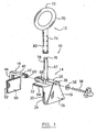
- a bath tub rail assembly according to one embodiment of the present invention is generally indicated by numeral 10 which includes a hand grip device 12 and a clamping device 14.
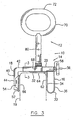
- the clamping device 14 generally includes a first clamping member 16 and a second clamping member 18 which are adjustable relative to each other for clamping opposite sides of a bath tub sidewall which is indicated by numeral 19 in Fig. 3 .
- the first clamping member 16 for example, includes a joining body such as a metal bar 20.
- the metal bar 20 may include a top wall 22 and opposite sidewalls 24, 26 to define a substantially rectangular or square hollow cross-sectional configuration having an open channel 28 extending between opposite open ends and along the entire length of the metal bar 20.
- a plate member 30 may be attached to the metal bar 20.
- the plate member 30 includes, for example, a top section 32 extending substantially in a horizontal direction to be positioned on the top of the bath tub sidewall 19.
- the plate member 30 further includes a clamping section 34 extending downwardly from one side edge of the top section 32 in a substantially vertical direction for abutting one side of the bath tub sidewall 19, and a connecting section 36 (may be shaped in a triangular shape) substantially parallel to the clamping section 34 and joined with a low end of the clamping section 34 in a U-shaped configuration (not indicated).
- the top section 32, clamping section 34 and connecting section 36 may be made by individual plates being welded together to form the plate member 30, or may be made integrally of a single metal plate in a bending and pressing process.
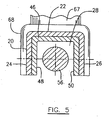
- the plate member 30 is attached to the joining body (metal bar 20) by, for example, welding one end of the metal bar 20 to an upper part of the connecting section 36 and welding the opposite sidewalls 24, 26 of the metal bar 20 (see Fig. 5 ) at the low edges thereof, to a top surface of the top section 32, thereby forming a rigid configuration of the first clamping member 16.
- An opening 38 is provided at a top portion of the connecting section 36 of the plate member 30, aligning with the channel 28 of the metal bar 20.
- the second clamping member 18 includes, for example, a joining body such as a metal bar 40 in an L-shape including a substantially horizontal arm 42 and a downwardly extending arm 44.
- the metal bar 40 has a hollow configuration similar to that of metal bar 20 but in a smaller size (see Fig. 5 ), including opposite sidewalls 48, 50 connected together by a middle wall 46, thereby defining a rectangular or square hollow cross-sectional configuration having an open channel (not indicated), to be slideably received in the channel 28 of the metal bar 20.
- a clamping plate 52 which may be made of a metal plate, is attached to the downwardly extending arm 44 of the metal bar 40, for example by welding, for abutting the other side of the bath tub sidewall 19.
- Reinforcement brackets 54 may be welded to the clamping plate 52 and the downwardly extending arm 44 to strengthen the attachment of the clamping plate 52 to the joining body (the metal bar 40).
- a set of a bolt 56, a washer 58 and a nut 60 are provided for adjusting a space between the clamping section 34 of the first clamping member 16 and the clamping plate 52 of the second clamping member 18.
- the nut 60 is attached, for example by welding, to an open end of the substantially horizontal arm 42 of the metal bar 40 for operatively receiving the bolt 56 which extends through the washer 58, the opening 38 in the connecting section 36 of the plate member 30, then through the channel 28 of the metal bar 20 (see Fig. 5 ) and through the nut 60, and may further extend into the inside of the hollow configuration (the open channel not indicated) of the substantially horizontal arm 42 of the metal bar 40.
- resilient pads such as rubber pads 62, 64 and 66 may be attached to a surface of the respective clamping section 34, top section 32 of the plate member 30 and clamping plate 52, which abut or contact the bath tub sidewall 19.
- a connecting tube which may be a cylindrical metal tube 67 is attached, for example by welding, to the metal bar 20 of the first clamping member 16 and extends upwardly therefrom.
- the cylindrical metal tube 67 may have an enlarged low end portion 68 which has a diameter greater than the width of the metal bar 20.
- a portion of the cylindrical wall at respectively diametrically opposite sides of the enlarged low end portion 68, is cut away to allow the metal bar 20 to extend through the enlarged low end portion 68, in a direction traverse to that of the cylindrical metal tube 67.
- Welding is applied between the cut edges of the enlarged low end portion 68 of the cylindrical metal tube 67 and the metal bar 20 to strengthen the attachment of the cylindrical metal tube 67 to the first clamping member 16.
- the hand grip device 12 of the bath tub rail assembly 10 generally includes a hand grip, for example, a metal grip ring 70 standing in a substantially upright position.
- the grip ring 70 may be optionally configured in an elliptical shape to define at least a substantially horizontal section 72 to be comfortably gripped by a user's hand.
- Another connecting tube, for example a cylindrical metal tube 74 is attached at its upper end by, for example, welding to a low section of the upright standing grip ring 70.
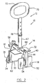
- the cylindrical metal tube 67 connected to the clamping device 14 through the first clamping member 16 and the cylindrical metal tube 74 connected to the grip ring 70, are slidably connected to form an adjustable connector between the hand grip device 12 and the clamping device 14 to allow a position of the grip ring 70 to be adjusted in both height and angular orientation relative to the bath tub side wall to which the bath tub rail assembly 10 is attached.
- the cylindrical tube 74 may be an outer tube and have an inner diameter greater than an outer diameter of the cylindrical tube 67 (an inner tube) such that the cylindrical tube 67 may be slidably inserted through an open low end into the cylindrical tube 74.
- a lock device for example, a spring biased lock pin device 76 may be attached within the cylindrical tube 67 (the inner tube) from the top end thereof.
- At least one lock pin 78 under a spring force, projects radially outwardly from a small hole (not indicated) defined in the cylindrical tube 67.
- a pair of lock pins 78 project in diametrically opposite directions from the cylindrical tube 67.
- the lock pin 78 can be pressed into the cylindrical wall of the cylindrical tube 67 by the cylindrical wall of the cylindrical tube 74 (the outer tube) when the cylindrical tube 67 (the inner tube) slides into and/or rotates within the cylindrical tube 74 (the outer tube).
- the spring biased lock pin device 76 is well known in the art and will not be further described herein.
- a plurality of positioning holes 80 may be defined in the cylindrical wall of the outer tube (cylindrical tube 74), which are distributed in different heights relative to the angular orientation of the low end of the tube and in different angular positions relative to the angular orientation of the grip ring 70.
- the positioning holes 80 may be defined in at least two columns (not indicated), and the two columns of the holes 80 may be spaced apart substantially by a quarter of the circumference of the cylindrical tube 74. Therefore, when at least one lock pin 78 engages a positioning hole 80 selected from either one of the columns, the grip ring 70 can be oriented in one of two angular positions substantially perpendicular to each other.
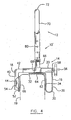
- one angular orientation of the grip ring 70 can be in a direction substantially transverse to the bath tub sidewall 19 as illustrated in Fig. 3 and the other angular orientation of the grip ring 70 can be substantially in the same direction as the bath tub sidewall 19, as illustrated in Fig. 4 .
- the grip ring 70 can be locked in a different height position while maintaining the same angular orientation. It should be understood that the grip pin 70 can be adjusted in either height or angular orientation and can also be adjusted in both height and angular orientation.
- Positioning holes 80 may be defined in four columns circumferentially equally spaced apart in accordance with the two diametrically oppositely positioned lock pins 78, such that the two lock pins 78 will be engaged with two holes defined in the respective diametrically oppositely defined columns in order to increase the locking strength of the telescoping connection of the cylindrical tubes 67 and 74.
- the number of positioning holes in each column may be determined according to how many height levels of the grip ring 70 are desired. If more than two angular positions of the grip ring 70 are desired, this may be achieved either by adding more columns of the positioning holes 80 or add more lock pins 78 in different angular positions in the cylindrical tube 67. In the latter case, selecting one of differently angularly positioned lock pins 78 to engage with a same positioning hole 80 or a different positioning hole 80 but in the same column, will change the orientation of the grip ring 70.
- a combination of selective lock pins and selective columns of positioning holes may provide more selective angular positions of the hand grip.
- Fig. 4 illustrates another embodiment of the present invention in which a bath tub rail assembly 10' is substantially similar to the bath tub rail assembly 10 illustrated in Figs. 1-3 . Therefore, like components are indicated by similar numerals and will not be redundantly described herein. Only the difference between the two embodiments is described below.
- the plate member 30 of the bath tub rail assembly 10' in Fig. 4 is attached only at the upper part of the connecting section 36 to the end of the metal bar 20.
- the top section 32 of the plate member 30 in the bath tub rail assembly 10' is not attached to the metal bar 20 and therefore, becomes a free end portion of the plate member 30.
- the U-shaped configuration between the clamping section 34 and the connecting section 36 acts as a spring to provide a resilient force therebetween when the bolt 56 is tightened to compress the first and second clamping members 16 and 18 against the opposite sides of the bath tub sidewall 19.
- the U-shaped configuration of the first clamping member 16 with a free end is less strong and rigid than the first clamping member 16 of the bath tub rail assembly 10 of Fig. 3 which has both ends attached to the metal bar 20. Nevertheless, the resiliency provided by the U-shaped configuration of the plate member 30 in the bath tub rail assembly 10' provides a more stable self-locking condition for the clamping device 14. It should be noted that the material of the plate member 30 and the proper dimensions thereof should be selected to provide an appropriate resiliency between the clamping section 34 and the connecting section 36 in order to avoid the clamping device 14 becoming too soft to achieve a secure attachment onto the bath tub sidewall 19.
- the materials used for the bath tub rail assembly may be metal materials such as steel tubes, plates but may also be of other materials having similar mechanical properties suitable for this application.
- the hand grip may be configured other than a grip ring, such as a hand grip bar, etc.
- the joining bodies of the clamping device may be configured differently from the metal bars described in the above embodiments.
Landscapes
- Health & Medical Sciences (AREA)
- Public Health (AREA)
- Epidemiology (AREA)
- General Health & Medical Sciences (AREA)
- Devices For Medical Bathing And Washing (AREA)
Claims (10)
- Badewannengeländeranordnung (10; 10') zur Verwendung an einer Badewannenseitenwand (19) mit einem Handgriff (12),
einer Klemmvorrichtung (14),
einem verstellbaren Verbinder zum Verbinden des Handgriffs (12) mit der Klemmvorrichtung (14), damit eine Position des Handgriffs (12) sowohl höhenmäßig als auch in der winkelförmigen Ausrichtung zu der Badewannenseitenwand (19) verstellt werden kann, und
einer Schlossvorrichtung (76) zum Verriegeln des Handgriffs (12) sowohl in einer gewählten Höhenposition als auch in einer gewählten winkelförmigen Ausrichtung,
wobei der verstellbare Verbinder eine teleskopartige Konfiguration mit einer ersten Röhre (74), die am Handgriff (12) oder an der Klemmvorrichtung (14) befestigt ist, und einer zweiten Röhre (67), die an der Klemmvorrichtung (14) oder am Handgriff (12) befestigt ist, umfasst, wobei die erste und die zweite Röhre (74, 67) zylindrisch sind und ein Innendurchmesser der ersten Röhre (74) größer als ein Außendurchmesser der zweiten Röhre (67) ist,
dadurch gekennzeichnet, dass
die Klemmvorrichtung ein erstes und ein zweites Klemmelement (16, 18) hat, die zum Klemmen gegenüberliegender Seiten der Badewannenseitenwand (19), um die Badewannengeländeranordnung (10; 10') an der Badewannenseitenwand (19) zu befestigen, zueinander verstellbar sind, und
die Badewannengeländeranordnung mehrere Löcher (80) durch eine Röhrenwand der ersten Röhre (74) definiert, wobei die zweite Röhre (67) ein Schlosselement (78) aufweist, das gezielt in den jeweiligen Löchern (80) der ersten Röhre (74) in Eingriff zu nehmen ist, wobei die Löcher (80) mindestens in zwei Spalten definiert sind, wobei die beiden Spalten der Löcher (80) im Wesentlichen um ein Viertel eines Umfangs der ersten Röhre (74) beabstandet sind. - Badewannengeländeranordnung nach Anspruch 1, wobei der Handgriff (12) einen Abschnitt (72) davon umfasst, der sich in einer im Wesentlichen horizontalen Richtung erstreckt.
- Badewannengeländeranordnung nach Anspruch 1 oder 2, wobei der Handgriff (12) einen Griffring (70) umfasst.
- Badewannengeländeranordnung nach Anspruch 1, 2 oder 3, wobei der Handgriff (12) einen im wesentlichen horizontalen Abschnitt (72) umfasst, der sich gezielt in einer ersten winkelförmigen Ausrichtung, die im Wesentlichen parallel zur Badewannenseitenwand (19) verläuft, oder in einer zweiten winkelförmigen Ausrichtung, die im Wesentlichen senkrecht zur Badewannenseitenwand (19) verläuft, erstreckt.
- Badewannengeländeranordnung nach einem der vorhergehenden Ansprüche, wobei das erste und das zweite Klemmelement (16, 18) jeweils einen ersten und einen zweiten Verbindungskörper (20, 40) umfassen, an denen jeweils eine erste und eine zweite sich nach unten erstreckende Platte (30, 52) angebracht sind, wobei der erste oder der zweite verbindungskörper (20, 40) mit dem verstellbaren Verbinder verbunden ist und der erste und der zweite Verbindungskörper (20, 40) verstellbar miteinander verbunden sind, um einen Abstand zwischen der ersten und der zweiten Platte (30, 52) zu verstellen.
- Badewannengeländeranordnung nach Anspruch 5, wobei das erste Klemmelement eine Konfiguration umfasst, die die erste Platte (30) federnd mit dem ersten Verbindungskörper (20) verbindet, damit eine federnde Kraft zwischen der ersten Platte (30) und dem ersten Verbindungskörper (20) aufgebracht werden kann.
- Badewannengeländeranordnung nach Anspruch 3, wobei der verstellbare Verbinder und die Schlossvorrichtung kombiniert ein Paar verbundener innerer und äußerer Röhren (67, 74) umfassen, die zueinander verschiebbar sind und jeweils am Griffring (70) und am ersten Klemmelement befestigt sind, wobei die äußere Röhre (74) mehrere Löcher (80) mindestens in zwei Spalten definiert und die innere Röhre (67) einen Schlossstift (78) aufweist, der gezielt in einem der Löcher (80) in einer der Spalten der äußeren Röhre (74) in Eingriff zu nehmen ist, wodurch eine sichere Positionierung des Griffrings des Handgriffs (12) sowohl in einer gewählten Höhe als auch in einer gewählten winkelförmigen Ausrichtung bezüglich der Badewannenseitenwand (19) gestattet ist.
- Badewannengeländeranordnung nach Anspruch 7, wobei das erste Klemmelement (16) einen ersten verbindungskörper (20), der an der äußeren oder der inneren Röhre (67) befestigt ist, und ein Plattenelement (30) umfasst, das am ersten verbindungskörper (20) angebracht ist und einen oberen Abschnitt (32), der geeignet ist, auf eine Oberseite der Badewannenseitenwand (19) positioniert zu werden, einen Klemmabschnitt (34), der sich von einem Seitenrand des oberen Abschnitts (32) nach unten erstreckt, um an einer Seite der Badewannenseitenwand (19) abzustoßen, und einen Verbindungsabschnitt (36) aufweist, der mit einem unteren Ende des Klemmabschnitts (34) in einer U-förmigen Konfiguration verbunden ist und sich im Wesentlichen aufrecht erstreckt, wobei der Verbindungsabschnitt (36) an einem oberen Teil des ersten verbindungskörpers (20) befestigt ist, wobei das zweite Klemmelement (18) einen zweiten Verbindungskörper (40) und eine Klemmplatte (52) aufweist, die am zweiten Verbindungskörper (40) angebracht ist, um an der anderen Seite der Badewannenseitenwand (19) anzustoßen, wobei der zweite verbindungskörper (40) verstellbar mit dem ersten Verbindungskörper (20) des ersten Klemmelements (16) verbunden ist, um einen Abstand zwischen der Klemmplatte (52) des zweiten Klemmelements (18) und dem Klemmabschnitt (34) des ersten Klemmelements (16) zu verstellen.
- Badewannengeländeranordnung nach Anspruch 8, wobei der obere Abschnitt (32) des Plattenelements (30) am ersten Verbindungskörper (20) des ersten Klemmelements (16) befestigt ist.
- Badewannengeländeranordnung nach Anspruch 8 oder 9, wobei der erste und der zweite Verbindungskörper (20, 40) eine hohle Konfiguration umfassen, damit der zweite Verbindungskörper (40) in den ersten Verbindungskörper (20) eingeführt werden kann und sich ein Verbindungsbolzen (56) durch den ersten Verbindungskörper (20) in den zweiten Verbindungskörper (40) erstrecken kann, wodurch eine Gleitbewegung zwischen dem ersten und dem zweiten Verbindungskörper (20, 40) veranlasst wird, wodurch die Badewannenseitenwand (19) mit einer Klemmkraft beaufschlagt wird.
Priority Applications (1)
| Application Number | Priority Date | Filing Date | Title |
|---|---|---|---|
| EP20080250727 EP2098147B1 (de) | 2008-03-03 | 2008-03-03 | Badewannengeländer |
Applications Claiming Priority (1)
| Application Number | Priority Date | Filing Date | Title |
|---|---|---|---|
| EP20080250727 EP2098147B1 (de) | 2008-03-03 | 2008-03-03 | Badewannengeländer |
Publications (2)
| Publication Number | Publication Date |
|---|---|
| EP2098147A1 EP2098147A1 (de) | 2009-09-09 |
| EP2098147B1 true EP2098147B1 (de) | 2012-08-08 |
Family
ID=39523681
Family Applications (1)
| Application Number | Title | Priority Date | Filing Date |
|---|---|---|---|
| EP20080250727 Not-in-force EP2098147B1 (de) | 2008-03-03 | 2008-03-03 | Badewannengeländer |
Country Status (1)
| Country | Link |
|---|---|
| EP (1) | EP2098147B1 (de) |
Family Cites Families (5)
| Publication number | Priority date | Publication date | Assignee | Title |
|---|---|---|---|---|
| DE8522957U1 (de) * | 1985-08-09 | 1985-09-26 | Gebrüder Schulte GmbH & Co KG, 5768 Sundern | An einer Badewanne anklemmbarer Haltegriff |
| CA2148521C (en) | 1995-05-03 | 2002-05-21 | John L. O'Brien | A support pole with pivoting and locking handrail for elderly and disabled persons |
| US6332230B1 (en) * | 2001-04-10 | 2001-12-25 | Shih-Kuo Chang | Tub grab bar structure |
| DE20306743U1 (de) | 2003-04-30 | 2003-09-04 | Chang, Shih-Kuo, Tainan | Badewannenhaltegriff |
| US7203978B1 (en) | 2006-05-26 | 2007-04-17 | Shih-Kuo Chang | Swivel handle structure for a bathtub |
-
2008
- 2008-03-03 EP EP20080250727 patent/EP2098147B1/de not_active Not-in-force
Also Published As
| Publication number | Publication date |
|---|---|
| EP2098147A1 (de) | 2009-09-09 |
Similar Documents
| Publication | Publication Date | Title |
|---|---|---|
| US7823230B2 (en) | Bath tub rail | |
| US4417361A (en) | Grab bar | |
| US4475256A (en) | Shower transfer bench | |
| US9907723B2 (en) | Universal user assist seat for walkers | |
| US7823599B2 (en) | Flexible cane foot | |
| US5628335A (en) | Shock absorbing crutch | |
| EP1884400A2 (de) | Haltevorrichtung für einen Sicherheitskindersitz in einem Fahrzeug | |
| US3414910A (en) | Clamp-on grab rail for bathtubs or the like | |
| JPH0531681A (ja) | 調節自在な用具保持装置 | |
| US20080289296A1 (en) | Safety bar systems and methods | |
| US20090044380A1 (en) | Replaceable hand grip | |
| US10434028B2 (en) | Stairway step aid | |
| EP2450156A1 (de) | Faltbare Sägeböcke | |
| US8336835B1 (en) | Support device and method of use | |
| WO2000076809A1 (en) | Vehicle-mounted load carrier | |
| US5415371A (en) | Martial-arts breaking-board holder | |
| US6412741B1 (en) | Beverage holding device with railing attachment | |
| US5352057A (en) | Adjustment tool for telescoping members | |
| JP2013052208A (ja) | 浴槽用手すり | |
| EP1969983A2 (de) | Handlauf | |
| US5299589A (en) | Orthopedic crutch with adjustable hand grip | |
| US20070186348A1 (en) | Providing mobility support | |
| KR101875910B1 (ko) | 좌변기용 안전손잡이 | |
| US5971341A (en) | Adjustable leg system | |
| CA2622179C (en) | Bath tub rail |
Legal Events
| Date | Code | Title | Description |
|---|---|---|---|
| PUAI | Public reference made under article 153(3) epc to a published international application that has entered the european phase |
Free format text: ORIGINAL CODE: 0009012 |
|
| AK | Designated contracting states |
Kind code of ref document: A1 Designated state(s): AT BE BG CH CY CZ DE DK EE ES FI FR GB GR HR HU IE IS IT LI LT LU LV MC MT NL NO PL PT RO SE SI SK TR |
|
| AX | Request for extension of the european patent |
Extension state: AL BA MK RS |
|
| 17P | Request for examination filed |
Effective date: 20100128 |
|
| 17Q | First examination report despatched |
Effective date: 20100226 |
|
| AKX | Designation fees paid |
Designated state(s): AT BE BG CH CY CZ DE DK EE ES FI FR GB GR HR HU IE IS IT LI LT LU LV MC MT NL NO PL PT RO SE SI SK TR |
|
| GRAP | Despatch of communication of intention to grant a patent |
Free format text: ORIGINAL CODE: EPIDOSNIGR1 |
|
| GRAS | Grant fee paid |
Free format text: ORIGINAL CODE: EPIDOSNIGR3 |
|
| GRAA | (expected) grant |
Free format text: ORIGINAL CODE: 0009210 |
|
| AK | Designated contracting states |
Kind code of ref document: B1 Designated state(s): AT BE BG CH CY CZ DE DK EE ES FI FR GB GR HR HU IE IS IT LI LT LU LV MC MT NL NO PL PT RO SE SI SK TR |
|
| REG | Reference to a national code |
Ref country code: GB Ref legal event code: FG4D |
|
| REG | Reference to a national code |
Ref country code: CH Ref legal event code: EP Ref country code: AT Ref legal event code: REF Ref document number: 569279 Country of ref document: AT Kind code of ref document: T Effective date: 20120815 |
|
| REG | Reference to a national code |
Ref country code: IE Ref legal event code: FG4D |
|
| REG | Reference to a national code |
Ref country code: DE Ref legal event code: R096 Ref document number: 602008017771 Country of ref document: DE Effective date: 20121004 |
|
| REG | Reference to a national code |
Ref country code: NL Ref legal event code: T3 |
|
| REG | Reference to a national code |
Ref country code: AT Ref legal event code: MK05 Ref document number: 569279 Country of ref document: AT Kind code of ref document: T Effective date: 20120808 |
|
| REG | Reference to a national code |
Ref country code: LT Ref legal event code: MG4D Effective date: 20120808 |
|
| PG25 | Lapsed in a contracting state [announced via postgrant information from national office to epo] |
Ref country code: NO Free format text: LAPSE BECAUSE OF FAILURE TO SUBMIT A TRANSLATION OF THE DESCRIPTION OR TO PAY THE FEE WITHIN THE PRESCRIBED TIME-LIMIT Effective date: 20121108 Ref country code: CY Free format text: LAPSE BECAUSE OF FAILURE TO SUBMIT A TRANSLATION OF THE DESCRIPTION OR TO PAY THE FEE WITHIN THE PRESCRIBED TIME-LIMIT Effective date: 20120808 Ref country code: HR Free format text: LAPSE BECAUSE OF FAILURE TO SUBMIT A TRANSLATION OF THE DESCRIPTION OR TO PAY THE FEE WITHIN THE PRESCRIBED TIME-LIMIT Effective date: 20120808 Ref country code: IS Free format text: LAPSE BECAUSE OF FAILURE TO SUBMIT A TRANSLATION OF THE DESCRIPTION OR TO PAY THE FEE WITHIN THE PRESCRIBED TIME-LIMIT Effective date: 20121208 Ref country code: FI Free format text: LAPSE BECAUSE OF FAILURE TO SUBMIT A TRANSLATION OF THE DESCRIPTION OR TO PAY THE FEE WITHIN THE PRESCRIBED TIME-LIMIT Effective date: 20120808 Ref country code: AT Free format text: LAPSE BECAUSE OF FAILURE TO SUBMIT A TRANSLATION OF THE DESCRIPTION OR TO PAY THE FEE WITHIN THE PRESCRIBED TIME-LIMIT Effective date: 20120808 Ref country code: LT Free format text: LAPSE BECAUSE OF FAILURE TO SUBMIT A TRANSLATION OF THE DESCRIPTION OR TO PAY THE FEE WITHIN THE PRESCRIBED TIME-LIMIT Effective date: 20120808 |
|
| PG25 | Lapsed in a contracting state [announced via postgrant information from national office to epo] |
Ref country code: LV Free format text: LAPSE BECAUSE OF FAILURE TO SUBMIT A TRANSLATION OF THE DESCRIPTION OR TO PAY THE FEE WITHIN THE PRESCRIBED TIME-LIMIT Effective date: 20120808 Ref country code: SI Free format text: LAPSE BECAUSE OF FAILURE TO SUBMIT A TRANSLATION OF THE DESCRIPTION OR TO PAY THE FEE WITHIN THE PRESCRIBED TIME-LIMIT Effective date: 20120808 Ref country code: PL Free format text: LAPSE BECAUSE OF FAILURE TO SUBMIT A TRANSLATION OF THE DESCRIPTION OR TO PAY THE FEE WITHIN THE PRESCRIBED TIME-LIMIT Effective date: 20120808 Ref country code: BE Free format text: LAPSE BECAUSE OF FAILURE TO SUBMIT A TRANSLATION OF THE DESCRIPTION OR TO PAY THE FEE WITHIN THE PRESCRIBED TIME-LIMIT Effective date: 20120808 Ref country code: PT Free format text: LAPSE BECAUSE OF FAILURE TO SUBMIT A TRANSLATION OF THE DESCRIPTION OR TO PAY THE FEE WITHIN THE PRESCRIBED TIME-LIMIT Effective date: 20121210 Ref country code: SE Free format text: LAPSE BECAUSE OF FAILURE TO SUBMIT A TRANSLATION OF THE DESCRIPTION OR TO PAY THE FEE WITHIN THE PRESCRIBED TIME-LIMIT Effective date: 20120808 Ref country code: GR Free format text: LAPSE BECAUSE OF FAILURE TO SUBMIT A TRANSLATION OF THE DESCRIPTION OR TO PAY THE FEE WITHIN THE PRESCRIBED TIME-LIMIT Effective date: 20121109 |
|
| PG25 | Lapsed in a contracting state [announced via postgrant information from national office to epo] |
Ref country code: ES Free format text: LAPSE BECAUSE OF FAILURE TO SUBMIT A TRANSLATION OF THE DESCRIPTION OR TO PAY THE FEE WITHIN THE PRESCRIBED TIME-LIMIT Effective date: 20121119 Ref country code: CZ Free format text: LAPSE BECAUSE OF FAILURE TO SUBMIT A TRANSLATION OF THE DESCRIPTION OR TO PAY THE FEE WITHIN THE PRESCRIBED TIME-LIMIT Effective date: 20120808 Ref country code: RO Free format text: LAPSE BECAUSE OF FAILURE TO SUBMIT A TRANSLATION OF THE DESCRIPTION OR TO PAY THE FEE WITHIN THE PRESCRIBED TIME-LIMIT Effective date: 20120808 Ref country code: DK Free format text: LAPSE BECAUSE OF FAILURE TO SUBMIT A TRANSLATION OF THE DESCRIPTION OR TO PAY THE FEE WITHIN THE PRESCRIBED TIME-LIMIT Effective date: 20120808 Ref country code: EE Free format text: LAPSE BECAUSE OF FAILURE TO SUBMIT A TRANSLATION OF THE DESCRIPTION OR TO PAY THE FEE WITHIN THE PRESCRIBED TIME-LIMIT Effective date: 20120808 |
|
| PG25 | Lapsed in a contracting state [announced via postgrant information from national office to epo] |
Ref country code: IT Free format text: LAPSE BECAUSE OF FAILURE TO SUBMIT A TRANSLATION OF THE DESCRIPTION OR TO PAY THE FEE WITHIN THE PRESCRIBED TIME-LIMIT Effective date: 20120808 Ref country code: SK Free format text: LAPSE BECAUSE OF FAILURE TO SUBMIT A TRANSLATION OF THE DESCRIPTION OR TO PAY THE FEE WITHIN THE PRESCRIBED TIME-LIMIT Effective date: 20120808 |
|
| PLBE | No opposition filed within time limit |
Free format text: ORIGINAL CODE: 0009261 |
|
| STAA | Information on the status of an ep patent application or granted ep patent |
Free format text: STATUS: NO OPPOSITION FILED WITHIN TIME LIMIT |
|
| 26N | No opposition filed |
Effective date: 20130510 |
|
| PG25 | Lapsed in a contracting state [announced via postgrant information from national office to epo] |
Ref country code: BG Free format text: LAPSE BECAUSE OF FAILURE TO SUBMIT A TRANSLATION OF THE DESCRIPTION OR TO PAY THE FEE WITHIN THE PRESCRIBED TIME-LIMIT Effective date: 20121108 |
|
| REG | Reference to a national code |
Ref country code: DE Ref legal event code: R097 Ref document number: 602008017771 Country of ref document: DE Effective date: 20130510 |
|
| PG25 | Lapsed in a contracting state [announced via postgrant information from national office to epo] |
Ref country code: MC Free format text: LAPSE BECAUSE OF NON-PAYMENT OF DUE FEES Effective date: 20130331 |
|
| REG | Reference to a national code |
Ref country code: CH Ref legal event code: PL |
|
| REG | Reference to a national code |
Ref country code: IE Ref legal event code: MM4A |
|
| PG25 | Lapsed in a contracting state [announced via postgrant information from national office to epo] |
Ref country code: CH Free format text: LAPSE BECAUSE OF NON-PAYMENT OF DUE FEES Effective date: 20130331 Ref country code: IE Free format text: LAPSE BECAUSE OF NON-PAYMENT OF DUE FEES Effective date: 20130303 Ref country code: LI Free format text: LAPSE BECAUSE OF NON-PAYMENT OF DUE FEES Effective date: 20130331 |
|
| PG25 | Lapsed in a contracting state [announced via postgrant information from national office to epo] |
Ref country code: MT Free format text: LAPSE BECAUSE OF FAILURE TO SUBMIT A TRANSLATION OF THE DESCRIPTION OR TO PAY THE FEE WITHIN THE PRESCRIBED TIME-LIMIT Effective date: 20120808 |
|
| PG25 | Lapsed in a contracting state [announced via postgrant information from national office to epo] |
Ref country code: TR Free format text: LAPSE BECAUSE OF FAILURE TO SUBMIT A TRANSLATION OF THE DESCRIPTION OR TO PAY THE FEE WITHIN THE PRESCRIBED TIME-LIMIT Effective date: 20120808 |
|
| PG25 | Lapsed in a contracting state [announced via postgrant information from national office to epo] |
Ref country code: LU Free format text: LAPSE BECAUSE OF NON-PAYMENT OF DUE FEES Effective date: 20130303 Ref country code: HU Free format text: LAPSE BECAUSE OF FAILURE TO SUBMIT A TRANSLATION OF THE DESCRIPTION OR TO PAY THE FEE WITHIN THE PRESCRIBED TIME-LIMIT; INVALID AB INITIO Effective date: 20080303 |
|
| REG | Reference to a national code |
Ref country code: FR Ref legal event code: PLFP Year of fee payment: 9 |
|
| REG | Reference to a national code |
Ref country code: DE Ref legal event code: R081 Ref document number: 602008017771 Country of ref document: DE Owner name: A.M.G. MEDICAL INC., CA Free format text: FORMER OWNER: AMG MEDICAL INC., MONTREAL, CA Ref country code: DE Ref legal event code: R082 Ref document number: 602008017771 Country of ref document: DE Representative=s name: DEHNS, GB |
|
| REG | Reference to a national code |
Ref country code: NL Ref legal event code: HC Owner name: A.M.G. MEDICAL INC.; CA Free format text: DETAILS ASSIGNMENT: CHANGE OF OWNER(S), CHANGE OF OWNER(S) NAME; FORMER OWNER NAME: AMG MEDICAL INC. Effective date: 20161222 |
|
| REG | Reference to a national code |
Ref country code: GB Ref legal event code: S117 Free format text: REQUEST FILED; REQUEST FOR CORRECTION UNDER SECTION 117 FILED ON 5 DECEMBER 2016 Ref country code: GB Ref legal event code: S117 Free format text: CORRECTIONS ALLOWED; REQUEST FOR CORRECTION UNDER SECTION 117 FILED ON 5 DECEMBER 2016 ALLOWED ON 23 JANUARY 2017 |
|
| REG | Reference to a national code |
Ref country code: FR Ref legal event code: PLFP Year of fee payment: 10 |
|
| PGFP | Annual fee paid to national office [announced via postgrant information from national office to epo] |
Ref country code: NL Payment date: 20170322 Year of fee payment: 10 Ref country code: FR Payment date: 20170323 Year of fee payment: 10 |
|
| PGFP | Annual fee paid to national office [announced via postgrant information from national office to epo] |
Ref country code: GB Payment date: 20170323 Year of fee payment: 10 |
|
| REG | Reference to a national code |
Ref country code: FR Ref legal event code: RM Effective date: 20170607 |
|
| PGFP | Annual fee paid to national office [announced via postgrant information from national office to epo] |
Ref country code: DE Payment date: 20170403 Year of fee payment: 10 |
|
| REG | Reference to a national code |
Ref country code: DE Ref legal event code: R119 Ref document number: 602008017771 Country of ref document: DE |
|
| REG | Reference to a national code |
Ref country code: NL Ref legal event code: MM Effective date: 20180401 |
|
| GBPC | Gb: european patent ceased through non-payment of renewal fee |
Effective date: 20180303 |
|
| PG25 | Lapsed in a contracting state [announced via postgrant information from national office to epo] |
Ref country code: NL Free format text: LAPSE BECAUSE OF NON-PAYMENT OF DUE FEES Effective date: 20180401 |
|
| PG25 | Lapsed in a contracting state [announced via postgrant information from national office to epo] |
Ref country code: DE Free format text: LAPSE BECAUSE OF NON-PAYMENT OF DUE FEES Effective date: 20181002 |
|
| PG25 | Lapsed in a contracting state [announced via postgrant information from national office to epo] |
Ref country code: GB Free format text: LAPSE BECAUSE OF NON-PAYMENT OF DUE FEES Effective date: 20180303 |
|
| PG25 | Lapsed in a contracting state [announced via postgrant information from national office to epo] |
Ref country code: FR Free format text: LAPSE BECAUSE OF NON-PAYMENT OF DUE FEES Effective date: 20180331 |