EP2096714B1 - Electrical connection device with contact spring operated by a lever having an inlet opening for the end of an electric cable - Google Patents
Electrical connection device with contact spring operated by a lever having an inlet opening for the end of an electric cable Download PDFInfo
- Publication number
- EP2096714B1 EP2096714B1 EP08425054A EP08425054A EP2096714B1 EP 2096714 B1 EP2096714 B1 EP 2096714B1 EP 08425054 A EP08425054 A EP 08425054A EP 08425054 A EP08425054 A EP 08425054A EP 2096714 B1 EP2096714 B1 EP 2096714B1
- Authority
- EP
- European Patent Office
- Prior art keywords
- lever
- case
- contact
- spring
- contact element
- Prior art date
- Legal status (The legal status is an assumption and is not a legal conclusion. Google has not performed a legal analysis and makes no representation as to the accuracy of the status listed.)
- Not-in-force
Links
- 238000003780 insertion Methods 0.000 claims abstract description 9
- 230000037431 insertion Effects 0.000 claims abstract description 9
- 239000011810 insulating material Substances 0.000 claims description 6
- 239000002184 metal Substances 0.000 claims description 2
- 229910052751 metal Inorganic materials 0.000 claims description 2
- 230000005405 multipole Effects 0.000 description 4
- 210000002105 tongue Anatomy 0.000 description 4
- 229910000831 Steel Inorganic materials 0.000 description 2
- 238000005304 joining Methods 0.000 description 2
- 238000003825 pressing Methods 0.000 description 2
- 239000010959 steel Substances 0.000 description 2
- RYGMFSIKBFXOCR-UHFFFAOYSA-N Copper Chemical compound [Cu] RYGMFSIKBFXOCR-UHFFFAOYSA-N 0.000 description 1
- 229910000881 Cu alloy Inorganic materials 0.000 description 1
- 230000003321 amplification Effects 0.000 description 1
- 239000002131 composite material Substances 0.000 description 1
- 239000004020 conductor Substances 0.000 description 1
- 229910052802 copper Inorganic materials 0.000 description 1
- 239000010949 copper Substances 0.000 description 1
- 238000002788 crimping Methods 0.000 description 1
- 238000000605 extraction Methods 0.000 description 1
- 238000004519 manufacturing process Methods 0.000 description 1
- 239000007769 metal material Substances 0.000 description 1
- 238000000034 method Methods 0.000 description 1
- 238000000465 moulding Methods 0.000 description 1
- 230000007935 neutral effect Effects 0.000 description 1
- 238000003199 nucleic acid amplification method Methods 0.000 description 1
- 238000005476 soldering Methods 0.000 description 1
Images


Classifications
-
- H—ELECTRICITY
- H01—ELECTRIC ELEMENTS
- H01R—ELECTRICALLY-CONDUCTIVE CONNECTIONS; STRUCTURAL ASSOCIATIONS OF A PLURALITY OF MUTUALLY-INSULATED ELECTRICAL CONNECTING ELEMENTS; COUPLING DEVICES; CURRENT COLLECTORS
- H01R4/00—Electrically-conductive connections between two or more conductive members in direct contact, i.e. touching one another; Means for effecting or maintaining such contact; Electrically-conductive connections having two or more spaced connecting locations for conductors and using contact members penetrating insulation
- H01R4/28—Clamped connections, spring connections
- H01R4/48—Clamped connections, spring connections utilising a spring, clip, or other resilient member
- H01R4/4809—Clamped connections, spring connections utilising a spring, clip, or other resilient member using a leaf spring to bias the conductor toward the busbar
- H01R4/4828—Spring-activating arrangements mounted on or integrally formed with the spring housing
- H01R4/48365—Spring-activating arrangements mounted on or integrally formed with the spring housing with integral release means
-
- H—ELECTRICITY
- H01—ELECTRIC ELEMENTS
- H01R—ELECTRICALLY-CONDUCTIVE CONNECTIONS; STRUCTURAL ASSOCIATIONS OF A PLURALITY OF MUTUALLY-INSULATED ELECTRICAL CONNECTING ELEMENTS; COUPLING DEVICES; CURRENT COLLECTORS
- H01R4/00—Electrically-conductive connections between two or more conductive members in direct contact, i.e. touching one another; Means for effecting or maintaining such contact; Electrically-conductive connections having two or more spaced connecting locations for conductors and using contact members penetrating insulation
- H01R4/28—Clamped connections, spring connections
- H01R4/48—Clamped connections, spring connections utilising a spring, clip, or other resilient member
- H01R4/4809—Clamped connections, spring connections utilising a spring, clip, or other resilient member using a leaf spring to bias the conductor toward the busbar
- H01R4/48455—Clamped connections, spring connections utilising a spring, clip, or other resilient member using a leaf spring to bias the conductor toward the busbar insertion of a wire only possible by pressing on the spring
-
- H—ELECTRICITY
- H01—ELECTRIC ELEMENTS
- H01R—ELECTRICALLY-CONDUCTIVE CONNECTIONS; STRUCTURAL ASSOCIATIONS OF A PLURALITY OF MUTUALLY-INSULATED ELECTRICAL CONNECTING ELEMENTS; COUPLING DEVICES; CURRENT COLLECTORS
- H01R9/00—Structural associations of a plurality of mutually-insulated electrical connecting elements, e.g. terminal strips or terminal blocks; Terminals or binding posts mounted upon a base or in a case; Bases therefor
- H01R9/22—Bases, e.g. strip, block, panel
- H01R9/24—Terminal blocks
- H01R9/26—Clip-on terminal blocks for side-by-side rail- or strip-mounting
Definitions
- the present invention relates to an electrical connection device with a contact spring operated by a lever having an inlet opening for the end of an electric cable.
- Electrical connection devices are known where a spring ensures electrical contact between a conducting element, which acts as an electrical contact grip or pin, and the end of an electric cable.
- the function of the spring is to press the end of the cable against the conducting element, ensuring a minimum contact resistance.
- the contact spring which is usually a leaf spring, suitably folded, is actuated by a mechanical means, lever, cam or wedge, so as to open a space which allows the introduction of the end of an electric cable between the spring and the conducting element or, on the other hand, extraction, without force, of an end which has previously been inserted.
- the contact spring is actuated by a cam which extends in the form of an actuating lever and is hinged with a case made of insulating material and housing the conducting element and the spring.
- An opening in the case allows the end of the cable to be introduced inside the case and positioned when the lever is operated, between the contact spring and the conducting element.
- the actuating lever is conveniently shaped so as to engage with one end of a screwdriver which increases the lever arm.
- the sliding piece acts on the spring in the manner of a wedge which flexes the spring so as to form the space for insertion of the cable end and, in this case it is the pushbutton which has an inlet and guiding opening for the cable end.
- the head of which is practically occupied entirely by the inlet opening, it is necessary to use a tool, such as a screw driver, in order to exert a suitable thrusting force on it.
- the wedge system is prone to jamming, the smaller the taper angle of the wedge, and does not offer the same guarantee of reliability as a lever system, where the lever is able to assume its rest position again without substantial friction.
- a further drawback of these solutions is that the contact spring acts on the end of the cable with its sharp edge and exerts on the latter a localised force which does not ensure an adequate contact surface area between the cable end and the contact element.
- the present invention aims to overcome these drawbacks and proposes a connection device which is particularly compact, functionally efficient and reliable and suitable for the most varied uses, in particular for forming multi-pole electric connectors.
- connection device as characterized by the claims.
- the electrical contact device consists of two half-shells 1, 2 which are made of insulating material and each have two parallel sides 3, 4 and 5,6, respectively, which are equally spaced, and an end wall 7, 8, respectively.
- the two axially aligned openings have a slight undercut on the outer side of the two half-shells.
- a contact element 13 made of metallic material which is a good conductor (copper or copper alloy) and a folded-leaf contact spring 14 are housed inside the two half-shells.
- the contact element 13 is kept in position, inside the two half-shells, by suitable raised ribs which are formed inside the two half-shells and are collectively identified by the reference number 15.
- a lever 16 made of insulating material and with a pair of axially aligned pins 17,18 which are inserted in the openings 11,12 of the two half-shells, closes the side of the two half-shells opposite to the end walls 7,8 and is partly housed inside the two half-shells.
- the pins 17,18 have, at their ends, a slight toroidal relief which, when the pins are forced into the openings 11,12, engages in the undercut of said openings and forms a snap-engaging connection between the two half-shells, while allowing rotation of the lever relative to the two half-shells.
- the snap-engagement connection between the two half-shells is completed by two teeth, one of which 19 is visible, said teeth being respectively arranged in a recess 20,21 formed in the side 6 and in the end wall of the half-shell 2, respectively.
- the two half-shells 1 and 2 instead of being snap-engaged together, may be heat-bonded together, but a snap-engaging connection is preferred because it simplifies the production process.
- the engaging teeth and the associated eyelets may be obtained during the process which involves moulding of the half-shells in a mould and counter-mould, without requiring the use of composite moulds.
- a tooth 26 extending longitudinally over a certain length of the side is formed as a relief on the sides 3 and 5.
- the two teeth arranged on top of each other form an engaging tooth with a dovetail cross-section which is used to engage slidably the case of the contact device inside an external support ( Figure 6 ) provided with a plurality of insertion recesses, each of which is able to receive an engaging member.
- At least one of the sides 3,5 extends beyond the end wall 7,8 in the form of a resilient elastic tongue 28 terminating in an engaging tooth 30 co-operating with a stop member of the external support.
- the lever 16 has, arranged between its end hinged on the half-shells and its free end 23, suitably shaped and knurled to ensure a sufficient pressing area, an eyelet opening 24 which allows the introduction of a cable end inside the case formed by the two half-shells 1 and 2 joined together.
- the walls of the opening 24, which are suitably tapered to form a guide for directing the end of the cable, extend inside the two half-shells.
- the wall 25 of the opening 24 closest to the pins 17,18 and the adjacent sides of the opening perform the function of a thrusting part which, when the lever 16 is operated (by exerting a suitable pressure on its end portion and causing, with reference to the figure, a slight rotation thereof in the anti-clockwise direction) interferes with the contact spring 14, deforming it.
- the contact element 13 has a flat contact side 31 perpendicular to which an eyelet 32 extends.
- the contact element In the opposite direction to that of the eyelet 32, the contact element, suitably folded, extends in the form of two superimposed blades 33,34 which form a contact grip, for example for electrical connection to a conducting bar.
- the contact grip protrudes from the case formed by the two half-shells 1 and 2 through an opening formed by two undercuts 35,36 formed in the sides 4 and 6.
- a metal rider 37 made of music steel is mounted on the grip, inside the case, as indicated by the arrows 38,39.
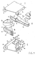
- the blades 33,34 may be replaced by a single contact blade 40, as shown in Figure 5 .
- the contact blade 40 is connected to the flat side 31 of the contact element by an elongated portion 29 which is folded in a U shape and provides the blade with a certain elasticity in the axial direction of the blade.
- a contact spring 55 which is similar or identical to the spring 14 ( Fig. 1 ), may be inserted in the saddle 29, as indicated by the arrow 56.
- the blades 33,34 may be replaced by two short tongues 41,42 which are suitably folded in order to grip permanently an end 43 of an electric cable 27, by means of crimping, as shown in Figure 4 .
- permanent fixing of the cable end may be performed by means of soldering.
- these walls have suitable undercuts (only one of which 44 is visible) which are arranged next to each other and form said opening.
- the contact spring 14 consists of a tongue of music steel folded in a U shape with a flattened and tapered end 45 which is inserted in the eyelet 32 of the contact element 13 and presses against the flat side 31.
- the opposite end 46 of the contact spring which is also tapered and folded externally in the form of an L, is inserted in the eyelet 32 and arranged in contact with the rim 47 of the eyelet opposite the flat side 31.
- Figure 2 shows the arrangement of the various parts in the insulating case with the lever 16 and the spring 14 in the rest position.
- Figure 3 shows the arrangement of the various parts when the lever 16 is operated with a small rotation in an anti-clockwise direction and exerts a thrusting force, with its wall 25, against the portion 49 of the contact spring.
- the end 45 of the contact spring is spaced apart from the flat side 31 of the contact element and it is possible to insert, through the opening 24 of the actuating lever, a cable end 50 which is arranged freely and without force between the flat side 31 of the contact element and the end 45 of the contact spring.
- the pressure exerted by the spring which is distributed along the whole extension of the end 45, ensures that there is a broad contact section such that the contact resistance is minimal.
- the structure of the lever with the point of application of the resistive force between the fulcrum and the point of application of the active force, ensures amplification of the active force such that operation performed to open the contact spring is easier.
- the device described may be used as a single-wire flying connector, but advantageously may be used as a component of a multi-pole connector.
- FIG. 6 The exploded perspective view of Figure 6 shows in schematic form a preferred embodiment of this type of connector.
- a case 51 made of insulating material has, formed internally, a plurality of seats, for example 6 seats (or also a single collective seat, as shown), inside each of which a connection device such as that already described may be inserted.
- a side surface of the case has, opposite each seat, a slit 52, open at a front end, for insertion of the blade or blades such as 33,34 or 40 ( Figs. 1 , 5 ) of the connection device.
- An engagement groove 53 is formed on the opposite side of each of the seats and has a dovetail cross-section inside which the engaging tooth 26 of the connection device is inserted.
- the engagement grooves terminate in a stop member 54 which defines the insertion depth of the connection devices inside the respective seats.
- This tooth prevents disengagement of the connection device from the seat, unless the tooth 30 is deliberately disengaged from the stop member 54.
- This type of connector which may be formed according to requirements, is particularly advantageous for connection to the conducting bars of a three-phase system with neutral and to a pair of bars for an auxiliary voltage. Generally, the user does not require connection to all the conducting bars, but only to some of these.
- connection devices even only two which are arranged in a suitable manner, depending on the connection required.
- case 51 may be replaced by a simple support base-piece which may have two sides corresponding to the base and to the top of the case shown in Figure 6 .
- the base-piece has, formed inside it, the grooves 54 at a distance from each other such that the connection devices mounted on the base are in contact with each other.
Abstract
Description
- The present invention relates to an electrical connection device with a contact spring operated by a lever having an inlet opening for the end of an electric cable.
- Electrical connection devices are known where a spring ensures electrical contact between a conducting element, which acts as an electrical contact grip or pin, and the end of an electric cable.
- The function of the spring is to press the end of the cable against the conducting element, ensuring a minimum contact resistance.
- The contact spring, which is usually a leaf spring, suitably folded, is actuated by a mechanical means, lever, cam or wedge, so as to open a space which allows the introduction of the end of an electric cable between the spring and the conducting element or, on the other hand, extraction, without force, of an end which has previously been inserted.
- When the mechanical means is released so that it assumes a rest position, the spring pushes the cable end against the conducting element.
- An example of this type of electrical connection is described in
EP 1296413 . - In this example, the contact spring is actuated by a cam which extends in the form of an actuating lever and is hinged with a case made of insulating material and housing the conducting element and the spring.
- An opening in the case allows the end of the cable to be introduced inside the case and positioned when the lever is operated, between the contact spring and the conducting element.
- The arrangement of the lever and the inlet opening for the cable end, which are separate from each other, occupy a certain amount of space.
- In order to increase the lever arm, without thereby increasing the space occupied by the device, the actuating lever is conveniently shaped so as to engage with one end of a screwdriver which increases the lever arm.
- Another example of this type of electrical connection is described in
DE102006010309 : here the contact spring is actuated by a sliding piece with pushbutton. - The sliding piece acts on the spring in the manner of a wedge which flexes the spring so as to form the space for insertion of the cable end and, in this case it is the pushbutton which has an inlet and guiding opening for the cable end.
- As regards operation of the pushbutton, the head of which is practically occupied entirely by the inlet opening, it is necessary to use a tool, such as a screw driver, in order to exert a suitable thrusting force on it.
- Although this solution occupies a small amount of space, operation is particularly difficult.
- Moreover, the wedge system is prone to jamming, the smaller the taper angle of the wedge, and does not offer the same guarantee of reliability as a lever system,
where the lever is able to assume its rest position again without substantial friction. - A further drawback of these solutions is that the contact spring acts on the end of the cable with its sharp edge and exerts on the latter a localised force which does not ensure an adequate contact surface area between the cable end and the contact element.
- This occurs in particular in the case of single-wire cables which are relatively rigid, all the more so the bigger their cross-section and hence the current-carrying capacity.
- This drawback is therefore particularly significant precisely when the currents which the contact must transfer are high, i.e. in the region of about 10 amperes or even higher.
- In the case of stranded multi-wire cables which are more flexible (in many countries the use of such cables is stipulated by the safety regulations), this problem is less serious, but on the other hand there is the problem that the edge of the contact spring tends to shear the wires or tear them in the event of a pulling force exerted on the end of the cable.
- The present invention aims to overcome these drawbacks and proposes a connection device which is particularly compact, functionally efficient and reliable and suitable for the most varied uses, in particular for forming multi-pole electric connectors.
- These results are achieved with a connection device as characterized by the claims.
- The characteristic features and advantages of the invention will become clear from the description which follows of a preferred embodiment and variations thereof, provided with reference to the accompanying drawings in which:
-
Figure 1 is an exploded perspective view of a preferred embodiment of the connection device; -
Figure 2 is a cross-sectional view of the device according toFigure 1 , along the joining plane of the two half-shells which form the containing case of the device, with the contact spring in the rest position; -
Figure 3 is a cross-sectional view of the device according toFigure 1 , along the joining plane of the two half-shells which form the containing case of the device, with the contact spring actuated so to be released and the end of an electric cable inserted in the device; -
Figure 4 is a perspective view of a first variation of embodiment of the contact element for the device according toFigure 1 ; -
Figure 5 is a perspective view of a second variation of embodiment of the contact element for the device according toFigure 1 ; -
Figure 6 is an exploded perspective view of a multi-pole electric connector which incorporates a plurality of devices such as that shown in the above figures; -
Figure 7 is a perspective view of a third variation of embodiment of the contact element for the device according toFigure 1 . - In the various figures the functionally and structurally equivalent parts are identified by the same reference numbers.
- With reference to
Figure 1 , the electrical contact device consists of two half-shells end wall 7, 8, respectively. - On the side of the half-shells opposite to the
end wall 7,8, which side is open, there is arespective extension 9,10, each with acircular hole - The two axially aligned openings have a slight undercut on the outer side of the two half-shells.
- A
contact element 13 made of metallic material which is a good conductor (copper or copper alloy) and a folded-leaf contact spring 14 are housed inside the two half-shells. - The
contact element 13 is kept in position, inside the two half-shells, by suitable raised ribs which are formed inside the two half-shells and are collectively identified by thereference number 15. - A
lever 16, made of insulating material and with a pair of axially alignedpins 17,18 which are inserted in theopenings end walls 7,8 and is partly housed inside the two half-shells. - The
pins 17,18 have, at their ends, a slight toroidal relief which, when the pins are forced into theopenings - The snap-engagement connection between the two half-shells is completed by two teeth, one of which 19 is visible, said teeth being respectively arranged in a
recess shell 2, respectively. - These teeth snap-engage inside a pair of eyelets, one 22 of which is visible, said eyelets extending underneath the side 4 and from the bottom wall of the half-
shell 1, flush with the latter. - It is evident that the two half-
shells - In fact, the engaging teeth and the associated eyelets (as well as the toroidal reliefs of the pins 17,18) may be obtained during the process which involves moulding of the half-shells in a mould and counter-mould, without requiring the use of composite moulds.
- In order to complete the description of the two half-
shells tooth 26 extending longitudinally over a certain length of the side (visible only on the side 5) is formed as a relief on the sides 3 and 5. - When the two sides are joined together, the two teeth arranged on top of each other form an engaging tooth with a dovetail cross-section which is used to engage slidably the case of the contact device inside an external support (
Figure 6 ) provided with a plurality of insertion recesses, each of which is able to receive an engaging member. - In order to lock the case in the external support, at least one of the sides 3,5 extends beyond the
end wall 7,8 in the form of a resilientelastic tongue 28 terminating in anengaging tooth 30 co-operating with a stop member of the external support. - These aspects will be considered again below.
- The
lever 16 has, arranged between its end hinged on the half-shells and itsfree end 23, suitably shaped and knurled to ensure a sufficient pressing area, aneyelet opening 24 which allows the introduction of a cable end inside the case formed by the two half-shells - The walls of the opening 24, which are suitably tapered to form a guide for directing the end of the cable, extend inside the two half-shells.
- The
wall 25 of the opening 24 closest to thepins 17,18 and the adjacent sides of the opening perform the function of a thrusting part which, when thelever 16 is operated (by exerting a suitable pressure on its end portion and causing, with reference to the figure, a slight rotation thereof in the anti-clockwise direction) interferes with thecontact spring 14, deforming it. - This aspect will be considered further below with reference to
Figures 2 and 3 . - We shall now consider the structure of the
contact element 13 and thecontact spring 14. - The
contact element 13 has aflat contact side 31 perpendicular to which aneyelet 32 extends. - In the opposite direction to that of the
eyelet 32, the contact element, suitably folded, extends in the form of twosuperimposed blades - The contact grip protrudes from the case formed by the two half-
shells undercuts 35,36 formed in the sides 4 and 6. - In order to ensure a suitable pressure of the contact grip, a
metal rider 37 made of music steel is mounted on the grip, inside the case, as indicated by thearrows 38,39. - For different applicational requirements, the
blades single contact blade 40, as shown inFigure 5 . - In the variant shown in
Figure 7 , thecontact blade 40 is connected to theflat side 31 of the contact element by anelongated portion 29 which is folded in a U shape and provides the blade with a certain elasticity in the axial direction of the blade. - In this way it is possible to ensure a suitable contact pressure of the blade on a conducting bar if contact with the bar occurs on the end of the blade.
- In order to increase the contact pressure, a
contact spring 55, which is similar or identical to the spring 14 (Fig. 1 ), may be inserted in thesaddle 29, as indicated by thearrow 56. - By way of a further variant, the
blades short tongues end 43 of anelectric cable 27, by means of crimping, as shown inFigure 4 . - Alternatively, permanent fixing of the cable end may be performed by means of soldering.
- Advantageously, in order to provide this cable end with an outlet provided in the
end walls 7,8 of the two half-shells, these walls have suitable undercuts (only one of which 44 is visible) which are arranged next to each other and form said opening. - The
contact spring 14 consists of a tongue of music steel folded in a U shape with a flattened andtapered end 45 which is inserted in theeyelet 32 of thecontact element 13 and presses against theflat side 31. - The opposite end 46 of the contact spring, which is also tapered and folded externally in the form of an L, is inserted in the
eyelet 32 and arranged in contact with therim 47 of the eyelet opposite theflat side 31. - Tapering of the end 46 and folding thereof in the form of an L ensure stable fastening together of the
spring 14 and thecontact element 13. - The
portion 49 of the outer side of thespring 14, close to itsend 45, forms a thrusting zone against which thewall 25 of the actuatinglever 16 acts and at the same time, when the spring is forced into the released position, acts as guide for insertion of a cable end between theend 45 and theflat side 31 of the contact element. - Insertion of the
spring 14 into theeyelet 32 occurs in the direction indicated by thearrow 48. - For the sake of greater illustrative clarity,
Figure 2 shows the arrangement of the various parts in the insulating case with thelever 16 and thespring 14 in the rest position. -
Figure 3 shows the arrangement of the various parts when thelever 16 is operated with a small rotation in an anti-clockwise direction and exerts a thrusting force, with itswall 25, against theportion 49 of the contact spring. - In this condition the
end 45 of the contact spring is spaced apart from theflat side 31 of the contact element and it is possible to insert, through theopening 24 of the actuating lever, acable end 50 which is arranged freely and without force between theflat side 31 of the contact element and theend 45 of the contact spring. - When the actuating lever is released, the contact spring tends to assume again its rest position, firmly pressing the terminal 50 against the
flat surface 31. - The pressure exerted by the spring, which is distributed along the whole extension of the
end 45, ensures that there is a broad contact section such that the contact resistance is minimal. - Moreover, the structure of the lever, with the point of application of the resistive force between the fulcrum and the point of application of the active force, ensures amplification of the active force such that operation performed to open the contact spring is easier.
- Moreover, differently from the cam and wedge type actuating systems, release of the lever occurs without friction and the risk of jamming such that the force and contact grip is ensured.
- The device described may be used as a single-wire flying connector, but advantageously may be used as a component of a multi-pole connector.
- The exploded perspective view of
Figure 6 shows in schematic form a preferred embodiment of this type of connector. - A
case 51 made of insulating material has, formed internally, a plurality of seats, for example 6 seats (or also a single collective seat, as shown), inside each of which a connection device such as that already described may be inserted. - A side surface of the case has, opposite each seat, a
slit 52, open at a front end, for insertion of the blade or blades such as 33,34 or 40 (Figs. 1 ,5 ) of the connection device. - An
engagement groove 53 is formed on the opposite side of each of the seats and has a dovetail cross-section inside which the engagingtooth 26 of the connection device is inserted. - The engagement grooves terminate in a
stop member 54 which defines the insertion depth of the connection devices inside the respective seats. - In addition to the stop member there is a
recess 55 which seats theend tooth 30 of the resilient tongue with which the connection device is provided. - This tooth prevents disengagement of the connection device from the seat, unless the
tooth 30 is deliberately disengaged from thestop member 54. - This type of connector, which may be formed according to requirements, is particularly advantageous for connection to the conducting bars of a three-phase system with neutral and to a pair of bars for an auxiliary voltage. Generally, the user does not require connection to all the conducting bars, but only to some of these.
- It is therefore possible and cost-effective to use a small number of connection devices (even only two) which are arranged in a suitable manner, depending on the connection required.
- It is evident that, in order to form a multi-pole flying connector, where for example the contact elements are permanently fixed to the cable end, as shown in
Figure 4 , it is sufficient for thegrooves 52 to extend as far as the rear wall of thecase 51, which is conveniently open. - It is clear that in this case, but also in the case above, the
case 51 may be replaced by a simple support base-piece which may have two sides corresponding to the base and to the top of the case shown inFigure 6 . - The base-piece has, formed inside it, the
grooves 54 at a distance from each other such that the connection devices mounted on the base are in contact with each other. - It is therefore possible to obtain an extremely compact connector.
Claims (7)
- Electrical connection device of the type in which a metal leaf spring (14) housed inside a case made of insulating material (1,2) is pushed by a lever, operated manually, so as to form a space between a conducting contact element (13) which is housed inside said case and said leaf spring (14) and allow insertion of the end of an electric cable (50) in said space, characterized in that said lever is hinged with said case and has, arranged between the lever fulcrum (17,18) and an actuating end (23) thereof, an opening (24) for inserting said cable end (50) and guiding it inside said space.
- Device according to Claim 1, in which said leaf spring (14) has a flattened end (45) which, in the rest condition, rests on a flat surface (31) of said contact element (13).
- Device according to Claim 2, in which said opening (24) faces a portion (49) of said spring (14) which is inclined in relation to said flattened end (45) and connected to the latter, said inclined portion (49) forming a guide towards said space.
- Device according to any one of the preceding claims, in which said case (1,2) is in the form of a parallelepiped, with a side formed by said lever (16), and has, on the side (7,8) opposite to said lever, an opening (44) for insertion of an electric cable (27) permanently connected to said contact element (13).
- Device according to any one of the preceding claims, in which said contact element (13) has at least one contact blade (33,34,40) which protrudes from a side wall (4, 6) of said case.
- Device according to any one of the preceding claims, in which said case has, externally, fixing means (26,28,30) snap-engaging with a support.
- Connector comprising at least one pair of devices according to any one of the preceding claims and a support (51) made of insulating material for at least said pair of devices with which it is snap-engaged.
Priority Applications (5)
| Application Number | Priority Date | Filing Date | Title |
|---|---|---|---|
| AT08425054T ATE463863T1 (en) | 2008-01-31 | 2008-01-31 | ELECTRICAL CONNECTOR WITH A CONTACT SPRING OPERATED BY A LEVER HAVING AN INLET OPENING FOR THE END OF AN ELECTRICAL CABLE |
| EP08425054A EP2096714B1 (en) | 2008-01-31 | 2008-01-31 | Electrical connection device with contact spring operated by a lever having an inlet opening for the end of an electric cable |
| ES08425054T ES2343096T3 (en) | 2008-01-31 | 2008-01-31 | ELECTRICAL CONNECTION DEVICE WITH CONTACTED SPRING ACTUATED FOR AN ARM WITH AN INPUT OPENING FOR THE END OF AN ELECTRIC CABLE. |
| PT08425054T PT2096714E (en) | 2008-01-31 | 2008-01-31 | Electrical connection device with contact spring operated by a lever having an inlet opening for the end of an electric cable |
| DE602008000975T DE602008000975D1 (en) | 2008-01-31 | 2008-01-31 | Contact spring electrical connector operated by a lever having an electrical cable end inlet opening |
Applications Claiming Priority (1)
| Application Number | Priority Date | Filing Date | Title |
|---|---|---|---|
| EP08425054A EP2096714B1 (en) | 2008-01-31 | 2008-01-31 | Electrical connection device with contact spring operated by a lever having an inlet opening for the end of an electric cable |
Publications (2)
| Publication Number | Publication Date |
|---|---|
| EP2096714A1 EP2096714A1 (en) | 2009-09-02 |
| EP2096714B1 true EP2096714B1 (en) | 2010-04-07 |
Family
ID=39512679
Family Applications (1)
| Application Number | Title | Priority Date | Filing Date |
|---|---|---|---|
| EP08425054A Not-in-force EP2096714B1 (en) | 2008-01-31 | 2008-01-31 | Electrical connection device with contact spring operated by a lever having an inlet opening for the end of an electric cable |
Country Status (5)
| Country | Link |
|---|---|
| EP (1) | EP2096714B1 (en) |
| AT (1) | ATE463863T1 (en) |
| DE (1) | DE602008000975D1 (en) |
| ES (1) | ES2343096T3 (en) |
| PT (1) | PT2096714E (en) |
Families Citing this family (13)
| Publication number | Priority date | Publication date | Assignee | Title |
|---|---|---|---|---|
| DE102012005465B3 (en) | 2012-03-20 | 2013-05-08 | Wieland Electric Gmbh | spring clip |
| DE202013100635U1 (en) * | 2013-02-13 | 2013-03-04 | Wago Verwaltungsgesellschaft Mbh | Spring terminal and connection terminal for electrical conductors |
| DE202013101582U1 (en) * | 2013-04-15 | 2014-07-16 | Weidmüller Interface GmbH & Co. KG | Spring-loaded clamping element with pivoting lever |
| DE102014119421B4 (en) * | 2014-12-22 | 2017-02-02 | Wago Verwaltungsgesellschaft Mbh | Connection terminal and method for mounting a connection terminal |
| DE102015104625B4 (en) * | 2015-03-26 | 2022-11-17 | Phoenix Contact Gmbh & Co. Kg | conductor terminal |
| DE202015102045U1 (en) * | 2015-04-24 | 2016-07-26 | Weidmüller Interface GmbH & Co. KG | Spring-loaded clamping element with pivoting lever |
| CN108429042A (en) * | 2018-03-20 | 2018-08-21 | 苏州惠华电子科技有限公司 | A kind of compact fast-wiring connector |
| US11791573B2 (en) | 2021-04-15 | 2023-10-17 | Leviton Manufacturing Co., Inc. | Wire terminals and method of uses |
| WO2023154177A1 (en) * | 2022-02-09 | 2023-08-17 | Leviton Manufacturing Co., Inc. | Wire terminals and method of uses |
| LU502541B1 (en) * | 2022-07-21 | 2024-01-22 | Phoenix Contact Gmbh & Co | Connection arrangement with a plurality of connection terminals for connecting electrical lines |
| LU502539B1 (en) * | 2022-07-21 | 2024-01-22 | Phoenix Contact Gmbh & Co | Connection arrangement with at least one connection terminal for connecting an electrical line |
| LU502538B1 (en) * | 2022-07-21 | 2024-01-22 | Phoenix Contact Gmbh & Co | Terminal for connecting an electrical cable |
| DE202022105273U1 (en) | 2022-09-19 | 2024-01-03 | WAGO Verwaltungsgesellschaft mit beschränkter Haftung | Contact piece, contact insert, connector, sheet metal cut and distribution block |
Family Cites Families (6)
| Publication number | Priority date | Publication date | Assignee | Title |
|---|---|---|---|---|
| JPS5417094Y2 (en) * | 1973-12-05 | 1979-07-03 | ||
| FR2829878A1 (en) | 2001-09-20 | 2003-03-21 | Entrelec | Wire conductor electrical connection method having holder with interconnection piece and compressible connection spring using cam rotating non compressed/compressed position. |
| ES2247929B1 (en) * | 2004-06-10 | 2007-04-01 | Simon, S.A. | FASTENING AND DISBURSEMENT MECHANISM FAST FOR ELECTRICAL DEVICES. |
| FR2875944B1 (en) * | 2004-09-27 | 2006-12-15 | Legrand Sa | APPARATUS COMPRISING A CONNECTION BLOCK |
| DE102006005260A1 (en) * | 2006-02-02 | 2007-08-16 | Phoenix Contact Gmbh & Co. Kg | Electrical connection terminal |
| DE102006010309B4 (en) | 2006-03-07 | 2008-01-24 | Phoenix Contact Gmbh & Co. Kg | socket terminal block |
-
2008
- 2008-01-31 DE DE602008000975T patent/DE602008000975D1/en active Active
- 2008-01-31 PT PT08425054T patent/PT2096714E/en unknown
- 2008-01-31 ES ES08425054T patent/ES2343096T3/en active Active
- 2008-01-31 EP EP08425054A patent/EP2096714B1/en not_active Not-in-force
- 2008-01-31 AT AT08425054T patent/ATE463863T1/en active
Also Published As
| Publication number | Publication date |
|---|---|
| EP2096714A1 (en) | 2009-09-02 |
| ES2343096T3 (en) | 2010-07-22 |
| ATE463863T1 (en) | 2010-04-15 |
| DE602008000975D1 (en) | 2010-05-20 |
| PT2096714E (en) | 2010-05-21 |
Similar Documents
| Publication | Publication Date | Title |
|---|---|---|
| EP2096714B1 (en) | Electrical connection device with contact spring operated by a lever having an inlet opening for the end of an electric cable | |
| KR101368118B1 (en) | Actuating device for an electrical connection terminal | |
| CN102204015B (en) | Electrical connection terminal | |
| EP3145035B1 (en) | Arrangement for establishing an electrical connection between a tab contact and a high current conductor | |
| KR101925227B1 (en) | Conductor terminal and method for mounting the same | |
| US4397514A (en) | Self-clamping electrical connectors and terminal blocks | |
| JP6676297B2 (en) | Electrical connection device including a spring connection member and a small actuator, and multi-pole plug connector including a plurality of contacts of the spring | |
| CN109728450B (en) | Wire connecting clip and contact insert | |
| JP6665280B2 (en) | Conductor connection contact element | |
| EP1953872B1 (en) | Female electrical terminal | |
| CN107465005B (en) | Spring loaded terminal for conductors | |
| EP2483969B1 (en) | One-piece conductive clip for push-in wire connector | |
| JP5491837B2 (en) | Fast connection terminal device | |
| KR100292230B1 (en) | Connection terminal for electric conductor | |
| CN102934287A (en) | Contact element for plug arrangement | |
| KR20220057573A (en) | terminal block | |
| CN112154573B (en) | Spring binding post | |
| CN112154574B (en) | Spring binding post | |
| EP2323155A1 (en) | Movable contactor device of circuit breaker | |
| WO2015075192A1 (en) | Arrangement for an electrical connector | |
| CN109075464B (en) | Electrical connection terminal and method | |
| US10418758B2 (en) | Electrical system comprising an electrical unit and an interchangeable connection module | |
| US11881669B2 (en) | Terminal | |
| KR20170114434A (en) | Terminal connecting mechanism for molded case circuit breaker | |
| JP5647027B2 (en) | Wire connection connector |
Legal Events
| Date | Code | Title | Description |
|---|---|---|---|
| PUAI | Public reference made under article 153(3) epc to a published international application that has entered the european phase |
Free format text: ORIGINAL CODE: 0009012 |
|
| GRAP | Despatch of communication of intention to grant a patent |
Free format text: ORIGINAL CODE: EPIDOSNIGR1 |
|
| 17P | Request for examination filed |
Effective date: 20080724 |
|
| AK | Designated contracting states |
Kind code of ref document: A1 Designated state(s): AT BE BG CH CY CZ DE DK EE ES FI FR GB GR HR HU IE IS IT LI LT LU LV MC MT NL NO PL PT RO SE SI SK TR |
|
| AX | Request for extension of the european patent |
Extension state: AL BA MK RS |
|
| GRAS | Grant fee paid |
Free format text: ORIGINAL CODE: EPIDOSNIGR3 |
|
| GRAA | (expected) grant |
Free format text: ORIGINAL CODE: 0009210 |
|
| AK | Designated contracting states |
Kind code of ref document: B1 Designated state(s): AT BE BG CH CY CZ DE DK EE ES FI FR GB GR HR HU IE IS IT LI LT LU LV MC MT NL NO PL PT RO SE SI SK TR |
|
| REG | Reference to a national code |
Ref country code: GB Ref legal event code: FG4D |
|
| REG | Reference to a national code |
Ref country code: CH Ref legal event code: EP |
|
| AKX | Designation fees paid |
Designated state(s): AT BE BG CH CY CZ DE DK EE ES FI FR GB GR HR HU IE IS IT LI LT LU LV MC MT NL NO PL PT RO SE SI SK TR |
|
| REG | Reference to a national code |
Ref country code: IE Ref legal event code: FG4D |
|
| REF | Corresponds to: |
Ref document number: 602008000975 Country of ref document: DE Date of ref document: 20100520 Kind code of ref document: P |
|
| REG | Reference to a national code |
Ref country code: PT Ref legal event code: SC4A Free format text: AVAILABILITY OF NATIONAL TRANSLATION Effective date: 20100512 |
|
| REG | Reference to a national code |
Ref country code: ES Ref legal event code: FG2A Ref document number: 2343096 Country of ref document: ES Kind code of ref document: T3 |
|
| REG | Reference to a national code |
Ref country code: NL Ref legal event code: VDEP Effective date: 20100407 |
|
| PG25 | Lapsed in a contracting state [announced via postgrant information from national office to epo] |
Ref country code: SI Free format text: LAPSE BECAUSE OF FAILURE TO SUBMIT A TRANSLATION OF THE DESCRIPTION OR TO PAY THE FEE WITHIN THE PRESCRIBED TIME-LIMIT Effective date: 20100407 |
|
| LTIE | Lt: invalidation of european patent or patent extension |
Effective date: 20100407 |
|
| PG25 | Lapsed in a contracting state [announced via postgrant information from national office to epo] |
Ref country code: SE Free format text: LAPSE BECAUSE OF FAILURE TO SUBMIT A TRANSLATION OF THE DESCRIPTION OR TO PAY THE FEE WITHIN THE PRESCRIBED TIME-LIMIT Effective date: 20100407 Ref country code: NO Free format text: LAPSE BECAUSE OF FAILURE TO SUBMIT A TRANSLATION OF THE DESCRIPTION OR TO PAY THE FEE WITHIN THE PRESCRIBED TIME-LIMIT Effective date: 20100707 Ref country code: NL Free format text: LAPSE BECAUSE OF FAILURE TO SUBMIT A TRANSLATION OF THE DESCRIPTION OR TO PAY THE FEE WITHIN THE PRESCRIBED TIME-LIMIT Effective date: 20100407 Ref country code: LT Free format text: LAPSE BECAUSE OF FAILURE TO SUBMIT A TRANSLATION OF THE DESCRIPTION OR TO PAY THE FEE WITHIN THE PRESCRIBED TIME-LIMIT Effective date: 20100407 |
|
| PG25 | Lapsed in a contracting state [announced via postgrant information from national office to epo] |
Ref country code: IS Free format text: LAPSE BECAUSE OF FAILURE TO SUBMIT A TRANSLATION OF THE DESCRIPTION OR TO PAY THE FEE WITHIN THE PRESCRIBED TIME-LIMIT Effective date: 20100807 Ref country code: HR Free format text: LAPSE BECAUSE OF FAILURE TO SUBMIT A TRANSLATION OF THE DESCRIPTION OR TO PAY THE FEE WITHIN THE PRESCRIBED TIME-LIMIT Effective date: 20100407 Ref country code: FI Free format text: LAPSE BECAUSE OF FAILURE TO SUBMIT A TRANSLATION OF THE DESCRIPTION OR TO PAY THE FEE WITHIN THE PRESCRIBED TIME-LIMIT Effective date: 20100407 Ref country code: LV Free format text: LAPSE BECAUSE OF FAILURE TO SUBMIT A TRANSLATION OF THE DESCRIPTION OR TO PAY THE FEE WITHIN THE PRESCRIBED TIME-LIMIT Effective date: 20100407 |
|
| PG25 | Lapsed in a contracting state [announced via postgrant information from national office to epo] |
Ref country code: CY Free format text: LAPSE BECAUSE OF FAILURE TO SUBMIT A TRANSLATION OF THE DESCRIPTION OR TO PAY THE FEE WITHIN THE PRESCRIBED TIME-LIMIT Effective date: 20100616 Ref country code: PL Free format text: LAPSE BECAUSE OF FAILURE TO SUBMIT A TRANSLATION OF THE DESCRIPTION OR TO PAY THE FEE WITHIN THE PRESCRIBED TIME-LIMIT Effective date: 20100407 |
|
| PG25 | Lapsed in a contracting state [announced via postgrant information from national office to epo] |
Ref country code: EE Free format text: LAPSE BECAUSE OF FAILURE TO SUBMIT A TRANSLATION OF THE DESCRIPTION OR TO PAY THE FEE WITHIN THE PRESCRIBED TIME-LIMIT Effective date: 20100407 Ref country code: DK Free format text: LAPSE BECAUSE OF FAILURE TO SUBMIT A TRANSLATION OF THE DESCRIPTION OR TO PAY THE FEE WITHIN THE PRESCRIBED TIME-LIMIT Effective date: 20100407 |
|
| PLBE | No opposition filed within time limit |
Free format text: ORIGINAL CODE: 0009261 |
|
| STAA | Information on the status of an ep patent application or granted ep patent |
Free format text: STATUS: NO OPPOSITION FILED WITHIN TIME LIMIT |
|
| PG25 | Lapsed in a contracting state [announced via postgrant information from national office to epo] |
Ref country code: CZ Free format text: LAPSE BECAUSE OF FAILURE TO SUBMIT A TRANSLATION OF THE DESCRIPTION OR TO PAY THE FEE WITHIN THE PRESCRIBED TIME-LIMIT Effective date: 20100407 Ref country code: RO Free format text: LAPSE BECAUSE OF FAILURE TO SUBMIT A TRANSLATION OF THE DESCRIPTION OR TO PAY THE FEE WITHIN THE PRESCRIBED TIME-LIMIT Effective date: 20100407 Ref country code: SK Free format text: LAPSE BECAUSE OF FAILURE TO SUBMIT A TRANSLATION OF THE DESCRIPTION OR TO PAY THE FEE WITHIN THE PRESCRIBED TIME-LIMIT Effective date: 20100407 |
|
| 26N | No opposition filed |
Effective date: 20110110 |
|
| PG25 | Lapsed in a contracting state [announced via postgrant information from national office to epo] |
Ref country code: GR Free format text: LAPSE BECAUSE OF FAILURE TO SUBMIT A TRANSLATION OF THE DESCRIPTION OR TO PAY THE FEE WITHIN THE PRESCRIBED TIME-LIMIT Effective date: 20100708 |
|
| PG25 | Lapsed in a contracting state [announced via postgrant information from national office to epo] |
Ref country code: MC Free format text: LAPSE BECAUSE OF NON-PAYMENT OF DUE FEES Effective date: 20110131 |
|
| REG | Reference to a national code |
Ref country code: IE Ref legal event code: MM4A |
|
| PG25 | Lapsed in a contracting state [announced via postgrant information from national office to epo] |
Ref country code: MT Free format text: LAPSE BECAUSE OF FAILURE TO SUBMIT A TRANSLATION OF THE DESCRIPTION OR TO PAY THE FEE WITHIN THE PRESCRIBED TIME-LIMIT Effective date: 20100407 |
|
| PG25 | Lapsed in a contracting state [announced via postgrant information from national office to epo] |
Ref country code: IE Free format text: LAPSE BECAUSE OF NON-PAYMENT OF DUE FEES Effective date: 20110131 |
|
| REG | Reference to a national code |
Ref country code: CH Ref legal event code: PL |
|
| PG25 | Lapsed in a contracting state [announced via postgrant information from national office to epo] |
Ref country code: CH Free format text: LAPSE BECAUSE OF NON-PAYMENT OF DUE FEES Effective date: 20120131 Ref country code: LI Free format text: LAPSE BECAUSE OF NON-PAYMENT OF DUE FEES Effective date: 20120131 |
|
| PG25 | Lapsed in a contracting state [announced via postgrant information from national office to epo] |
Ref country code: LU Free format text: LAPSE BECAUSE OF NON-PAYMENT OF DUE FEES Effective date: 20110131 |
|
| PG25 | Lapsed in a contracting state [announced via postgrant information from national office to epo] |
Ref country code: TR Free format text: LAPSE BECAUSE OF FAILURE TO SUBMIT A TRANSLATION OF THE DESCRIPTION OR TO PAY THE FEE WITHIN THE PRESCRIBED TIME-LIMIT Effective date: 20100407 Ref country code: BG Free format text: LAPSE BECAUSE OF FAILURE TO SUBMIT A TRANSLATION OF THE DESCRIPTION OR TO PAY THE FEE WITHIN THE PRESCRIBED TIME-LIMIT Effective date: 20100707 |
|
| PG25 | Lapsed in a contracting state [announced via postgrant information from national office to epo] |
Ref country code: HU Free format text: LAPSE BECAUSE OF FAILURE TO SUBMIT A TRANSLATION OF THE DESCRIPTION OR TO PAY THE FEE WITHIN THE PRESCRIBED TIME-LIMIT Effective date: 20100407 |
|
| REG | Reference to a national code |
Ref country code: FR Ref legal event code: PLFP Year of fee payment: 8 |
|
| PGFP | Annual fee paid to national office [announced via postgrant information from national office to epo] |
Ref country code: GB Payment date: 20141219 Year of fee payment: 8 |
|
| PGFP | Annual fee paid to national office [announced via postgrant information from national office to epo] |
Ref country code: IT Payment date: 20141222 Year of fee payment: 8 |
|
| PGFP | Annual fee paid to national office [announced via postgrant information from national office to epo] |
Ref country code: DE Payment date: 20141218 Year of fee payment: 8 Ref country code: ES Payment date: 20150119 Year of fee payment: 8 Ref country code: PT Payment date: 20150106 Year of fee payment: 8 |
|
| PGFP | Annual fee paid to national office [announced via postgrant information from national office to epo] |
Ref country code: AT Payment date: 20141219 Year of fee payment: 8 Ref country code: FR Payment date: 20150121 Year of fee payment: 8 |
|
| PGFP | Annual fee paid to national office [announced via postgrant information from national office to epo] |
Ref country code: BE Payment date: 20141217 Year of fee payment: 8 |
|
| PG25 | Lapsed in a contracting state [announced via postgrant information from national office to epo] |
Ref country code: BE Free format text: LAPSE BECAUSE OF NON-PAYMENT OF DUE FEES Effective date: 20160131 |
|
| REG | Reference to a national code |
Ref country code: DE Ref legal event code: R119 Ref document number: 602008000975 Country of ref document: DE |
|
| REG | Reference to a national code |
Ref country code: AT Ref legal event code: MM01 Ref document number: 463863 Country of ref document: AT Kind code of ref document: T Effective date: 20160131 |
|
| GBPC | Gb: european patent ceased through non-payment of renewal fee |
Effective date: 20160131 |
|
| REG | Reference to a national code |
Ref country code: FR Ref legal event code: ST Effective date: 20160930 |
|
| PG25 | Lapsed in a contracting state [announced via postgrant information from national office to epo] |
Ref country code: DE Free format text: LAPSE BECAUSE OF NON-PAYMENT OF DUE FEES Effective date: 20160802 Ref country code: GB Free format text: LAPSE BECAUSE OF NON-PAYMENT OF DUE FEES Effective date: 20160131 |
|
| PG25 | Lapsed in a contracting state [announced via postgrant information from national office to epo] |
Ref country code: FR Free format text: LAPSE BECAUSE OF NON-PAYMENT OF DUE FEES Effective date: 20160201 Ref country code: PT Free format text: LAPSE BECAUSE OF NON-PAYMENT OF DUE FEES Effective date: 20160801 Ref country code: AT Free format text: LAPSE BECAUSE OF NON-PAYMENT OF DUE FEES Effective date: 20160131 |
|
| PG25 | Lapsed in a contracting state [announced via postgrant information from national office to epo] |
Ref country code: IT Free format text: LAPSE BECAUSE OF NON-PAYMENT OF DUE FEES Effective date: 20160131 |
|
| PG25 | Lapsed in a contracting state [announced via postgrant information from national office to epo] |
Ref country code: ES Free format text: LAPSE BECAUSE OF NON-PAYMENT OF DUE FEES Effective date: 20160131 |
|
| REG | Reference to a national code |
Ref country code: ES Ref legal event code: FD2A Effective date: 20181207 |
|
| PG25 | Lapsed in a contracting state [announced via postgrant information from national office to epo] |
Ref country code: ES Free format text: LAPSE BECAUSE OF NON-PAYMENT OF DUE FEES Effective date: 20160201 |