EP2096673A2 - Display device and manufacturing method thereof - Google Patents
Display device and manufacturing method thereof Download PDFInfo
- Publication number
- EP2096673A2 EP2096673A2 EP09153984A EP09153984A EP2096673A2 EP 2096673 A2 EP2096673 A2 EP 2096673A2 EP 09153984 A EP09153984 A EP 09153984A EP 09153984 A EP09153984 A EP 09153984A EP 2096673 A2 EP2096673 A2 EP 2096673A2
- Authority
- EP
- European Patent Office
- Prior art keywords
- semiconductor layer
- thin film
- film transistor
- type thin
- electrode
- Prior art date
- Legal status (The legal status is an assumption and is not a legal conclusion. Google has not performed a legal analysis and makes no representation as to the accuracy of the status listed.)
- Granted
Links
Images




Classifications
-
- H—ELECTRICITY
- H10—SEMICONDUCTOR DEVICES; ELECTRIC SOLID-STATE DEVICES NOT OTHERWISE PROVIDED FOR
- H10D—INORGANIC ELECTRIC SEMICONDUCTOR DEVICES
- H10D86/00—Integrated devices formed in or on insulating or conducting substrates, e.g. formed in silicon-on-insulator [SOI] substrates or on stainless steel or glass substrates
- H10D86/40—Integrated devices formed in or on insulating or conducting substrates, e.g. formed in silicon-on-insulator [SOI] substrates or on stainless steel or glass substrates characterised by multiple TFTs
- H10D86/421—Integrated devices formed in or on insulating or conducting substrates, e.g. formed in silicon-on-insulator [SOI] substrates or on stainless steel or glass substrates characterised by multiple TFTs having a particular composition, shape or crystalline structure of the active layer
- H10D86/423—Integrated devices formed in or on insulating or conducting substrates, e.g. formed in silicon-on-insulator [SOI] substrates or on stainless steel or glass substrates characterised by multiple TFTs having a particular composition, shape or crystalline structure of the active layer comprising semiconductor materials not belonging to the Group IV, e.g. InGaZnO
-
- H—ELECTRICITY
- H10—SEMICONDUCTOR DEVICES; ELECTRIC SOLID-STATE DEVICES NOT OTHERWISE PROVIDED FOR
- H10D—INORGANIC ELECTRIC SEMICONDUCTOR DEVICES
- H10D86/00—Integrated devices formed in or on insulating or conducting substrates, e.g. formed in silicon-on-insulator [SOI] substrates or on stainless steel or glass substrates
-
- H—ELECTRICITY
- H10—SEMICONDUCTOR DEVICES; ELECTRIC SOLID-STATE DEVICES NOT OTHERWISE PROVIDED FOR
- H10D—INORGANIC ELECTRIC SEMICONDUCTOR DEVICES
- H10D86/00—Integrated devices formed in or on insulating or conducting substrates, e.g. formed in silicon-on-insulator [SOI] substrates or on stainless steel or glass substrates
- H10D86/40—Integrated devices formed in or on insulating or conducting substrates, e.g. formed in silicon-on-insulator [SOI] substrates or on stainless steel or glass substrates characterised by multiple TFTs
-
- H—ELECTRICITY
- H10—SEMICONDUCTOR DEVICES; ELECTRIC SOLID-STATE DEVICES NOT OTHERWISE PROVIDED FOR
- H10D—INORGANIC ELECTRIC SEMICONDUCTOR DEVICES
- H10D30/00—Field-effect transistors [FET]
- H10D30/01—Manufacture or treatment
- H10D30/021—Manufacture or treatment of FETs having insulated gates [IGFET]
- H10D30/031—Manufacture or treatment of FETs having insulated gates [IGFET] of thin-film transistors [TFT]
- H10D30/0312—Manufacture or treatment of FETs having insulated gates [IGFET] of thin-film transistors [TFT] characterised by the gate electrodes
- H10D30/0316—Manufacture or treatment of FETs having insulated gates [IGFET] of thin-film transistors [TFT] characterised by the gate electrodes of lateral bottom-gate TFTs comprising only a single gate
-
- H—ELECTRICITY
- H10—SEMICONDUCTOR DEVICES; ELECTRIC SOLID-STATE DEVICES NOT OTHERWISE PROVIDED FOR
- H10D—INORGANIC ELECTRIC SEMICONDUCTOR DEVICES
- H10D30/00—Field-effect transistors [FET]
- H10D30/01—Manufacture or treatment
- H10D30/021—Manufacture or treatment of FETs having insulated gates [IGFET]
- H10D30/031—Manufacture or treatment of FETs having insulated gates [IGFET] of thin-film transistors [TFT]
- H10D30/0321—Manufacture or treatment of FETs having insulated gates [IGFET] of thin-film transistors [TFT] comprising silicon, e.g. amorphous silicon or polysilicon
-
- H—ELECTRICITY
- H10—SEMICONDUCTOR DEVICES; ELECTRIC SOLID-STATE DEVICES NOT OTHERWISE PROVIDED FOR
- H10D—INORGANIC ELECTRIC SEMICONDUCTOR DEVICES
- H10D30/00—Field-effect transistors [FET]
- H10D30/60—Insulated-gate field-effect transistors [IGFET]
- H10D30/67—Thin-film transistors [TFT]
- H10D30/6729—Thin-film transistors [TFT] characterised by the electrodes
- H10D30/6737—Thin-film transistors [TFT] characterised by the electrodes characterised by the electrode materials
-
- H—ELECTRICITY
- H10—SEMICONDUCTOR DEVICES; ELECTRIC SOLID-STATE DEVICES NOT OTHERWISE PROVIDED FOR
- H10D—INORGANIC ELECTRIC SEMICONDUCTOR DEVICES
- H10D30/00—Field-effect transistors [FET]
- H10D30/60—Insulated-gate field-effect transistors [IGFET]
- H10D30/67—Thin-film transistors [TFT]
- H10D30/674—Thin-film transistors [TFT] characterised by the active materials
- H10D30/6741—Group IV materials, e.g. germanium or silicon carbide
- H10D30/6743—Silicon
-
- H—ELECTRICITY
- H10—SEMICONDUCTOR DEVICES; ELECTRIC SOLID-STATE DEVICES NOT OTHERWISE PROVIDED FOR
- H10D—INORGANIC ELECTRIC SEMICONDUCTOR DEVICES
- H10D84/00—Integrated devices formed in or on semiconductor substrates that comprise only semiconducting layers, e.g. on Si wafers or on GaAs-on-Si wafers
- H10D84/80—Integrated devices formed in or on semiconductor substrates that comprise only semiconducting layers, e.g. on Si wafers or on GaAs-on-Si wafers characterised by the integration of at least one component covered by groups H10D12/00 or H10D30/00, e.g. integration of IGFETs
- H10D84/82—Integrated devices formed in or on semiconductor substrates that comprise only semiconducting layers, e.g. on Si wafers or on GaAs-on-Si wafers characterised by the integration of at least one component covered by groups H10D12/00 or H10D30/00, e.g. integration of IGFETs of only field-effect components
- H10D84/83—Integrated devices formed in or on semiconductor substrates that comprise only semiconducting layers, e.g. on Si wafers or on GaAs-on-Si wafers characterised by the integration of at least one component covered by groups H10D12/00 or H10D30/00, e.g. integration of IGFETs of only field-effect components of only insulated-gate FETs [IGFET]
- H10D84/85—Complementary IGFETs, e.g. CMOS
-
- H—ELECTRICITY
- H10—SEMICONDUCTOR DEVICES; ELECTRIC SOLID-STATE DEVICES NOT OTHERWISE PROVIDED FOR
- H10D—INORGANIC ELECTRIC SEMICONDUCTOR DEVICES
- H10D86/00—Integrated devices formed in or on insulating or conducting substrates, e.g. formed in silicon-on-insulator [SOI] substrates or on stainless steel or glass substrates
- H10D86/01—Manufacture or treatment
- H10D86/021—Manufacture or treatment of multiple TFTs
- H10D86/0231—Manufacture or treatment of multiple TFTs using masks, e.g. half-tone masks
-
- H—ELECTRICITY
- H10—SEMICONDUCTOR DEVICES; ELECTRIC SOLID-STATE DEVICES NOT OTHERWISE PROVIDED FOR
- H10D—INORGANIC ELECTRIC SEMICONDUCTOR DEVICES
- H10D86/00—Integrated devices formed in or on insulating or conducting substrates, e.g. formed in silicon-on-insulator [SOI] substrates or on stainless steel or glass substrates
- H10D86/40—Integrated devices formed in or on insulating or conducting substrates, e.g. formed in silicon-on-insulator [SOI] substrates or on stainless steel or glass substrates characterised by multiple TFTs
- H10D86/441—Interconnections, e.g. scanning lines
-
- H—ELECTRICITY
- H10—SEMICONDUCTOR DEVICES; ELECTRIC SOLID-STATE DEVICES NOT OTHERWISE PROVIDED FOR
- H10D—INORGANIC ELECTRIC SEMICONDUCTOR DEVICES
- H10D86/00—Integrated devices formed in or on insulating or conducting substrates, e.g. formed in silicon-on-insulator [SOI] substrates or on stainless steel or glass substrates
- H10D86/40—Integrated devices formed in or on insulating or conducting substrates, e.g. formed in silicon-on-insulator [SOI] substrates or on stainless steel or glass substrates characterised by multiple TFTs
- H10D86/471—Integrated devices formed in or on insulating or conducting substrates, e.g. formed in silicon-on-insulator [SOI] substrates or on stainless steel or glass substrates characterised by multiple TFTs having different architectures, e.g. having both top-gate and bottom-gate TFTs
-
- H—ELECTRICITY
- H10—SEMICONDUCTOR DEVICES; ELECTRIC SOLID-STATE DEVICES NOT OTHERWISE PROVIDED FOR
- H10D—INORGANIC ELECTRIC SEMICONDUCTOR DEVICES
- H10D86/00—Integrated devices formed in or on insulating or conducting substrates, e.g. formed in silicon-on-insulator [SOI] substrates or on stainless steel or glass substrates
- H10D86/40—Integrated devices formed in or on insulating or conducting substrates, e.g. formed in silicon-on-insulator [SOI] substrates or on stainless steel or glass substrates characterised by multiple TFTs
- H10D86/60—Integrated devices formed in or on insulating or conducting substrates, e.g. formed in silicon-on-insulator [SOI] substrates or on stainless steel or glass substrates characterised by multiple TFTs wherein the TFTs are in active matrices
Definitions
- the present invention relates to a display device according to the features of the preamble of claim 1 and a manufacturing method thereof according to the features of the preamble of claim 7. More particularly, the present invention relates to a display device including a thin film transistor formed on a substrate thereof, and to a manufacturing method for the display device.
- a plurality of pixels are arranged in matrix.
- gate signal lines are provided so as to be common to the respective pixels arranged in a row direction, and the gate signal lines are selected in an order in which the gate signal lines are provided in a column direction, whereby scanning signals are supplied thereto.
- a video signal is supplied via a drain signal line common to the respective pixels arranged in the column direction.
- each pixel includes a thin film transistor provided for feeding the video signal supplied via the drain signal line to a pixel electrode provided on the pixel through the supply of the scanning signal.
- a drive circuit for supplying the gate signal line with the scanning signal and supplying the drain signal line with the video signal is provided on the same substrate on which the pixels are formed.
- the drive circuit is formed of a circuit including a plurality of thin film transistors.
- the thin film transistor included in the drive circuit there is known a thin film transistor including an n-type thin film transistor and a p-type thin film transistor, in which semiconductor layers of the n-type thin film transistor and the p-type thin film transistor are made of a polycrystalline silicon - low temperature poly-Si- obtained by crystallizing an amorphous silicon.
- the thin film transistor in which the semiconductor layer is made of the above-mentioned polycrystalline silicon has high field effect mobility, and can drive the drive circuit at high speed.
- JP 05-63196 A discloses the thin film transistor as described above.
- the n-type thin film transistor and the p-type thin film transistor are each formed of the semiconductor layer made of a polycrystalline silicon
- the formation of the amorphous silicon in which n-type impurities are doped and the formation of the amorphous silicon in which p-type impurities are doped need to be performed in different mask processes, which leads to an increase in the number of manufacturing steps.
- a display device comprising the features of claim 1 and a manufacturing method thereof according to claim 7.
- the display device structured as described above may reduce the number of manufacturing steps.
- the manufacturing method for a display device which is structured as described above, may reduce the number of manufacturing steps
- FIG. 8A is a schematic structural view illustrating a display device according to an embodiment of the present invention.
- a liquid crystal display device is taken as an example.
- a substrate SUB1 and a substrate SUB2 are provided to face each other through liquid crystal sandwiched there between, and a liquid crystal display area AR is formed on a surface of the substrate SUB2 on a side opposite to a side of the substrate SUB2 on which the liquid crystal is held.
- a plurality of pixels arranged in matrix are formed on the side of the substrate SUB1 and the substrate SUB2 on which the liquid crystal is sandwiched there between.
- FIG. 8B is a magnified view illustrating an area circled by dotted frame B in the FIG. 8A .
- those pixels arranged in matrix are each formed within an area surrounded by each of drain signal lines DL which are extended in a y direction and provided side by side in a x direction of FIG. 8A and each of gate signal lines GL which are extended in the x direction and provided side by side in the y direction of FIG. 8A .
- Each pixel includes a thin film transistor TFT - referred to as TFT (nP) to distinguish from other thin film transistor TFT described later - which is turned on by a scanning signal (voltage) sent from the gate signal line GL, a pixel electrode PX to which a video signal (voltage) sent from the drain signal line DL is supplied via the turned-on thin film transistor TFT (nP), and a counter electrode CT which generates an electric field between the pixel electrode PX and itself.
- TFT thin film transistor
- the counter electrode CT is connected to a counter voltage signal line CL which is arranged in parallel with the gate signal line GL, and a signal (voltage) which becomes a reference with respect to the video signal is supplied thereto via the counter voltage signal line CL.
- a drive circuit DRC for sequentially supplying the gate signal lines GL with the scanning signals and supplying the drain signal lines DL with video signals at timing at which the scanning signal is supplied.
- the drive circuit DRC includes the n-type thin film transistor TFT (nD) and a p-type thin film transistor TFT (pD).
- an RGB switching circuit CSC for switching and connecting the drain signal lines DL, which manage each of the three primary colours in a unit pixel of colour display, for each colour.
- the RGB switching circuit CSC includes the thin film transistor TFT (nD) and the thin film transistor TFT (pD) which correspond to those of the drive circuit DRC.
- the RGB switching circuit CSC has the substantially same structure as that of the drive circuit DRC, in which the thin film transistor TFT (nD) and the thin film transistor TFT (pD) thereof are formed in parallel with the formation of the thin film transistor TFT (nD) and the thin film transistor TFT (pD) of the drive circuit DRC.
- the n-type thin film transistor and the p-type thin film transistor of the RGB switching circuit CSC are also denoted by reference symbols TFT (nD) and TFT (pD), respectively.
- FIG. 1A is a plan view illustrating an example of the p-type thin film transistor TFT (pD).
- FIG. 1 B is a cross-sectional view taken along a line B-B of FIG. 1A .
- a gate electrode GT is formed on a surface of the substrate SUB1.
- the gate electrode GT is formed on the surface of the substrate SUB1 so as to be extended in the y direction of FIG. 1A , as illustrated in FIG. 1A .
- an insulating film GI is formed on the surface of the substrate SUB1 so as to cover the gate electrode GT.
- the insulating film GI functions as a gate insulating film of the p-type thin film transistor TFT (pD) in a formation region of the p-type thin film transistor TFT (pD).
- a semiconductor layer SC made of a polycrystalline silicon - p-Si - is formed in an island-like pattern so as to overlap the gate electrode GT.
- the semiconductor layer SC forms an i-type semiconductor layer in which impurities are not doped.
- a pair of electrodes DT and ST which are formed on a top surface of the semiconductor layer SC to face each other with a clearance being formed above the gate electrode GT.
- the electrodes DT and ST are formed to face each other while being spaced apart from each other.
- the electrodes DT and ST are formed on the insulating film GI and the electrodes DT and ST are extended in the x direction of FIG. 1A .
- An area of the semiconductor layer SC which is the clearance between the electrodes DT and ST, forms a channel region, and a distance between the electrodes DT and ST corresponds to a channel length of the p-type thin film transistor TFT (pD).
- Electrodes DT and ST are made of, for example, aluminium (AI).
- the electrodes DT and ST may be made of only aluminium, and may be made of aluminium as a main material and other metal.
- annealing is performed at, for example, about 400°C after the formation of the electrodes DT and ST, aluminium is diffused into the semiconductor layer SC, and a p(+)-type diffusion layer DF is formed at an interface between the electrode DT and the semiconductor layer SC and an interface between the electrode ST and the semiconductor layer SC.
- the p-type thin film transistor TFT (pD) as described above forms a bottom-gate-type metal insulator semiconductor (MIS) transistor.
- MIS metal insulator semiconductor
- one of the electrodes DT and ST functions as a drain electrode, and the other thereof functions as a source electrode.
- an electrode located on the left side of FIG. 1A and 1B and an electrode located on the right side thereof are referred to as the drain electrode DT and the source electrode ST, respectively.
- the p-type thin film transistor TFT (pD) structured as described above, there is no particular need to form a contact layer between the drain electrode DT and the semiconductor layer SC, and between the source electrode ST and the semiconductor layer SC. Accordingly, the p-type thin film transistor TFT (pD) may be formed with a simple process.
- the drain electrode DT and the source electrode ST of the p-type thin film transistor TFT are used as a main material for the drain electrode DT and the source electrode ST of the p-type thin film transistor TFT (pD), but other material such as gallium (Ga), indium (In), or thallium (TI) may be used as the main material therefore.
- the p(+)-type diffusion layer DF may be formed at each of the interface between the drain electrode DT and the semiconductor layer SC, and the interface between the source electrode ST and the semiconductor layer SC.
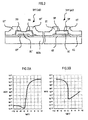
- FIG. 2 is a cross-sectional view illustrating a structure of a complementary thin film transistor in which, along with the p-type thin film transistor TFT (pD), an n-type thin film transistor TFT (nD) is formed on the substrate of the display device according to this embodiment.
- pD p-type thin film transistor
- nD n-type thin film transistor
- the p-type thin film transistor TFT (pD) illustrated in FIG. 2 has the structure similar to that of the p-type thin film transistor TFT (pD) illustrated in FIG. 1A .
- pD p-type thin film transistor TFT
- nD n-type thin film transistor TFT
- a gate electrode GT' is formed on the top surface of the substrate SUB1.
- the gate electrode GT' is formed in the same layer and is made of the same material as the gate electrode GT of the p-type thin film transistor TFT (pD).
- the insulating film GI is formed on the surface of the substrate SUB1 so as to cover the gate electrode GT',
- the insulating film GI is formed so as to be extended from the p-type thin film transistor TFT (pD), and is formed as an extended portion of the insulating film GI of the formation region of the p-type thin film transistor TFT (pD).
- a semiconductor layer SC' made of, for example, a polycrystalline silicon - p-Si - is formed in an island-like pattern so as to overlap the gate electrode GT'.
- the semiconductor layer SC' is formed in the same layer and is made of the same material as the semiconductor layer SC of the p-type thin film transistor TFT (pD).
- a contact layer DO in which p(+)-type impurities are doped is formed on a surface of the semiconductor layer SC', that is, on a surface extending from a top surface to a side-wall surface of the semiconductor layer SC', and is further extended to a surface of the insulating film GI, on which the semiconductor layer SC' is not formed.
- the contact layer DO is not formed in a part exposed from a drain electrode DT' and a source electrode ST', which are described later.
- the semiconductor layer SC' formed under the contact layer DO is exposed from a drain electrode DT' and a source electrode ST'.
- drain electrode DT' and the source electrode ST' are formed above the top surface of the semiconductor layer SC' via the contact layer DO.
- two of the contact layer DO is formed at each of an interface between the drain electrode DT' and the semiconductor layer SC' and an interface between the source electrode ST' and the semiconductor layer SC'.
- the drain electrode DT' and the source electrode ST' are formed in the same layer and are made of the same material as the drain electrode DT and the source electrode ST of the p-type thin film transistor TFT (pD).
- a width of the gate electrode GT is larger than a width of the semiconductor layer SC and is formed beyond a formation region of the semiconductor layer SC. This is for increasing an on-current.
- FIGS. 3A and 3B are graphs illustrating Vg-Id characteristics (characteristics of gate voltage and drain current) of the n-type thin film transistor TFT (nD) and the p-type thin film transistor TFT (pD), respectively.
- a horizontal axis and a vertical axis thereof represent a gate voltage Vg (V) and a drain current Id (A), respectively.
- FIGS. 3A and 3B show a relationship between the gate voltage and the drain current in the case where the drain voltage Vd is 5 V.
- the p-type thin film transistor TFT has sufficiently large current difference between when being turned on and when being turned off and can function as a switching element.
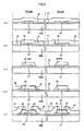
- FIGS. 4(a) to 4(e) is a series of process drawings illustrating an example of a manufacturing method for the n-type thin film transistor TFT (nD) and the p-type thin film transistor TFT (pD) illustrated in FIG. 2 .
- the manufacturing method is described process by process.
- FIGS. 4(a) to 4(e) correspond to the description of FIG. 2 , and manufacturing processes for the n-type thin film transistor TFT (nD) are illustrated on a left side of FIGS. 4(a) to 4(e) , and manufacturing processes for the p-type thin film transistor TFT (pD) are illustrated on a right side thereof.
- the gate electrode GT' and the gate electrode GT are formed on the surface of the substrate SUB1 made of glass, and further, the insulating film GI is formed so as to cover both the gate electrode GT' and the gate electrode GT.
- Both the gate electrode GT' and the gate electrode GT are formed by forming a film (having a film thickness of 50 to 150 nm) made of refractory metal such as molybdenum (Mo) or an alloy thereof by employing sputtering, patterning the formed film by employing a photolithography technology, and then selectively etching the patterned film.
- a film having a film thickness of 50 to 150 nm
- refractory metal such as molybdenum (Mo) or an alloy thereof
- the insulating film GI is formed of SiO, SiN, or a laminated film thereof so as to have a film thickness of 100 to 300 nm.
- a semiconductor layer AS made of an amorphous silicon is formed to have a film thickness of 50 to 300 nm by employing, for example, chemical vapour deposition (CVD).
- CVD chemical vapour deposition
- the semiconductor layer AS is selectively irradiated with pulses or continuous-wave lasers to be crystallized in the formation region of the n-type thin film transistor TFT (nD) and the formation region of the p-type thin film transistor TFT (pD), whereby a semiconductor layer PS made of a polycrystalline silicon is formed. It should be noted that crystallization may be performed over the entire surface of the semiconductor layer AS.
- the semiconductor layer AS is patterned by employing the photolithography technology, and then is selectively etched, with the result that the semiconductor layer PS made of a polycrystalline silicon is left in each of the formation region of the n-type thin film transistor TFT (nD) and the formation region of the p-type thin film transistor TFT (pD).
- the semiconductor layer PS provided in the formation region of the n-type thin film transistor TFT (nD) and the semiconductor layer PS provided in the formation region of the p-type thin film transistor TFT (pD) correspond to the semiconductor layer SC' and the semiconductor layer SC illustrated in FIG. 2 , respectively.
- a semiconductor layer (n(+)-type semiconductor layer) in which phosphorus (P) or the like is doped is formed to have a thickness of 10 to 50 nm by employing CVD.
- the n(+)-type semiconductor layer is patterned by employing the photolithography technology and then is etched to be left on the top surface of the semiconductor layer SC' of the n-type thin film transistor TFT (nD).
- the left n(+)-type semiconductor layer is referred to as the contact layer DO. It should be noted that etching of the n(+)-type semiconductor layer for forming the contact layer DO is also performed in a part which becomes a channel region of the n-type thin film transistor TFT (nD).
- a film made of aluminium (AI) is formed over the entire surface of the substrate SUB1 to have a film thickness of 300 to 500 nm by employing sputtering.
- a film made of refractory metal such as titanium (Ti) or molybdenum (Mo) is formed to have a film thickness of 30 to 100 nm.
- the refractory metal film thus formed is referred to as a so-called barrier metal layer, and is formed to reduce a contact resistance. It should be noted that the barrier metal layer does not have to be formed on the lower surface side of an electrode.
- the AI layer is patterned by employing the photolithography technology and is selectively etched, whereby the drain electrode DT' and the source electrode ST' are formed in the formation region of the n-type thin film transistor TFT (nD), and the drain electrode DT and the source electrode ST are formed in the formation region of the p-type thin film transistor TFT (pD).
- n-type thin film transistor TFT (nD) and the p-type thin film transistor TFT (pD) are covered with the SiN film or the like by employing CVD to form a protective film (not shown) over the entire surface of the substrate SUB1.
- annealing is performed for one to three hours at a temperature of 350 to 450°C in H 2 or N 2 atmosphere.
- aluminium (AI) contained in the drain electrode DT and the source electrode ST of the p-type thin film transistor TFT (pD) is diffused (in the case where the barrier metal layer is provided, is diffused through the barrier metal layer) into the semiconductor layer SC.
- the p(+)-type diffusion layer DF is formed at each of an interface between the drain electrode DT and the semiconductor layer SC and an interface between the source electrode ST and the semiconductor layer SC. It should be noted that the annealing may be performed prior to the formation of the protective film.
- FIG. 5 is a structural view illustrating a display device according to a second embodiment of the present invention, which corresponds to FIG. 2 of the first embodiment of the present invention,
- the same components as those of FIG. 2 are denoted by the same reference symbols and have the same materials and functions as those of FIG. 2 .
- FIG. 5 is different from FIG. 2 in that a diffusion barrier layer BR is formed at an interface between the drain electrode DT' and the contact layer DO in the n-type thin film transistor TFT (nD), and that the diffusion barrier layer BR is formed at an interface between the source electrode ST' and the contact layer DO.
- the diffusion barrier layer BR is a layer for preventing aluminium (AI) forming the drain electrode DT' and the source electrode ST' from diffusing into the contact layer DO during annealing.
- the diffusion barrier layer BR is made of, for example, Mo, Ti, or an alloy thereof, and is formed to have a film thickness to an extent that aluminium (AI) may be prevented from diffusing into the contact layer DO.
- an impurity concentration of the contact layer DO hardly changes and is easily set to a predetermined value.
- FIGS. 6(a) to 6(e) is a series of process drawings illustrating an example of a manufacturing method for the n-type thin film transistor TFT (nD) and the p-type thin film transistor TFT (pD) illustrated in FIG. 5 , in which descriptions thereof are given correspondingly to FIGS. 4(a) to 4(e) of the first embodiment of the present invention,
- the same components as those of FIGS. 4(a) to 4(e) are denoted by the same reference symbols and have the same materials and functions as those of FIGS. 4(a) to 4(e) .
- FIGS. 6(a) to 6(e) are different from FIGS. 4(a) to 4(e) in a process illustrated in FIG. 6(d) .
- a semiconductor layer (n(+)-type semiconductor layer) in which phosphorus (P) or the like is doped and a metal layer made of molybdenum (Mo), titanium (Ti), or an alloy thereof are sequentially formed over the entire surface of the substrate SUB1 by employing CVD.
- the laminated body in which the n(+)-type semiconductor layer and the metal layer are sequentially formed is patterned collectively by employing the photolithography technology and then is etched. Through the etching thus performed, the n(+)-type semiconductor layer and the metal layer are left on the top surface of the semiconductor layer SC' of the n-type thin film transistor TFT (nD).
- the left n(+)-type semiconductor layer is used as the contact layer DO, and the left metal layer is used as the diffusion barrier layer BR.
- the laminated body formed of the n(+)-type semiconductor layer and the metal layer is also etched in a portion serving as the channel region of the n-type thin film transistor TFT (nD).
- the diffusion barrier layer BR may be formed without increasing the number of processes compared with the manufacturing method illustrated in FIGS. 4(a) to 4(e) .
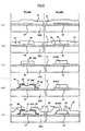
- FIGS. 7(a) to 7(f) is a series of process drawings illustrating a manufacturing method for a display device according to a third embodiment of the present invention.
- a semiconductor layer of an n-type thin film transistor TFT (nP) used for pixel selection is made of an amorphous silicon.
- the process drawings of FIGS. 7(a) to 7(f) illustrate a case where the n-type thin film transistor TFT (nD) and the p-type thin film transistor TFT (pD) for a drive circuit are formed together with the n-type thin film transistor TFT (nP).
- FIGS. 7(a) to 7(f ) the n-type thin film transistor TFT (nD), the p-type thin film transistor TFT (pD), and the n-type thin film transistor TFT (nP) are illustrated in the left, middle, and the right thereof, respectively, Hereinafter, a description is given process by process.
- the gate electrode GT', the gate electrode GT, and a gate electrode GT" are formed on the surface of the substrate SUB1 made of glass, and the insulating film GI is formed so as to cover the gate electrode GT', the gate electrode GT, and the gate electrode GT".
- the gate electrode GT', the gate electrode GT, and the gate electrode GT” are each formed by forming a film (having a film thickness of 50 to 150 nm) made of refractory metal such as molybdenum (Mo) or its alloy by employing sputtering, patterning the formed film by employing the photolithography technology, and selectively etching the patterned film.
- a film having a film thickness of 50 to 150 nm
- refractory metal such as molybdenum (Mo) or its alloy
- the insulating film GI is made of SiO or SiN, or is formed of a laminated film thereof.
- the insulating film GI has a film thickness of 100 to 300 nm.
- the semiconductor layer AS made of an amorphous silicon is formed over the entire top surface of the insulating film GI by employing CVD to have a film thickness of 50 to 300 nm,
- the semiconductor layer AS After performing dehydrogenation treatment on the semiconductor layer AS, the semiconductor layer AS is selectively irradiated with pulses or continuous-wave lasers, and the semiconductor layer AS located in the formation region of the n-type thin film transistor TFT (nD) and the formation region of the p-type thin film transistor TFT (pD) is crystallized, to thereby form the semiconductor layer PS made of a polycrystalline silicon. It should be noted that the semiconductor layer AS may be crystallized over the entire surface thereof.
- the semiconductor layer AS is patterned by employing the photolithography technology, and is further selectively etched, with the result that the semiconductor layer PS made of a polycrystalline silicon is left in each of the formation region of the n-type thin film transistor TFT (nD) and the formation region of the p-type thin film transistor TFT (pD).
- a semiconductor layer AS' made of an amorphous silicon is formed on the surface of the substrate SUB1 by employing, for example, CVD, to have a film thickness of 50 to 250 nm, is patterned by the photolithography technology, and is etched. As a result, the semiconductor layer AS' is left in the respective formation regions of the n-type thin film transistor TFT (nD), the p-type thin film transistor TFT (pD), and the n-type thin film transistor TFT (nP).
- the semiconductor layer AS' is formed so as to be laminated on the semiconductor layer PS in the n-type thin film transistor TFT (nD) and the p-type thin film transistor TFT (pD).
- the semiconductor layer AS' is formed directly on the insulating film GI in the n-type thin film transistor TFT (nP),
- the semiconductor layer is formed as the laminated body in which the semiconductor layer PS made of a polycrystalline silicon and the semiconductor layer AS' made of an amorphous silicon are sequentially laminated.
- the semiconductor layer (n(+)-type semiconductor layer) in which phosphorus (P) or the like is doped by employing CVD is formed over the entire surface of the substrate SUB1 to have a thickness of 10 to 50 nm.
- the n(+)-type semiconductor layer is patterned by employing the photolithography technology and is further etched, and accordingly, is left on a top surface of the semiconductor layer AS' of the n-type thin film transistor TFT (nD) and a top surface of the semiconductor layer AS' of the n-type thin film transistor TFT (nP).
- the n(+)-type semiconductor layer thus left is used as the contact layer DO of the n-type thin film transistor TFT (nD) and the contact layer DO of the n-type thin film transistor TFT (nP).
- the n(+)-type semiconductor layer is also etched in portions which become a channel region of the n-type thin film transistor TFT (nD) and a channel region of the n-type thin film transistor TFT (nP).
- a film made of aluminium (AI) is formed over the entire surface of the substrate SUB1 by employing sputtering to have a film thickness of 300 to 500 nm.
- a film made of refractory metal such as titanium (Ti) or molybdenum (Mo) is formed to have a film thickness of 30 to 100 nm.
- the refractory metal film is referred to as a so-called barrier metal layer, and is formed to reduce a contact resistance.
- the AI layer is patterned by employing the photolithography technology and is selectively etched, with the result that the drain electrode DT' and the source electrode ST' are formed in the formation region of the n-type thin film transistor TFT (nD), the drain electrode DT and the source electrode ST are formed in the formation region of the p-type thin film transistor TFT (pD), and the drain electrode DT" and the source electrode ST" are formed in the formation region of the n-type thin film transistor TFT (nP).
- a protective film made of an SiN film or the like is formed over the entire surface of the substrate SUB1 by employing CVD so as to cover the n-type thin film transistor TFT (nD), the p-type thin film transistor TFT (pD), and the n-type thin film transistor TFT (nP).
- annealing is performed for one to three hours at a temperature of 350 to 450°C in H 2 or N 2 atmosphere.
- aluminium (AI) contained in the drain electrode DT and the source electrode ST of the p-type thin film transistor TFT (pD) is diffused (is diffused through the barrier metal layer) into the semiconductor layer SC (corresponding to the semiconductor layer AS' and the semiconductor layer PS of FIG. 7(f) ).
- a p(+)-type diffusion layer DF is formed at an interface between the drain electrode DT and the semiconductor layer SC and an interface between the source electrode ST and the semiconductor layer SC.
- the annealing may be performed prior to the formation of the protective film.
Landscapes
- Thin Film Transistor (AREA)
- Liquid Crystal (AREA)
- Devices For Indicating Variable Information By Combining Individual Elements (AREA)
Abstract
Description
- The present invention relates to a display device according to the features of the preamble of
claim 1 and a manufacturing method thereof according to the features of the preamble of claim 7. More particularly, the present invention relates to a display device including a thin film transistor formed on a substrate thereof, and to a manufacturing method for the display device. - In an active matrix type display device, a plurality of pixels are arranged in matrix. In addition, gate signal lines are provided so as to be common to the respective pixels arranged in a row direction, and the gate signal lines are selected in an order in which the gate signal lines are provided in a column direction, whereby scanning signals are supplied thereto. Further, at timing at which the gate signal line is selected, a video signal is supplied via a drain signal line common to the respective pixels arranged in the column direction.
- For this reason, each pixel includes a thin film transistor provided for feeding the video signal supplied via the drain signal line to a pixel electrode provided on the pixel through the supply of the scanning signal.
- Further, a drive circuit for supplying the gate signal line with the scanning signal and supplying the drain signal line with the video signal is provided on the same substrate on which the pixels are formed. The drive circuit is formed of a circuit including a plurality of thin film transistors.
- As the thin film transistor included in the drive circuit, there is known a thin film transistor including an n-type thin film transistor and a p-type thin film transistor, in which semiconductor layers of the n-type thin film transistor and the p-type thin film transistor are made of a polycrystalline silicon - low temperature poly-Si- obtained by crystallizing an amorphous silicon. The thin film transistor in which the semiconductor layer is made of the above-mentioned polycrystalline silicon has high field effect mobility, and can drive the drive circuit at high speed.
- For example,
JP 05-63196 A - However, in the case where the n-type thin film transistor and the p-type thin film transistor are each formed of the semiconductor layer made of a polycrystalline silicon, it is necessary to form, between the semiconductor layer made of a polycrystalline silicon and a drain electrode and between the semiconductor layer made of a polycrystalline silicon and a source electrode, an amorphous silicon in which n-type impurities are doped in the case of the n-type thin film transistor, and an amorphous silicon in which p-type impurities are doped in the case of the p-type thin film transistor.
- Therefore, the formation of the amorphous silicon in which n-type impurities are doped and the formation of the amorphous silicon in which p-type impurities are doped need to be performed in different mask processes, which leads to an increase in the number of manufacturing steps.
- Therefore, it is an object of the present invention to provide a display device in which the number of manufacturing steps is reduced,
- Further, it is another object of the present invention to provide a manufacturing method for a display device in which the number of manufacturing steps is reduced.
- These and other objects of the present invention are accomplished generally by a display device comprising the features of
claim 1 and a manufacturing method thereof according to claim 7. - Preferred embodiments of the invention are defined in the dependent claims.
- An outline of the representative aspects of the present invention disclosed in the subject application is described in brief as follows.
- (1) In order to solve the above-mentioned problem, the present invention provides a display device including a p-type thin film transistor formed on a substrate, in which the p-type thin film transistor includes: a gate electrode; a drain electrode; a source electrode; an insulating film; a semiconductor layer formed on a top surface of the gate electrode through the insulating film; and diffusion layers of p-type impurities formed at each of an interface between the drain electrode and the semiconductor layer and an interface between the source electrode and the semiconductor layer, the drain electrode and the source electrode being formed so as to be opposed to each other with a clearance formed there between on a top surface of the semiconductor layer.
- (2) In order to solve the above-mentioned problem, the present invention also provides a display device including a p-type thin film transistor and an n-type thin film transistor which are formed on a substrate, in which: the p-type thin film transistor and the n-type thin film transistor each include: a gate electrode; a drain electrode; a source electrode; an insulating film; and a semiconductor layer formed on a top surface of the gate electrode through the insulating film, the drain electrode and the source electrode being formed so as to be opposed to each other with a clearance formed there between on a top surface of the semiconductor layer; the p-type thin film transistor further includes, at each of an interface between the drain electrode and the semiconductor layer and an interface between the source electrode and the semiconductor layer, diffusion layers of p-type impurities; and the n-type thin film transistor further includes, at each of an interface between the drain electrode and the semiconductor layer and an interface between the source electrode and the semiconductor layer, semiconductor layers in which n-type impurities are doped.
- (3) In the display device according to Item (2), wherein the n-type thin film transistor may further include, at each of the interface between the drain electrode and the semiconductor layer and the interface between the source electrode and the semiconductor layer, diffusion barrier layers for preventing a material of the drain electrode and the source electrode from diffusing into the semiconductor layer, and wherein the semiconductor layers in which n-type impurities are doped and the diffusion barrier layers are respectively accumulated as a sequentially-laminated body.
- (4) In the display device according to Item (1), the drain electrode and the source electrode may be formed of, as a main material, any one material selected from the group consisting of aluminum, gallium, indium, and thallium, and the any one material may be diffused into the semiconductor layer to form the diffusion layer of p-type impurities.
- (5) In the display device according to Item (1), the semiconductor layer may be formed of a polycrystalline semiconductor layer.
- (6) In the display device according to Item (1), the semiconductor layer may be formed of a sequentially-laminated body of a polycrystalline semiconductor layer and an amorphous semiconductor layer.
- (7) In order to solve the above-mentioned problem, the present invention further provides a manufacturing method for a display device including a p-type thin film transistor formed on a substrate, the p-type thin film transistor including: a gate electrode; a drain electrode; a source electrode; an insulating film; and a semiconductor layer formed on a top surface of the gate electrode through the insulating film, the drain electrode and the source electrode being formed so as to be opposed to each other with a clearance formed on a top surface of the semiconductor layer, the manufacturing method including: forming the drain electrode and the source electrode of any one material selected from the group consisting of aluminium, gallium, indium, and thallium as a main material; and forming, at each of an interface between the drain electrode and the semiconductor layer and an interface between the source electrode and the semiconductor layer, diffusion layers of p-type impurities through annealing.
- It should be noted that the present invention is not limited to the structures as described above, and various modifications may be made without departing from the technical idea of the present invention.
- The display device structured as described above may reduce the number of manufacturing steps.
- The manufacturing method for a display device, which is structured as described above, may reduce the number of manufacturing steps,
- Further advantages and possible applications of the present invention become apparent from the following detailed description with reference to the exemplifying embodiments illustrated by way of example in the drawings.
- In the description, the appended claims, the abstract and in the drawings, use is made of the terms and corresponding reference numerals summarized in the list provided at the end of the description. In the drawings:
- FIG. 1A
- is a plan view illustrating an example of a p-type thin film transistor formed on a substrate of a display device according to a first embodiment of the present invention;
- FIG. 1 B
- is a cross-sectional view taken along a line B-B of
FIG. 1A ; - FIG. 2
- is a cross-sectional view illustrating a structure of a complementary thin film transistor including the p-type thin film transistor and an n-type thin film transistor which are formed on the substrate of the display device according to the first embodiment of the present invention;
- FIG. 3A
- is a graph illustrating Vg-Id characteristics of the n-type thin film transistor TFT (nD) of
FIG. 2 ; - FIG. 3B
- is a graph illustrating Vg-Id characteristics of the p-type thin film transistor TFT (pD) of
FIG. 2 ; - FIGS. 4(a) to 4(e)
- is a series of process drawings illustrating an example of a manufacturing method for the n-type thin film transistor and the p-type thin film transistor which are illustrated in
FIG. 2 ; - FIG. 5
- is a structural view illustrating a p-type thin film transistor and an n-type thin film transistor which are formed on a substrate of a display device according to a second embodiment of the present invention;
- FIGS. 6(a) to 6(e)
- is a series of process drawings illustrating an example of a manufacturing method for the n-type thin film transistor and the p-type thin film transistor which are illustrated in
FIG. 5 ; - FIGS. 7(a) to 7(f)
- is a series of process drawings illustrating a manufacturing method for a display device according to a third embodiment of the present invention; and
- FIG. 8A
- is a schematic structural view illustrating a display device according to the first embodiment of the present invention.
- FIG. 8B
- is a magnified view illustrating an area circled by dotted frame B in the
FIG. 8A . - Hereinafter, with reference to the drawings, a display device according to the present invention is described by way of embodiments.
-
FIG. 8A is a schematic structural view illustrating a display device according to an embodiment of the present invention. InFIG. 8A , a liquid crystal display device is taken as an example. - A substrate SUB1 and a substrate SUB2 are provided to face each other through liquid crystal sandwiched there between, and a liquid crystal display area AR is formed on a surface of the substrate SUB2 on a side opposite to a side of the substrate SUB2 on which the liquid crystal is held.
- In the liquid crystal display area AR, a plurality of pixels arranged in matrix are formed on the side of the substrate SUB1 and the substrate SUB2 on which the liquid crystal is sandwiched there between.
-
FIG. 8B is a magnified view illustrating an area circled by dotted frame B in theFIG. 8A . As illustrated inFIG.8B , those pixels arranged in matrix are each formed within an area surrounded by each of drain signal lines DL which are extended in a y direction and provided side by side in a x direction ofFIG. 8A and each of gate signal lines GL which are extended in the x direction and provided side by side in the y direction ofFIG. 8A . - Each pixel includes a thin film transistor TFT - referred to as TFT (nP) to distinguish from other thin film transistor TFT described later - which is turned on by a scanning signal (voltage) sent from the gate signal line GL, a pixel electrode PX to which a video signal (voltage) sent from the drain signal line DL is supplied via the turned-on thin film transistor TFT (nP), and a counter electrode CT which generates an electric field between the pixel electrode PX and itself.
- It should be noted that the counter electrode CT is connected to a counter voltage signal line CL which is arranged in parallel with the gate signal line GL, and a signal (voltage) which becomes a reference with respect to the video signal is supplied thereto via the counter voltage signal line CL.
- In a part in which the substrate SUB1 is exposed from the substrate SUB2 on an outside (left side in
FIG. 8A ) of the liquid crystal display area AR, there is formed a drive circuit DRC for sequentially supplying the gate signal lines GL with the scanning signals and supplying the drain signal lines DL with video signals at timing at which the scanning signal is supplied. The drive circuit DRC includes the n-type thin film transistor TFT (nD) and a p-type thin film transistor TFT (pD). - Further, in a part in which the substrate SUB1 is exposed from the substrate SUB2 on another outside - downside in
FIG. 8A - of the liquid crystal display area AR, there is formed an RGB switching circuit CSC for switching and connecting the drain signal lines DL, which manage each of the three primary colours in a unit pixel of colour display, for each colour. The RGB switching circuit CSC includes the thin film transistor TFT (nD) and the thin film transistor TFT (pD) which correspond to those of the drive circuit DRC. The RGB switching circuit CSC has the substantially same structure as that of the drive circuit DRC, in which the thin film transistor TFT (nD) and the thin film transistor TFT (pD) thereof are formed in parallel with the formation of the thin film transistor TFT (nD) and the thin film transistor TFT (pD) of the drive circuit DRC. For this reason, the n-type thin film transistor and the p-type thin film transistor of the RGB switching circuit CSC are also denoted by reference symbols TFT (nD) and TFT (pD), respectively.
p-type thin film transistor -
FIG. 1A is a plan view illustrating an example of the p-type thin film transistor TFT (pD).FIG. 1 B =is a cross-sectional view taken along a line B-B ofFIG. 1A . - As illustrated in
FIG. 1 B , a gate electrode GT is formed on a surface of the substrate SUB1. The gate electrode GT is formed on the surface of the substrate SUB1 so as to be extended in the y direction ofFIG. 1A , as illustrated inFIG. 1A . - In addition, an insulating film GI is formed on the surface of the substrate SUB1 so as to cover the gate electrode GT. The insulating film GI functions as a gate insulating film of the p-type thin film transistor TFT (pD) in a formation region of the p-type thin film transistor TFT (pD).
- On a top surface of the insulating film GI, a semiconductor layer SC made of a polycrystalline silicon - p-Si - is formed in an island-like pattern so as to overlap the gate electrode GT. The semiconductor layer SC forms an i-type semiconductor layer in which impurities are not doped.
- Further, a pair of electrodes DT and ST which are formed on a top surface of the semiconductor layer SC to face each other with a clearance being formed above the gate electrode GT. The electrodes DT and ST are formed to face each other while being spaced apart from each other. The electrodes DT and ST are formed on the insulating film GI and the electrodes DT and ST are extended in the x direction of
FIG. 1A . - An area of the semiconductor layer SC, which is the clearance between the electrodes DT and ST, forms a channel region, and a distance between the electrodes DT and ST corresponds to a channel length of the p-type thin film transistor TFT (pD).
- Those electrodes DT and ST are made of, for example, aluminium (AI). The electrodes DT and ST may be made of only aluminium, and may be made of aluminium as a main material and other metal. When annealing is performed at, for example, about 400°C after the formation of the electrodes DT and ST, aluminium is diffused into the semiconductor layer SC, and a p(+)-type diffusion layer DF is formed at an interface between the electrode DT and the semiconductor layer SC and an interface between the electrode ST and the semiconductor layer SC.
- The p-type thin film transistor TFT (pD) as described above forms a bottom-gate-type metal insulator semiconductor (MIS) transistor. Through application of a bias voltage, one of the electrodes DT and ST functions as a drain electrode, and the other thereof functions as a source electrode. For the sake of convenience, herein, an electrode located on the left side of
FIG. 1A and 1B and an electrode located on the right side thereof are referred to as the drain electrode DT and the source electrode ST, respectively. - In the p-type thin film transistor TFT (pD) structured as described above, there is no particular need to form a contact layer between the drain electrode DT and the semiconductor layer SC, and between the source electrode ST and the semiconductor layer SC. Accordingly, the p-type thin film transistor TFT (pD) may be formed with a simple process.
- It should be noted that, in this embodiment, aluminium is used as a main material for the drain electrode DT and the source electrode ST of the p-type thin film transistor TFT (pD), but other material such as gallium (Ga), indium (In), or thallium (TI) may be used as the main material therefore. Even when the material as described above is used, the p(+)-type diffusion layer DF may be formed at each of the interface between the drain electrode DT and the semiconductor layer SC, and the interface between the source electrode ST and the semiconductor layer SC.
p-type thin film transistor and n-type thin film transistor -
FIG. 2 is a cross-sectional view illustrating a structure of a complementary thin film transistor in which, along with the p-type thin film transistor TFT (pD), an n-type thin film transistor TFT (nD) is formed on the substrate of the display device according to this embodiment. - The p-type thin film transistor TFT (pD) illustrated in
FIG. 2 has the structure similar to that of the p-type thin film transistor TFT (pD) illustrated inFIG. 1A . Thus, in the description below, a structure of the n-type thin film transistor TFT (nD) formed on a left side ofFIG. 2 is described. - As illustrated on the left side in
FIG. 2 , a gate electrode GT' is formed on the top surface of the substrate SUB1. The gate electrode GT' is formed in the same layer and is made of the same material as the gate electrode GT of the p-type thin film transistor TFT (pD). - The insulating film GI is formed on the surface of the substrate SUB1 so as to cover the gate electrode GT', The insulating film GI is formed so as to be extended from the p-type thin film transistor TFT (pD), and is formed as an extended portion of the insulating film GI of the formation region of the p-type thin film transistor TFT (pD).
- On the top surface of the insulating film GI, a semiconductor layer SC' made of, for example, a polycrystalline silicon - p-Si - is formed in an island-like pattern so as to overlap the gate electrode GT'.
- The semiconductor layer SC' is formed in the same layer and is made of the same material as the semiconductor layer SC of the p-type thin film transistor TFT (pD).
- Further, a contact layer DO in which p(+)-type impurities are doped is formed on a surface of the semiconductor layer SC', that is, on a surface extending from a top surface to a side-wall surface of the semiconductor layer SC', and is further extended to a surface of the insulating film GI, on which the semiconductor layer SC' is not formed.
- It should be noted that the contact layer DO is not formed in a part exposed from a drain electrode DT' and a source electrode ST', which are described later. The semiconductor layer SC' formed under the contact layer DO is exposed from a drain electrode DT' and a source electrode ST'.
- Further, the drain electrode DT' and the source electrode ST' are formed above the top surface of the semiconductor layer SC' via the contact layer DO. As a result, two of the contact layer DO is formed at each of an interface between the drain electrode DT' and the semiconductor layer SC' and an interface between the source electrode ST' and the semiconductor layer SC'.
- The drain electrode DT' and the source electrode ST' are formed in the same layer and are made of the same material as the drain electrode DT and the source electrode ST of the p-type thin film transistor TFT (pD).
- As apparent from comparing with the n-type thin film transistor TFT (nD), in the p-type thin film transistor TFT (pD), a width of the gate electrode GT is larger than a width of the semiconductor layer SC and is formed beyond a formation region of the semiconductor layer SC. This is for increasing an on-current.
-
FIGS. 3A and 3B are graphs illustrating Vg-Id characteristics (characteristics of gate voltage and drain current) of the n-type thin film transistor TFT (nD) and the p-type thin film transistor TFT (pD), respectively, InFIGS. 3A and 3B , a horizontal axis and a vertical axis thereof represent a gate voltage Vg (V) and a drain current Id (A), respectively.FIGS. 3A and 3B show a relationship between the gate voltage and the drain current in the case where the drain voltage Vd is 5 V. - Accordingly, it may be found that the p-type thin film transistor TFT (pD) has sufficiently large current difference between when being turned on and when being turned off and can function as a switching element.
- Manufacturing Method
-
FIGS. 4(a) to 4(e) is a series of process drawings illustrating an example of a manufacturing method for the n-type thin film transistor TFT (nD) and the p-type thin film transistor TFT (pD) illustrated inFIG. 2 . Hereinafter, the manufacturing method is described process by process. -
FIGS. 4(a) to 4(e) correspond to the description ofFIG. 2 , and manufacturing processes for the n-type thin film transistor TFT (nD) are illustrated on a left side ofFIGS. 4(a) to 4(e) , and manufacturing processes for the p-type thin film transistor TFT (pD) are illustrated on a right side thereof. - Hereinafter, the manufacturing method is described process by process.
- The gate electrode GT' and the gate electrode GT are formed on the surface of the substrate SUB1 made of glass, and further, the insulating film GI is formed so as to cover both the gate electrode GT' and the gate electrode GT.
- Both the gate electrode GT' and the gate electrode GT are formed by forming a film (having a film thickness of 50 to 150 nm) made of refractory metal such as molybdenum (Mo) or an alloy thereof by employing sputtering, patterning the formed film by employing a photolithography technology, and then selectively etching the patterned film.
- The insulating film GI is formed of SiO, SiN, or a laminated film thereof so as to have a film thickness of 100 to 300 nm.
- Then, over the entire top surface of the insulating film GI, a semiconductor layer AS made of an amorphous silicon is formed to have a film thickness of 50 to 300 nm by employing, for example, chemical vapour deposition (CVD).
- After performing dehydrogenation treatment on the semiconductor layer AS, the semiconductor layer AS is selectively irradiated with pulses or continuous-wave lasers to be crystallized in the formation region of the n-type thin film transistor TFT (nD) and the formation region of the p-type thin film transistor TFT (pD), whereby a semiconductor layer PS made of a polycrystalline silicon is formed. It should be noted that crystallization may be performed over the entire surface of the semiconductor layer AS.
- The semiconductor layer AS is patterned by employing the photolithography technology, and then is selectively etched, with the result that the semiconductor layer PS made of a polycrystalline silicon is left in each of the formation region of the n-type thin film transistor TFT (nD) and the formation region of the p-type thin film transistor TFT (pD).
- The semiconductor layer PS provided in the formation region of the n-type thin film transistor TFT (nD) and the semiconductor layer PS provided in the formation region of the p-type thin film transistor TFT (pD) correspond to the semiconductor layer SC' and the semiconductor layer SC illustrated in
FIG. 2 , respectively. - Over the entire surface of the substrate SUB1, a semiconductor layer (n(+)-type semiconductor layer) in which phosphorus (P) or the like is doped is formed to have a thickness of 10 to 50 nm by employing CVD.
- Then, the n(+)-type semiconductor layer is patterned by employing the photolithography technology and then is etched to be left on the top surface of the semiconductor layer SC' of the n-type thin film transistor TFT (nD). Here, the left n(+)-type semiconductor layer is referred to as the contact layer DO. It should be noted that etching of the n(+)-type semiconductor layer for forming the contact layer DO is also performed in a part which becomes a channel region of the n-type thin film transistor TFT (nD).
- A film made of aluminium (AI) is formed over the entire surface of the substrate SUB1 to have a film thickness of 300 to 500 nm by employing sputtering.
- On this occasion, on upper and lower surfaces of the AI layer, a film made of refractory metal such as titanium (Ti) or molybdenum (Mo) is formed to have a film thickness of 30 to 100 nm. The refractory metal film thus formed is referred to as a so-called barrier metal layer, and is formed to reduce a contact resistance. It should be noted that the barrier metal layer does not have to be formed on the lower surface side of an electrode.
- After that, the AI layer is patterned by employing the photolithography technology and is selectively etched, whereby the drain electrode DT' and the source electrode ST' are formed in the formation region of the n-type thin film transistor TFT (nD), and the drain electrode DT and the source electrode ST are formed in the formation region of the p-type thin film transistor TFT (pD).
- Further, the n-type thin film transistor TFT (nD) and the p-type thin film transistor TFT (pD) are covered with the SiN film or the like by employing CVD to form a protective film (not shown) over the entire surface of the substrate SUB1.
- Then, annealing is performed for one to three hours at a temperature of 350 to 450°C in H2 or N2 atmosphere. Through the annealing thus performed, aluminium (AI) contained in the drain electrode DT and the source electrode ST of the p-type thin film transistor TFT (pD) is diffused (in the case where the barrier metal layer is provided, is diffused through the barrier metal layer) into the semiconductor layer SC. As a result, the p(+)-type diffusion layer DF is formed at each of an interface between the drain electrode DT and the semiconductor layer SC and an interface between the source electrode ST and the semiconductor layer SC. It should be noted that the annealing may be performed prior to the formation of the protective film.
-
FIG. 5 is a structural view illustrating a display device according to a second embodiment of the present invention, which corresponds toFIG. 2 of the first embodiment of the present invention, InFIG. 5 , the same components as those ofFIG. 2 are denoted by the same reference symbols and have the same materials and functions as those ofFIG. 2 . -
FIG. 5 is different fromFIG. 2 in that a diffusion barrier layer BR is formed at an interface between the drain electrode DT' and the contact layer DO in the n-type thin film transistor TFT (nD), and that the diffusion barrier layer BR is formed at an interface between the source electrode ST' and the contact layer DO. - The diffusion barrier layer BR is a layer for preventing aluminium (AI) forming the drain electrode DT' and the source electrode ST' from diffusing into the contact layer DO during annealing.
- The diffusion barrier layer BR is made of, for example, Mo, Ti, or an alloy thereof, and is formed to have a film thickness to an extent that aluminium (AI) may be prevented from diffusing into the contact layer DO.
- In such a case, an impurity concentration of the contact layer DO hardly changes and is easily set to a predetermined value.
-
FIGS. 6(a) to 6(e) is a series of process drawings illustrating an example of a manufacturing method for the n-type thin film transistor TFT (nD) and the p-type thin film transistor TFT (pD) illustrated inFIG. 5 , in which descriptions thereof are given correspondingly toFIGS. 4(a) to 4(e) of the first embodiment of the present invention, InFIGS. 6(a) to 6(e) , the same components as those ofFIGS. 4(a) to 4(e) are denoted by the same reference symbols and have the same materials and functions as those ofFIGS. 4(a) to 4(e) . -
FIGS. 6(a) to 6(e) are different fromFIGS. 4(a) to 4(e) in a process illustrated inFIG. 6(d) . - That is, in
FIG. 6(d) , a semiconductor layer (n(+)-type semiconductor layer) in which phosphorus (P) or the like is doped and a metal layer made of molybdenum (Mo), titanium (Ti), or an alloy thereof are sequentially formed over the entire surface of the substrate SUB1 by employing CVD. - Then, the laminated body in which the n(+)-type semiconductor layer and the metal layer are sequentially formed is patterned collectively by employing the photolithography technology and then is etched. Through the etching thus performed, the n(+)-type semiconductor layer and the metal layer are left on the top surface of the semiconductor layer SC' of the n-type thin film transistor TFT (nD). The left n(+)-type semiconductor layer is used as the contact layer DO, and the left metal layer is used as the diffusion barrier layer BR. The laminated body formed of the n(+)-type semiconductor layer and the metal layer is also etched in a portion serving as the channel region of the n-type thin film transistor TFT (nD).
- According to the manufacturing method as described above, the diffusion barrier layer BR may be formed without increasing the number of processes compared with the manufacturing method illustrated in
FIGS. 4(a) to 4(e) . -
FIGS. 7(a) to 7(f) is a series of process drawings illustrating a manufacturing method for a display device according to a third embodiment of the present invention. - In a display device illustrated in
FIGS, 7(a) to 7(f) , a semiconductor layer of an n-type thin film transistor TFT (nP) used for pixel selection is made of an amorphous silicon. The process drawings ofFIGS. 7(a) to 7(f) illustrate a case where the n-type thin film transistor TFT (nD) and the p-type thin film transistor TFT (pD) for a drive circuit are formed together with the n-type thin film transistor TFT (nP). - In
FIGS. 7(a) to 7(f ), the n-type thin film transistor TFT (nD), the p-type thin film transistor TFT (pD), and the n-type thin film transistor TFT (nP) are illustrated in the left, middle, and the right thereof, respectively, Hereinafter, a description is given process by process. - The gate electrode GT', the gate electrode GT, and a gate electrode GT" are formed on the surface of the substrate SUB1 made of glass, and the insulating film GI is formed so as to cover the gate electrode GT', the gate electrode GT, and the gate electrode GT".
- The gate electrode GT', the gate electrode GT, and the gate electrode GT" are each formed by forming a film (having a film thickness of 50 to 150 nm) made of refractory metal such as molybdenum (Mo) or its alloy by employing sputtering, patterning the formed film by employing the photolithography technology, and selectively etching the patterned film.
- For example, the insulating film GI is made of SiO or SiN, or is formed of a laminated film thereof. And the insulating film GI has a film thickness of 100 to 300 nm.
- Then, the semiconductor layer AS made of an amorphous silicon is formed over the entire top surface of the insulating film GI by employing CVD to have a film thickness of 50 to 300 nm,
- After performing dehydrogenation treatment on the semiconductor layer AS, the semiconductor layer AS is selectively irradiated with pulses or continuous-wave lasers, and the semiconductor layer AS located in the formation region of the n-type thin film transistor TFT (nD) and the formation region of the p-type thin film transistor TFT (pD) is crystallized, to thereby form the semiconductor layer PS made of a polycrystalline silicon. It should be noted that the semiconductor layer AS may be crystallized over the entire surface thereof.
- The semiconductor layer AS is patterned by employing the photolithography technology, and is further selectively etched, with the result that the semiconductor layer PS made of a polycrystalline silicon is left in each of the formation region of the n-type thin film transistor TFT (nD) and the formation region of the p-type thin film transistor TFT (pD).
- A semiconductor layer AS' made of an amorphous silicon is formed on the surface of the substrate SUB1 by employing, for example, CVD, to have a film thickness of 50 to 250 nm, is patterned by the photolithography technology, and is etched. As a result, the semiconductor layer AS' is left in the respective formation regions of the n-type thin film transistor TFT (nD), the p-type thin film transistor TFT (pD), and the n-type thin film transistor TFT (nP).
- Accordingly, the semiconductor layer AS' is formed so as to be laminated on the semiconductor layer PS in the n-type thin film transistor TFT (nD) and the p-type thin film transistor TFT (pD). On the other hand, the semiconductor layer AS' is formed directly on the insulating film GI in the n-type thin film transistor TFT (nP),
- In other words, in the n-type thin film transistor TFT (nD) and the p-type thin film transistor TFT (pD), the semiconductor layer is formed as the laminated body in which the semiconductor layer PS made of a polycrystalline silicon and the semiconductor layer AS' made of an amorphous silicon are sequentially laminated.
- Process 5. (
FIG. 7(e) ) - The semiconductor layer (n(+)-type semiconductor layer) in which phosphorus (P) or the like is doped by employing CVD is formed over the entire surface of the substrate SUB1 to have a thickness of 10 to 50 nm.
- Then, the n(+)-type semiconductor layer is patterned by employing the photolithography technology and is further etched, and accordingly, is left on a top surface of the semiconductor layer AS' of the n-type thin film transistor TFT (nD) and a top surface of the semiconductor layer AS' of the n-type thin film transistor TFT (nP). The n(+)-type semiconductor layer thus left is used as the contact layer DO of the n-type thin film transistor TFT (nD) and the contact layer DO of the n-type thin film transistor TFT (nP). The n(+)-type semiconductor layer is also etched in portions which become a channel region of the n-type thin film transistor TFT (nD) and a channel region of the n-type thin film transistor TFT (nP).
- A film made of aluminium (AI) is formed over the entire surface of the substrate SUB1 by employing sputtering to have a film thickness of 300 to 500 nm.
- On this occasion, on upper and lower surfaces of the AI layer, a film made of refractory metal such as titanium (Ti) or molybdenum (Mo) is formed to have a film thickness of 30 to 100 nm. The refractory metal film is referred to as a so-called barrier metal layer, and is formed to reduce a contact resistance.
- After that, the AI layer is patterned by employing the photolithography technology and is selectively etched, with the result that the drain electrode DT' and the source electrode ST' are formed in the formation region of the n-type thin film transistor TFT (nD), the drain electrode DT and the source electrode ST are formed in the formation region of the p-type thin film transistor TFT (pD), and the drain electrode DT" and the source electrode ST" are formed in the formation region of the n-type thin film transistor TFT (nP).
- Further, a protective film (not shown) made of an SiN film or the like is formed over the entire surface of the substrate SUB1 by employing CVD so as to cover the n-type thin film transistor TFT (nD), the p-type thin film transistor TFT (pD), and the n-type thin film transistor TFT (nP).
- Then, annealing is performed for one to three hours at a temperature of 350 to 450°C in H2 or N2 atmosphere. Through the annealing thus performed, aluminium (AI) contained in the drain electrode DT and the source electrode ST of the p-type thin film transistor TFT (pD) is diffused (is diffused through the barrier metal layer) into the semiconductor layer SC (corresponding to the semiconductor layer AS' and the semiconductor layer PS of
FIG. 7(f) ). As a result, a p(+)-type diffusion layer DF is formed at an interface between the drain electrode DT and the semiconductor layer SC and an interface between the source electrode ST and the semiconductor layer SC. It should be noted that the annealing may be performed prior to the formation of the protective film. - The respective embodiments described above may be used independently or in combination. This is because the effects of the respective embodiments may be achieved independently or synergistically.
- While there have been described what are at present considered to be certain embodiments of the invention, it will be understood that various modifications may be made thereto, and it is intended that the appended claims cover all such modifications as fall within the true spirit and scope of the invention.
-
- SUB1
- substrate
- SUB2
- substrate
- AR
- liquid crystal display area
- DL
- drain signal lines
- GL
- gate signal lines
- TFT(pD)
- p-type thin film transistor
- TFT(nD)
- n-type thin film transistor
- PX
- pixel electrode
- CT
- counter electrode
- CL
- counter voltage signal line
- DRC
- drive circuit
- CSC
- RGB switching circuit
- GT, GT', GT"
- gate electrode
- GI
- insulating film
- SC, SC'
- semiconductor layer
- DT, DT', DT"
- electrode / drain electrode
- ST, ST', ST"
- electrode / source electrode
- DO
- contact layer
- AS, AS'
- semiconductor layer
- PS
- semiconductor layer
- DF
- diffusion layer
- BR
- diffusion barrier layer
- Vg
- gate voltage
- Id
- drain current
Claims (7)
- A display device, comprising a p-type thin film transistor formed on a substrate, characterized in that the p-type thin film transistor includes:a gate electrode;a drain electrode;a source electrode;an insulating film;a semiconductor layer formed on a top surface of the gate electrode through the insulating film; anddiffusion layers of p-type impurities formed at each of an interface between the drain electrode and the semiconductor layer and an interface between the source electrode and the semiconductor layer,the drain electrode and the source electrode being formed so as to be opposed to each other with a clearance formed there between on a top surface of the semiconductor layer.
- A display device, comprising a p-type thin film transistor and an n-type thin film transistor which are formed on a substrate, characterized in that:the p-type thin film transistor and the n-type thin film transistor each include:a gate electrode;a drain electrode;a source electrode;an insulating film; anda semiconductor layer formed on a top surface of the gate electrode through the insulating film,the drain electrode and the source electrode being formed so as to be opposed to each other with a clearance formed there between on a top surface of the semiconductor layer;the p-type thin film transistor further includes, at each of an interface between the drain electrode and the semiconductor layer and an interface between the source electrode and the semiconductor layer, diffusion layers of p-type impurities; andthe n-type thin film transistor further includes, at each of an interface between the drain electrode and the semiconductor layer and an interface between the source electrode and the semiconductor layer, semiconductor layers in which n-type impurities are doped.
- The display device according to claim 2, characterized in that the n-type thin film transistor further includes, at each of the interface between the drain electrode and the semiconductor layer and the interface between the source electrode and the semiconductor layer, diffusion barrier layers for preventing a material of the drain electrode and the source electrode from diffusing into the semiconductor layer, and wherein the semiconductor layers in which n-type impurities are doped and the diffusion barrier layers are respectively accumulated as a sequentially-laminated body,
- The display device according to claim 1, characterized in that the drain electrode and the source electrode are formed of, as a main material, any one material selected from the group consisting of aluminium, gallium, indium, and thallium, and the any one material is diffused into the semiconductor layer to form the diffusion layer of p-type impurities,
- The display device according to claim 1 or 4, characterized in that the semiconductor layer is formed of a polycrystalline semiconductor layer.
- The display device according to claim 1, 4 or 5, characterized in that the semiconductor layer is formed of a sequentially-laminated body of a polycrystalline semiconductor layer and an amorphous semiconductor layer.
- A manufacturing method for a display device comprising a p-type thin film transistor formed on a substrate, the p-type thin film transistor including:a gate electrode;a drain electrode;a source electrode;an insulating film; anda semiconductor layer formed on a top surface of the gate electrode through the insulating film, the drain electrode and the source electrode being formed so as to be opposed to each other with a clearance formed on a top surface of the semiconductor layer, the manufacturing method comprising:forming the drain electrode and the source electrode of any one material selected from the group consisting of aluminium, gallium, indium, and thallium as a main material; andforming, at each of an interface between the drain electrode and the semiconductor layer andan interface between the source electrode and the semiconductor layer, diffusion layers of p-type impurities through annealing.
Applications Claiming Priority (1)
| Application Number | Priority Date | Filing Date | Title |
|---|---|---|---|
| JP2008049885A JP5363009B2 (en) | 2008-02-29 | 2008-02-29 | Display device and manufacturing method thereof |
Publications (3)
| Publication Number | Publication Date |
|---|---|
| EP2096673A2 true EP2096673A2 (en) | 2009-09-02 |
| EP2096673A3 EP2096673A3 (en) | 2011-04-20 |
| EP2096673B1 EP2096673B1 (en) | 2021-06-02 |
Family
ID=40719637
Family Applications (1)
| Application Number | Title | Priority Date | Filing Date |
|---|---|---|---|
| EP09153984.1A Active EP2096673B1 (en) | 2008-02-29 | 2009-02-27 | Method of manufacturing display device |
Country Status (6)
| Country | Link |
|---|---|
| US (1) | US8058654B2 (en) |
| EP (1) | EP2096673B1 (en) |
| JP (1) | JP5363009B2 (en) |
| KR (1) | KR101043115B1 (en) |
| CN (1) | CN101521210B (en) |
| TW (1) | TWI401805B (en) |
Cited By (1)
| Publication number | Priority date | Publication date | Assignee | Title |
|---|---|---|---|---|
| US11282865B2 (en) | 2014-06-20 | 2022-03-22 | Semiconductor Energy Laboratory Co., Ltd. | Semiconductor device including indium at insulating film interface |
Families Citing this family (6)
| Publication number | Priority date | Publication date | Assignee | Title |
|---|---|---|---|---|
| JP5111167B2 (en) * | 2008-03-06 | 2012-12-26 | 株式会社ジャパンディスプレイイースト | Liquid crystal display |
| FR2944140B1 (en) * | 2009-04-02 | 2011-09-16 | Commissariat Energie Atomique | DEVICE FOR DETECTING ELECTRONIC IMAGE |
| KR20110081694A (en) * | 2010-01-08 | 2011-07-14 | 삼성모바일디스플레이주식회사 | Manufacturing method of thin film transistor and manufacturing method of display device |
| JP5708910B2 (en) | 2010-03-30 | 2015-04-30 | ソニー株式会社 | THIN FILM TRANSISTOR, MANUFACTURING METHOD THEREOF, AND DISPLAY DEVICE |
| JP6544166B2 (en) * | 2015-09-14 | 2019-07-17 | 信越化学工業株式会社 | Method of manufacturing SiC composite substrate |
| CN105470310A (en) * | 2016-01-21 | 2016-04-06 | 京东方科技集团股份有限公司 | Thin-film transistor and fabrication method thereof, array substrate and display device |
Citations (1)
| Publication number | Priority date | Publication date | Assignee | Title |
|---|---|---|---|---|
| JPH0563196A (en) | 1991-09-04 | 1993-03-12 | Hitachi Ltd | Thin film semiconductor device, manufacture thereof and liquid crystal display device |
Family Cites Families (21)
| Publication number | Priority date | Publication date | Assignee | Title |
|---|---|---|---|---|
| GB2044994B (en) | 1979-03-22 | 1983-06-15 | Philips Electronic Associated | Thin film transistors |
| JPH0693509B2 (en) | 1983-08-26 | 1994-11-16 | シャープ株式会社 | Thin film transistor |
| ATE77177T1 (en) | 1985-10-04 | 1992-06-15 | Hosiden Corp | THIN FILM TRANSISTOR AND METHOD FOR ITS MANUFACTURE. |
| JPH06188265A (en) | 1992-12-22 | 1994-07-08 | Matsushita Electric Ind Co Ltd | Semiconductor device and manufacture thereof |
| JPH08204032A (en) * | 1995-01-20 | 1996-08-09 | Mitsubishi Electric Corp | Semiconductor device and manufacturing method thereof |
| JP3516424B2 (en) * | 1996-03-10 | 2004-04-05 | 株式会社半導体エネルギー研究所 | Thin film semiconductor device |
| JP2757850B2 (en) | 1996-04-18 | 1998-05-25 | 日本電気株式会社 | Thin film transistor and method of manufacturing the same |
| JP4019461B2 (en) * | 1996-09-06 | 2007-12-12 | セイコーエプソン株式会社 | Color display device, manufacturing method thereof, and color liquid crystal device |
| US6620719B1 (en) * | 2000-03-31 | 2003-09-16 | International Business Machines Corporation | Method of forming ohmic contacts using a self doping layer for thin-film transistors |
| JP2002202527A (en) * | 2000-12-28 | 2002-07-19 | Nec Corp | Active matrix type liquid crystal display |
| JP2004079735A (en) | 2002-08-15 | 2004-03-11 | Nec Corp | Method for manufacturing thin film transistor |
| TW554539B (en) * | 2002-09-09 | 2003-09-21 | Chunghwa Picture Tubes Ltd | Thin film transistor source/drain structure and manufacturing method thereof |
| KR100904266B1 (en) | 2002-12-31 | 2009-06-25 | 엘지디스플레이 주식회사 | Method of manufacturing thin film transistor array substrate |
| JP4316896B2 (en) * | 2003-01-09 | 2009-08-19 | 株式会社 日立ディスプレイズ | Display device and manufacturing method thereof |
| KR100584715B1 (en) * | 2004-04-06 | 2006-05-29 | 엘지.필립스 엘시디 주식회사 | Manufacturing method of array substrate for liquid crystal display device with integrated drive circuit |
| JP5036173B2 (en) * | 2004-11-26 | 2012-09-26 | 株式会社半導体エネルギー研究所 | Method for manufacturing semiconductor device |
| US20060138403A1 (en) * | 2004-12-29 | 2006-06-29 | Gang Yu | Organic electronic devices including pixels |
| US7521710B2 (en) * | 2006-02-16 | 2009-04-21 | Idemitsu Kosan Co., Ltd. | Organic thin film transistor |
| US7646015B2 (en) * | 2006-10-31 | 2010-01-12 | Semiconductor Energy Laboratory Co., Ltd. | Manufacturing method of semiconductor device and semiconductor device |
| JP5303119B2 (en) * | 2007-06-05 | 2013-10-02 | 株式会社ジャパンディスプレイ | Semiconductor device |
| JP2008311545A (en) * | 2007-06-18 | 2008-12-25 | Hitachi Displays Ltd | Display device |
-
2008
- 2008-02-29 JP JP2008049885A patent/JP5363009B2/en active Active
-
2009
- 2009-02-12 CN CN2009100057992A patent/CN101521210B/en active Active
- 2009-02-19 TW TW098105315A patent/TWI401805B/en active
- 2009-02-26 US US12/379,662 patent/US8058654B2/en active Active
- 2009-02-26 KR KR1020090016353A patent/KR101043115B1/en active Active
- 2009-02-27 EP EP09153984.1A patent/EP2096673B1/en active Active
Patent Citations (1)
| Publication number | Priority date | Publication date | Assignee | Title |
|---|---|---|---|---|
| JPH0563196A (en) | 1991-09-04 | 1993-03-12 | Hitachi Ltd | Thin film semiconductor device, manufacture thereof and liquid crystal display device |
Cited By (1)
| Publication number | Priority date | Publication date | Assignee | Title |
|---|---|---|---|---|
| US11282865B2 (en) | 2014-06-20 | 2022-03-22 | Semiconductor Energy Laboratory Co., Ltd. | Semiconductor device including indium at insulating film interface |
Also Published As
| Publication number | Publication date |
|---|---|
| CN101521210A (en) | 2009-09-02 |
| TWI401805B (en) | 2013-07-11 |
| US8058654B2 (en) | 2011-11-15 |
| KR20090093849A (en) | 2009-09-02 |
| JP2009206437A (en) | 2009-09-10 |
| CN101521210B (en) | 2012-05-23 |
| JP5363009B2 (en) | 2013-12-11 |
| TW201001711A (en) | 2010-01-01 |
| KR101043115B1 (en) | 2011-06-20 |
| EP2096673B1 (en) | 2021-06-02 |
| US20090218575A1 (en) | 2009-09-03 |
| EP2096673A3 (en) | 2011-04-20 |
Similar Documents
| Publication | Publication Date | Title |
|---|---|---|
| CN101414638B (en) | Display device and method of manufacturing display device | |
| US8058654B2 (en) | Display device and manufacturing method thereof | |
| WO2018180617A1 (en) | Active matrix substrate, liquid crystal display device, and organic el display device | |
| US20190243194A1 (en) | Active matrix substrate and method for manufacturing same | |
| JP2010129859A (en) | Display | |
| JP5442228B2 (en) | Display device and manufacturing method of display device | |
| KR20070072207A (en) | Liquid Crystal Display Using Polysilicon Thin Film Transistor and Manufacturing Method Thereof | |
| JP4984369B2 (en) | Image display device and manufacturing method thereof | |
| US8278159B2 (en) | Thin film transistor, method of fabricating the same, and a display device including the thin film transistor | |
| JP2008165028A (en) | Liquid crystal display | |
| KR100873702B1 (en) | Thin film transistor for flat panel display and manufacturing method thereof | |
| KR20070072208A (en) | Liquid Crystal Display Using Polysilicon Thin Film Transistor and Manufacturing Method Thereof | |
| KR100894594B1 (en) | Device substrate for display device and manufacturing method thereof | |
| JP2010039394A (en) | Display, and manufacturing method for display | |
| US8754418B2 (en) | Semiconductor device, and method for producing same | |
| JP4127462B2 (en) | Method for manufacturing semiconductor device | |
| JP2010205850A (en) | Display device | |
| US8525176B2 (en) | Thin film transistor, display device using the same, and thin film transistor manufacturing method | |
| KR101130938B1 (en) | Liquid crystal display device and method of fabricating the same | |
| KR20110096337A (en) | Array substrate and method for manufacturing same | |
| KR101107683B1 (en) | Method of manufacturing polysilicon thin film transistor array substrate | |
| KR101147266B1 (en) | Thin Film Transistor of Poly-type And Method of Fabricating The Same | |
| KR101035921B1 (en) | Method of manufacturing polysilicon thin film transistor array substrate | |
| KR101021777B1 (en) | Polycrystalline Silicon Thin Film Transistor and Manufacturing Method Thereof | |
| US8067771B2 (en) | Semiconductor device and method for manufacturing the same |
Legal Events
| Date | Code | Title | Description |
|---|---|---|---|
| PUAI | Public reference made under article 153(3) epc to a published international application that has entered the european phase |
Free format text: ORIGINAL CODE: 0009012 |
|
| 17P | Request for examination filed |
Effective date: 20090320 |
|
| AK | Designated contracting states |
Kind code of ref document: A2 Designated state(s): AT BE BG CH CY CZ DE DK EE ES FI FR GB GR HR HU IE IS IT LI LT LU LV MC MK MT NL NO PL PT RO SE SI SK TR |
|
| AX | Request for extension of the european patent |
Extension state: AL BA RS |
|
| RIC1 | Information provided on ipc code assigned before grant |
Ipc: H01L 21/77 20060101ALI20101122BHEP Ipc: H01L 27/12 20060101ALI20101122BHEP Ipc: H01L 29/45 20060101ALI20101122BHEP Ipc: H01L 21/336 20060101AFI20101122BHEP |
|
| PUAL | Search report despatched |
Free format text: ORIGINAL CODE: 0009013 |
|
| AK | Designated contracting states |
Kind code of ref document: A3 Designated state(s): AT BE BG CH CY CZ DE DK EE ES FI FR GB GR HR HU IE IS IT LI LT LU LV MC MK MT NL NO PL PT RO SE SI SK TR |
|
| AX | Request for extension of the european patent |
Extension state: AL BA RS |
|
| AKX | Designation fees paid |
Designated state(s): AT BE BG CH CY CZ DE DK EE ES FI FR GB GR HR HU IE IS IT LI LT LU LV MC MK MT NL NO PL PT RO SE SI SK TR |
|
| RAP1 | Party data changed (applicant data changed or rights of an application transferred) |
Owner name: PANASONIC LIQUID CRYSTAL DISPLAY CO., LTD. |
|
| RAP1 | Party data changed (applicant data changed or rights of an application transferred) |
Owner name: PANASONIC LIQUID CRYSTAL DISPLAY CO., LTD. Owner name: HITACHI DISPLAYS, LTD. |
|
| 17Q | First examination report despatched |
Effective date: 20140226 |
|
| RAP1 | Party data changed (applicant data changed or rights of an application transferred) |
Owner name: JAPAN DISPLAY INC. Owner name: PANASONIC LIQUID CRYSTAL DISPLAY CO., LTD. |
|
| STAA | Information on the status of an ep patent application or granted ep patent |
Free format text: STATUS: EXAMINATION IS IN PROGRESS |
|
| GRAP | Despatch of communication of intention to grant a patent |
Free format text: ORIGINAL CODE: EPIDOSNIGR1 |
|
| STAA | Information on the status of an ep patent application or granted ep patent |
Free format text: STATUS: GRANT OF PATENT IS INTENDED |
|
| RIC1 | Information provided on ipc code assigned before grant |
Ipc: H01L 29/45 20060101ALI20201211BHEP Ipc: H01L 27/12 20060101AFI20201211BHEP |
|
| INTG | Intention to grant announced |
Effective date: 20210119 |
|
| GRAS | Grant fee paid |
Free format text: ORIGINAL CODE: EPIDOSNIGR3 |
|
| GRAA | (expected) grant |
Free format text: ORIGINAL CODE: 0009210 |
|
| STAA | Information on the status of an ep patent application or granted ep patent |
Free format text: STATUS: THE PATENT HAS BEEN GRANTED |
|
| REG | Reference to a national code |
Ref country code: CH Ref legal event code: EP |
|
| AK | Designated contracting states |
Kind code of ref document: B1 Designated state(s): AT BE BG CH CY CZ DE DK EE ES FI FR GB GR HR HU IE IS IT LI LT LU LV MC MK MT NL NO PL PT RO SE SI SK TR |
|
| REG | Reference to a national code |
Ref country code: GB Ref legal event code: FG4D |
|
| REG | Reference to a national code |
Ref country code: AT Ref legal event code: REF Ref document number: 1399241 Country of ref document: AT Kind code of ref document: T Effective date: 20210615 |
|
| REG | Reference to a national code |
Ref country code: IE Ref legal event code: FG4D |
|
| REG | Reference to a national code |
Ref country code: DE Ref legal event code: R096 Ref document number: 602009063754 Country of ref document: DE |
|
| REG | Reference to a national code |
Ref country code: LT Ref legal event code: MG9D |
|
| PG25 | Lapsed in a contracting state [announced via postgrant information from national office to epo] |
Ref country code: LT Free format text: LAPSE BECAUSE OF FAILURE TO SUBMIT A TRANSLATION OF THE DESCRIPTION OR TO PAY THE FEE WITHIN THE PRESCRIBED TIME-LIMIT Effective date: 20210602 Ref country code: FI Free format text: LAPSE BECAUSE OF FAILURE TO SUBMIT A TRANSLATION OF THE DESCRIPTION OR TO PAY THE FEE WITHIN THE PRESCRIBED TIME-LIMIT Effective date: 20210602 Ref country code: BG Free format text: LAPSE BECAUSE OF FAILURE TO SUBMIT A TRANSLATION OF THE DESCRIPTION OR TO PAY THE FEE WITHIN THE PRESCRIBED TIME-LIMIT Effective date: 20210902 Ref country code: HR Free format text: LAPSE BECAUSE OF FAILURE TO SUBMIT A TRANSLATION OF THE DESCRIPTION OR TO PAY THE FEE WITHIN THE PRESCRIBED TIME-LIMIT Effective date: 20210602 |
|
| REG | Reference to a national code |
Ref country code: NL Ref legal event code: MP Effective date: 20210602 |
|
| REG | Reference to a national code |
Ref country code: AT Ref legal event code: MK05 Ref document number: 1399241 Country of ref document: AT Kind code of ref document: T Effective date: 20210602 |
|
| PG25 | Lapsed in a contracting state [announced via postgrant information from national office to epo] |
Ref country code: PL Free format text: LAPSE BECAUSE OF FAILURE TO SUBMIT A TRANSLATION OF THE DESCRIPTION OR TO PAY THE FEE WITHIN THE PRESCRIBED TIME-LIMIT Effective date: 20210602 Ref country code: NO Free format text: LAPSE BECAUSE OF FAILURE TO SUBMIT A TRANSLATION OF THE DESCRIPTION OR TO PAY THE FEE WITHIN THE PRESCRIBED TIME-LIMIT Effective date: 20210902 Ref country code: SE Free format text: LAPSE BECAUSE OF FAILURE TO SUBMIT A TRANSLATION OF THE DESCRIPTION OR TO PAY THE FEE WITHIN THE PRESCRIBED TIME-LIMIT Effective date: 20210602 Ref country code: GR Free format text: LAPSE BECAUSE OF FAILURE TO SUBMIT A TRANSLATION OF THE DESCRIPTION OR TO PAY THE FEE WITHIN THE PRESCRIBED TIME-LIMIT Effective date: 20210903 Ref country code: LV Free format text: LAPSE BECAUSE OF FAILURE TO SUBMIT A TRANSLATION OF THE DESCRIPTION OR TO PAY THE FEE WITHIN THE PRESCRIBED TIME-LIMIT Effective date: 20210602 |
|
| PG25 | Lapsed in a contracting state [announced via postgrant information from national office to epo] |
Ref country code: ES Free format text: LAPSE BECAUSE OF FAILURE TO SUBMIT A TRANSLATION OF THE DESCRIPTION OR TO PAY THE FEE WITHIN THE PRESCRIBED TIME-LIMIT Effective date: 20210602 Ref country code: NL Free format text: LAPSE BECAUSE OF FAILURE TO SUBMIT A TRANSLATION OF THE DESCRIPTION OR TO PAY THE FEE WITHIN THE PRESCRIBED TIME-LIMIT Effective date: 20210602 Ref country code: PT Free format text: LAPSE BECAUSE OF FAILURE TO SUBMIT A TRANSLATION OF THE DESCRIPTION OR TO PAY THE FEE WITHIN THE PRESCRIBED TIME-LIMIT Effective date: 20211004 Ref country code: RO Free format text: LAPSE BECAUSE OF FAILURE TO SUBMIT A TRANSLATION OF THE DESCRIPTION OR TO PAY THE FEE WITHIN THE PRESCRIBED TIME-LIMIT Effective date: 20210602 Ref country code: AT Free format text: LAPSE BECAUSE OF FAILURE TO SUBMIT A TRANSLATION OF THE DESCRIPTION OR TO PAY THE FEE WITHIN THE PRESCRIBED TIME-LIMIT Effective date: 20210602 Ref country code: SK Free format text: LAPSE BECAUSE OF FAILURE TO SUBMIT A TRANSLATION OF THE DESCRIPTION OR TO PAY THE FEE WITHIN THE PRESCRIBED TIME-LIMIT Effective date: 20210602 Ref country code: CZ Free format text: LAPSE BECAUSE OF FAILURE TO SUBMIT A TRANSLATION OF THE DESCRIPTION OR TO PAY THE FEE WITHIN THE PRESCRIBED TIME-LIMIT Effective date: 20210602 Ref country code: EE Free format text: LAPSE BECAUSE OF FAILURE TO SUBMIT A TRANSLATION OF THE DESCRIPTION OR TO PAY THE FEE WITHIN THE PRESCRIBED TIME-LIMIT Effective date: 20210602 |
|
| REG | Reference to a national code |
Ref country code: DE Ref legal event code: R097 Ref document number: 602009063754 Country of ref document: DE |
|
| PLBE | No opposition filed within time limit |
Free format text: ORIGINAL CODE: 0009261 |
|
| STAA | Information on the status of an ep patent application or granted ep patent |
Free format text: STATUS: NO OPPOSITION FILED WITHIN TIME LIMIT |
|
| PG25 | Lapsed in a contracting state [announced via postgrant information from national office to epo] |
Ref country code: DK Free format text: LAPSE BECAUSE OF FAILURE TO SUBMIT A TRANSLATION OF THE DESCRIPTION OR TO PAY THE FEE WITHIN THE PRESCRIBED TIME-LIMIT Effective date: 20210602 |
|
| 26N | No opposition filed |
Effective date: 20220303 |
|
| PG25 | Lapsed in a contracting state [announced via postgrant information from national office to epo] |
Ref country code: IT Free format text: LAPSE BECAUSE OF FAILURE TO SUBMIT A TRANSLATION OF THE DESCRIPTION OR TO PAY THE FEE WITHIN THE PRESCRIBED TIME-LIMIT Effective date: 20210602 |
|
| PG25 | Lapsed in a contracting state [announced via postgrant information from national office to epo] |
Ref country code: MC Free format text: LAPSE BECAUSE OF FAILURE TO SUBMIT A TRANSLATION OF THE DESCRIPTION OR TO PAY THE FEE WITHIN THE PRESCRIBED TIME-LIMIT Effective date: 20210602 |
|
| REG | Reference to a national code |
Ref country code: CH Ref legal event code: PL |
|
| REG | Reference to a national code |
Ref country code: BE Ref legal event code: MM Effective date: 20220228 |
|
| GBPC | Gb: european patent ceased through non-payment of renewal fee |
Effective date: 20220227 |
|
| PG25 | Lapsed in a contracting state [announced via postgrant information from national office to epo] |
Ref country code: LU Free format text: LAPSE BECAUSE OF NON-PAYMENT OF DUE FEES Effective date: 20220227 |
|
| PG25 | Lapsed in a contracting state [announced via postgrant information from national office to epo] |
Ref country code: FR Free format text: LAPSE BECAUSE OF NON-PAYMENT OF DUE FEES Effective date: 20220228 |
|
| PG25 | Lapsed in a contracting state [announced via postgrant information from national office to epo] |
Ref country code: LI Free format text: LAPSE BECAUSE OF NON-PAYMENT OF DUE FEES Effective date: 20220228 Ref country code: IE Free format text: LAPSE BECAUSE OF NON-PAYMENT OF DUE FEES Effective date: 20220227 Ref country code: GB Free format text: LAPSE BECAUSE OF NON-PAYMENT OF DUE FEES Effective date: 20220227 Ref country code: CH Free format text: LAPSE BECAUSE OF NON-PAYMENT OF DUE FEES Effective date: 20220228 |
|
| PG25 | Lapsed in a contracting state [announced via postgrant information from national office to epo] |
Ref country code: BE Free format text: LAPSE BECAUSE OF NON-PAYMENT OF DUE FEES Effective date: 20220228 |
|
| REG | Reference to a national code |
Ref country code: DE Ref legal event code: R081 Ref document number: 602009063754 Country of ref document: DE Owner name: PANASONIC INTELLECTUAL PROPERTY CORPORATION OF, US Free format text: FORMER OWNERS: JAPAN DISPLAY INC., TOKYO, JP; PANASONIC LIQUID CRYSTAL DISPLAY CO., LTD., HIMEJI-SHI, HYOGO, JP Ref country code: DE Ref legal event code: R081 Ref document number: 602009063754 Country of ref document: DE Owner name: JAPAN DISPLAY INC., JP Free format text: FORMER OWNERS: JAPAN DISPLAY INC., TOKYO, JP; PANASONIC LIQUID CRYSTAL DISPLAY CO., LTD., HIMEJI-SHI, HYOGO, JP Ref country code: DE Ref legal event code: R081 Ref document number: 602009063754 Country of ref document: DE Owner name: MAGNOLIA PURPLE CORP., JP Free format text: FORMER OWNERS: JAPAN DISPLAY INC., TOKYO, JP; PANASONIC LIQUID CRYSTAL DISPLAY CO., LTD., HIMEJI-SHI, HYOGO, JP |
|
| PG25 | Lapsed in a contracting state [announced via postgrant information from national office to epo] |
Ref country code: HU Free format text: LAPSE BECAUSE OF FAILURE TO SUBMIT A TRANSLATION OF THE DESCRIPTION OR TO PAY THE FEE WITHIN THE PRESCRIBED TIME-LIMIT; INVALID AB INITIO Effective date: 20090227 |
|
| PG25 | Lapsed in a contracting state [announced via postgrant information from national office to epo] |
Ref country code: MK Free format text: LAPSE BECAUSE OF FAILURE TO SUBMIT A TRANSLATION OF THE DESCRIPTION OR TO PAY THE FEE WITHIN THE PRESCRIBED TIME-LIMIT Effective date: 20210602 Ref country code: CY Free format text: LAPSE BECAUSE OF FAILURE TO SUBMIT A TRANSLATION OF THE DESCRIPTION OR TO PAY THE FEE WITHIN THE PRESCRIBED TIME-LIMIT Effective date: 20210602 |
|
| PG25 | Lapsed in a contracting state [announced via postgrant information from national office to epo] |
Ref country code: TR Free format text: LAPSE BECAUSE OF FAILURE TO SUBMIT A TRANSLATION OF THE DESCRIPTION OR TO PAY THE FEE WITHIN THE PRESCRIBED TIME-LIMIT Effective date: 20210602 |
|
| PG25 | Lapsed in a contracting state [announced via postgrant information from national office to epo] |
Ref country code: MT Free format text: LAPSE BECAUSE OF FAILURE TO SUBMIT A TRANSLATION OF THE DESCRIPTION OR TO PAY THE FEE WITHIN THE PRESCRIBED TIME-LIMIT Effective date: 20210602 |
|
| REG | Reference to a national code |
Ref country code: DE Ref legal event code: R079 Ref document number: 602009063754 Country of ref document: DE Free format text: PREVIOUS MAIN CLASS: H01L0027120000 Ipc: H10D0086000000 |
|
| REG | Reference to a national code |
Ref country code: DE Ref legal event code: R081 Ref document number: 602009063754 Country of ref document: DE Owner name: MAGNOLIA PURPLE CORP., JP Free format text: FORMER OWNERS: JAPAN DISPLAY INC., TOKYO, JP; PANASONIC INTELLECTUAL PROPERTY CORPORATION OF AMERICA, TORRANCE, CA, US Ref country code: DE Ref legal event code: R081 Ref document number: 602009063754 Country of ref document: DE Owner name: PANASONIC INTELLECTUAL PROPERTY CORPORATION OF, US Free format text: FORMER OWNERS: JAPAN DISPLAY INC., TOKYO, JP; PANASONIC INTELLECTUAL PROPERTY CORPORATION OF AMERICA, TORRANCE, CA, US |
|
| PGFP | Annual fee paid to national office [announced via postgrant information from national office to epo] |
Ref country code: DE Payment date: 20260102 Year of fee payment: 18 |