EP2096430A2 - Vorrichtung und Verfahren zur Bildgebung unter Verwendung kohärenter Anti-Stokes-Raman-Streuung - Google Patents
Vorrichtung und Verfahren zur Bildgebung unter Verwendung kohärenter Anti-Stokes-Raman-Streuung Download PDFInfo
- Publication number
- EP2096430A2 EP2096430A2 EP09153244A EP09153244A EP2096430A2 EP 2096430 A2 EP2096430 A2 EP 2096430A2 EP 09153244 A EP09153244 A EP 09153244A EP 09153244 A EP09153244 A EP 09153244A EP 2096430 A2 EP2096430 A2 EP 2096430A2
- Authority
- EP
- European Patent Office
- Prior art keywords
- stokes
- sample
- reference light
- light
- path
- Prior art date
- Legal status (The legal status is an assumption and is not a legal conclusion. Google has not performed a legal analysis and makes no representation as to the accuracy of the status listed.)
- Withdrawn
Links
- 238000001069 Raman spectroscopy Methods 0.000 title claims abstract description 54
- 230000001427 coherent effect Effects 0.000 title claims abstract description 45
- 238000000034 method Methods 0.000 title claims abstract description 23
- 230000008859 change Effects 0.000 claims abstract description 53
- 230000003287 optical effect Effects 0.000 claims description 15
- 230000000320 anti-stroke effect Effects 0.000 claims description 12
- 238000003384 imaging method Methods 0.000 claims description 9
- 230000000644 propagated effect Effects 0.000 claims description 9
- 230000005684 electric field Effects 0.000 claims description 7
- 230000001678 irradiating effect Effects 0.000 claims description 4
- 230000001902 propagating effect Effects 0.000 claims description 4
- 230000005672 electromagnetic field Effects 0.000 claims description 2
- 230000035945 sensitivity Effects 0.000 abstract description 8
- 239000000523 sample Substances 0.000 description 98
- 238000010586 diagram Methods 0.000 description 11
- 238000005516 engineering process Methods 0.000 description 4
- 230000006870 function Effects 0.000 description 3
- 238000004566 IR spectroscopy Methods 0.000 description 2
- 239000013626 chemical specie Substances 0.000 description 2
- 230000005284 excitation Effects 0.000 description 2
- 238000001914 filtration Methods 0.000 description 2
- 239000000463 material Substances 0.000 description 2
- 238000012986 modification Methods 0.000 description 2
- 230000004048 modification Effects 0.000 description 2
- 230000008901 benefit Effects 0.000 description 1
- 238000010276 construction Methods 0.000 description 1
- 238000001514 detection method Methods 0.000 description 1
- 230000000694 effects Effects 0.000 description 1
- 238000004134 energy conservation Methods 0.000 description 1
- 230000005283 ground state Effects 0.000 description 1
- 239000000049 pigment Substances 0.000 description 1
- 230000008569 process Effects 0.000 description 1
- 230000009467 reduction Effects 0.000 description 1
- 238000001228 spectrum Methods 0.000 description 1
- 230000002269 spontaneous effect Effects 0.000 description 1
Images


Classifications
-
- G—PHYSICS
- G01—MEASURING; TESTING
- G01N—INVESTIGATING OR ANALYSING MATERIALS BY DETERMINING THEIR CHEMICAL OR PHYSICAL PROPERTIES
- G01N21/00—Investigating or analysing materials by the use of optical means, i.e. using sub-millimetre waves, infrared, visible or ultraviolet light
- G01N21/62—Systems in which the material investigated is excited whereby it emits light or causes a change in wavelength of the incident light
- G01N21/63—Systems in which the material investigated is excited whereby it emits light or causes a change in wavelength of the incident light optically excited
- G01N21/65—Raman scattering
-
- G—PHYSICS
- G01—MEASURING; TESTING
- G01J—MEASUREMENT OF INTENSITY, VELOCITY, SPECTRAL CONTENT, POLARISATION, PHASE OR PULSE CHARACTERISTICS OF INFRARED, VISIBLE OR ULTRAVIOLET LIGHT; COLORIMETRY; RADIATION PYROMETRY
- G01J3/00—Spectrometry; Spectrophotometry; Monochromators; Measuring colours
- G01J3/28—Investigating the spectrum
- G01J3/44—Raman spectrometry; Scattering spectrometry ; Fluorescence spectrometry
-
- G—PHYSICS
- G01—MEASURING; TESTING
- G01N—INVESTIGATING OR ANALYSING MATERIALS BY DETERMINING THEIR CHEMICAL OR PHYSICAL PROPERTIES
- G01N21/00—Investigating or analysing materials by the use of optical means, i.e. using sub-millimetre waves, infrared, visible or ultraviolet light
- G01N21/62—Systems in which the material investigated is excited whereby it emits light or causes a change in wavelength of the incident light
- G01N21/63—Systems in which the material investigated is excited whereby it emits light or causes a change in wavelength of the incident light optically excited
- G01N21/65—Raman scattering
- G01N2021/653—Coherent methods [CARS]
Definitions
- the present invention relates to an apparatus and method for obtaining images to reveal structures and properties of materials and more particularily, to an apparatus and method for obtaining images using coherent anti-stokes Raman scattering.
- Raman spectroscopy is a phenomenon that scatters light having a wavelength different from that of monochromatic light input from a sample on which the monochromatic light is irradiated. Recently, the Raman spectroscopy tracks a change of a vibration mode together with infrared spectroscopy, such that it has established an independent area of learning that reveals structures and properties of molecules.
- a fluorescent microscope is considered as the epochal technology in the field of cell biology due to the help of the development of various fluorescence probes, confocal detection, and three-dimensional imaging through multi-photon excitation.
- the fluorescent microscope irradiates a light source at a wavelength that can excite fluorescent molecules, which is known as the fluorescence probes naturally existing in the sample or artificially injected into the sample, on the sample.
- the sample emits fluorescence by absorbing the excitation light source and is observed using a filter that selectively transmits fluorescence.
- the fluorescent microscope is advantageous in that it has higher resolution than a general optical microscope.
- the fluorescent microscope uses the fluorescence probes, it has problems in that it changes the sample to be measured and causes a photobleaching phenomenon.
- CARS coherent anti-stokes Raman scattering
- FIG. 1 is an energy band diagram for explaining a generation principle of a general CARS signal.
- the CARS is a four wave mixing process that generates anti-stokes light by interacting pump light, stokes light, and probe light with a sample and uses two laser beams having different frequencies.
- a first laser beam serves as the stokes light ( ⁇ s ) and a second laser beam serves as the pump light ( ⁇ p ) and the probe light ( ⁇ pro ).
- the frequency of ⁇ pro is identical with ⁇ p .
- the CARS microscope analyzes materials by measuring the strength of the CARS signal.
- the CARS microscope as described above has the same resolution as the confocal microscope but does not use emission of a pigment, it does not change the sample. Further, since the CARS microscope uses Raman that corresponds to a vibration level of chemical species, it has an advantage in that it can select the chemical species. Moreover, the CARS microscope can obtain a very large signal as compared to spontaneous Raman scattering and because it has anti-stokes frequency different from the frequencies used by the two laser beams, the signal can be easily separated by using a filter, etc.
- a representative disadvantage of the coherent anti-stokes Raman scattering is a non-resonant background signal phenomenon caused due to two-photon electronic resonance, which has been studied by [ M. D. Duncan, J. Reintjes, and T. J. Manuccia, "Scanning coherent anti-Stokes Raman microscope,” Opt. Lett. 7, 350-352, 1982 ]. It was found that any two-photon-enhanced background phenomenon exceeding the resonant vibration signal is generated due to the use of visible light. In a study by [ A. Zumbusch, G. R. Holtom, and X. S. Xie, "Three-dimensional vibrational imaging by coherent anti-Stokes Raman scattering," Phys. Rev. Lett.
- an apparatus for obtaining images using coherent anti-stokes Raman scattering comprising: a pump light source and a stokes light source that irradiate pump light and stokes light on a sample to generate anti-stokes light having anti-stokes frequency; a reference light source that generates reference light; and an image obtaining unit that obtains the images of the sample using a change in phase of the reference light due to a change in the refractive index of the sample in the vicinity of the anti-stokes frequency.
- the reference light has higher or lower frequency by a predetermined magnitude than the anti-stokes frequency.
- the image obtaining unit includes a unit that splits a path to a first path passing through the sample and a second path not passing through the sample and propagates a reference light to the first and second paths and may obtain the images of the sample using an interference phenomenon due to a phase difference between the reference light passing through the first path and the reference light passing through the second path.
- the reference light source includes a first reference light source and a second light source each generating first reference light having higher frequency by predetermiend magnitude than the anti-stokes frequency and second reference light having lower frequency by a predetermined magnitude than the anti-stokes frequency
- the image obtaining unit includes a unit that splits a path into the first path passing through the sample and the second path not passing through the sample and propagates each of the first and second reference lights to the first and second paths and may obtain the images of the sample using a phase difference between the first reference light passing through the first path and the first reference light passing through the second path and a phase difference between the second reference light passing through the first path and the second reference light passing through the second path together.
- the stokes light source generates stokes light having a broad frequency band to generate anti-stokes light having a plurality of anti-stokes frequencies
- the reference light source generates reference light having a broad frequency band
- the image obtaining unit may obtain the images of the sample using a change in phase of the reference light due to the change in refractive index of the sample in the vicinity of each of the plurality of anti-strokes frequencies.
- an apparatus for obtaining images using coherent anti-stokes Raman scattering comprising: a pump light source and a stokes light source that irradiate pump light and stokes light on a sample to generate anti-stokes light having anti-stokes frequency; a reference light source that generates reference light; and an image obtaing unit that obtains the images of the sample using the change in birefringence of the sample in the vicinity of the anti-stokes frequency.
- the image obtaining unit may include a first polarizer that is installed at a position before the reference light propagated to paths passes through the sample and a second polarizer that is installed at a position before the reference light passes through the sample and has an optical axis in a direction different from the first polarizer.
- the image obtaining unit may further include an electromagnetic field generator that applies electric field or magnetic field to the sample.
- a method for obtaining images using coherent anti-stokes Raman scattering comprising: (a) irradiating pump light and stokes light on a sample to generate anti-stokes light having anti-stokes frequency; (b) generating reference light; and (c) obtaining the images of the sample using a change in phase of the reference light due to a change in refractive index of the sample in the vicinity of the anti-stokes frequency.
- Step (c) may include c1) splitting a path into a first path passing through the sample and a second path not passing through the sample and propagating the reference light to the first and second paths, and c2) obtaining the images of the sample using an interference phenomenon due to a phase difference between the reference light passing through the first path and the reference light passing through the second path.
- step (b) may include generating first reference light having higher frequency by predetermiend magnitude than the anti-stokes frequency and second reference light having lower frequency by predetermined magnitude than the anti-stokes frequency
- step (c) includes c1) splitting a path into the first path passing through the sample and the second path not passing through the sample and propagating each of the first and second reference lights to the first and second paths and c2) obtaining the images of the sample using a phase difference between the first reference light passing through the first path and the first reference light passing through the second path and a phase difference between the second reference light passing through the first path and the second reference light passing through the second path together.
- step (a) irradiates stokes light having a broad frequency band on the sample to generate anti-stokes light having a plurality of anti-stokes frequencies
- step (b) generates the reference light having a broad frequency band
- step (c) may obtain the images of the sample using the change in phase of the reference light due to a change in refractive index of the sample in the vicinity of each of the plurality of anti-strokes frequencies.
- a method for obtaining images using coherent anti-stokes Raman scattering comprising: (a) irradiating pump light and stokes light on a sample to generate anti-stokes light having anti-stokes frequency; (b) generating reference light; and (c) obtaining the images of the sample using a change in birefringence of the sample in the vicinity of the anti-stokes frequency.
- Step (c) includes (c1) analyzing polarizing property before the reference light passes through the sample and polarizing property after the reference light passes through the sample and measuring birefrigence of the sample, and (c2) imaging the measured results.
- the a method for obtaining images using coherent anti-stokes Raman scattering may further include applying electric field or magnetic field to the sample.
- the present invention can provide the apparatus and method for obtaining images using coherent anti-stokes Raman scattering, which is not affected by a non-resonant background signal phenomenon, has strong resistance against noise even in a weak signal, and has excellent sensitivity and resolution.
- the present invention implements an apparatus and method for obtaining images that is not affected by a non-resonant background signal phenomenon and has strong resistance against noise even if signals are weak without measuring signal strength of anti-stokes light generated by coherent anti-stokes Raman scattering but indirectly using it.
- the apparatus and method for obtaining images according to the present invention uses a principle where refractive index of a sample is changed in the vicinity of anti-stroke frequency having the anti-stroke light generated by the coherent anti-stroke Raman scattering.
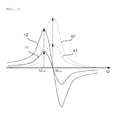
- FIG. 2 is a graph for explaining the appearance of how the refractive index is changed in the vicinity of anti-stokes frequency due to coherent anti-stokes Raman scattering.
- ⁇ p represents frequency of pump light
- the change in absorptance accompanies the change in refractive index.
- the change in absorptance and the change in absorptance depend on the following equation that is referred to as Kramer-Kronig relation.
- ⁇ ⁇ n ⁇ c ⁇ ⁇ P ⁇ ⁇ 0 ⁇ ⁇ ⁇ ⁇ ⁇ d ⁇ ⁇ ⁇ 2 - ⁇ 2
- c is any constant and P means Cauchy principal value.
- Refractive index n ( ⁇ ) according to the relation between the absorptance and the refractive index is shown in FIG. 2 . As shown in FIG. 2 , the refractive index is changed most in the vicinity of ⁇ as .
- FIG. 3 is a graph showing in more detail a change in absorptance and refractive index.
- a refractive index graph n1 corresponding to an absorptance graph ⁇ 1 is shown in FIG. 3 .
- the most change in refractive index is at lower or higher frequency by a predetermined frequency in the vicinity of ⁇ as .
- the change in refractive index becomes larger in the vicinity of ⁇ as .
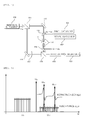
- FIG. 4 is a diagram showing a configuration of an apparatus for obtaining images using the coherent anti-stokes Raman scattering according to one embodiment of the present invention.
- the apparatus for obtaining images according to the embodiment includes a pump light source 401 and a stokes light source 402 that generate pump light and stokes light irradiated on the sample to generate anti-stokes light having anti-stokes frequency, a reference light source 410 that generates reference light, and as shown in FIG. 4 , an image obtaining unit that obtains images of the sample using the change in phase of the reference light due to the change in refractive index of the sample in the vicinity of the anti-stroke frequency.
- a pulse type laser light source is used as the pump light source 401 and the stokes light source 402 .
- the frequency ⁇ ref of the reference light has higher or lower frequency by a predetermined magnitude than the anti-stokes frequency ⁇ as .
- the frequency corresponding to the point where the change in refractive index is largest that is, lower frequency by the predetermined magnitude than ⁇ as as the frequency of the reference light ⁇ ref .
- the pump light source 401 and the stokes light source 402 each generates the pump light at the frequency ⁇ p and the stokes light at the frequency ⁇ s and the pump light and the stokes light are reflected from a first dichroic reflector 413 and are irradiated on the sample S.
- the anti-stokes light is generated due to the coherent anti-stokes Raman scattering.
- the pump light and the stokes light are reflected from a second dichroic reflector 415 and emitted to the outside.
- the first dichroic reflector 413 and the second dichroic reflector 415 perform a function of filtering the pump light and the stokes light by reflecting the pump light at the frequency ⁇ p and the stokes light at the frequency ⁇ s and passing through the reference light at the frequency ⁇ ref .
- the reference light source 410 generates the reference light having the frequency ⁇ ref .
- the reference light is split into a first path passing through the sample S and a second path not passing through the sample S by a first optical splitter 411.
- the reference light split into the first path is reflected from the first reflector 412 and passes through the first dichroic reflector 413 and then passes through the sample S.
- the reference light can be magnified by a microscope object lens 414.
- the reference light passing through the sample is subjected to the phase change. This reference light is incident to a second optical splitter 418.
- variable wavelength plate 417 may be disposed at the path of the reference light.
- the detector 419 detects signals due to the interference phenomenon and the detected signal is transferred to an imaging unit 430.
- the imaging unit 430 analyzes the detected signal, images it, and outputs it through a display (not shown), etc.
- each component for example, a transfer device, which transfers the first optical splitter 411, the first and second reflectors 412 and 416, and the like, may be installed.
- a pulse type laser light source as the pump light source 401 is used and a broadband light source having a broad frequency band instead of a single frequency of a pulse type laser light source as the stokes light source 402, for example, an LED light source is used.
- FIG. 5 is a graph showing appearance, absorptance, and refractive index of anti-stokes light generated when a frequency band of stokes light is broad.
- the anti-stokes light has a sufficient broad frequency band
- the coherent anti-stokes Raman scattering is generated at a plurality of frequencies to generate the anti-stokes light having a plurality of anti-stokes frequencies ⁇ asi and ⁇ as2 . Therefore, the images of the sample can be obtained using the change in phase of the reference light due to the change in the refractive index of the sample at each frequency.
- the reference light also uses the reference light having the broad frequency band.
- the detector 419 a device capable of detecting the signals generated due to the interference phenomenon at several frequency bands is used. For example, an arrayed detector or a CCD array, etc., may be used.
- FIG. 6 is a graph for explaining an embodiment using two reference lights, that is, two reference lights each having a lower frequency ⁇ ref1 by the predetermined magnitude than the anti-stokes frequency ⁇ as and higher frequency ⁇ ref2 by the predetermined magnitude than the anti-stokes frequency ⁇ as together as another embodiment of the present invention.
- the sign of the refractive index at ⁇ ref1 and the refractive index at ⁇ ref2 is opposite to each other based on the refractive index at the anti-stokes frequency ⁇ as . Therefore, the noise at the time of measuring the change in strength of the light source, etc. can be reduced by using the difference between the refractive indexes at two frequencies.
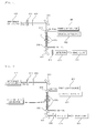
- FIG. 7 is a diagram showing a configuration of an apparatus for obtaining images using coherent anti-stokes Raman scattering according to another embodiment of the present invention and is a configuration diagram showing an embodiment using two reference lights each having two frequencies of ⁇ ref1 and ⁇ ref2 .
- an apparatus for obtaining images includes a pump light source 701 and a stokes light source 702 that generate pump light and stokes light irradiated on the sample to generate anti-stokes light having anti-stokes frequency, a first reference light source 703 and a second reference light source 704 that generate first reference light at ⁇ ref1 and second reference light at ⁇ ref2 , a unit that splits a path into the first path passing through the sample S and the second path not passing through the sample S and propagates each of the first and second reference lights to the first and second paths and an image obtaining unit that obtain the images of the sample using a phase difference between the first reference light passing through the first path and the first reference light passing through the second path and a phase difference between the second reference light passing through the first path and the second reference light passing through the second path together.
- the pump light source 701 and the stokes light source 702 each generates the pump light at the frequency ⁇ p and the stokes light at the frequency ⁇ s and the pump light and the stokes light are reflected from a second dichroic reflector 713 and are irradiated on the sample S.
- the anti-stroke light is generated due to the coherent anti-stokes Raman scattering.
- the pump light and the stokes light are reflected from a third dichroic reflector 715 and are discharged to the outside.
- the second dichroic reflector 713 and the third dichroic reflector 715 reflect the pump light at the frequency ⁇ p and the stokes light at the frequency ⁇ s while performing as a filter for the pump light and the stokes light by passing through the pump light at the frequency ⁇ ref1 and the stokes light at the frequency ⁇ ref2 .
- the first reference light source 703 generates the first reference light having the frequency ⁇ ref1 .
- the first reference light is reflected from the first reflector 705 and the first dichroic reflector 706 and is incident on the first splitter 711, which is in turn split into two paths, where the first path passes through the sample S and the second path does not pass through the sample S.
- the second reference light source 704 generates the second reference light having the frequency ⁇ ref2 .
- the second reference light passes through the first dichroic reflector 706 and is incident on the first splitter 711, which is in turn split into two paths, where the first path passes through the sample S and the second path does not pass through the sample S like the first reference light.
- the first reference light and the second reference light split into the first path are reflected from the second reflector 712 and passes through the sample S via the second dichroic reflector 713. At this time, the reference light can be magnified by a microscope object lens 714.
- the reference light passing through the sample is subjected to the phase change.
- the first reference light and the second reference light passing through the sample are incident to a second optical splitter 718.
- the first reference light and the second reference light split into the second path are reflected from a third reflector 716 and are incident to the second optical splitter 718.
- a variable wavelength plate 717 may be disposed in the paths.
- the third dichroic reflector 719 passes through the light at the frequency ⁇ ref1 and reflects the light at the frequency ⁇ ref1 . Therefore, the first detector 721 detects the signals due to the interference phenomenon at the frequency ⁇ ref1 area and the second detector 722 detects the signals due to the interference phenomenon at the frequency ⁇ ref2 area reflected from a fourth reflector 720.
- the signals detected in each of the first detector 721 and the second detector 722 are input to an imaging unit 730.
- the imaging unit 730 images a difference between the signal detected in the first detector 721 and the signal detected in the second detector 722 and outputs it through the display (not shown) etc.
- FIG. 8 is a diagram showing a configuration of an apparatus for obtaining images using coherent anti-stokes Raman scattering according to still another embodiment of the present invention.
- the change in birefringence is differently displayed according to directivity of the refractive index.
- the images of the sample are obtained using the change in birefringence.
- an apparatus for obtaining images includes a pump light source 801 and a stokes light source 802 that generate pump light and stokes light irradiated on the sample to generate anti-stokes light having anti-stokes frequency, a reference light source 810 that generates reference light having higher or lower frequency by a predetermined magnitude than the anti-stroke frequency, and as shown in FIG. 8 , an image obtaining unit that obtains images of the sample S using the change in polarizing state of the reference light due to the change in birefringence of the sample.
- a pulse type laser light source is used as the pump light source 801 and the stokes light source 802 .
- the pump light source 801 and the stokes light source 802 each generates the pump light at the frequency ⁇ p and the stokes light at the frequency ⁇ s and the pump light and the stokes light are reflected from a first dichroic reflector 814 and are irradiated on the sample S.
- the anti-stokes light is generated due to the coherent anti-stokes Raman scattering.
- the pump light and the stokes light are reflected from a second dichroic reflector 816 and emitted to the outside.
- the first dichroic reflector 814 and the second dichroic reflector 816 performs a function of filtering the pump light and the stokes light by reflecting the pump light at the frequency ⁇ p and the stokes light at the frequency ⁇ s and passing through the reference light at the frequency ⁇ ref .
- the reference light source 810 generates the reference light having the frequency ⁇ ref .
- the reference light becomes light polarized in an optical axis direction owned by a first polarizer 811 after passing through the first polarizer 811.
- the polarized reference light passes through a variable wavelength plate 812 and then reflected from the first reflector 813, which is in turn irradiated on the sample S.
- the reference light can be magnified by a microscope object lens 815.
- the reference light passes through the sample S and the reflected from the second reflector 817.
- the reference light is incident on an optical axis in a different direction from the first polarizer 811, for example, a second polarizer 818 having the optical axis having a difference by 90°.
- a detector 819 detects the reference light passing through the second polarizer 818 and an imaging unit 830 analyzes polarizing property of the reference light before passing through the sample S and polarizing property of the reference light after passing through the sample S, measure the birefringence, images it, and outputs it through the display (not shown) etc.
- FIG. 9 is a diagram showing a configuration of an apparatus for obtaining images using coherent anti-stokes Raman scattering according to still another embodiment of the present invention and shows an embodiment further including an electromagnetic generating unit 840 that applies electric field or magnetic field to the sample S in the apparatus for obtaining images.
- an electromagnetic generating unit 840 that applies electric field or magnetic field to the sample S in the apparatus for obtaining images.
- the coherent anti-stroke Raman scattering effect can be increased or reduced. Therefore, the change in birefringence due to the coherent anti-stokes Raman scattering can be controlled.
- the images of the sample can be obtained by using the change in the refractive index or the change in birefringence in the vicinity of the anti-stokes frequency owned by the anti-stokes light without directly measuring the signal strength of the anti-stokes light generated by the coherent anti-stokes Raman scattering. Therefore, the present invention can implement the apparatus for obtaining images using coherent anti-stokes Raman scattering that is not affected by the non-resonant background signal phenomenon and has strong resistance against noise even if the signal is weak and has excellent sensitivity and resolution since the change in the refractive index has nothing to do with the signal strength
Landscapes
- Physics & Mathematics (AREA)
- Health & Medical Sciences (AREA)
- Spectroscopy & Molecular Physics (AREA)
- General Physics & Mathematics (AREA)
- Biochemistry (AREA)
- Analytical Chemistry (AREA)
- Chemical & Material Sciences (AREA)
- General Health & Medical Sciences (AREA)
- Life Sciences & Earth Sciences (AREA)
- Immunology (AREA)
- Pathology (AREA)
- Nuclear Medicine, Radiotherapy & Molecular Imaging (AREA)
- Investigating, Analyzing Materials By Fluorescence Or Luminescence (AREA)
- Microscoopes, Condenser (AREA)
Applications Claiming Priority (1)
| Application Number | Priority Date | Filing Date | Title |
|---|---|---|---|
| KR1020080017799A KR100929202B1 (ko) | 2008-02-27 | 2008-02-27 | 가간섭성 반스토크스 라만 산란을 이용한 영상 획득 장치및 방법 |
Publications (2)
| Publication Number | Publication Date |
|---|---|
| EP2096430A2 true EP2096430A2 (de) | 2009-09-02 |
| EP2096430A3 EP2096430A3 (de) | 2013-02-20 |
Family
ID=40589988
Family Applications (1)
| Application Number | Title | Priority Date | Filing Date |
|---|---|---|---|
| EP09153244A Withdrawn EP2096430A3 (de) | 2008-02-27 | 2009-02-19 | Vorrichtung und Verfahren zur Bildgebung unter Verwendung kohärenter Anti-Stokes-Raman-Streuung |
Country Status (4)
| Country | Link |
|---|---|
| US (1) | US8064064B2 (de) |
| EP (1) | EP2096430A3 (de) |
| JP (1) | JP2009204613A (de) |
| KR (1) | KR100929202B1 (de) |
Cited By (2)
| Publication number | Priority date | Publication date | Assignee | Title |
|---|---|---|---|---|
| WO2011089119A1 (fr) * | 2010-01-22 | 2011-07-28 | Centre National De La Recherche Scientifique - Cnrs | Methode pour la detection d'un signal optique non lineaire resonant et dispositif pour la mise en oeuvre de ladite methode |
| WO2020077735A1 (zh) * | 2018-10-19 | 2020-04-23 | 清华大学 | 一种双光频梳光谱聚焦相干反斯托克斯拉曼光谱探测系统 |
Families Citing this family (7)
| Publication number | Priority date | Publication date | Assignee | Title |
|---|---|---|---|---|
| US9833145B2 (en) | 2010-08-11 | 2017-12-05 | Snu R&Db Foundation | Method for simultaneously detecting fluorescence and raman signals for multiple fluorescence and raman signal targets, and medical imaging device for simultaneously detecting multiple targets using the method |
| KR101207695B1 (ko) * | 2010-08-11 | 2012-12-03 | 서울대학교산학협력단 | 형광 및 라만 신호 표적에 대한 형광 및 라만 신호 동시검출방법 및 이를 이용한 표적 동시검출용 의학영상장치 |
| JP5736325B2 (ja) * | 2012-02-21 | 2015-06-17 | 株式会社日立製作所 | 光学装置 |
| WO2014162744A1 (ja) * | 2013-04-05 | 2014-10-09 | 株式会社ニコン | 細胞観察方法、細胞観察装置、細胞観察プログラム、細胞シート製造方法および細胞シート製造装置 |
| KR102129382B1 (ko) * | 2018-12-17 | 2020-07-02 | 주식회사 토모큐브 | 간섭 패턴에서 파동의 위상 정보 추출 방법 및 장치 |
| KR102268995B1 (ko) * | 2019-05-14 | 2021-06-25 | 고려대학교 산학협력단 | 선택적 가간섭성 반스톡스 라만산란 신호 억제 방법 및 장치 |
| KR102455161B1 (ko) * | 2021-04-23 | 2022-10-18 | 대전대학교 산학협력단 | 전기장과 자기장 및 led를 이용한 분광 장치 |
Family Cites Families (12)
| Publication number | Priority date | Publication date | Assignee | Title |
|---|---|---|---|---|
| US4405237A (en) * | 1981-02-04 | 1983-09-20 | The United States Of America As Represented By The Secretary Of The Navy | Coherent anti-Stokes Raman device |
| JPS639828A (ja) * | 1986-07-01 | 1988-01-16 | Hitachi Ltd | カ−ス光学装置 |
| JPH10115573A (ja) * | 1996-10-11 | 1998-05-06 | Hitachi Ltd | 3次非線形感受率測定方法及び装置 |
| JP4854878B2 (ja) * | 2001-07-03 | 2012-01-18 | オリンパス株式会社 | レーザー顕微鏡 |
| JP3949600B2 (ja) * | 2003-03-28 | 2007-07-25 | 株式会社神戸製鋼所 | 光熱変換測定装置及びその方法 |
| US7388668B2 (en) * | 2004-06-09 | 2008-06-17 | President & Fellows Of Harvard College | Phase sensitive heterodyne coherent anti-Stokes Raman scattering micro-spectroscopy and microscopy |
| US7586618B2 (en) * | 2005-02-28 | 2009-09-08 | The Board Of Trustees Of The University Of Illinois | Distinguishing non-resonant four-wave-mixing noise in coherent stokes and anti-stokes Raman scattering |
| JP4290142B2 (ja) * | 2005-05-13 | 2009-07-01 | 株式会社神戸製鋼所 | 光熱変換測定装置及びその方法 |
| DE102005044422A1 (de) * | 2005-09-16 | 2007-03-29 | Carl Zeiss Jena Gmbh | Kohärente anti-Stokes'sche Ramanstreuungs-(CARS)-Mikroskopie |
| US7573577B2 (en) * | 2005-10-21 | 2009-08-11 | Southwest Research Institute | Spatial heterodyne wide-field Coherent Anti-Stokes Raman spectromicroscopy |
| KR100826593B1 (ko) * | 2007-02-13 | 2008-04-30 | 한국표준과학연구원 | 연속신호생성 방식 비선형 간섭성 반스톡스 라만산란이미징 장치 |
| KR100860947B1 (ko) * | 2007-06-08 | 2008-09-30 | 한국표준과학연구원 | 적외선 비선형 분자진동 분광 이미징 장치 |
-
2008
- 2008-02-27 KR KR1020080017799A patent/KR100929202B1/ko not_active IP Right Cessation
-
2009
- 2009-02-12 US US12/370,581 patent/US8064064B2/en not_active Expired - Fee Related
- 2009-02-19 EP EP09153244A patent/EP2096430A3/de not_active Withdrawn
- 2009-02-27 JP JP2009045250A patent/JP2009204613A/ja active Pending
Non-Patent Citations (2)
| Title |
|---|
| A. ZUMBUSCH; G. R. HOLTOM; X. S. XIE: "Three-dimensional vibrational imaging by coherent anti-Stokes Raman scattering", PHYS. REV. LETT., vol. 82, 1999, pages 4142 - 4145 |
| M. D. DUNCAN; J. REINTJES; T. J. MANUCCIA: "Scanning coherent anti-Stokes Raman microscope", OPT. LETT., vol. 7, 1982, pages 350 - 352 |
Cited By (4)
| Publication number | Priority date | Publication date | Assignee | Title |
|---|---|---|---|---|
| WO2011089119A1 (fr) * | 2010-01-22 | 2011-07-28 | Centre National De La Recherche Scientifique - Cnrs | Methode pour la detection d'un signal optique non lineaire resonant et dispositif pour la mise en oeuvre de ladite methode |
| FR2955663A1 (fr) * | 2010-01-22 | 2011-07-29 | Centre Nat Recherche | Methode pour la detection d'un signal optique non lineaire resonant et dispositif pour la mise en oeuvre de ladite methode |
| US8804117B2 (en) | 2010-01-22 | 2014-08-12 | Centre National De La Recherche Scientifique-Cnrs | Method for detecting a resonant nonlinear optical signal and device for implementing said method |
| WO2020077735A1 (zh) * | 2018-10-19 | 2020-04-23 | 清华大学 | 一种双光频梳光谱聚焦相干反斯托克斯拉曼光谱探测系统 |
Also Published As
| Publication number | Publication date |
|---|---|
| US20090213370A1 (en) | 2009-08-27 |
| EP2096430A3 (de) | 2013-02-20 |
| JP2009204613A (ja) | 2009-09-10 |
| KR20090092512A (ko) | 2009-09-01 |
| KR100929202B1 (ko) | 2009-12-01 |
| US8064064B2 (en) | 2011-11-22 |
Similar Documents
| Publication | Publication Date | Title |
|---|---|---|
| US8064064B2 (en) | Apparatus and method for obtaining images using coherent anti-stokes Raman scattering | |
| US7582870B2 (en) | Imaging apparatus for IR four-wave mixing polarization microscopy | |
| US7667848B2 (en) | Imaging apparatus for infrared rays nonlinear molecular vibrational microscopy | |
| US6809814B2 (en) | System and method for epi-detected coherent anti-stokes raman scattering microscopy | |
| JP5329449B2 (ja) | 顕微鏡イメージングを実行する方法 | |
| WO2014125729A1 (ja) | 測定装置及び測定方法 | |
| US9625389B2 (en) | Light measuring device and light measuring method | |
| US8804117B2 (en) | Method for detecting a resonant nonlinear optical signal and device for implementing said method | |
| EP2601514B1 (de) | Verfahren und vorrichtung für nichtresonante hintergrundreduktion in der kohärenten anti-stokes-ramanstreuungspektroskopie (cars-spektroskopie) | |
| JP2009192524A5 (de) | ||
| CN106990095B (zh) | 反射式共焦cars显微光谱测试方法与装置 | |
| WO2015025389A1 (ja) | Cars顕微鏡 | |
| US7787118B2 (en) | Apparatus and method for obtaining spectral information | |
| WO2016143084A1 (ja) | 光計測装置及び光計測方法 | |
| Ito et al. | Invited article: Spectral focusing with asymmetric pulses for high-contrast pump–probe stimulated raman scattering microscopy | |
| JP2008541125A (ja) | 分光方法 | |
| US9097674B2 (en) | Method for detecting a resonant nonlinear optical signal and device for implementing said method | |
| KR100784901B1 (ko) | 제거형 가간섭성 반스토크스 라만 분광법을 이용한 광학장치 | |
| CN108982365B (zh) | 一种光场行波腔增强表面等离子体共振传感装置 | |
| JP6923161B2 (ja) | 試料分析装置 | |
| RECCHIA | A multimodal nonlinear optical microscope for biological applications |
Legal Events
| Date | Code | Title | Description |
|---|---|---|---|
| PUAI | Public reference made under article 153(3) epc to a published international application that has entered the european phase |
Free format text: ORIGINAL CODE: 0009012 |
|
| 17P | Request for examination filed |
Effective date: 20090219 |
|
| AK | Designated contracting states |
Kind code of ref document: A2 Designated state(s): AT BE BG CH CY CZ DE DK EE ES FI FR GB GR HR HU IE IS IT LI LT LU LV MC MK MT NL NO PL PT RO SE SI SK TR |
|
| AX | Request for extension of the european patent |
Extension state: AL BA RS |
|
| PUAL | Search report despatched |
Free format text: ORIGINAL CODE: 0009013 |
|
| AK | Designated contracting states |
Kind code of ref document: A3 Designated state(s): AT BE BG CH CY CZ DE DK EE ES FI FR GB GR HR HU IE IS IT LI LT LU LV MC MK MT NL NO PL PT RO SE SI SK TR |
|
| AX | Request for extension of the european patent |
Extension state: AL BA RS |
|
| RIC1 | Information provided on ipc code assigned before grant |
Ipc: G01J 3/44 20060101ALI20130115BHEP Ipc: G01N 21/65 20060101AFI20130115BHEP |
|
| AKX | Designation fees paid |
Designated state(s): DE FR GB |
|
| RIC1 | Information provided on ipc code assigned before grant |
Ipc: G01N 21/65 20060101AFI20131010BHEP Ipc: G01J 3/44 20060101ALI20131010BHEP |
|
| GRAP | Despatch of communication of intention to grant a patent |
Free format text: ORIGINAL CODE: EPIDOSNIGR1 |
|
| INTG | Intention to grant announced |
Effective date: 20131205 |
|
| STAA | Information on the status of an ep patent application or granted ep patent |
Free format text: STATUS: THE APPLICATION IS DEEMED TO BE WITHDRAWN |
|
| 18D | Application deemed to be withdrawn |
Effective date: 20140416 |