EP2096031B1 - Helicopter equipped with a plurality of lifting elements for controlling the angle of attack of its blades - Google Patents
Helicopter equipped with a plurality of lifting elements for controlling the angle of attack of its blades Download PDFInfo
- Publication number
- EP2096031B1 EP2096031B1 EP09002430A EP09002430A EP2096031B1 EP 2096031 B1 EP2096031 B1 EP 2096031B1 EP 09002430 A EP09002430 A EP 09002430A EP 09002430 A EP09002430 A EP 09002430A EP 2096031 B1 EP2096031 B1 EP 2096031B1
- Authority
- EP
- European Patent Office
- Prior art keywords
- lift element
- blade
- lift
- pitch
- rotor
- Prior art date
- Legal status (The legal status is an assumption and is not a legal conclusion. Google has not performed a legal analysis and makes no representation as to the accuracy of the status listed.)
- Active
Links
- 238000000034 method Methods 0.000 claims description 7
- 230000005540 biological transmission Effects 0.000 claims description 2
- 125000004122 cyclic group Chemical group 0.000 description 14
- 230000008859 change Effects 0.000 description 7
- 230000008878 coupling Effects 0.000 description 6
- 238000010168 coupling process Methods 0.000 description 6
- 238000005859 coupling reaction Methods 0.000 description 6
- 238000004873 anchoring Methods 0.000 description 5
- 230000000694 effects Effects 0.000 description 3
- 230000008901 benefit Effects 0.000 description 2
- 238000013016 damping Methods 0.000 description 2
- 238000002592 echocardiography Methods 0.000 description 2
- 230000005484 gravity Effects 0.000 description 2
- 230000004044 response Effects 0.000 description 2
- 238000010009 beating Methods 0.000 description 1
- 230000000593 degrading effect Effects 0.000 description 1
- 238000006073 displacement reaction Methods 0.000 description 1
- 229920001971 elastomer Polymers 0.000 description 1
- 239000000806 elastomer Substances 0.000 description 1
- 230000005611 electricity Effects 0.000 description 1
- 230000006872 improvement Effects 0.000 description 1
- 230000004048 modification Effects 0.000 description 1
- 238000012986 modification Methods 0.000 description 1
- 230000035939 shock Effects 0.000 description 1
- 230000000087 stabilizing effect Effects 0.000 description 1
- 238000011144 upstream manufacturing Methods 0.000 description 1
Images


Classifications
-
- B—PERFORMING OPERATIONS; TRANSPORTING
- B64—AIRCRAFT; AVIATION; COSMONAUTICS
- B64C—AEROPLANES; HELICOPTERS
- B64C27/00—Rotorcraft; Rotors peculiar thereto
- B64C27/54—Mechanisms for controlling blade adjustment or movement relative to rotor head, e.g. lag-lead movement
- B64C27/58—Transmitting means, e.g. interrelated with initiating means or means acting on blades
- B64C27/59—Transmitting means, e.g. interrelated with initiating means or means acting on blades mechanical
- B64C27/605—Transmitting means, e.g. interrelated with initiating means or means acting on blades mechanical including swash plate, spider or cam mechanisms
Definitions
- the present invention relates to a helicopter having a plurality of lift elements for controlling the aerodynamic incidence of its blades. As a result, this invention is in the restricted technical field of helicopter blade pitch controls.
- a helicopter commonly comprises a main lift and propulsion rotor provided with a plurality of blades.
- the blades of the main rotor describe a very open cone, called "rotor cone" by the skilled person, the plane of rotation is perpendicular to the general lift generated by the main rotor.
- This general lift of the main rotor can then be decomposed into a vertical lift force and a horizontal force which ensures the translation of the helicopter.
- the main rotor ensures the lift and propulsion of the helicopter.
- a pilot can precisely steer the helicopter.
- the helicopter is provided with specific means for varying the pitch of each blade, and therefore the aerodynamic incidence of each blade relative to the incident air flow traversed by the blade.
- the lift it generates is modified, which causes the blade to beat.
- the pilot of the helicopter In order to control the overall lift of the rotor, in intensity and direction, the pilot of the helicopter therefore generally acts on the value of the pitch angle of each blade by controlling a rotation of the blade about its longitudinal axis of pitch .
- this pilot when the pilot orders a collective pitch variation, that is to say an identical pitch variation of all the blades, this pilot varies the intensity of the general lift of the main rotor so as to control the altitude and speed of the helicopter.
- the pitch of a blade varies according to its azimuth and passes during a complete revolution from a maximum value to a minimum value obtained in opposite azimuths.
- the cyclic variation of the pitch of the blades is at the origin of a cyclic variation of the lift of the blades and thus of the inclination of the rotor cone.
- the pilot controls the attitude of the aircraft and its translation.
- a helicopter rotor is provided with two blades each secured to a sleeve fixed to a hub.
- the pilot controls the collective pitch of the blades using a lever acting on a rod housed inside the rotor mast.
- This rod echoes its movement on a first and a second connecting rods fixed to the hub.
- the driver By operating the control lever collective pitch, the driver causes a translation of said rod which generates a rotation of the hub and therefore the blades around a pitch variation axis.
- the hub is secured to a first and a second lift elements arranged in the plane of the blades via a first and second connecting shafts rigidly interconnected, the longitudinal axis of the lift elements being perpendicular to the longitudinal axes of the blades.
- These lift elements are called “pallet" by the skilled person.
- Each link shaft is further connected to a control plate, called a swashplate, via a compass. More specifically, the swashplate having a turntable and a non-rotating plate, the compasses are fixed on the turntable of the swashplate.
- the non-rotating plate has a bar which the driver can seize.
- the pilot maneuvers the bar to tilt the non-rotating plate, and consequently the turntable.
- the inclination of the turntable is then passed on the first and second linkage trees via the compass which allows to change the pitch of the lift elements.
- the lift generated by these lift elements therefore varies which causes a beat of the latter and consequently a tilting of the hub.
- This first device is relatively simple but imposes the presence of a cyclic plateau penalizing from a mass and aerodynamic point of view.
- the lift elements are supposed to cyclically vary the pitch of the blades. However, this is not really the case, at least in the strict sense, insofar as the two lift elements act together on the hub and therefore on both blades simultaneously and identically.
- the lift elements are each equipped with a shutter.
- the compasses arranged on the turntable do not cause the variation of pitch of the lift elements but the inclination of the flaps with respect to these lift elements.
- the effort to be exerted by the pilot to vary the pitch of the blades is then reduced compared to the first device insofar as the bearing surface of the flap is small compared to the bearing surface of the lift element.
- first and second devices are not a priori applicable on a helicopter having more than two blades in that the hub can rotate around a single axis during the cyclic pitch variation.
- the pilot's collective and cyclic pitch controls are connected to three servocontrols, via connecting rods and combiners or electrical controls, secured to the non-rotating plate of a swashplate.
- the swashplate is mechanically linked to each blade by a pitch control rod.
- the pitch control rods are then all moved the same distance which implies that the pitch of all blades varies the same angle.
- the pilot orders the movement of a single servo control for example.
- the swashplate moves vertically but then tilts relative to the rotor mast.
- Each pitch control rod moves in a direction and a value of its own and the same for the pitch of the associated blade.
- the pitch control is in some way individualized, unlike the first and second devices, since each blade is controlled by its own pitch control rod.
- This third device is very effective which explains its generalization. Nevertheless, the efforts to be made to maneuver the blades being important, particularly on large helicopters, the servocontrols and the swashplate have masses and large dimensions which is very penalizing.
- the present invention is then intended to provide a helicopter to overcome the limitations mentioned above.
- the object of the invention is to obtain a device and method for changing the pitch of the main rotor blades of a helicopter which is both light and efficient by allowing perfect control of the collective and cyclic pitch of the blades. regardless of the number of rotor blades.
- a helicopter is provided with a main rotor comprising at least two blades, each blade being provided with a means of attachment to a hub of the rotor.
- the means for fixing the blade to the hub may consist of a sleeve secured by conventional means or a sleeve integral with the blade for example.
- This helicopter is remarkable in that it is provided with a blade lift element, each lifting element being mechanically connected to a single blade to vary the pitch of said single blade to which the lift element is connected.
- each blade is controlled by a lift element linked to the anchoring of the blade. Unlike the first and second devices of the prior art, each blade is well controlled by its own lift element.
- Each lift element is then managed independently, functionally and mechanically, so as to individually vary the pitch of a single blade.
- the system is operational regardless of the number of blades in that the lift elements do not necessarily have a 90 ° angulation with the blades or be in the same plane as the blades.
- the invention is applicable to a helicopter having at least two blades and not only two blades which is a definite advantage.
- the invention may include one or more of the following additional features.
- each lift element being mechanically connected to a blade, each lift element is advantageously rotationally integral with the blade to which it is mechanically linked around a first longitudinal axis of pitch variation of the blade.
- the lift element thus directly controls the pitch of the blade, and not via the hub of the rotor, for example.
- each lift element is mechanically connected to a single blade by a mechanical connection independent of the hub of the rotor, the mechanical connection advantageously linking the lift element to a zone of attachment of the blade to the hub, that is to say either by means of attachment of the blade or to a section of the blade itself.
- the mechanical connection does not encompass the hub of the rotor, unlike the first and second devices of the prior art for which each lift element is mechanically connected to the hub and causes the tilting of the hub.
- each lift element being mechanically connected to a single blade by a mechanical connection
- this mechanical connection optionally comprises an angle of which a first end is secured to the blade attachment zone, more precisely by means of fixing the blade. to the hub or a section of the blade itself.
- each lift element is secured in rotation around the axis of flapping of said lift element at a second end of the corresponding angle via a hinge allowing the lifting element to lift. rotating about a second longitudinal axis of pitch variation of the lift element.
- a second end of each bracket is fixed by an intermediate link to the corresponding lift element, specifically to the hinge allowing the lift element to perform a rotary movement around a second longitudinal axis of pitch variation of the lift element.
- the articulation of the lift element is fixed to the intermediate link.
- each lift element is then provided with a support means and a fastener with three degrees of freedom, the support means being secured to the corresponding lift element, the attachment with three degrees of freedom being fixed a rotating unit comprising the mast of the rotor and its hub and the means for attaching the blade to the hub of the rotor.
- the support means then passes through the second end of the angle so as to allow the lifting element rotating about its second longitudinal pitch axis and rotating the angle about its beat axis.
- the three-degree of freedom fastener a spherical abutment for example, is sized to minimize the distance separating the beat axis of the lift element from the first longitudinal axis of pitch variation of the corresponding blade. so that said beat axis and said first longitudinal axis are substantially merged.
- the fastener with three degrees of freedom will therefore be fixed to the hub of the rotor while according to the third variant it will be fixed to the mast of the rotor, or to a member extending said mast.
- the pilot of the helicopter will begin by modifying the pitch of the lift element to modify the lift generated by this element. sustainer. This modification causes the lifting element to bounce up or down as the case may be so as to rotate the blade to which it is mechanically linked around its first longitudinal axis.
- the invention remains surprisingly advantageous compared to the third known device.
- the blades being contained in a first plane when they do not beat, the lift elements mechanically linked to said blades being contained in a second plane when they do not beat, the first and second shots are confused.
- the first and second pitch variation axes are therefore arranged in the same plane.
- the first and second planes are parallel to one another, one plane lying on top of the other.
- the first variant is interesting because of its simplicity. Nevertheless, the second and third variants are optimized according to the need.
- the second variant consists in slightly shifting, by the order of magnitude of the thickness of the lift element, the first and second planes, by inclining the angle connecting the lift element to the attachment zone of the corresponding blade, in order to cancel the effects of gravity on the lift elements.
- the weight of the lift elements tends to make them beat in the direction of gravity. This beat is able to cause a rotation of the blades that would not have been required by the pilot.
- the third variant consists in substantially shifting, by the order of magnitude of the rope of the lift elements, the first and second planes using the intermediate link to extend the application of the invention to a rotor having any what number of blades.
- this third variant makes it possible to optimize the aerodynamic characteristics of the rotor by moving the lift elements away from the disturbed zone of the rotor head.
- the rotor may optionally include a stop means for limiting the beat of each lift element.
- This feature ensures a certain security to the system by preventing the beat of the lift elements is too important and therefore limiting the pitch of the blades.
- This abutment means is provided with an upper plate which at least partially covers an upper part of the hub of the rotor, this upper part being located on the side of the hub opposite the fuselage of the helicopter.
- the stop means comprises a limit limiter per lift element.
- Each stroke limiter a jack for example, is then arranged between the upper plate and each articulation to limit the beat of each lift element.
- this abutment means is provided with a lower plate which at least partially covers a lower part of the hub of the rotor, the lower part being located on the side of the hub facing the fuselage of the helicopter .
- the beat of the lift element, or its articulation to the mechanical linkage linking it to a blade, is then limited by the lower or upper plates. In case of excessive beat, the lift element or its articulation comes into contact with the upper or lower plate which stops its movement.
- the upper and lower plates may be locally provided with damping means to avoid degrading the lift element or its articulation when the latter are in abutment.
- the helicopter has a main link per lift element so that the pilot can adjust the pitch of each lift element.
- Each main link is then articulated on a remote anchor point of a single lift element to control the pitch of the lift element on which the main link is articulated.
- anchor point is offset with respect to the second longitudinal axis of pitch variation of the element levitateur to control the rotation of this levator element.
- the main rotor comprising a cyclic pitch control plate provided with a turntable and a non-rotating plate, each main link is articulated on the turntable, and of course on the point of remote anchoring of the lift element.
- the pilot controls the swashplate, via servocontrols, for example, to vary the pitch of the lift elements and consequently the blades.
- the servocontrols of the invention will have reduced dimensions and weight, compared to the servocontrols implemented by the third known device.
- the main rotor comprising a cyclic pitch control plate provided with a turntable and a non-rotating plate, said main link is articulated on a first branch of a deflection means , L-shaped for example, secured to the hub of the rotor.
- a second branch of the return means is then connected to the turntable by a secondary link, this secondary link being de facto articulated on the turntable.
- main link is articulated either on the branch of the return means closest to the fuselage of the helicopter, or on the branch of the return means furthest from the fuselage.
- the turntable is not connected directly to the main link of each lift element.
- This coupling between the pitch and the beat of the lift element has a stabilizing effect on the response of the lift element but it reduces the effectiveness of the system since it limits the response to a control order.
- the anchor point of the main link on the lift element can be offset at the rear of the latter, near its trailing edge, so to obtain a pitch / beat coupling tending to increase the beat when the step increases.
- Such coupling tends to increase the effectiveness of the device but the latter may become unstable if the coupling is excessive.
- the pitch of the lift element remains constant in case of a beat.
- this second embodiment makes it possible to eliminate the pitch / beat coupling of the lift element.
- the helicopter comprises an actuator, of piezoelectric type for example, by main link.
- Each main link is then controlled by an actuator attached to the hub or to the rotor mast.
- This actuator can be electrically powered via an electrical collector arranged on a rotating mast of the rotor. Electrical energy being conveyed by means of electric cables from a generator installed in the fuselage of the helicopter, the function of the collector is to transfer energy from the fixed reference of the fuselage towards the rotating mark of the rotor.
- stator of the electric generator is placed inside the mast of the rotor, the stator being moreover rigidly connected to the bottom of the main gearbox.
- the rotating member of the generator is then rigidly connected to the rotor mast.
- the rotation of the rotor mast allows the generator to generate the electricity necessary for the proper functioning of the actuators of the lift elements.
- Pilot flight controls send an electrical signal to an actuator that pushes or pulls a main link to vary the pitch of the associated lift element.
- These commands can be transmitted by a means of wireless transmission by electromagnetic waves in the radio range, infrared, or by microwave.
- This third embodiment therefore does not require the implementation of a swashplate.
- the present invention also relates to the method implemented by the claimed helicopter.
- a method for varying the pitch of a blade of a helicopter rotor comprising at least two blades is remarkable in that, since a lifting element is solely connected to said blade, the lift generated by the lift element so that the lift element beats to rotate the blade to which it is linked around a first longitudinal axis of pitch variation of this blade.
- the two lift elements act together on the hub of the rotor which rotates the two blades.
- the lift of a lift element is modified which acts directly on a single blade.
- the lift of the lift element is adjusted by modifying the pitch of this lift element and thus by rotating the lift element around a second longitudinal axis of variation of pitch of the lift element.
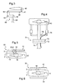
- the figure 1 presents a helicopter rotor 1.
- This rotor 1 is provided with a first and a second blade 10, 20 provided respectively with a first and a second fastening means 11, 21 to the hub 2 of the rotor 1.
- the fastening means 11, 21 are fixed to the hub 2 by usual means not shown, via laminated spherical abutments for example, allowing, among other things, each blade 10, 20 to pivot about its first longitudinal axis 13, 23.
- the blades 10, 20 are secured to their fastening means 11, 21 by pins 18. Nevertheless, the fastening means may be integral with the blades without departing from the scope of the invention.
- first and second lift elements 12, 22 are respectively mechanically connected to the first and second blades 10, 20 via first and second mechanical links 14, 24. More precisely, the first and second lift elements 12, 22 are respectively linked to the fixing means 11, 21 of the attachment zone 200 of the first and second blades 10, 20.
- Each mechanical connection 14, 24 is provided with an angle 15, 25 bent secured by its first end EX1, EX1 'to a blade 10, 20 and its second end EX2, EX2' to a hinge 16, 26 of the element lift 12, 22 associated with said blade 10, 20.
- this hinge 16, 26 the lift element is adapted to perform a rotary movement around its second longitudinal axis 17, 27 of pitch variation.
- a first end EX1 of the first angle 15 is then secured to the first fastening means 11, by screws not shown for example, while the second end EX2 of this first angle 15 is integral with the lift element 12 in rotation around the beat axis 302 of this lift element 12 being connected to a first articulation 16 of the first lift element 12.
- the first articulation 16 then allows the first lift element 12 to rotate about its second longitudinal axis 17 of step variation.
- a first end EX1 'of the second angle 25 is secured to the second fastening means 21 while the second end EX2' of this second angle 25 is integral with the lift element 22 in rotation about the beat axis of this lift element 22 being connected to a second hinge 26 of the second lift element 22.
- the second hinge 26 thus allows the second lift element 22 to rotate about its second longitudinal axis 27 of pitch variation.
- the first and second joints 16, 26 could thus be secured to the second ends EX2, EX2 'of the first and second angles 15, 25 as shown in FIG. figure 10 .
- the first hinge 16 of the first lift element 12 is then provided with a support means 300 and a fastener with three degrees of freedom 301, a spherical abutment for example.
- the support means 300 passes right through the first angle 15, passing through an orifice 303 formed in this second end EX2, before reaching the fastener with three degrees of freedom 301 secured to the hub 2.
- the three degree of freedom clip 301 is dimensioned to minimize the distance separating the beat axis 302 from the first lift member 12 to the first longitudinal pitch axis 13 of the corresponding first blade 10 so that said beat axis 302 and said first longitudinal axis 13 are substantially merged.
- a lift element is mechanically linked to a single blade.
- the pilot of the helicopter then adjusts the lift generated by the lift elements 12, 22 to make them beat.
- each lift element is integral in rotation with a first longitudinal axis 13, 23 of pitch variation of the blade 10, 20 to which it is connected.
- the first lift element 12 beats, it rotates about the first longitudinal axis 13 of the first blade 10.
- This lift element 12 being mechanically connected to the first attachment means 11 of the first blade 10, this first blade realizes at its rotational movement about the first longitudinal axis 13.
- the pitch of the first blade 10 is thus modified.
- the second lift member 22 beats, it starts a rotation around the first longitudinal axis 23 of the second blade 20 and drives with it the second blade 20 so as to change its pitch.
- the pilot controls the pitch of these lift elements, using conventional controls not shown in the figures, so as to rotate the lift element 12 , 22 concerned about its second longitudinal axis 17, 27 of variation of pitch.
- the rotor 1 comprises a main link 40 per lift element for controlling the pitch of this lift element.
- Each main link 40 is then articulated to an anchor point 41 offset from the lift element, more precisely a point remote from the support means 300 of the articulation 16.
- the anchor point 41 is said to be “offset” in the where it is not on the second longitudinal axis 17.
- the rotor 1 is equipped with a swashplate 50.
- This swashplate 50 has a non-rotating plate 52 connected to a non-rotating zone of the helicopter by a compass 53. If the non-rotating plate 52 is not rotated by the power plant of the helicopter, it can nevertheless be inclined relative to the mast 5 of the rotor 1, through a ball joint, via servo unrepresented and activated by the pilot.
- the swashplate 50 is provided with a turntable 51 integral in rotation with the mast 5. Note that the swashplate 50 is of a conventional type known to those skilled in the art.
- the main links 40 are according to this first embodiment articulated on the one hand on the anchor point 41 of the associated lift element, and on the other hand on the turntable 51 which drives them in rotation.
- anchor point 41 is, according to this first embodiment, deported using an offset 42 substantially orthogonal to the direction Z according to which the mast 5 is directed.
- the rotor 1 further comprises a return means 60, L-shaped, by lift element.
- Each return means 60 provided with a first and a second limb 61, 62 perpendicular to each other, is fixed on the hub 2 of the rotor 1 by a rod 63 at the junction of the first and second branches 61, 62 Each return means 60 is then free to perform a rotary movement around its rod 63.
- Each main link 40 is articulated on the anchoring point 41 of the associated lift element and on the first branch 61 of a return means 60.
- the main link 40 is thus substantially horizontal, in the helicopter coordinate system, and parallel to the second branch 62.
- the anchor point 41 is offset with an offset 42 substantially parallel to the direction Z in which the mast 5 is directed.
- the offset 42 is then substantially contained in a vertical plane containing the second longitudinal axis 17 of variation of pitch of the lift element 10.
- the rotor 1 comprises a secondary link 64 articulated on the one hand on the second branch 62 and on the other hand, the turntable 51.
- the secondary link is then substantially vertical, in the helicopter coordinate system, and parallel to the first branch 61.
- the turntable 51 tilts and echoes its movement to the secondary link 64.
- This secondary link 64 exerts a force on the second branch 62 of the deflection means 60 which rotates about its rod 63.
- main link 40 is then pushed or pulled as the case which allows to change the pitch of the lift element.
- the first branch 61 on which is articulated the main link 40 represents the branch of the return means 60 closest to the fuselage of the helicopter.
- the main link 40 is then fixed on the outer face F2 of the return means directed towards the lift element, while the secondary link 64 is fixed on the inner face F1 of this deflection means 60 facing the hub 2.
- the first branch 61 on which is articulated the main link 40 represents the branch of the deflection means 60 farthest from the fuselage of the helicopter.
- the figure 4 presents a third embodiment of the invention.
- Each main link 40 is secured to an actuator 70, possibly piezoelectric type, able to pull or push.
- Each actuator 70 is fixed for example to the mast 5 of the rotor by a flange provided for this purpose.
- the helicopter comprises an electrical collector 71, of a known type, provided with a non-rotating element 72 and a rotating element 73 equipped with brushes, or equivalent, allowing the circulation of an electric current.
- the rotating element 73 of the electrical collector 71 is then connected by an electric cable 75 to the actuator 70, the non-rotating element 72 being connected by an electric cable 74 to a power supply source of the helicopter, and possibly especially at the controls of the pilot.
- the pilot can order the retraction or extension of the actuator to vary the pitch of the associated lift element.
- the helicopter is advantageously equipped with a stop means 30 levator elements to limit their beat.
- This abutment means 30 comprises an upper plate 31 which partially or completely overlaps the hub 2 of the rotor 1.
- the upper plate 31 is therefore facing the upper part 3 of the hub 2 furthest from the fuselage of the helicopter.
- the stop means 30 is also provided with a stroke limiter 32, a jack for example, for each lift element.
- Each stroke limiter 32 is then fixed on the upper plate 31 and on the second end EX2, EX2 'of the bracket 15, 25 corresponding to the lift element 12 associated.
- the predetermined stroke of the stroke limiter thus advantageously limits the flapping of the lift element 12.
- the stop means 30 comprises not a race limiter but a lower plate 33 opposite the lower portion 4 of the hub 2 closest to the fuselage of the helicopter.
- the upper and lower plates 31, 33 protrude from the hub 2.
- the flap of the blade exceeds a certain threshold, the second end EX2, EX2 'of the bracket 15, 25 corresponding to the lift element comes into contact with the upper plate 31, or the lower plate 33, which stops its movement.
- Damping elements an elastomer abutment for example, can be arranged on the top 31 and lower 33 plates so that the joint is not damaged by the shock resulting from the contact.
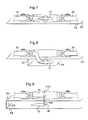
- the blades 10, 20 are all contained in a first plane P1 when they do not beat.
- the first plane P1 thus contains the first longitudinal axes 13, 23 of pitch variation of the blades 10, 20.
- the sustaining elements are all contained in a single plane P2.
- the second plane P2 contains the second longitudinal axes 17, 27 of variation of pitch of the lift elements 12, 22.
- the first and second planes P1 and P2 are merged.
- first and second planes P1, P2 are offset relative to each other, the first plane P1 being located slightly above the second plane P2.
- the shift E1 existing between the first and second planes P1, P2 is of the order of the thickness of the lift element.
- an intermediate link 100 is arranged between the second end EX2 of each bracket and the hinge 16 of the associated lift element 12.
- lift element 12 drawn on the Figures 8 and 9 is preferably supported by the hinge 16 of the lift element 12 being further fixed to the mast of the rotor for example.
- the figures describe a rotor having two blades and consequently two lift elements.
- the invention is adaptable to a helicopter with a larger number of blades without any difficulty.
- Figures 1 and 2 show that the bracket mechanically connecting a lift element to a corresponding blade is fixed by its first end to the fixing means of said blade.
- this first end of the angle can be secured not to the fastening means but to the blade itself, to a foot section of the blade for example, especially since the fastening means can be integrated in this blade.
- the angle is fixed to the attachment zone 200 of the blade to the rotor hub shown in FIG. figure 1 .
Landscapes
- Engineering & Computer Science (AREA)
- Mechanical Engineering (AREA)
- Aviation & Aerospace Engineering (AREA)
- Toys (AREA)
Description
La présente invention concerne un hélicoptère muni d'une pluralité d'éléments sustentateurs pour commander l'incidence aérodynamique de ses pales. Par suite, cette invention se situe dans le domaine technique restreint des commandes de pas de pales d'hélicoptère.The present invention relates to a helicopter having a plurality of lift elements for controlling the aerodynamic incidence of its blades. As a result, this invention is in the restricted technical field of helicopter blade pitch controls.
En effet, un hélicoptère comporte communément un rotor principal de sustentation et de propulsion pourvu d'une pluralité de pales.Indeed, a helicopter commonly comprises a main lift and propulsion rotor provided with a plurality of blades.
Les pales du rotor principal décrivent un cône très ouvert, dénommé « cône rotor » par l'homme du métier, dont le plan de rotation est perpendiculaire à la portance générale générée par ce rotor principal. Cette portance générale du rotor principal peut alors être décomposée en une force verticale de sustentation et une force horizontale qui assure la translation de l'hélicoptère.The blades of the main rotor describe a very open cone, called "rotor cone" by the skilled person, the plane of rotation is perpendicular to the general lift generated by the main rotor. This general lift of the main rotor can then be decomposed into a vertical lift force and a horizontal force which ensures the translation of the helicopter.
Par suite, le rotor principal assure bien la sustentation et la propulsion de l'hélicoptère.As a result, the main rotor ensures the lift and propulsion of the helicopter.
De plus, en contrôlant la forme et l'inclinaison du cône rotor par rapport au référentiel hélicoptère, un pilote peut diriger précisément l'hélicoptère.In addition, by controlling the shape and inclination of the rotor cone relative to the helicopter reference system, a pilot can precisely steer the helicopter.
Afin d'agir sur ce cône rotor, on tend à faire battre les pales de façon à modifier leur inclinaison par rapport au plan d'entraînement du rotor, ce plan d'entraînement étant perpendiculaire au mât du rotor.In order to act on this rotor cone, it tends to beat the blades so as to change their inclination relative to the drive plane of the rotor, the drive plane being perpendicular to the mast of the rotor.
Par suite, l'hélicoptère est pourvu de moyens spécifiques destinés à faire varier le pas de chaque pale, et par conséquent l'incidence aérodynamique de chaque pale par rapport au flux d'air incident traversé par la pale.As a result, the helicopter is provided with specific means for varying the pitch of each blade, and therefore the aerodynamic incidence of each blade relative to the incident air flow traversed by the blade.
En faisant varier le pas d'une pale, on modifie la portance qu'elle génère ce qui a pour conséquence le battement de la pale.By varying the pitch of a blade, the lift it generates is modified, which causes the blade to beat.
Afin de contrôler la portance générale du rotor, en intensité et en direction, le pilote de l'hélicoptère agit donc généralement sur la valeur de l'angle de pas de chaque pale en commandant une rotation de la pale autour de son axe longitudinal de pas.In order to control the overall lift of the rotor, in intensity and direction, the pilot of the helicopter therefore generally acts on the value of the pitch angle of each blade by controlling a rotation of the blade about its longitudinal axis of pitch .
Ainsi, lorsque le pilote ordonne une variation collective de pas, c'est à dire une variation identique du pas de toutes les pales, ce pilote fait varier l'intensité de la portance générale du rotor principale de manière à contrôler l'altitude et la vitesse de l'hélicoptère.Thus, when the pilot orders a collective pitch variation, that is to say an identical pitch variation of all the blades, this pilot varies the intensity of the general lift of the main rotor so as to control the altitude and speed of the helicopter.
A contrario, une variation de pas collectif est sans effet sur la direction de cette portance générale.On the other hand, a variation of the collective pitch has no effect on the direction of this general lift.
En effet, pour modifier la direction de la portance générale générée par le rotor, il convient d'incliner le cône rotor en réalisant une variation non pas collective mais cyclique de pas. Dans ce cas de figure, le pas d'une pale varie en fonction de son azimut et passe durant un tour complet d'une valeur maximale à une valeur minimale obtenues dans des azimuts opposés.Indeed, to change the direction of the general lift generated by the rotor, it is appropriate to tilt the rotor cone by realizing a variation not collective but cyclic step. In this case, the pitch of a blade varies according to its azimuth and passes during a complete revolution from a maximum value to a minimum value obtained in opposite azimuths.
La variation cyclique du pas des pales est à l'origine d'une variation cyclique de la portance des pales et donc de l'inclinaison du cône rotor. En commandant la variation cyclique du pas des pales, le pilote contrôle l'assiette de l'aéronef et sa translation.The cyclic variation of the pitch of the blades is at the origin of a cyclic variation of the lift of the blades and thus of the inclination of the rotor cone. By controlling the cyclic variation of the pitch of the blades, the pilot controls the attitude of the aircraft and its translation.
On connaît par le document
Selon ce document, un rotor d'hélicoptère est muni de deux pales solidaires chacune d'un manchon fixé à un moyeu.According to this document, a helicopter rotor is provided with two blades each secured to a sleeve fixed to a hub.
Le pilote commande le pas collectif des pales à l'aide d'un levier agissant sur une tige logée à l'intérieur du mât rotor. Cette tige répercute son mouvement sur une première et une deuxième bielles fixées au moyeu. En manoeuvrant le levier de commande de pas collectif, le pilote entraîne une translation de ladite tige ce qui génère une rotation du moyeu et donc des pales autour d'un axe de variation de pas.The pilot controls the collective pitch of the blades using a lever acting on a rod housed inside the rotor mast. This rod echoes its movement on a first and a second connecting rods fixed to the hub. By operating the control lever collective pitch, the driver causes a translation of said rod which generates a rotation of the hub and therefore the blades around a pitch variation axis.
Par ailleurs, le moyeu est solidarisé à un premier et un deuxième éléments sustentateurs agencés dans le plan des pales via un premier et deuxième arbres de liaison rigidement liés entre eux, l'axe longitudinal des éléments sustentateurs étant perpendiculaire aux axes longitudinaux des pales. Ces éléments sustentateurs sont dénommés « palette » par l'homme du métier.Furthermore, the hub is secured to a first and a second lift elements arranged in the plane of the blades via a first and second connecting shafts rigidly interconnected, the longitudinal axis of the lift elements being perpendicular to the longitudinal axes of the blades. These lift elements are called "pallet" by the skilled person.
Chaque arbre de liaison est en outre relié à un plateau de commande, dénommé plateau cyclique, via un compas. Plus précisément, le plateau cyclique comportant un plateau tournant et un plateau non tournant, les compas sont fixés sur le plateau tournant du plateau cyclique.Each link shaft is further connected to a control plate, called a swashplate, via a compass. More specifically, the swashplate having a turntable and a non-rotating plate, the compasses are fixed on the turntable of the swashplate.
En outre, le plateau non tournant comporte une barre dont le pilote peut se saisir.In addition, the non-rotating plate has a bar which the driver can seize.
Pour contrôler le pas cyclique des pales, le pilote manoeuvre la barre pour incliner le plateau non tournant, et par suite le plateau tournant. L'inclinaison du plateau tournant est alors répercutée sur les premier et deuxième arbres de liaison via les compas ce qui permet de modifier le pas des éléments sustentateurs.To control the cyclic pitch of the blades, the pilot maneuvers the bar to tilt the non-rotating plate, and consequently the turntable. The inclination of the turntable is then passed on the first and second linkage trees via the compass which allows to change the pitch of the lift elements.
La portance générée par ces éléments sustentateurs varie donc ce qui entraine un battement de ces derniers et par voie de conséquence un basculement du moyeu.The lift generated by these lift elements therefore varies which causes a beat of the latter and consequently a tilting of the hub.
Le moyeu s'inclinant, les deux pales verront leur propre pas modifié.As the hub tilts, both blades will see their own modified pitch.
Ce premier dispositif est relativement simple mais impose la présence d'un plateau cyclique pénalisant d'un point de vue masse et aérodynamisme.This first device is relatively simple but imposes the presence of a cyclic plateau penalizing from a mass and aerodynamic point of view.
De plus, il implique la présence de deux sous-ensembles pour respectivement commander la variation collective de pas et la variation cyclique du pas des pales ce qui induit des masses importantes et augmente les risques de panne.In addition, it involves the presence of two subassemblies to respectively control the collective pitch variation and the cyclic variation of the pitch of the blades which induces large masses and increases the risk of failure.
Enfin, les éléments sustentateurs sont censés faire varier cycliquement le pas des pales. Toutefois, ce n'est pas réellement le cas, du moins au sens strict, dans la mesure où les deux éléments sustentateurs agissent conjointement sur le moyeu et donc sur les deux pales de façon simultanée et identique.Finally, the lift elements are supposed to cyclically vary the pitch of the blades. However, this is not really the case, at least in the strict sense, insofar as the two lift elements act together on the hub and therefore on both blades simultaneously and identically.
En outre, on constate que les efforts à fournir par le pilote pour incliner les éléments sustentateurs, en agissant sur la barre du plateau non tournant sont parfois extrêmement importants.In addition, it can be seen that the efforts to be made by the pilot to tilt the lift elements, by acting on the bar of the non-rotating plate are sometimes extremely important.
Pour remédier à ce dernier inconvénient, on connaît un deuxième dispositif par le document
Désormais, les éléments sustentateurs sont chacun équipés d'un volet. Les compas agencés sur le plateau tournant n'entrainent pas la variation de pas des éléments sustentateurs mais l'inclinaison des volets par rapport à ces éléments sustenteurs.Now, the lift elements are each equipped with a shutter. The compasses arranged on the turntable do not cause the variation of pitch of the lift elements but the inclination of the flaps with respect to these lift elements.
En faisant varier l'inclinaison du volet, on modifie la portance de l'ensemble élément sustentateur/ volet et par suite le pas des pales.By varying the inclination of the flap, the lift of the lift / shutter and consequently the pitch of the blades is modified.
L'effort à exercer par le pilote pour faire varier le pas des pales est alors amoindri par rapport au premier dispositif dans la mesure où la surface portante du volet est faible comparée à la surface portante de l'élément sustentateur.The effort to be exerted by the pilot to vary the pitch of the blades is then reduced compared to the first device insofar as the bearing surface of the flap is small compared to the bearing surface of the lift element.
Néanmoins, les inconvénients mentionnés précédemment demeurent. De plus, ces premier et deuxième dispositifs ne sont pas à priori applicables sur un hélicoptère comportant plus deux pales dans la mesure où le moyeu ne peut tourner autour d'un unique axe durant la variation cyclique de pas.Nevertheless, the disadvantages mentioned above remain. In addition, these first and second devices are not a priori applicable on a helicopter having more than two blades in that the hub can rotate around a single axis during the cyclic pitch variation.
On connait, par le document
Les commandes de pas, collectif et cyclique, du pilote sont reliées à trois servocommandes, via des bielles et des combinateurs ou encore des commandes électriques, solidarisées au plateau non tournant d'un plateau cyclique.The pilot's collective and cyclic pitch controls are connected to three servocontrols, via connecting rods and combiners or electrical controls, secured to the non-rotating plate of a swashplate.
De plus, le plateau cyclique est lié mécaniquement à chaque pale par une bielle de commande de pas.In addition, the swashplate is mechanically linked to each blade by a pitch control rod.
Lorsque le pilote souhaite modifier le pas collectif des pales, il agit sur une commande qui ordonne aux trois servocommandes de faire monter ou descendre l'ensemble du plateau cyclique, à savoir ces plateaux non tournant et tournant.When the pilot wishes to change the collective pitch of the blades, he acts on a command that orders the three servocontrols to raise or lower the entire swashplate, namely these non-rotating and rotating plates.
Les bielles de commande de pas sont alors toutes déplacées de la même distance ce qui implique que le pas de toutes les pales varie du même angle.The pitch control rods are then all moved the same distance which implies that the pitch of all blades varies the same angle.
A contrario, pour faire varier le pas cyclique des pales afin de diriger l'hélicoptère dans une direction donnée, le pilote ordonne le déplacement d'une unique servocommande par exemple.Conversely, to vary the cyclic pitch of the blades to direct the helicopter in a given direction, the pilot orders the movement of a single servo control for example.
Le plateau cyclique ne se déplace par verticalement mais s'incline alors par rapport au mât du rotor. Chaque bielle de commande de pas se déplace selon une direction et une valeur qui lui est propre et il en va de même pour le pas de la pale associée.The swashplate moves vertically but then tilts relative to the rotor mast. Each pitch control rod moves in a direction and a value of its own and the same for the pitch of the associated blade.
La commande de pas est d'une certaine manière individualisée, contrairement au premier et deuxième dispositifs, puisque chaque pale est commandé par sa propre bielle de commande de pas.The pitch control is in some way individualized, unlike the first and second devices, since each blade is controlled by its own pitch control rod.
Ce troisième dispositif est très efficace ce qui explique sa généralisation. Néanmoins, les efforts à fournir pour manoeuvrer les pales étant importants, particulièrement sur les hélicoptères de fort tonnage, les servocommandes et le plateau cyclique ont des masses et des dimensions importantes ce qui est très pénalisant.This third device is very effective which explains its generalization. Nevertheless, the efforts to be made to maneuver the blades being important, particularly on large helicopters, the servocontrols and the swashplate have masses and large dimensions which is very penalizing.
De plus, leur présence tend à créer des perturbations aérodynamiques.In addition, their presence tends to create aerodynamic disturbances.
La présente invention a pour alors objet de proposer un hélicoptère permettant de s'affranchir des limitations mentionnées ci-dessus.The present invention is then intended to provide a helicopter to overcome the limitations mentioned above.
Ainsi, l'invention vise à obtenir un dispositif et un procédé de changement de pas des pales du rotor principal d'un l'hélicoptère qui soit à la fois léger et efficace en autorisant un parfait contrôle des pas collectif et cyclique des pales, quel que soit le nombre de pales du rotor.Thus, the object of the invention is to obtain a device and method for changing the pitch of the main rotor blades of a helicopter which is both light and efficient by allowing perfect control of the collective and cyclic pitch of the blades. regardless of the number of rotor blades.
Selon l'invention, un hélicoptère est muni d'un rotor principal comportant au moins deux pales, chaque pale étant pourvue d'un moyen de fixation à un moyeu du rotor. On note que le moyen de fixation de la pale au moyeu peut consister en un manchon solidarisé par des moyens usuels ou encore en un manchon faisant partie intégrante de la pale par exemple.According to the invention, a helicopter is provided with a main rotor comprising at least two blades, each blade being provided with a means of attachment to a hub of the rotor. Note that the means for fixing the blade to the hub may consist of a sleeve secured by conventional means or a sleeve integral with the blade for example.
Cet hélicoptère est remarquable en ce qu'il est muni d'un élément sustentateur par pale, chaque élément sustentateur étant lié mécaniquement à une unique pale pour faire varier le pas de ladite unique pale à laquelle l'élément sustentateur est lié.This helicopter is remarkable in that it is provided with a blade lift element, each lifting element being mechanically connected to a single blade to vary the pitch of said single blade to which the lift element is connected.
Le pas de chaque pale est donc commandé par un élément sustentateur lié à l'ancrage de la pale. Contrairement aux premier et deuxième dispositifs de l'art antérieur, chaque pale est donc bien commandée par son propre élément sustentateur.The pitch of each blade is controlled by a lift element linked to the anchoring of the blade. Unlike the first and second devices of the prior art, each blade is well controlled by its own lift element.
Chaque élément sustentateur est alors géré de manière indépendante, fonctionnellement et mécaniquement, de manière à faire varier individuellement le pas d'une unique pale.Each lift element is then managed independently, functionally and mechanically, so as to individually vary the pitch of a single blade.
De plus, le système est opérationnel indépendamment du nombre de pales dans la mesure où les éléments sustentateurs ne doivent pas obligatoirement présenter une angulation de 90° avec les pales ou se situer dans le même plan que les pales. L'invention est applicable sur un hélicoptère comportant au moins deux pales et non pas uniquement deux pales ce qui constitue un avantage certain.In addition, the system is operational regardless of the number of blades in that the lift elements do not necessarily have a 90 ° angulation with the blades or be in the same plane as the blades. The invention is applicable to a helicopter having at least two blades and not only two blades which is a definite advantage.
Par rapport au troisième dispositif de l'art antérieur, il est plus aisé de mouvoir un élément sustentateur de faibles dimensions plutôt qu'une pale relativement grande. De plus, l'effet aérodynamique généré par l'élément sustentateur permet de limiter les efforts à exercer.Compared to the third device of the prior art, it is easier to move a lift element of small dimensions rather than a relatively large blade. In addition, the aerodynamic effect generated by the lift element limits the efforts to be exerted.
Par ailleurs, l'invention peut comporter une ou plusieurs des caractéristiques additionnelles suivantes.Furthermore, the invention may include one or more of the following additional features.
Chaque élément sustentateur étant lié mécaniquement à une pale, chaque élément sustentateur est avantageusement solidaire en rotation de la pale à laquelle il est mécaniquement lié autour d'un premier axe longitudinal de variation de pas de la pale.Each lift element being mechanically connected to a blade, each lift element is advantageously rotationally integral with the blade to which it is mechanically linked around a first longitudinal axis of pitch variation of the blade.
En faisant battre un élément sustentateur, on génère une rotation de cet élément sustentateur, et par suite une rotation de la pale autour de son premier axe longitudinal.By causing a lifting element to beat, a rotation of this lifting element is generated, and consequently a rotation of the blade around its first longitudinal axis.
L'élément sustentateur commande donc de manière directe le pas de la pale, et non pas via le moyeu du rotor par exemple.The lift element thus directly controls the pitch of the blade, and not via the hub of the rotor, for example.
Pour faire varier le pas collectif, on agit sur l'ensemble des éléments sustentateurs pour que ces éléments sustentateurs battent de manière identique, alors que pour faire varier le pas cycliquement, on individualise les actions.To vary the collective pitch, we act on all the levator elements so that these levator elements beat identically, while to vary the pace cyclically individual actions.
Par conséquent, il est avantageux que chaque élément sustentateur soit lié mécaniquement à une unique pale par une liaison mécanique indépendante du moyeu du rotor, la liaison mécanique liant avantageusement l'élément sustentateur à une zone d'attache de la pale au moyeu, c'est à dire soit au moyen de fixation de la pale ou soit à un tronçon de la pale elle-même.Therefore, it is advantageous that each lift element is mechanically connected to a single blade by a mechanical connection independent of the hub of the rotor, the mechanical connection advantageously linking the lift element to a zone of attachment of the blade to the hub, that is to say either by means of attachment of the blade or to a section of the blade itself.
Ainsi, la liaison mécanique n'englobe pas le moyeu du rotor, contrairement aux premier et deuxième dispositifs de l'art antérieur pour lesquels chaque élément sustentateur est mécaniquement lié au moyeu et entraine le basculement de ce moyeu.Thus, the mechanical connection does not encompass the hub of the rotor, unlike the first and second devices of the prior art for which each lift element is mechanically connected to the hub and causes the tilting of the hub.
Plus précisément, chaque élément sustentateur étant lié mécaniquement à une unique pale par une liaison mécanique, cette liaison mécanique comporte éventuellement une cornière dont une première extrémité est solidarisée à la zone d'attache de la pale, plus précisément au moyen de fixation de la pale au moyeu ou à un tronçon de la pale elle même.More specifically, each lift element being mechanically connected to a single blade by a mechanical connection, this mechanical connection optionally comprises an angle of which a first end is secured to the blade attachment zone, more precisely by means of fixing the blade. to the hub or a section of the blade itself.
Selon une première et une deuxième variantes de l'agencement des éléments sustentateurs, chaque élément sustentateur est solidarisé en rotation autour de l'axe de battement dudit élément sustentateur à une deuxième extrémité de la cornière correspondante via une articulation permettant à l'élément sustentateur d'effectuer un mouvement rotatif autour d'un deuxième axe longitudinal de variation de pas de l'élément sustentateur.According to a first and a second variant of the arrangement of the lift elements, each lift element is secured in rotation around the axis of flapping of said lift element at a second end of the corresponding angle via a hinge allowing the lifting element to lift. rotating about a second longitudinal axis of pitch variation of the lift element.
Selon une troisième variante de l'agencement des éléments sustentateurs, une deuxième extrémité de chaque cornière est fixée par une biellette intermédiaire à l'élément sustentateur correspondant, plus précisément à l' articulation permettant à l'élément sustentateur d'effectuer un mouvement rotatif autour d'un deuxième axe longitudinal de variation de pas de l'élément sustentateur.According to a third variant of the arrangement of the lift elements, a second end of each bracket is fixed by an intermediate link to the corresponding lift element, specifically to the hinge allowing the lift element to perform a rotary movement around a second longitudinal axis of pitch variation of the lift element.
Selon les première et deuxième variantes, il est alors possible de fixer l'articulation de l'élément sustentateur à la deuxième extrémité de la cornière associée. De même, selon la troisième variante, on fixe l'articulation de l'élément sustentateur à la biellette intermédiaire.According to the first and second variants, it is then possible to fix the articulation of the lift element at the second end of the associated angle. Similarly, according to the third variant, the articulation of the lift element is fixed to the intermediate link.
Cependant, quelle que soit la variante de l'invention, il est avantageux de soutenir chaque élément sustentateur. L'articulation de chaque élément sustentateur est alors pourvue d'un moyen de soutien et d'une attache à trois degrés de liberté, le moyen de soutien étant solidarisé à l'élément sustentateur correspondant, l'attache à trois degrés de liberté étant fixée à une unité tournante comportant le mât du rotor et son moyeu ainsi que le moyen de fixation de la pale au moyeu du rotor.However, whatever the variant of the invention, it is advantageous to support each lift element. The articulation of each lift element is then provided with a support means and a fastener with three degrees of freedom, the support means being secured to the corresponding lift element, the attachment with three degrees of freedom being fixed a rotating unit comprising the mast of the rotor and its hub and the means for attaching the blade to the hub of the rotor.
Le moyen de soutien traverse alors la deuxième extrémité de la cornière de manière à permettre à l'élément sustentateur d'effectuer un mouvement rotatif autour de son deuxième axe longitudinal de variation de pas et d'entraîner en rotation la cornière autour de son axe de battement.The support means then passes through the second end of the angle so as to allow the lifting element rotating about its second longitudinal pitch axis and rotating the angle about its beat axis.
De plus, on note que l'attache à trois degrés de liberté, une butée sphérique par exemple, est dimensionnée pour minimiser la distance séparant l'axe de battement de l'élément sustentateur au premier axe longitudinal de variation de pas de la pale correspondante afin que ledit axe de battement et ledit premier axe longitudinal soient sensiblement confondus.In addition, it is noted that the three-degree of freedom fastener, a spherical abutment for example, is sized to minimize the distance separating the beat axis of the lift element from the first longitudinal axis of pitch variation of the corresponding blade. so that said beat axis and said first longitudinal axis are substantially merged.
Selon la première variante et éventuellement selon la deuxième variante, l'attache à trois degrés de liberté sera donc fixée au moyeu du rotor alors que selon la troisième variante elle sera fixée au mât du rotor, ou à un organe prolongeant ledit mât.According to the first variant and possibly according to the second variant, the fastener with three degrees of freedom will therefore be fixed to the hub of the rotor while according to the third variant it will be fixed to the mast of the rotor, or to a member extending said mast.
Indépendamment de l'agencement des éléments sustentateurs, selon le procédé mis en oeuvre par l'invention, décrit par la suite, le pilote de l'hélicoptère va commencer par modifier le pas de l'élément sustentateur pour modifier la portance générée par cet élément sustentateur. Cette modification entraîne un battement de l'élément sustentateur qui monte ou descend selon le cas de manière à entrainer en rotation la pale à laquelle il est lié mécaniquement autour de son premier axe longitudinal.Independently of the arrangement of the lift elements, according to the method implemented by the invention, described below, the pilot of the helicopter will begin by modifying the pitch of the lift element to modify the lift generated by this element. sustainer. This modification causes the lifting element to bounce up or down as the case may be so as to rotate the blade to which it is mechanically linked around its first longitudinal axis.
On comprend que les efforts à appliquer pour mettre en rotation un élément sustentateur de faible dimension autour de son deuxième axe longitudinal sont nettement inférieurs aux efforts nécessaires pour mettre en rotation une pale autour de son premier axe longitudinal de variation de pas, en appliquant les techniques mises en oeuvre par le troisième dispositif de l'art antérieur par exemple.It will be understood that the forces to be applied for rotating a low-lift element around its second longitudinal axis are much smaller than the forces required to rotate a blade about its first longitudinal axis of variation of pitch, by applying the techniques implemented by the third device of the prior art for example.
Par conséquent, il devient possible de simplifier le système de changement de pas des pales. Malgré le surpoids provenant des éléments sustentateurs et de leur liaison mécanique, l'invention reste étonnamment avantageuse par rapport au troisième dispositif connu.Therefore, it becomes possible to simplify the pitch change system of the blades. Despite the overweight coming from the lift elements and their mechanical connection, the invention remains surprisingly advantageous compared to the third known device.
Selon une première variante de l'agencement des éléments sustentateurs, les pales étant contenues dans un premier plan lorsqu'elles ne battent pas, les éléments sustentateurs liés mécaniquement auxdites pales étant contenus dans un deuxième plan lorsqu'ils ne battent pas, les premier et deuxième plans sont confondus. Les premier et deuxième axes de variation de pas sont donc disposés dans un même plan.According to a first variant of the arrangement of the lift elements, the blades being contained in a first plane when they do not beat, the lift elements mechanically linked to said blades being contained in a second plane when they do not beat, the first and second shots are confused. The first and second pitch variation axes are therefore arranged in the same plane.
En revanche, selon une deuxième et une troisième variantes de l'agencement des éléments sustentateurs, les premier et deuxième plans sont parallèles entre eux, un plan se trouvant au dessus de l'autre.On the other hand, according to a second and a third variant of the arrangement of the lift elements, the first and second planes are parallel to one another, one plane lying on top of the other.
La première variante est intéressante par sa simplicité. Néanmoins, les deuxième et troisième variantes sont optimisées en fonction du besoin.The first variant is interesting because of its simplicity. Nevertheless, the second and third variants are optimized according to the need.
La deuxième variante consiste à décaler faiblement, de l'ordre de grandeur de l'épaisseur de l'élément sustentateur, les premier et deuxième plans, en inclinant la cornière liant l'élément sustentateur à la zone d'attache de la pale correspondante, dans le but d'annuler les effets de la pesanteur sur les éléments sustentateurs.The second variant consists in slightly shifting, by the order of magnitude of the thickness of the lift element, the first and second planes, by inclining the angle connecting the lift element to the attachment zone of the corresponding blade, in order to cancel the effects of gravity on the lift elements.
En effet, le poids des éléments sustentateurs tend à les faire battre dans la direction de la pesanteur. Ce battement est à même d'entraîner une rotation des pales qui n'aurait pas été requise par le pilote.Indeed, the weight of the lift elements tends to make them beat in the direction of gravity. This beat is able to cause a rotation of the blades that would not have been required by the pilot.
Or, de manière surprenante, lorsque le deuxième plan est légèrement situé sous le premier plan, on constate que les efforts centrifuges, exercés sur les éléments sustentateurs lorsque le rotor tourne, redressent ces éléments sustentateurs de manière à contrecarrer l'influence néfaste de leur poids.Surprisingly, when the second plane is slightly under the foreground, it is found that the centrifugal forces exerted on the lift elements when the rotor rotates, straighten these lift elements so as to counteract the harmful influence of their weight. .
La troisième variante consiste à décaler sensiblement, de l'ordre de grandeur de la corde des éléments sustentateurs, les premier et deuxième plans à l'aide de la biellette intermédiaire pour étendre l'application de l'invention à un rotor possédant n'importe quel nombre de pales.The third variant consists in substantially shifting, by the order of magnitude of the rope of the lift elements, the first and second planes using the intermediate link to extend the application of the invention to a rotor having any what number of blades.
De plus, cette troisième variante permet d'optimiser les caractéristiques aérodynamiques du rotor en éloignant les éléments sustentateurs de la zone perturbée de la tête rotor.In addition, this third variant makes it possible to optimize the aerodynamic characteristics of the rotor by moving the lift elements away from the disturbed zone of the rotor head.
Par ailleurs, le rotor peut comporter de manière optionnelle un moyen de butée pour limiter le battement de chaque élément sustentateur.Furthermore, the rotor may optionally include a stop means for limiting the beat of each lift element.
Cette caractéristique garantit une certaine sécurité au système en empêchant que le battement des éléments sustentateurs soit trop important et par conséquent en limitant le pas des pales.This feature ensures a certain security to the system by preventing the beat of the lift elements is too important and therefore limiting the pitch of the blades.
Ce moyen de butée est pourvu d'une plaque supérieure qui recouvre au moins partiellement une partie supérieure du moyeu du rotor, cette partie supérieure étant située du côté du moyeu opposé au fuselage de l'hélicoptère.This abutment means is provided with an upper plate which at least partially covers an upper part of the hub of the rotor, this upper part being located on the side of the hub opposite the fuselage of the helicopter.
Selon une première version du moyen de butée, chaque élément sustentateur étant lié mécaniquement à une pale via successivement une articulation et une liaison mécanique, le moyen de butée comporte un limiteur de course par élément sustentateur. Chaque limiteur de course, un vérin par exemple, est alors agencé entre la plaque supérieure et chaque articulation pour limiter le battement de chaque élément sustentateur.According to a first version of the stop means, each lifting element being mechanically connected to a blade via successively a joint and a mechanical connection, the stop means comprises a limit limiter per lift element. Each stroke limiter, a jack for example, is then arranged between the upper plate and each articulation to limit the beat of each lift element.
Le battement de chaque élément sustentateur est alors limité par la course du limiteur de course associé.The beat of each lift element is then limited by the stroke of the associated stroke limiter.
Selon une deuxième version du moyen de butée, ce moyen de butée est pourvu d'une plaque inférieure qui recouvre au moins partiellement une partie inférieure du moyeu du rotor, la partie inférieure étant située du côté du moyeu en regard du fuselage de l'hélicoptère.According to a second version of the abutment means, this abutment means is provided with a lower plate which at least partially covers a lower part of the hub of the rotor, the lower part being located on the side of the hub facing the fuselage of the helicopter .
Le battement de l'élément sustentateur, ou son articulation à la liaison mécanique le liant à une pale, est alors limité par les plaques inférieure ou supérieure. En cas de battement trop important, l'élément sustentateur ou son articulation rentre en contact avec la plaque supérieure ou inférieure ce qui stoppe son déplacement.The beat of the lift element, or its articulation to the mechanical linkage linking it to a blade, is then limited by the lower or upper plates. In case of excessive beat, the lift element or its articulation comes into contact with the upper or lower plate which stops its movement.
Eventuellement, les plaques supérieure et inférieure peuvent être munies localement de moyens amortissant pour éviter de dégrader l'élément sustentateur ou son articulation lorsque ces derniers sont en butée.Optionally, the upper and lower plates may be locally provided with damping means to avoid degrading the lift element or its articulation when the latter are in abutment.
Quel que soit le mode de réalisation, l'hélicoptère comporte une biellette principale par élément sustentateur pour que le pilote puisse ajuster le pas de chaque élément sustentateur. Chaque biellette principale est alors articulée sur un point d'ancrage déporté d'un unique élément sustentateur pour commander le pas de l'élément sustentateur sur lequel la biellette principale est articulée.Whatever the embodiment, the helicopter has a main link per lift element so that the pilot can adjust the pitch of each lift element. Each main link is then articulated on a remote anchor point of a single lift element to control the pitch of the lift element on which the main link is articulated.
On comprend que le point d'ancrage est déporté par rapport au deuxième axe longitudinal de variation de pas de l'élément sustentateur pour commander la mise en rotation de cet élément sustentateur.It is understood that the anchor point is offset with respect to the second longitudinal axis of pitch variation of the element levitateur to control the rotation of this levator element.
Selon un premier mode de réalisation, le rotor principal comportant un plateau cyclique de commande de pas muni d'un plateau tournant et d'un plateau non tournant, chaque biellette principale est articulée sur le plateau tournant, et bien évidemment sur le point d'ancrage déporté de l'élément sustentateur.According to a first embodiment, the main rotor comprising a cyclic pitch control plate provided with a turntable and a non-rotating plate, each main link is articulated on the turntable, and of course on the point of remote anchoring of the lift element.
Le pilote commande le plateau cyclique, via des servocommandes par exemple, pour faire varier le pas des éléments sustentateurs et par suite des pales.The pilot controls the swashplate, via servocontrols, for example, to vary the pitch of the lift elements and consequently the blades.
A pale équivalente, les servocommandes de l'invention auront des dimensions et un poids réduits, par rapport aux servocommandes mises en oeuvre par le troisième dispositif connu.Equally equivalent, the servocontrols of the invention will have reduced dimensions and weight, compared to the servocontrols implemented by the third known device.
Selon un deuxième mode de réalisation, le rotor principal comportant un plateau cyclique de commande de pas muni d'un plateau tournant et d'un plateau non tournant, ladite biellette principale est articulée sur une première branche d'un moyen de renvoi d'angle, en forme de L par exemple, solidarisé au moyeu du rotor. Une deuxième branche du moyen de renvoi est alors reliée au plateau tournant par une bielle secondaire, cette bielle secondaire étant de fait articulée sur le plateau tournant.According to a second embodiment, the main rotor comprising a cyclic pitch control plate provided with a turntable and a non-rotating plate, said main link is articulated on a first branch of a deflection means , L-shaped for example, secured to the hub of the rotor. A second branch of the return means is then connected to the turntable by a secondary link, this secondary link being de facto articulated on the turntable.
Il est à noter que la biellette principale est articulée soit sur la branche du moyen de renvoi la plus proche du fuselage de l'hélicoptère, soit sur la branche du moyen de renvoi la plus éloignée du fuselage.It should be noted that the main link is articulated either on the branch of the return means closest to the fuselage of the helicopter, or on the branch of the return means furthest from the fuselage.
Contrairement au premier mode de réalisation, le plateau tournant n'est pas relié directement à la biellette principale de chaque élément sustentateur.Unlike the first embodiment, the turntable is not connected directly to the main link of each lift element.
En mettant en oeuvre le premier mode de réalisation, on constate que lorsque l'élément sustentateur bat vers le haut, son pas tend à décroitre si le point d'ancrage de l'élément sustentateur est agencé près du bord d'attaque de l'élément sustentateur.By implementing the first embodiment, it can be seen that when the lift element is beating upwards, its pitch tends to decrease if the anchoring point of the lift element is arranged near the leading edge of the lift element. lifting element.
A contrario, son pas va augmenter si le point d'ancrage de l'élément sustentateur est agencé près du bord de fuite de l'élément sustentateur, à savoir entre ledit bord de fuite et le deuxième axe longitudinal de variation de pas de l'élément sustentateur.Conversely, its pitch will increase if the anchoring point of the lift element is arranged near the trailing edge of the lift element, namely between said trailing edge and the second longitudinal axis of pitch variation of the lifting element.
Ce couplage entre le pas et le battement de l'élément sustentateur a un effet stabilisant sur la réponse de l'élément sustentateur mais il réduit l'efficacité du système puisqu'il limite la réponse à un ordre de pilotage.This coupling between the pitch and the beat of the lift element has a stabilizing effect on the response of the lift element but it reduces the effectiveness of the system since it limits the response to a control order.
En variante du premier mode de réalisation, le point d'ancrage de la biellette principale sur l'élément sustentateur peut être déporté à l'arrière de ce dernier, près de son bord de fuite donc, pour obtenir un couplage pas/battement tendant à augmenter le battement lorsque le pas augmente. Un tel couplage tend à accroître l'efficacité du dispositif mais ce dernier risque de devenir instable si le couplage est excessif.As a variant of the first embodiment, the anchor point of the main link on the lift element can be offset at the rear of the latter, near its trailing edge, so to obtain a pitch / beat coupling tending to increase the beat when the step increases. Such coupling tends to increase the effectiveness of the device but the latter may become unstable if the coupling is excessive.
De manière inattendue, en mettant en oeuvre le deuxième mode de réalisation, le pas de l'élément sustentateur reste constant en cas de battement. En d'autres termes, ce deuxième mode de réalisation permet de supprimer le couplage pas /battement de l'élément sustentateur.Unexpectedly, by implementing the second embodiment, the pitch of the lift element remains constant in case of a beat. In other words, this second embodiment makes it possible to eliminate the pitch / beat coupling of the lift element.
Ainsi, en utilisant soit le premier soit le deuxième mode de réalisation, il est possible d'introduire dans le dispositif n'importe quelle valeur de couplage pas/battement, et d'obtenir de la sorte la meilleure efficacité sans instabilité.Thus, using either the first or the second embodiment, it is possible to introduce into the device any step / beat coupling value, and thus obtain the best efficiency without instability.
Selon un troisième mode de réalisation, l'hélicoptère comporte un actionneur, de type piézoélectrique par exemple, par biellette principale. Chaque biellette principale est alors commandée par un actionneur fixé au moyeu ou au mât du rotor.According to a third embodiment, the helicopter comprises an actuator, of piezoelectric type for example, by main link. Each main link is then controlled by an actuator attached to the hub or to the rotor mast.
Cet actionneur peut être alimenté électriquement via un collecteur électrique agencé sur un mât tournant du rotor. L'énergie électrique étant acheminée au moyen de câbles électriques depuis un générateur installé dans le fuselage de l'hélicoptère, le collecteur a pour fonction de transférer l'énergie depuis le repère fixe du fuselage vers le repère tournant du rotor.This actuator can be electrically powered via an electrical collector arranged on a rotating mast of the rotor. Electrical energy being conveyed by means of electric cables from a generator installed in the fuselage of the helicopter, the function of the collector is to transfer energy from the fixed reference of the fuselage towards the rotating mark of the rotor.
Toutefois, il est avantageux de réaliser un générateur électrique à l'aide du mât tournant du rotor.However, it is advantageous to make an electric generator using the rotating mast of the rotor.
De façon usuelle, on dispose le stator du générateur électrique à l'intérieur du mât du rotor, le stator étant de plus rigidement lié au fond de la boite de transmission principale. L'organe tournant du générateur est alors rigidement lié au mât rotor.In the usual way, the stator of the electric generator is placed inside the mast of the rotor, the stator being moreover rigidly connected to the bottom of the main gearbox. The rotating member of the generator is then rigidly connected to the rotor mast.
Ainsi, la rotation du mât rotor permet au générateur de générer l'électricité nécessaire au bon fonctionnement des actionneurs des éléments sustentateurs.Thus, the rotation of the rotor mast allows the generator to generate the electricity necessary for the proper functioning of the actuators of the lift elements.
Les commandes de vol du pilote envoient un signal électrique à un actionneur qui pousse ou tire une biellette principale pour faire varier le pas de l'élément sustentateur associé. Ces commandes peuvent être transmises par un moyen de transmission sans fil par ondes électromagnétiques dans les gammes radioélectriques, infrarouges, ou encore par hyperfréquences.Pilot flight controls send an electrical signal to an actuator that pushes or pulls a main link to vary the pitch of the associated lift element. These commands can be transmitted by a means of wireless transmission by electromagnetic waves in the radio range, infrared, or by microwave.
Ce troisième mode de réalisation ne nécessite donc pas l'implémentation d'un plateau cyclique.This third embodiment therefore does not require the implementation of a swashplate.
La présente invention a aussi pour objet le procédé mis en oeuvre par l'hélicoptère revendiqué.The present invention also relates to the method implemented by the claimed helicopter.
Selon l'invention, un procédé pour faire varier le pas d'une pale d'un rotor d'hélicoptère comportant au moins deux pales est remarquable en ce que, un élément sustentateur étant uniquement lié à ladite pale, on ajuste la portance générée par l'élément sustentateur afin que cet élément sustentateur batte pour entraîner en rotation la pale à laquelle il est lié autour d'un premier axe longitudinal de variation de pas de cette pale.According to the invention, a method for varying the pitch of a blade of a helicopter rotor comprising at least two blades is remarkable in that, since a lifting element is solely connected to said blade, the lift generated by the lift element so that the lift element beats to rotate the blade to which it is linked around a first longitudinal axis of pitch variation of this blade.
On remarquera que selon les premier et deuxième dispositifs de l'art antérieur utilisant deux éléments sustentateurs, les deux éléments sustentateurs agissent conjointement sur le moyeu du rotor qui entraine en rotation les deux pales. A contrario, selon le procédé de l'invention, on modifie la portance d'un élément sustentateur qui agit directement sur une unique pale.It will be noted that according to the first and second devices of the prior art using two lift elements, the two lift elements act together on the hub of the rotor which rotates the two blades. In contrast, according to the method of the invention, the lift of a lift element is modified which acts directly on a single blade.
Ainsi, on ajuste la portance de l'élément sustentateur en modifiant le pas de cet élément sustentateur et donc en faisant tourner l'élément sustentateur autour d'un deuxième axe longitudinal de variation de pas de l'élément sustentateur.Thus, the lift of the lift element is adjusted by modifying the pitch of this lift element and thus by rotating the lift element around a second longitudinal axis of variation of pitch of the lift element.
L'invention et ses avantages apparaîtront avec plus de détails dans le cadre de la description qui suit avec des exemples de réalisation donnés à titre illustratif en référence aux figures annexées qui représentent :
- la
figure 1 , une vue isométrique d'un premier mode de réalisation de l'invention ayant des éléments sustentateurs soutenus par le moyeu, - la
figure 2 , une vue de côté d'une première forme du deuxième mode de réalisation de l'invention, - la
figure 3 , une vue de côté d'une deuxième forme du deuxième mode de réalisation de l'invention, - la
figure 4 , une vue de côté schématique d'un troisième mode de réalisation, - la
figure 5 , une vue de côté d'une première version du moyen de butée, - la
figure 6 , une vue de côté d'une deuxième version du moyen de butée, - la
figure 7 , une vue de côté d'une première variante de l'agencement des éléments sustentateurs, - la
figure 8 , une vue de côté d'une deuxième variante de l'agencement des éléments sustentateurs, - la
figure 9 , une vue de côté d'une troisième variante de l'agencement des éléments sustentateurs, et - la
figure 10 , une vue isométrique d'un premier mode de réalisation de l'invention n'ayant pas des éléments sustentateurs soutenus par le moyeu.
- the
figure 1 an isometric view of a first embodiment of the invention having lift elements supported by the hub, - the
figure 2 , a side view of a first form of the second embodiment of the invention, - the
figure 3 a side view of a second form of the second embodiment of the invention, - the
figure 4 a schematic side view of a third embodiment, - the
figure 5 , a side view of a first version of the stop means, - the
figure 6 , a side view of a second version of the stop means, - the
figure 7 a side view of a first variant of the arrangement of the lift elements, - the
figure 8 , a side view of a second variant of the arrangement of the lift elements, - the
figure 9 , a side view of a third variant of the arrangement of the lift elements, and - the
figure 10 , an isometric view of a first embodiment of the invention having no lift elements supported by the hub.
Les éléments présents dans plusieurs figures distinctes sont affectés d'une seule et même référence.The elements present in several separate figures are assigned a single reference.
La
Sur les figures, les pales 10, 20 sont solidarisées à leur moyen de fixation 11, 21 par des broches 18. Néanmoins, les moyens de fixation peuvent faire partie intégrante des pales sans sortir du cadre de l'invention.In the figures, the
De plus, le rotor 1 comporte un élément sustentateur 12, 22 par pale, chaque élément sustentateur étant situé en amont de la pale associée par rapport au sens d'avancement S de ladite pale associée. Ainsi, un premier et un deuxième éléments sustentateurs 12 ,22 sont respectivement liés mécaniquement aux première et deuxième pales 10, 20 via une première et une deuxième liaisons mécaniques 14, 24. Plus précisément, les premier et deuxième éléments sustentateurs 12 ,22 sont respectivement liés aux moyens de fixation 11, 21 de la zone d'attache 200 des première et deuxième pales 10, 20.In addition, the
Chaque liaison mécanique 14, 24 est pourvue d'une cornière 15, 25 coudée solidarisée par sa première extrémité EX1, EX1' à une pale 10, 20 et par sa deuxième extrémité EX2, EX2' à une articulation 16, 26 de l'élément sustentateur 12, 22 associé à ladite pale 10, 20. Grâce à cette articulation 16, 26, l'élément sustentateur est apte à réaliser un mouvement rotatif autour de son deuxième axe longitudinal 17, 27 de variation de pas.Each
Ainsi, une première extrémité EX1 de la première cornière 15 est alors solidarisée au premier moyen de fixation 11, par des vis non représentées par exemple, alors que la deuxième extrémité EX2 de cette première cornière 15 est solidaire de l'élément sustentateur 12 en rotation autour de l'axe de battement 302 de cet élément sustentateur 12 en étant reliée à une première articulation 16 du premier élément sustentateur 12. La première articulation 16 autorise alors le premier élément sustentateur 12 à effectuer une rotation autour de son deuxième axe longitudinal 17 de variation de pas.Thus, a first end EX1 of the
De même, une première extrémité EX1' de la deuxième cornière 25 est solidarisée au deuxième moyen de fixation 21 alors que la deuxième extrémité EX2' de cette deuxième cornière 25 est solidaire de l'élément sustentateur 22 en rotation autour de l'axe de battement de cet élément sustentateur 22 en étant reliée à une deuxième articulation 26 du deuxième élément sustentateur 22. La deuxième articulation 26 autorise donc le deuxième élément sustentateur 22 à effectuer une rotation autour de son deuxième axe longitudinal 27 de variation de pas.Similarly, a first end EX1 'of the
Les première et deuxième articulations 16, 26 pourraient ainsi être solidarisées aux deuxièmes extrémités EX2, EX2' des première et deuxième cornières 15, 25 comme le montre la
Néanmoins, en référence à la
La première articulation 16 du premier élément sustentateur 12 est alors pourvue d'un moyen de soutien 300 et d'une attache à trois degrés de liberté 301, une butée sphérique par exemple. Le moyen de soutien 300 traverse de part en part la première cornière 15, en passant par un orifice 303 ménagé dans cette deuxième extrémité EX2, avant d'atteindre l'attache à trois degrés de liberté 301 solidarisée au moyeu 2.The
L'attache à trois degrés de liberté 301 est dimensionnée pour minimiser la distance séparant l'axe de battement 302 du premier élément sustentateur 12 au premier axe longitudinal 13 de variation de pas de la première pale 10 correspondante afin que ledit axe de battement 302 et ledit premier axe longitudinal 13 soient sensiblement confondus.The three degree of
On comprend que tous les éléments sustentateurs sont avantageusement munis d'une telle articulation.It is understood that all the lift elements are advantageously provided with such a hinge.
Par conséquent, un élément sustentateur est lié mécaniquement à une unique pale.Therefore, a lift element is mechanically linked to a single blade.
Le pilote de l'hélicoptère ajuste alors la portance générée par les éléments sustentateurs 12, 22 afin de les faire battre.The pilot of the helicopter then adjusts the lift generated by the
En effet, chaque élément sustentateur est solidaire en rotation d'un premier axe longitudinal 13, 23 de variation de pas de la pale 10, 20 à laquelle il est lié.Indeed, each lift element is integral in rotation with a first
Par conséquent, lorsque le premier élément sustentateur 12 bat, il tourne autour du premier axe longitudinal 13 de la première pale 10. Cet élément sustentateur 12 étant relié mécaniquement au premier moyen de fixation 11 de la première pale 10, cette première pale réalise à son tour un mouvement de rotation autour du premier axe longitudinal 13. Le pas de la première pale 10 est ainsi modifié.Therefore, when the
De même, lorsque le deuxième élément sustentateur 22 bat, il entame une rotation autour du premier axe longitudinal 23 de la deuxième pale 20 et entraine avec lui cette deuxième pale 20 de manière à modifier son pas.Similarly, when the
En outre, afin d'ajuster la portance de chaque élément sustentateur 12, 22, le pilote commande le pas de ces éléments sustentateurs, à l'aide de commandes usuelles non représentées sur les figures, de manière à faire tourner l'élément sustentateur 12, 22 concerné autour de son deuxième axe longitudinal 17, 27 de variation de pas.In addition, in order to adjust the lift of each
Par suite, le rotor 1 comporte une biellette principale 40 par élément sustentateur servant à commander le pas de cet élément sustentateur.As a result, the
Chaque biellette principale 40 est alors articulée à un point d'ancrage 41 déporté de l'élément sustentateur, plus précisément un point déporté du moyen de soutien 300 de l'articulation 16. Le point d'ancrage 41 est dit « déporté » dans la mesure où il ne se trouve pas sur le deuxième axe longitudinal 17.Each
Selon un premier mode de réalisation, le rotor 1 est équipé d'un plateau cyclique 50. Ce plateau cyclique 50 possède un plateau non tournant 52 lié à une zone non tournante de l'hélicoptère par un compas 53. Si le plateau non tournant 52 n'est pas entraîné en rotation par l'installation motrice de l'hélicoptère, il peut néanmoins être incliné par rapport au mât 5 du rotor 1, grâce à une rotule, via des servocommandes non représentées et activées par le pilote.According to a first embodiment, the
De plus, le plateau cyclique 50 est muni d'un plateau tournant 51 solidaire en rotation du mât 5. On note que le plateau cyclique 50 est d'un type usuel connu par l'homme du métier.In addition, the
Dans ces conditions, les biellettes principales 40 sont selon ce premier mode de réalisation articulées d'une part sur le point d'ancrage 41 de l'élément sustentateur associé, et d'autre part sur le plateau tournant 51 qui les entraine en rotation.Under these conditions, the
On note que le point d'ancrage 41 est, selon ce premier mode de réalisation, déporté à l'aide d'un déport 42 sensiblement orthogonal à la direction Z selon laquelle le mât 5 est dirigé.Note that the
Selon le deuxième mode de réalisation décrit par la
Chaque moyen de renvoi 60, muni d'une première et d'une deuxième branches 61, 62 perpendiculaires entre elles, est fixé sur le moyeu 2 du rotor 1 par une tige 63 au niveau de la jonction des première et deuxième branches 61, 62. Chaque moyen de renvoi 60 est alors libre d'effectuer un mouvement rotatif autour de sa tige 63.Each return means 60, provided with a first and a
Chaque biellette principale 40 est articulée sur le point d'ancrage 41 de l'élément sustentateur associé et sur la première branche 61 d'un moyen de renvoi 60. La biellette principale 40 est ainsi sensiblement horizontale, dans le repère hélicoptère, et parallèle à la deuxième branche 62.Each
Contrairement au premier mode de réalisation, le point d'ancrage 41 est déporté à l'aide d'un déport 42 sensiblement parallèle à la direction Z selon laquelle le mât 5 est dirigé. Le déport 42 est alors sensiblement contenu dans un plan vertical contenant le deuxième axe longitudinal 17 de variation de pas de l'élément sustentateur 10.Unlike the first embodiment, the
De plus, le rotor 1 comporte une biellette secondaire 64 articulée d'une part sur la deuxième branche 62 et, d'autre part, au plateau tournant 51. La biellette secondaire est alors sensiblement verticale, dans le repère hélicoptère, et parallèle à la première branche 61.In addition, the
Lorsque le pilote actionne ses commandes, le plateau tournant 51 s'incline et répercute son mouvement à la biellette secondaire 64. Cette biellette secondaire 64 exerce un effort sur la deuxième branche 62 du moyen de renvoi 60 qui tourne autour de sa tige 63. La biellette principale 40 est alors poussée ou tirée selon le cas ce qui permet de modifier le pas de l'élément sustentateur.When the pilot actuates his controls, the
Selon la première forme du deuxième mode de réalisation représentée sur la
La biellette principale 40 est alors fixée sur la face externe F2 du moyen de renvoi dirigé vers l'élément sustentateur, alors que la biellette secondaire 64 est fixée sur la face interne F1 de ce moyen de renvoi 60 en regard du moyeu 2.The
Par conséquent, les biellettes principale 40 et secondaire 64 ne risquent pas de s'entrechoquer.Therefore, the
Selon la deuxième forme du deuxième mode de réalisation représentée sur la
Par suite, les biellettes principale 40 et secondaire 64 ne risquent pas de se croiser.As a result, the
La
Par ailleurs, l'hélicoptère comporte un collecteur électrique 71, d'un type connu, muni d'un élément non tournant 72 et d'un élément tournant 73 équipé de balais, ou équivalent, permettant la circulation d'un courant électrique.Furthermore, the helicopter comprises an
L'élément tournant 73 du collecteur électrique 71 est alors relié par un câble électrique 75 à l'actionneur 70, l'élément non tournant 72 étant relié par un câble électrique 74 à une source d'alimentation électrique de l'hélicoptère, et éventuellement notamment aux commandes du pilote.The
Le pilote peut donc ordonner la rétraction ou l'extension de l'actionneur pour faire varier le pas de l'élément sustentateur associé.The pilot can order the retraction or extension of the actuator to vary the pitch of the associated lift element.
Il convient de préciser que l'utilisation d'un élément sustentateur pour faire varier le pas d'une pale permet de limiter les efforts de commande, par rapport aux dispositifs connus de l'art antérieur.It should be noted that the use of a lift element to vary the pitch of a blade limits the control efforts, compared to the known devices of the prior art.
Ainsi, il devient possible d'utiliser un actionneur piézoélectrique pour le pilotage du pas collectif et du pas cyclique de l'hélicoptère. Cette constatation est surprenante dans la mesure où de tels actionneurs ne sont normalement pas adaptés à cet usage du fait des faibles déplacements qu'ils induisent.Thus, it becomes possible to use a piezoelectric actuator for controlling the collective pitch and the cyclic pitch of the helicopter. This observation is surprising insofar as such actuators are normally not suitable for this purpose because of the small displacements they induce.
Quel que soit le mode de réalisation, en référence aux
Ce moyen de butée 30 comporte une plaque supérieure 31 qui recouvre partiellement, ou totalement, le moyeu 2 du rotor 1. La plaque supérieure 31 est donc en regard de la partie supérieure 3 du moyeu 2 la plus éloignée du fuselage de l'hélicoptère.This abutment means 30 comprises an
Selon une première version de ce moyen de butée 30 schématisée sur la
Chaque limiteur de course 32 est alors fixé sur la plaque supérieure 31 et sur la deuxième extrémité EX2, EX2' de la cornière 15, 25 correspondante de l'élément sustentateur 12 associé.Each
La course prédéterminée du limiteur de course limite ainsi avantageusement le battement de l'élément sustentateur 12.The predetermined stroke of the stroke limiter thus advantageously limits the flapping of the
Selon une deuxième version illustrée par la
Les plaques supérieure et inférieure 31, 33 saillent du moyeu 2. Ainsi, lorsque le battement de la pale dépasse un certain seuil, la deuxième extrémité EX2, EX2' de la cornière 15, 25 correspondante de l'élément sustentateur entre en contact avec la plaque supérieure 31, ou la plaque inférieure 33, ce qui stoppe son mouvement.The upper and
Des éléments amortissants, une butée en élastomère par exemple, peuvent être agencés sur les plaques supérieure 31 et inférieure 33 pour que l'articulation ne soit pas endommagée par le choc résultant du contact.Damping elements, an elastomer abutment for example, can be arranged on the top 31 and lower 33 plates so that the joint is not damaged by the shock resulting from the contact.
Par ailleurs, en référence aux
De même, les éléments sustentateurs sont tous contenus dans un unique plan P2. Ainsi, le deuxième plan P2 contient les deuxièmes axes longitudinaux 17, 27 de variation de pas des éléments sustentateurs 12, 22.Likewise, the sustaining elements are all contained in a single plane P2. Thus, the second plane P2 contains the second
Selon une première variante décrite par la
Toutefois, selon une deuxième variante schématisée sur la
Le décalage E1 existant entre les premier et deuxième plans P1, P2 est de l'ordre de l'épaisseur de l'élément sustentateur.The shift E1 existing between the first and second planes P1, P2 is of the order of the thickness of the lift element.
Enfin, selon la troisième variante décrite par la
Ainsi, une biellette intermédiaire 100 est agencée entre la deuxième extrémité EX2 de chaque cornière et l'articulation 16 de l'élément sustentateur associé 12.Thus, an
On comprend que l'élément sustentateur 12 dessiné sur les
Naturellement, la présente invention est sujette à de nombreuses variations quant à sa mise en oeuvre. Bien que plusieurs modes de réalisations aient été décrits, on comprend bien qu'il n'est pas concevable d'identifier de manière exhaustive tous les modes possibles. Il est bien sûr envisageable de remplacer un moyen décrit par un moyen équivalent sans sortir du cadre de la présente invention.Naturally, the present invention is subject to many variations as to its implementation. Although several embodiments have been described, it is clear that it is not conceivable to exhaustively identify all the possible modes. It is of course conceivable to replace a means described by equivalent means without departing from the scope of the present invention.
Par exemple, les figures décrivent un rotor comportant deux pales et par suite deux éléments sustentateurs. Toutefois, l'invention est adaptable sur un hélicoptère comportant un nombre plus important de pales sans aucune difficulté.For example, the figures describe a rotor having two blades and consequently two lift elements. However, the invention is adaptable to a helicopter with a larger number of blades without any difficulty.
De plus, les
Néanmoins, cette première extrémité de la cornière peut être solidarisée non pas au moyen de fixation mais à la pale elle-même, à un tronçon du pied de la pale par exemple, d'autant plus que le moyen de fixation peut être intégré à cette pale.Nevertheless, this first end of the angle can be secured not to the fastening means but to the blade itself, to a foot section of the blade for example, especially since the fastening means can be integrated in this blade.
De manière plus générale, la cornière est fixée à la zone d'attache 200 de la pale au moyeu du rotor montrée sur la
Claims (21)
- Helicopter fitted with a main rotor (1) having at least two blades (10, 20), each blade (10, 20) being provided with means for attachment (11, 21) to a hub (2) of the rotor (1),
characterised in that it is provided with one lift element (12, 22) per blade (10, 20), each lift element (12, 22) being mechanically linked to a single blade (10, 20) to vary the pitch of said single blade (10, 20), each lift element (12, 22) being constrained to rotate with the blade (10, 20) to which it is mechanically linked about a first longitudinal axis (13, 23) for varying the pitch of said blade (10, 20). - Helicopter according to Claim 1,
characterised in that each lift element (12, 22) is mechanically linked to a single blade (10, 20) by a mechanical connection (14, 24) that is independent of the hub (2) of the rotor (1). - Helicopter according to either one of the preceding claims,
characterised in that each lift element (12, 22) is mechanically linked to a single blade (10, 20) by a mechanical connection (14, 24), said mechanical connection (14, 24) comprising a bent bar (15, 25) having a first end (EX1) secured to an attachment zone (200) of the blade (10), said lift element (12, 22) being constrained to rotate about the flapping axis of said lift element at a second end (EX2) of said bent bar (15, 25) via a hinge (16, 26) enabling the lift element (12, 22) to perform a rotating movement about a second longitudinal axis (17, 27) for varying the pitch of the lift element (12, 22). - Helicopter according to either one of Claims 1 to 2,
characterised in that each lift element (12, 22) is mechanically linked to a single blade (10, 20) by a mechanical connection (14, 24), said mechanical connection (14, 24) comprising a bent bar (15, 25) having a first end (EX1) secured to an attachment zone (200) of the blade (10), a second end (EX2, EX2') of each bent bar (15, 25) being attached by an intermediate link (100) to the corresponding lift element (12, 22), more precisely to the hinge (16) enabling the lift element to perform a rotating movement about a second longitudinal axis for varying the pitch of the lift element. - Helicopter according to either one of Claims 3 to 4,
characterised in that said hinge (16, 26) of each lift element (12, 22) is then provided with support means (300) and with an attachment (301) having three degrees of freedom, said support means (300) being secured to the corresponding lift element and said attachment (301) having three degrees of freedom being attached to a rotary unit comprising the mast and the hub of said rotor and also the means for attachment (11, 21) of the blade (10, 20) to the hub of the rotor. - Helicopter according to any one of Claims 3 to 5,
characterised in that said attachment zone (200) incorporates the means for attachment (11, 21) of the blade (10) and a segment of said blade, said first end (EX1) being secured to said means for attachment (11, 21). - Helicopter according to any of Claims 3 to 5,
characterised in that said attachment zone (200) incorporates the means for attachment (11, 21) of the blade (10) and a segment of said blade, said first end (EX1) being secured to said segment. - Helicopter according to any one of the preceding claims,
characterised in that the blades (10, 20) are contained in a first plane (P1) when they are not flapping, and the lift elements (12, 22) mechanically linked to said blades (10, 20) are contained in a second plane (P2) when they are not flapping, said first and second planes (P1, P2) coinciding. - Helicopter according to any one of Claims 1 to 7,
characterised in that the blades (10, 20) are contained in a first plane (P1) when they are not flapping, and the lift elements (12, 22) mechanically linked to said blades (10, 20) are contained in a second plane (P2) when they are not flapping, said first and second planes (P1, P2) being mutually parallel. - Helicopter according to any one of the preceding claims,
characterised in that said rotor (1) includes stop means (30) for limiting the flapping of each lift element (12). - Helicopter according to Claim 10,
characterised in that said stop means (30) is provided with a top plate (31) covering a top portion (3) of the hub (2) of the rotor (1), at least in part, said top portion (3) being situated on the side of the hub (2) that faces away from a fuselage of the helicopter. - Helicopter according to Claim 11,
characterised in that each lift element (12, 22) is mechanically linked to a blade (10, 20) successively via a hinge (16) and a mechanical connection (14, 24), said stop means (30) including one stroke limiter (32) per lift element (12, 22), each stroke limiter (32) being arranged between said top plate (31) and each hinge (16) to limit the flapping of each lift element (12, 22). - Helicopter according to Claim 11,
characterised in that said stop means (30) is provided with a bottom plate (33) covering a bottom portion (4) of the hub (2) of the rotor (1), at least in part, said bottom portion (4) being situated on the side of the hub (2) that faces the fuselage of the helicopter. - Helicopter according to any one of the preceding claims,
characterised in that it includes one main rod (40) per lift element (12, 22), each main rod (40) being hinged to an offset anchor point (41) of a single lift element (12, 22) to control the pitch of said single lift element (12, 22) to which the main rod (40) is hinged. - Helicopter according to Claim 14,
characterised in that said main rotor (2) [sic] includes a pitch control swashplate (50) fitted with a rotary plate (51) and a non-rotary plate (52), and each main rod (40) is hinged to said rotary plate (51). - Helicopter according to Claim 14,
characterised in that said main rotor (1) includes a pitch control swashplate (50) fitted with a rotary plate (51) and a non-rotary plate (52), and said main rod (40) is hinged to a first branch (61) of a bell crank (60) secured to the hub (2) of the rotor (1), a second branch (62) of said bell crank (60) being connected to the rotary plate (51) by a secondary link (64). - Helicopter according to Claim 16,
characterised in that the helicopter includes one actuator (70) per main rod (40), and each main rod (40) is controlled by an actuator (70) that is electrically powered via an electrical collector (71) arranged on a rotary mast (5) of the rotor (2) [sic]. - Helicopter according to Claim 17,
characterised in that the helicopter includes one actuator (70) per main rod (40), and each main rod (40) is controlled by an actuator (70) electrically powered via an electrical generator comprising a stator arranged inside a rotary mast (5) of the rotor (2) [sic], a rotating member of the generator being rigidly linked to the mast (5). - Helicopter according to either one of Claims 17 to 18,
characterised in that said actuator (70) is controlled by wireless transmission means. - Helicopter according to any one of the preceding claims,
characterised in that each lift element (12, 22) is managed in a functionally and mechanically independent manner so as to vary the pitch of a single blade individually. - Method of varying the pitch of a blade (10, 20) of a helicopter rotor having at least two blades,
characterised in that said blade (10, 20) has a lift element (12, 22) that is linked solely thereto, and the lift generated by said lift element (12, 22) is adjusted so that the lift element (12, 22) flaps to cause the blade (10, 20) to which it is linked to rotate about a first longitudinal axis (13, 23) for varying the pitch of said blade (10, 20), the lift of said lift element (12, 22) being adjusted by modifying the pitch of the lift element (12, 22) and thus by causing said lift element (12, 22) to turn about a second longitudinal axis (17, 27) for varying the pitch of said lift element (12, 22).
Priority Applications (1)
| Application Number | Priority Date | Filing Date | Title |
|---|---|---|---|
| PL09002430T PL2096031T3 (en) | 2008-02-27 | 2009-02-20 | Helicopter equipped with a plurality of lifting elements for controlling the angle of attack of its blades |
Applications Claiming Priority (1)
| Application Number | Priority Date | Filing Date | Title |
|---|---|---|---|
| FR0801079A FR2927881B1 (en) | 2008-02-27 | 2008-02-27 | HELICOPTER WITH A PLURALITY OF SUSTAINING ELEMENTS TO ORDER THE IMPACT OF ITS BLADES |
Publications (2)
| Publication Number | Publication Date |
|---|---|
| EP2096031A1 EP2096031A1 (en) | 2009-09-02 |
| EP2096031B1 true EP2096031B1 (en) | 2012-04-18 |
Family
ID=39816840
Family Applications (1)
| Application Number | Title | Priority Date | Filing Date |
|---|---|---|---|
| EP09002430A Active EP2096031B1 (en) | 2008-02-27 | 2009-02-20 | Helicopter equipped with a plurality of lifting elements for controlling the angle of attack of its blades |
Country Status (6)
| Country | Link |
|---|---|
| US (1) | US8177508B2 (en) |
| EP (1) | EP2096031B1 (en) |
| CN (1) | CN101519123B (en) |
| CA (1) | CA2655894C (en) |
| FR (1) | FR2927881B1 (en) |
| PL (1) | PL2096031T3 (en) |
Families Citing this family (17)
| Publication number | Priority date | Publication date | Assignee | Title |
|---|---|---|---|---|
| NO330820B1 (en) * | 2009-12-24 | 2011-07-25 | Prox Dynamics As | Rotor mechanism for helicopters |
| CN102081353B (en) * | 2010-06-28 | 2012-10-31 | 南京航空航天大学 | Self-adaptive control method of electrically controlled rotor pitch |
| CN101927831B (en) * | 2010-07-28 | 2012-12-19 | 北京航空航天大学 | Variable pitch engine configuration based method for processing break of unmanned aerial vehicle remote control link |
| CN102069907A (en) * | 2010-09-16 | 2011-05-25 | 孙为红 | Device for fixing rotor angle of rotorcraft |
| CN102285450A (en) * | 2011-06-08 | 2011-12-21 | 中北大学 | Pitch control three-axis aircraft |
| CN102390527B (en) * | 2011-09-06 | 2015-02-04 | 陈仁多 | Improved design of helicopter rotor wing moving system |
| FR2982584B1 (en) | 2011-11-10 | 2014-03-21 | Eurocopter France | DEVICE FOR NOT VARYING THE BLADES OF A SUSTENTATION ROTOR |
| EP2818407B1 (en) * | 2013-06-24 | 2016-12-21 | AIRBUS HELICOPTERS DEUTSCHLAND GmbH | Rotor system of a helicopter |
| CN103407571B (en) * | 2013-07-15 | 2015-09-09 | 南京航空航天大学 | A kind of can be initiatively shimmy helicopter rotor system |
| US9315265B2 (en) * | 2013-07-29 | 2016-04-19 | Sikorsky Aircraft Corporation | Adjustable scissor control link |
| US9796469B2 (en) * | 2014-04-04 | 2017-10-24 | The Boeing Company | Modular rotor craft rotor hub system |
| US20160090178A1 (en) * | 2014-09-29 | 2016-03-31 | Blair John Paynton | Leverage Pitch Link |
| US9957041B2 (en) * | 2015-05-21 | 2018-05-01 | Merlin Technology, Inc. | Advanced emergency collective actuator with friction pull-off and method for a helicopter |
| CN105292465B (en) * | 2015-11-04 | 2017-05-03 | 中航维拓(北京)科技有限责任公司 | Rigid rotor system for helicopter |
| EP3225543B1 (en) * | 2016-04-01 | 2018-11-14 | AIRBUS HELICOPTERS DEUTSCHLAND GmbH | A propeller assembly with at least two propeller blades |
| US10994840B1 (en) | 2017-08-16 | 2021-05-04 | United States Of America As Represented By The Secretary Of The Air Force | Thrust vectoring control of a cyclorotor |
| CN112623211B (en) * | 2020-12-28 | 2022-09-06 | 桂林航天工业学院 | Unmanned aerial vehicle for mapping aerial photography |
Family Cites Families (9)
| Publication number | Priority date | Publication date | Assignee | Title |
|---|---|---|---|---|
| US2457429A (en) * | 1945-05-09 | 1948-12-28 | Bell Aircraft Corp | Rotary wing aircraft |
| US2481750A (en) * | 1947-06-03 | 1949-09-13 | United Helicopters Inc | Helicopter |
| US2534353A (en) * | 1949-01-24 | 1950-12-19 | United Helicopters Inc | Rotary wing aircraft |
| GB735571A (en) * | 1951-06-25 | 1955-08-24 | Hiller Helicopters | Rotor head for rotary wing aircraft |
| US2818123A (en) * | 1955-06-23 | 1957-12-31 | Hiller Helicopters | Rotary wing aircraft |
| DE2409227A1 (en) * | 1974-02-27 | 1975-09-04 | Schlueter Dieter | Driving rotor for remote control helicopter - has coupled adjustable auxiliary and main rotor blades under swash plate control |
| CN1472113A (en) * | 2002-08-02 | 2004-02-04 | 洪 章 | Helicopper |
| CN2776504Y (en) * | 2005-01-31 | 2006-05-03 | 杨克伟 | Operating device of vertiplane screw propeller |
| CN100415602C (en) * | 2005-06-29 | 2008-09-03 | 上海大学 | Range changing equipment for asymmetrical blades |
-
2008
- 2008-02-27 FR FR0801079A patent/FR2927881B1/en active Active
-
2009
- 2009-02-20 EP EP09002430A patent/EP2096031B1/en active Active
- 2009-02-20 PL PL09002430T patent/PL2096031T3/en unknown
- 2009-02-25 CA CA2655894A patent/CA2655894C/en active Active
- 2009-02-25 US US12/392,426 patent/US8177508B2/en not_active Expired - Fee Related
- 2009-02-27 CN CN200910008393XA patent/CN101519123B/en not_active Expired - Fee Related
Also Published As
| Publication number | Publication date |
|---|---|
| CA2655894C (en) | 2012-05-15 |
| CA2655894A1 (en) | 2009-08-27 |
| CN101519123A (en) | 2009-09-02 |
| EP2096031A1 (en) | 2009-09-02 |
| US8177508B2 (en) | 2012-05-15 |
| CN101519123B (en) | 2011-11-16 |
| PL2096031T3 (en) | 2012-09-28 |
| FR2927881A1 (en) | 2009-08-28 |
| US20090214340A1 (en) | 2009-08-27 |
| FR2927881B1 (en) | 2010-10-29 |
Similar Documents
| Publication | Publication Date | Title |
|---|---|---|
| EP2096031B1 (en) | Helicopter equipped with a plurality of lifting elements for controlling the angle of attack of its blades | |
| EP2096030B1 (en) | Helicopter equipped with a plurality of lifting elements equipped with a flap for controlling the angle of attack of its blades | |
| EP3118112B1 (en) | A compound aircraft having an additional anti-torque device | |
| EP2886459B1 (en) | Rotorcraft with an anti-torque rear rotor participating selectively in the lift and translation propulsion of the rotorcraft | |
| EP3328732B1 (en) | Lift rotor and vertical or short take-off and/or landing hybrid aircraft comprising the same | |
| EP2407377B1 (en) | Method and aircraft equipped with a tiltable rear rotor | |
| EP2511176B1 (en) | Blade of a rotary wing, rotor comprising at least two such blades and method for implementing such a rotor | |
| FR2600036A1 (en) | DIRECTIONAL DEVICE AND STABILIZER WITH CARENE AND INCLINE ANTI - TORQUE ROTOR AND DISSYMETRIC V - RING, AND HELICOPTER EQUIPPED WITH SUCH A DEVICE. | |
| EP3025959B1 (en) | A rotorcraft tail rotor, a rotorcraft fitted with such a tail rotor, and a method of statically and/or dynamically balancing a rotorcraft tail rotor | |
| FR2804082A1 (en) | Rotary wing aircraft or gyrocopter has contra-rotating rotors with variable-pitch blades controlled by rocking rings and concentric crowns | |
| EP2708466A1 (en) | Pitch stabilisation means and rotorcraft comprising such means | |
| WO2012076705A2 (en) | Aircraft rotor comprising rotary wings | |
| EP3765365A1 (en) | Hybrid aerodyne of the vtol or stol type | |
| FR2801034A1 (en) | HIGH-STABILITY, HIGH-MANEUVERABILITY PENDULUM HELICOPTER | |
| EP2530013B1 (en) | Rotor blade twist mechanism for rotorcraft, and blade | |
| FR2898581A1 (en) | Helicopter blade for use in hub, has hollow vane end integrated to blade, where vane end is streamlined body for presenting streamlined three-dimensional shape and has lower reinforcement which locks two adjacent lower tapes | |
| FR2648106A1 (en) | DEVICE FOR REMOVABLE STOPS FOR ROTOR BLADES OF GIRAVIONS, AND ROTOR HEAD COMPRISING THE SAME | |
| EP0318477B1 (en) | Improvements to vertical take-off aircraft | |
| EP3081483A1 (en) | A flapping abutment mechanism for a lift assembly, a rotorcraft rotor including the abutment mechanism, and a rotorcraft | |
| FR2939098A1 (en) | HYDRAULIC DISPENSER, HYBRID HELICOPTER PROVIDED WITH SUCH A HYDRAULIC DISTRIBUTOR AND METHOD USED BY THE HYDRAULIC DISPENSER | |
| EP3765362B1 (en) | Hybrid aerodyne of the vtol or stol type (rotor wedging) | |
| FR2758525A1 (en) | Helicopter foldable rotor blades | |
| FR2552395A1 (en) | IMPROVEMENTS ON LIFT PROPELLERS FOR AIRCRAFT | |
| FR2946619A1 (en) | Device for orienting drifts of helicopter i.e. dual rotor helicopter, with contra rotating rotors to modify action direction of aerodynamic surfaces, has orientable drifts moving around two axes perpendicular to pitch axis | |
| FR2909638A1 (en) | In-flight centre of gravity modifying system for e.g. ultra-light machine, has gear motor, whose eccentric is coupled to output shaft and engaged in housing of sleeve, where eccentric rotates along geometrical axis parallel to pitch axis |
Legal Events
| Date | Code | Title | Description |
|---|---|---|---|
| PUAI | Public reference made under article 153(3) epc to a published international application that has entered the european phase |
Free format text: ORIGINAL CODE: 0009012 |
|
| AK | Designated contracting states |
Kind code of ref document: A1 Designated state(s): AT BE BG CH CY CZ DE DK EE ES FI FR GB GR HR HU IE IS IT LI LT LU LV MC MK MT NL NO PL PT RO SE SI SK TR |
|
| AX | Request for extension of the european patent |
Extension state: AL BA RS |
|
| 17P | Request for examination filed |
Effective date: 20100201 |
|
| AKX | Designation fees paid |
Designated state(s): DE GB IT PL |
|
| GRAP | Despatch of communication of intention to grant a patent |
Free format text: ORIGINAL CODE: EPIDOSNIGR1 |
|
| GRAS | Grant fee paid |
Free format text: ORIGINAL CODE: EPIDOSNIGR3 |
|
| GRAA | (expected) grant |
Free format text: ORIGINAL CODE: 0009210 |
|
| AK | Designated contracting states |
Kind code of ref document: B1 Designated state(s): DE GB IT PL |
|
| REG | Reference to a national code |
Ref country code: GB Ref legal event code: FG4D Free format text: NOT ENGLISH |
|
| REG | Reference to a national code |
Ref country code: DE Ref legal event code: R096 Ref document number: 602009006301 Country of ref document: DE Effective date: 20120621 |
|
| REG | Reference to a national code |
Ref country code: PL Ref legal event code: T3 |
|
| PLBE | No opposition filed within time limit |
Free format text: ORIGINAL CODE: 0009261 |
|
| STAA | Information on the status of an ep patent application or granted ep patent |
Free format text: STATUS: NO OPPOSITION FILED WITHIN TIME LIMIT |
|
| 26N | No opposition filed |
Effective date: 20130121 |
|
| REG | Reference to a national code |
Ref country code: DE Ref legal event code: R097 Ref document number: 602009006301 Country of ref document: DE Effective date: 20130121 |
|
| REG | Reference to a national code |
Ref country code: DE Ref legal event code: R082 Ref document number: 602009006301 Country of ref document: DE Representative=s name: GPI & ASSOCIES, FR |
|
| REG | Reference to a national code |
Ref country code: DE Ref legal event code: R082 Ref document number: 602009006301 Country of ref document: DE Representative=s name: GPI & ASSOCIES, FR Ref country code: DE Ref legal event code: R081 Ref document number: 602009006301 Country of ref document: DE Owner name: AIRBUS HELICOPTERS, FR Free format text: FORMER OWNER: EUROCOPTER, MARIGNANE, FR |
|
| PGFP | Annual fee paid to national office [announced via postgrant information from national office to epo] |
Ref country code: GB Payment date: 20220223 Year of fee payment: 14 Ref country code: DE Payment date: 20220217 Year of fee payment: 14 |
|
| PGFP | Annual fee paid to national office [announced via postgrant information from national office to epo] |
Ref country code: PL Payment date: 20220214 Year of fee payment: 14 |
|
| P01 | Opt-out of the competence of the unified patent court (upc) registered |
Effective date: 20230530 |
|
| REG | Reference to a national code |
Ref country code: DE Ref legal event code: R119 Ref document number: 602009006301 Country of ref document: DE |
|
| GBPC | Gb: european patent ceased through non-payment of renewal fee |
Effective date: 20230220 |
|
| PG25 | Lapsed in a contracting state [announced via postgrant information from national office to epo] |
Ref country code: GB Free format text: LAPSE BECAUSE OF NON-PAYMENT OF DUE FEES Effective date: 20230220 |
|
| PG25 | Lapsed in a contracting state [announced via postgrant information from national office to epo] |
Ref country code: GB Free format text: LAPSE BECAUSE OF NON-PAYMENT OF DUE FEES Effective date: 20230220 Ref country code: DE Free format text: LAPSE BECAUSE OF NON-PAYMENT OF DUE FEES Effective date: 20230901 |
|
| PGFP | Annual fee paid to national office [announced via postgrant information from national office to epo] |
Ref country code: IT Payment date: 20240228 Year of fee payment: 16 |
|
| PG25 | Lapsed in a contracting state [announced via postgrant information from national office to epo] |
Ref country code: PL Free format text: LAPSE BECAUSE OF NON-PAYMENT OF DUE FEES Effective date: 20230220 |
|
| PG25 | Lapsed in a contracting state [announced via postgrant information from national office to epo] |
Ref country code: PL Free format text: LAPSE BECAUSE OF NON-PAYMENT OF DUE FEES Effective date: 20230220 |