EP2096020A1 - Vehicle body member - Google Patents
Vehicle body member Download PDFInfo
- Publication number
- EP2096020A1 EP2096020A1 EP08102186A EP08102186A EP2096020A1 EP 2096020 A1 EP2096020 A1 EP 2096020A1 EP 08102186 A EP08102186 A EP 08102186A EP 08102186 A EP08102186 A EP 08102186A EP 2096020 A1 EP2096020 A1 EP 2096020A1
- Authority
- EP
- European Patent Office
- Prior art keywords
- vehicle body
- supporting element
- enforcing
- body member
- seat
- Prior art date
- Legal status (The legal status is an assumption and is not a legal conclusion. Google has not performed a legal analysis and makes no representation as to the accuracy of the status listed.)
- Granted
Links
Images



Classifications
-
- B—PERFORMING OPERATIONS; TRANSPORTING
- B62—LAND VEHICLES FOR TRAVELLING OTHERWISE THAN ON RAILS
- B62D—MOTOR VEHICLES; TRAILERS
- B62D25/00—Superstructure or monocoque structure sub-units; Parts or details thereof not otherwise provided for
- B62D25/20—Floors or bottom sub-units
-
- B—PERFORMING OPERATIONS; TRANSPORTING
- B60—VEHICLES IN GENERAL
- B60N—SEATS SPECIALLY ADAPTED FOR VEHICLES; VEHICLE PASSENGER ACCOMMODATION NOT OTHERWISE PROVIDED FOR
- B60N2/00—Seats specially adapted for vehicles; Arrangement or mounting of seats in vehicles
- B60N2/005—Arrangement or mounting of seats in vehicles, e.g. dismountable auxiliary seats
-
- B—PERFORMING OPERATIONS; TRANSPORTING
- B62—LAND VEHICLES FOR TRAVELLING OTHERWISE THAN ON RAILS
- B62D—MOTOR VEHICLES; TRAILERS
- B62D21/00—Understructures, i.e. chassis frame on which a vehicle body may be mounted
- B62D21/15—Understructures, i.e. chassis frame on which a vehicle body may be mounted having impact absorbing means, e.g. a frame designed to permanently or temporarily change shape or dimension upon impact with another body
- B62D21/157—Understructures, i.e. chassis frame on which a vehicle body may be mounted having impact absorbing means, e.g. a frame designed to permanently or temporarily change shape or dimension upon impact with another body for side impacts
-
- B—PERFORMING OPERATIONS; TRANSPORTING
- B62—LAND VEHICLES FOR TRAVELLING OTHERWISE THAN ON RAILS
- B62D—MOTOR VEHICLES; TRAILERS
- B62D25/00—Superstructure or monocoque structure sub-units; Parts or details thereof not otherwise provided for
- B62D25/20—Floors or bottom sub-units
- B62D25/2009—Floors or bottom sub-units in connection with other superstructure subunits
- B62D25/2036—Floors or bottom sub-units in connection with other superstructure subunits the subunits being side panels, sills or pillars
Definitions
- the present invention relates to a vehicle body member for supporting a vehicle seat or a seat chassis and for resisting side impact collision forces, the vehicle body having a floor module with a centre tunnel and at least one sill.
- Modern standard passenger vehicles or cars have seats for 4 or 5 persons, 2 of them in the front.
- the two front seats normally comprises two separate chairs that are connected to the vehicle body floor between an outer sill, left and right respectively, and a centre tunnel.
- Most chairs or seats are adjustably arranged, i.e. they can be adjusted both up and down, back and forth, and they are also tiltable.
- the means for this is a chair chassis, which is fixed to the very seat and to the vehicle body floor at certain points, most often two in the front and two in the back.
- stamped bracket One problem to use a stamped bracket is that when considering crash resistance the wanted thickness of the sheet metal being used for the bracket contradicts the need for stampability. With modern car designs, especially for cars of the type SUV, the distance between the vehicle body floor and the fixing points of the vehicle chair chassis is higher than in older vehicles. This makes the stampability property demand for the sheet metall used in the brackets even higher and makes a design of a stamped bracket expensive and complicated, bearing in mind the need for thickness to meet the crash safety demand.
- a vehicle body member having a combination of a seat or seat chassis supporting element and a vehicle body enforcing element, the elements both being elongated and extending transverse to the longitudinal direction of the vehicle body under the at least one seat between the centre tunnel and one of the side sills, whereby the enforcing element is arranged lengthwise inside the supporting element and is carried in a fixed position by the supporting element.
- This combination allows the designer to choose a suitably high design for the supporting element to meet highly positioned seat chassis without having to compromise with demands on crash properties while at the same time the enforcing element can be designed to meet the demands for a stiff vehicle body.
- the fixing of the enforcing element inside the supporting elements solves the problem of accuracy for the seat chassis fixing points since when making the vehicle body there is only one member that has to be accurately positioned.
- the material in the supporting element and the enforcing element can be chosen independently to meet suitable production methods and costs. Also the accuracy of the positions of the fixing points for the seat or seat chassis is secured by having the supporting element accurately positioned while the enforcing member does not interfere, since it is fixed to the supporting element.
- the supporting element has a cross-section essentially in the shape of a trapezium, and that the enforcing element has a crossection essentially in the shape of a trapezium whereby the outer dimensions of the the enforcing element and the inner dimensions of the supporting element respectively are adapted for a spot-weldable contact when the enforcing element is in operable position on the inside of the supporting element
- the enforcing element is lower than the supporting element allowing a free foot space for passengers to be defined above the enforcing element and below a top level defined by a top panel of the supporting element. This embodiment creates a comfortable foot space for rear seat passengers.
- a floor module 1 of a typical passenger vehicle Partly shown in fig. 1 is a floor module 1 of a typical passenger vehicle.
- the floor module has a centre tunnel 2 and a left, inner sill 3, the forward direction of the vehicle being in the direction of the arrow 4.
- the floor module has a topography which is designed to meet various demands but this is not of particular interest here, and for this reason it is not discussed in more detail.
- What is of interest is an elongated body member 5, extending between the left, inner sill 3 and the centre tunnel 2 in a direction substantially transverse to the forward direction of the floor module.
- the body member comprises two elements, a seat or a seat chassis supporting element 6 and a vehicle body enforcing element 7, the latter situated inside the supporting element 6.
- the vehicle body member has fixing points 8, positioned in order to meet accurately with corresponding fixing points of a seat or a seat chassis (not shown).
- the enforcing element 7 is contained inside the supporting element 6 and spot-welded to it, while the supporting element in turn is spot-welded to the floor module 3.
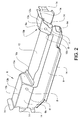
- the supporting element 6 is shown in more detail.
- the words top, low etc. will in this descripion refer to directions relative to the intended orientation of the member in a vehicle.
- the supporting element 6 is made from a piece of sheet metal being folded at multiple lines to have an elongated shape with a roughly trapezium shaped cross-section, as seen in fig 5 .
- the trapezium shape, with the short side up, gives a good stability to the supporting element.
- the supporting element 6 thus has two longitudinal side panels 9 and 10, the side panel 9 being folded at a blunt angle along a first folding line 11 in order to be adapted to fit a seat chassis (not shown).
- the two side panels 9 and 10 are united by a top panel 12, which is split in two top panel parts 12a and 12b, positioned at the opposite ends of the side panels 9 and 10, respectively.
- the split has been made by removing part of the sheet metal originally positioned between 12a and 12b, in a step in the manufacturing process.
- the reason for having a split top panel 12 will be given below.
- the top panel parts 12a and 12 b connects along second folding lines 13a and 13b to corresponding side panel parts parts 9a and 9b of the side panel 9, which, as is also the case with the side panel 10 correspondingly, has a part of the sheet metal removed, suitably in the same manufacturing removal step as described above, between the side panel parts 9a and 9b corresponding in position lengthwise to the part removed from the top panel.
- the supporting element 6 also is designed with welding tags 14 distributed along the lower rim of the side panels and at its outer end rims of side panel parts 9a and 9b and side panel 10.
- the welding tags 14 are of various shapes and are used for fixing the supporting element to the floor module and to the respective sill.
- a respective flap 15a and 15b are downfolded, the flaps having in turn a folded flap welding tag 16a and 16b at its lower end, respectively.
- the flap welding tags 16 are pointing in a direction against each other.
- the flap welding tags 16a and 16b are intended for the fixation of the body enforcing member 7 inside the supporting element 6 which will be described below.
- fig 3 the vehicle enforcing element 7 is shown.
- the enforcing element is stamped and to some extent folded out of a flat sheet metal piece to have an elongated shape with a substantially trapezium shaped cross-section as I shown in fig 6 .
- the trapezium shape gives a good stability to the enforcing element and also makes it easy to fit inside the supporting element 6.
- the enforcing element thus has an enforcing top panel 17 and two enforcing side panels 18 and 19, which at their low rim 20 are somewhat extended at the respective end in order to enlarge the welding area.
- the top panel 17 and the side panels 18 and 19 are connected via a double-folded section 21 and 22, respectively.
- the double-folded sections 21 and 22 help in further stabilising the enforcing element.
- the top panel 17 is designed with a recess 23, which also helps in stabilising the enforcing element.
- upwardly angled flaps 24 and 25 are arranged in connection with the outer rims of the enforcing top panel 17. The flaps 24 and 25 increase the ability of the enforcing element 7 to transfer crash forces from the inner sill to the centre tunnel when the vehicle is in a crash situation.
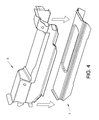
- fig 4 it is illustrated how the supporting element 6 and the enforcing element 7 are put together to form the vehicle body member 5.
- the supporting element 6 is entered on top of the enforcing element 7 to a position where the inside of the supporting element side panels 9 and 10 meet with the outside of the enforcing element side panels 18 and 19, as shown in fig 5 , which is a cross-section view of the two elements put together.
- the supporting element 6 and the enforcing element 7 is spot welded together to form a unit, ready to place and fix on to the vehicle floor module, as is shown in fig 1 and fig 6 , where the floor module, the inner sill and the centre tunnel are schematically shown.
- Spot-welding is preferrably done on both sides, welding supporting element side panel 9 and enforcing element side panel 19 and supporting element side panel 10 and enforcing element side panel 18 together, respectively, and also the flap welding tags 16a and 16b are welded to the enforcing element 7 top panel 17.
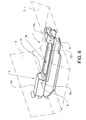
- fig 5 a cross-section of the vehicle body member is shown.
- the enforcing element 7 is fixed inside the supporting member 6 by spot welding (spots not shown). The spots are made where the respective side panels 9,19 and 10,18 meet and also where the flap welding tags 16 meet the top panel 17 of the enforcing element 7.
- the top panels 12a and 12b of the supporting element 7 is somewhat inclined compared to a fictitious line 21 drawn between the bottom rims of the supporting side panels 9 and 10, but the overall geometrics can be described as a trapezium cross-section, even if the side panel 9 is slightly folded.
- the reason for the inclination is that the top panel of the supporting element should be in line with the bottom of the seat chassis (not shown) to be able to have a good connection therebetween.
- fig 6 a more clear view of the vehicle body member than in fig 1 is shown. It can be seen that there is a stepped space 26 formed by part of the enforcing element top panel 17, above the recess 23 of the enforcing element 7, between the flaps 15a and 15b and under a top level defined by the supporting element top panel 12. This space can be used by rear seat passengers in the car for putting their feet while travelling in the car.
- the shape of the supporting and the enforcing element is not limited to what has been shown e.g. the cross-section of the elements can be of another shape with curved panels or even stepped panels as long as the enforcing panel is adapted to fit for fastening inside the supporting panel.
- the welding tags could be designed in alternative ways without changing the invention behind.
- the step 26 on top of the vehicle body member can be modified to adapt to the seat chassis design, still leaving comfortable footspace.
- the sheet metal used to make it can be chosen concerning thickness bearing in mind that it is made in a folding process and does not have to carry crash impact loads, while the design of the enforcing element including choice of the type of metal and material thickness can be made bearing in mind that the enforcing element does not have to have the heigt to support the seat chassis but shall have high stiffness to be able to resist side impact collision forces. This makes it possible to have the enforcing element manufactured by a stamping process which enables the end product to have high stiffness.
Landscapes
- Engineering & Computer Science (AREA)
- Transportation (AREA)
- Mechanical Engineering (AREA)
- Chemical & Material Sciences (AREA)
- Combustion & Propulsion (AREA)
- Aviation & Aerospace Engineering (AREA)
- Body Structure For Vehicles (AREA)
Abstract
Description
- The present invention relates to a vehicle body member for supporting a vehicle seat or a seat chassis and for resisting side impact collision forces, the vehicle body having a floor module with a centre tunnel and at least one sill.
- Modern standard passenger vehicles or cars have seats for 4 or 5 persons, 2 of them in the front. The two front seats normally comprises two separate chairs that are connected to the vehicle body floor between an outer sill, left and right respectively, and a centre tunnel. Most chairs or seats are adjustably arranged, i.e. they can be adjusted both up and down, back and forth, and they are also tiltable. The means for this is a chair chassis, which is fixed to the very seat and to the vehicle body floor at certain points, most often two in the front and two in the back. Since the chair with its chassis is often manufactured somewhere else than at the car plant and unnecessary time consuming work must be avoided, it is important that the vehicle body, which is welded together at the plant, have fixing points for the chair chassis that are very accurately positioned to meet the fixing points of the chair chassis. A common way of meeting this demand is to weld brackets to the body floor at predetermined positions while at the same time having tools that keep the different brackets in well defined positions relative each other during the welding process. It is also known to have a seat front bracket that extends transverse to the longitudinal direction of the vehicle body between an outer sill and a centre tunnel, having fixing points for both the left and the right side of the chair chassis. It is further known to have two seat rear brackets positioned behind the front seat bracket, one positioned at the respective outer sill and the other at the centre tunnel. Two separate brackets gives foot space for a rear seat passenger under the front seat. It is still known to have a single rear bracket, extending in a similar way to the front seat bracket transverse to the vehicle body direction between the outer sill and the centre tunnel. One simple way of making the seat brackets is by folding a piece of sheet metal to the desired form.
- In modern cars there is also a large demand for crash safety. Since the rear bracket is positioned inside the vehicle body B-pillar, it can strengthen the body resistance to side impact collisions. For this reason, it is known to produce the rear brackets (left and right vehicle body side) by stamping a sheet metal to the desired form instead of folding a sheet metal piece, since a bracket of that type with less or smaller flutes has better and more controlled behaviour properties in a crash situation.
- One problem to use a stamped bracket is that when considering crash resistance the wanted thickness of the sheet metal being used for the bracket contradicts the need for stampability. With modern car designs, especially for cars of the type SUV, the distance between the vehicle body floor and the fixing points of the vehicle chair chassis is higher than in older vehicles. This makes the stampability property demand for the sheet metall used in the brackets even higher and makes a design of a stamped bracket expensive and complicated, bearing in mind the need for thickness to meet the crash safety demand.
- Another problem, thinking of crash forces and the use of the seat brackets for helping secure the passengers inside the vehicle, is that there is a need for foot space for the rear seat passengers underneath the front seats. Since the rear seat consoles are positioned inside the B-pillars (left and right) the consoles often must have a shape that allows rear seat passengers to put their feet under the front seat, where the bracket is positioned. This is a factor that the designer of the bracket must bear in mind and consider because such a shape does not help when it comes to design for withstanding forces in its longitudinal direction.
- The problems with prior art discussed above is solved by a vehicle body member having a combination of a seat or seat chassis supporting element and a vehicle body enforcing element, the elements both being elongated and extending transverse to the longitudinal direction of the vehicle body under the at least one seat between the centre tunnel and one of the side sills, whereby the enforcing element is arranged lengthwise inside the supporting element and is carried in a fixed position by the supporting element. This combination allows the designer to choose a suitably high design for the supporting element to meet highly positioned seat chassis without having to compromise with demands on crash properties while at the same time the enforcing element can be designed to meet the demands for a stiff vehicle body. The fixing of the enforcing element inside the supporting elements solves the problem of accuracy for the seat chassis fixing points since when making the vehicle body there is only one member that has to be accurately positioned. The material in the supporting element and the enforcing element can be chosen independently to meet suitable production methods and costs. Also the accuracy of the positions of the fixing points for the seat or seat chassis is secured by having the supporting element accurately positioned while the enforcing member does not interfere, since it is fixed to the supporting element.
- In one advantageous embodiment of the invention the supporting element has a cross-section essentially in the shape of a trapezium, and that the enforcing element has a crossection essentially in the shape of a trapezium whereby the outer dimensions of the the enforcing element and the inner dimensions of the supporting element respectively are adapted for a spot-weldable contact when the enforcing element is in operable position on the inside of the supporting element
- In a further advantageous embodiment of the invention the enforcing element is lower than the supporting element allowing a free foot space for passengers to be defined above the enforcing element and below a top level defined by a top panel of the supporting element. This embodiment creates a comfortable foot space for rear seat passengers.
- Further advantages will be evident from the description of the embodiment shown in the drawings and will also be defined in the following claim set.
- The invention will in the following be described in connection with an example shown in the drawings on which
-
Fig 1 shows the position of a vehicle body member of the kind herein described when mounted on a vehicle floor module (the vehicle floor module shown in part only). -
Fig. 2 shows a chair supporting element comprised in the vehicle body member -
Fig 3 shows a vehicle body enforcing element comprised in the vehicle body member -
Fig 4 shows how the supporting element and the enforcing element are put together, -
Fig 5 shows in cross section the relative position between the supporting element and the enforcing element when combined and -
Fig 6 shows schematically how the vehicle body member fits to the vehicle floor module. - Partly shown in
fig. 1 is a floor module 1 of a typical passenger vehicle. The floor module has acentre tunnel 2 and a left,inner sill 3, the forward direction of the vehicle being in the direction of thearrow 4. The floor module has a topography which is designed to meet various demands but this is not of particular interest here, and for this reason it is not discussed in more detail. What is of interest is anelongated body member 5, extending between the left,inner sill 3 and thecentre tunnel 2 in a direction substantially transverse to the forward direction of the floor module. The body member comprises two elements, a seat or a seatchassis supporting element 6 and a vehiclebody enforcing element 7, the latter situated inside the supportingelement 6. The vehicle body member hasfixing points 8, positioned in order to meet accurately with corresponding fixing points of a seat or a seat chassis (not shown). The enforcingelement 7 is contained inside the supportingelement 6 and spot-welded to it, while the supporting element in turn is spot-welded to thefloor module 3. - In
fig 2 the supportingelement 6 is shown in more detail. The words top, low etc. will in this descripion refer to directions relative to the intended orientation of the member in a vehicle. The supportingelement 6 is made from a piece of sheet metal being folded at multiple lines to have an elongated shape with a roughly trapezium shaped cross-section, as seen infig 5 . The trapezium shape, with the short side up, gives a good stability to the supporting element. The supportingelement 6 thus has twolongitudinal side panels side panel 9 being folded at a blunt angle along afirst folding line 11 in order to be adapted to fit a seat chassis (not shown). The twoside panels top panel 12, which is split in twotop panel parts side panels split top panel 12 will be given below. Thetop panel parts second folding lines panel parts parts side panel 9, which, as is also the case with theside panel 10 correspondingly, has a part of the sheet metal removed, suitably in the same manufacturing removal step as described above, between theside panel parts element 6 also is designed withwelding tags 14 distributed along the lower rim of the side panels and at its outer end rims ofside panel parts side panel 10. Thewelding tags 14 are of various shapes and are used for fixing the supporting element to the floor module and to the respective sill. At the end rims of thetop panel parts respective flap flap welding tag flap welding tags body enforcing member 7 inside the supportingelement 6 which will be described below. - In
fig 3 thevehicle enforcing element 7 is shown. The enforcing element is stamped and to some extent folded out of a flat sheet metal piece to have an elongated shape with a substantially trapezium shaped cross-section as I shown infig 6 . The trapezium shape, with the short side up, gives a good stability to the enforcing element and also makes it easy to fit inside the supportingelement 6. The enforcing element thus has an enforcingtop panel 17 and two enforcingside panels low rim 20 are somewhat extended at the respective end in order to enlarge the welding area. Thetop panel 17 and theside panels section sections top panel 17 is designed with arecess 23, which also helps in stabilising the enforcing element. At the remote ends of the enforcingelement 7 upwardlyangled flaps top panel 17. Theflaps element 7 to transfer crash forces from the inner sill to the centre tunnel when the vehicle is in a crash situation. - In
fig 4 it is illustrated how the supportingelement 6 and the enforcingelement 7 are put together to form thevehicle body member 5. As shown, the supportingelement 6 is entered on top of the enforcingelement 7 to a position where the inside of the supportingelement side panels element side panels fig 5 , which is a cross-section view of the two elements put together. Then the supportingelement 6 and the enforcingelement 7 is spot welded together to form a unit, ready to place and fix on to the vehicle floor module, as is shown infig 1 andfig 6 , where the floor module, the inner sill and the centre tunnel are schematically shown. Spot-welding is preferrably done on both sides, welding supportingelement side panel 9 and enforcingelement side panel 19 and supportingelement side panel 10 and enforcingelement side panel 18 together, respectively, and also theflap welding tags element 7top panel 17. - In
fig 5 a cross-section of the vehicle body member is shown. The enforcingelement 7 is fixed inside the supportingmember 6 by spot welding (spots not shown). The spots are made where therespective side panels top panel 17 of the enforcingelement 7. - As can be seen in the
fig 5 , thetop panels element 7 is somewhat inclined compared to afictitious line 21 drawn between the bottom rims of the supportingside panels side panel 9 is slightly folded. The reason for the inclination is that the top panel of the supporting element should be in line with the bottom of the seat chassis (not shown) to be able to have a good connection therebetween. - In
fig 6 a more clear view of the vehicle body member than infig 1 is shown. It can be seen that there is a steppedspace 26 formed by part of the enforcing elementtop panel 17, above therecess 23 of the enforcingelement 7, between theflaps top panel 12. This space can be used by rear seat passengers in the car for putting their feet while travelling in the car. - The invention herein explained is not limited to what has been described in connection with the example shown in the drawings. The shape of the supporting and the enforcing element is not limited to what has been shown e.g. the cross-section of the elements can be of another shape with curved panels or even stepped panels as long as the enforcing panel is adapted to fit for fastening inside the supporting panel. Also the welding tags could be designed in alternative ways without changing the invention behind. Also the
step 26 on top of the vehicle body member can be modified to adapt to the seat chassis design, still leaving comfortable footspace. When designing the supporting element the sheet metal used to make it can be chosen concerning thickness bearing in mind that it is made in a folding process and does not have to carry crash impact loads, while the design of the enforcing element including choice of the type of metal and material thickness can be made bearing in mind that the enforcing element does not have to have the heigt to support the seat chassis but shall have high stiffness to be able to resist side impact collision forces. This makes it possible to have the enforcing element manufactured by a stamping process which enables the end product to have high stiffness.
Claims (10)
- A vehicle body member (5) for supporting at least one seat or seat chassis positioned in the vehicle body and for resisting side impact collision forces, the vehicle body having a floor module (1) with a tunnel (2) and at least one side sill (3), characterised in a combination of a seat or seat chassis supporting element (6) and a vehicle body enforcing element (7), the elements (6,7) both being elongated and extending transverse to the longitudinal direction of the vehicle body under the at least one seat between the tunnel (2) and the at least one side sill, whereby the enforcing element (7) is arranged lengthwise inside the supporting element (6) and is carried in a fixed position by the supporting element, which in turn is fixed to the floor module (1).
- A vehicle body member according to claim 1, characterised in that the supporting element (6) has a cross-section essentially in the shape of a trapezium, and that the enforcing element (7) has a crossection essentially in the shape of a trapezium whereby the outer dimensions of the the enforcing element and the inner dimensions of the supporting element respectively are adapted for a spot-weldable contact when the enforcing element is in operable position on the inside of the supporting element.
- A vehicle body member according to claim 1 or 2, characterised in that the enforcing element (7) is lower than the supporting element (6) allowing a free foot space for passengers to be defined above the enforcing element (7) and below a top level defined by a top panel (12) of the supporting element (6).
- A vehicle body member according to claim 2 or 3, whereby the supporting element (6) has a couple of side panels (9,10), characterised in that at least one of the supporting element side panels is folded outwardly.
- A vehicle body member according to claim 2 or 3, characterised in that the top panel (12a,b) of the supporting element (6) has an open part between two non-open end parts and that the side panels (9,10) of the supporting element have cut-out parts correspondingly positioned to the open part of the top panel (12a,b), thus allowing access to the free space between the supporting and the enforcing element 6,7).
- A vehicle body member according to any of the above claims, characterised in that the supporting element (6) is manufactured from a sheet metal part which is folded to have the essentially trapezium shaped cross-section.
- A vehicle body member according to any of the above claims, characterised in that the enforcing element (7) is stamped and then folded to its essentially trapezium shaped cross-sectionform.
- A vehicle body member according to any of the above claims, characterised in that the supporting element (6) is equipped with tags suitable for spotwelding to the vehicle body.
- A floor module for a passenger vehicle, comprising at least one vehicle body member (5) according to any of the claims 1 to 8.
- A passenger vehicle, comprising at least one body member (5) according to any of the claims 1 to 8.
Priority Applications (1)
| Application Number | Priority Date | Filing Date | Title |
|---|---|---|---|
| EP08102186A EP2096020B1 (en) | 2008-02-29 | 2008-02-29 | Vehicle body member |
Applications Claiming Priority (1)
| Application Number | Priority Date | Filing Date | Title |
|---|---|---|---|
| EP08102186A EP2096020B1 (en) | 2008-02-29 | 2008-02-29 | Vehicle body member |
Publications (2)
| Publication Number | Publication Date |
|---|---|
| EP2096020A1 true EP2096020A1 (en) | 2009-09-02 |
| EP2096020B1 EP2096020B1 (en) | 2011-06-22 |
Family
ID=39232867
Family Applications (1)
| Application Number | Title | Priority Date | Filing Date |
|---|---|---|---|
| EP08102186A Ceased EP2096020B1 (en) | 2008-02-29 | 2008-02-29 | Vehicle body member |
Country Status (1)
| Country | Link |
|---|---|
| EP (1) | EP2096020B1 (en) |
Cited By (8)
| Publication number | Priority date | Publication date | Assignee | Title |
|---|---|---|---|---|
| DE102009048335A1 (en) * | 2009-10-06 | 2011-04-07 | GM Global Technology Operations, Inc., Detroit | Seat cross beam for fastening seat to body undersurface of motor vehicle, has longitudinal profiles provided with ramp shaped connecting sections that are connected with transverse profile |
| CN103144683A (en) * | 2011-12-07 | 2013-06-12 | 丰田自动车株式会社 | Floor structure of vehicle |
| RU2563378C1 (en) * | 2013-04-15 | 2015-09-20 | Др. Инж. х.к. Ф. Порше Акциенгезелльшафт | Floor tunnel device assembly for vehicle body and floor assembly |
| US20160159406A1 (en) * | 2014-12-09 | 2016-06-09 | Ford Global Technologies, Llc | Vehicle body structure |
| CN108189713A (en) * | 2017-12-18 | 2018-06-22 | 合肥亿恒智能科技股份有限公司 | One kind is used for the fixed crossbeam assembly of automotive seat |
| CN112993457A (en) * | 2019-12-12 | 2021-06-18 | 通用汽车环球科技运作有限责任公司 | End stabilizer for high-voltage battery structural part |
| FR3119363A1 (en) * | 2021-01-29 | 2022-08-05 | Psa Automobiles Sa | Underbody structure in the event of a side impact |
| FR3164168A1 (en) * | 2024-07-05 | 2026-01-09 | Stellantis Auto Sas | CROSS BEAM FOR MOTOR VEHICLE UNDERBody STRUCTURE AND VEHICLE INCLUDING SUCH A CROSS BEAM |
Citations (3)
| Publication number | Priority date | Publication date | Assignee | Title |
|---|---|---|---|---|
| JPH08133131A (en) * | 1994-11-08 | 1996-05-28 | Nissan Motor Co Ltd | Vehicle cross member structure |
| JPH0924864A (en) * | 1995-07-12 | 1997-01-28 | Nissan Motor Co Ltd | Cross member structure |
| WO2007088303A1 (en) * | 2006-02-02 | 2007-08-09 | Peugeot Citroën Automobiles SA | Motor vehicle seat part cross member |
-
2008
- 2008-02-29 EP EP08102186A patent/EP2096020B1/en not_active Ceased
Patent Citations (3)
| Publication number | Priority date | Publication date | Assignee | Title |
|---|---|---|---|---|
| JPH08133131A (en) * | 1994-11-08 | 1996-05-28 | Nissan Motor Co Ltd | Vehicle cross member structure |
| JPH0924864A (en) * | 1995-07-12 | 1997-01-28 | Nissan Motor Co Ltd | Cross member structure |
| WO2007088303A1 (en) * | 2006-02-02 | 2007-08-09 | Peugeot Citroën Automobiles SA | Motor vehicle seat part cross member |
Cited By (14)
| Publication number | Priority date | Publication date | Assignee | Title |
|---|---|---|---|---|
| DE102009048335A1 (en) * | 2009-10-06 | 2011-04-07 | GM Global Technology Operations, Inc., Detroit | Seat cross beam for fastening seat to body undersurface of motor vehicle, has longitudinal profiles provided with ramp shaped connecting sections that are connected with transverse profile |
| CN103144683A (en) * | 2011-12-07 | 2013-06-12 | 丰田自动车株式会社 | Floor structure of vehicle |
| CN103144683B (en) * | 2011-12-07 | 2016-02-24 | 丰田自动车株式会社 | The floor panel structure of vehicle body |
| RU2563378C1 (en) * | 2013-04-15 | 2015-09-20 | Др. Инж. х.к. Ф. Порше Акциенгезелльшафт | Floor tunnel device assembly for vehicle body and floor assembly |
| US9205878B2 (en) | 2013-04-15 | 2015-12-08 | Dr. Ing. H.C.F. Porsche Aktiengesellschaft | Tunnel arrangement for a floor assembly of a vehicle body, and a floor assembly |
| US9487243B2 (en) * | 2014-12-09 | 2016-11-08 | Ford Global Technologies, Llc | Vehicle body structure |
| US20160159406A1 (en) * | 2014-12-09 | 2016-06-09 | Ford Global Technologies, Llc | Vehicle body structure |
| CN108189713A (en) * | 2017-12-18 | 2018-06-22 | 合肥亿恒智能科技股份有限公司 | One kind is used for the fixed crossbeam assembly of automotive seat |
| CN108189713B (en) * | 2017-12-18 | 2023-12-05 | 合肥亿恒智能科技有限公司 | Beam assembly for fixing automobile seat |
| CN112993457A (en) * | 2019-12-12 | 2021-06-18 | 通用汽车环球科技运作有限责任公司 | End stabilizer for high-voltage battery structural part |
| US11607962B2 (en) | 2019-12-12 | 2023-03-21 | GM Global Technology Operations LLC | High voltage battery structural member end stabilizer |
| CN112993457B (en) * | 2019-12-12 | 2023-11-03 | 通用汽车环球科技运作有限责任公司 | End stabilizer for high-voltage battery structural part |
| FR3119363A1 (en) * | 2021-01-29 | 2022-08-05 | Psa Automobiles Sa | Underbody structure in the event of a side impact |
| FR3164168A1 (en) * | 2024-07-05 | 2026-01-09 | Stellantis Auto Sas | CROSS BEAM FOR MOTOR VEHICLE UNDERBody STRUCTURE AND VEHICLE INCLUDING SUCH A CROSS BEAM |
Also Published As
| Publication number | Publication date |
|---|---|
| EP2096020B1 (en) | 2011-06-22 |
Similar Documents
| Publication | Publication Date | Title |
|---|---|---|
| EP2096020B1 (en) | Vehicle body member | |
| CN100352719C (en) | Car floor beam structure | |
| US7434871B2 (en) | Lower vehicle body structure of vehicle | |
| US8292356B2 (en) | Lower vehicle-body structure of vehicle | |
| US5954390A (en) | Vehicle dynamic side impact system | |
| US7185917B2 (en) | Knee bolster structure | |
| US20130161981A1 (en) | Motor vehicle body with reinforcing structure | |
| US7431338B2 (en) | Impact absorbing knee bolster | |
| EP1916149A2 (en) | Frame structure of seatback for vehicle | |
| JP4875559B2 (en) | Body frame structure | |
| US20120119542A1 (en) | Car body with reinforcing structure | |
| US20120119544A1 (en) | Car body with reinforcing structure | |
| CN107206877A (en) | Resist the reinforcing vehicle doorn of side impact | |
| JP2010173634A (en) | Vehicle roof support pillar assembly | |
| CN102481872A (en) | Seat assembly with impact load transfer structure | |
| KR101601521B1 (en) | Vehicle door reinforcement insert | |
| JP5937110B2 (en) | Assembly for mounting automotive steering columns | |
| CN102476656A (en) | Rear structure for vehicle body | |
| US10926806B2 (en) | Vehicle torque box assembly | |
| JP4923406B2 (en) | Body front structure | |
| JP2009012634A (en) | Vehicle body structure | |
| JP2008302911A (en) | Vehicle body structure | |
| JP4838604B2 (en) | Rear side member structure of the vehicle | |
| CN117284379A (en) | Body structure and vehicle | |
| JPH07149258A (en) | Car side body structure |
Legal Events
| Date | Code | Title | Description |
|---|---|---|---|
| PUAI | Public reference made under article 153(3) epc to a published international application that has entered the european phase |
Free format text: ORIGINAL CODE: 0009012 |
|
| AK | Designated contracting states |
Kind code of ref document: A1 Designated state(s): AT BE BG CH CY CZ DE DK EE ES FI FR GB GR HR HU IE IS IT LI LT LU LV MC MT NL NO PL PT RO SE SI SK TR |
|
| AX | Request for extension of the european patent |
Extension state: AL BA MK RS |
|
| 17P | Request for examination filed |
Effective date: 20091104 |
|
| 17Q | First examination report despatched |
Effective date: 20091127 |
|
| AKX | Designation fees paid |
Designated state(s): DE GB SE |
|
| GRAP | Despatch of communication of intention to grant a patent |
Free format text: ORIGINAL CODE: EPIDOSNIGR1 |
|
| GRAS | Grant fee paid |
Free format text: ORIGINAL CODE: EPIDOSNIGR3 |
|
| GRAA | (expected) grant |
Free format text: ORIGINAL CODE: 0009210 |
|
| AK | Designated contracting states |
Kind code of ref document: B1 Designated state(s): DE GB SE |
|
| REG | Reference to a national code |
Ref country code: GB Ref legal event code: FG4D |
|
| REG | Reference to a national code |
Ref country code: DE Ref legal event code: R096 Ref document number: 602008007735 Country of ref document: DE Effective date: 20110804 |
|
| RAP2 | Party data changed (patent owner data changed or rights of a patent transferred) |
Owner name: VOLVO CAR CORPORATION |
|
| REG | Reference to a national code |
Ref country code: SE Ref legal event code: TRGR |
|
| REG | Reference to a national code |
Ref country code: GB Ref legal event code: 732E Free format text: REGISTERED BETWEEN 20111020 AND 20111025 |
|
| REG | Reference to a national code |
Ref country code: DE Ref legal event code: R081 Ref document number: 602008007735 Country of ref document: DE Owner name: VOLVO CAR CORP., SE Free format text: FORMER OWNER: FORD GLOBAL TECHNOLOGIES, LLC, DEARBORN, MICH., US Effective date: 20111212 |
|
| PLBE | No opposition filed within time limit |
Free format text: ORIGINAL CODE: 0009261 |
|
| STAA | Information on the status of an ep patent application or granted ep patent |
Free format text: STATUS: NO OPPOSITION FILED WITHIN TIME LIMIT |
|
| 26N | No opposition filed |
Effective date: 20120323 |
|
| REG | Reference to a national code |
Ref country code: DE Ref legal event code: R097 Ref document number: 602008007735 Country of ref document: DE Effective date: 20120323 |
|
| PGFP | Annual fee paid to national office [announced via postgrant information from national office to epo] |
Ref country code: GB Payment date: 20190206 Year of fee payment: 12 |
|
| PGFP | Annual fee paid to national office [announced via postgrant information from national office to epo] |
Ref country code: SE Payment date: 20190228 Year of fee payment: 12 |
|
| GBPC | Gb: european patent ceased through non-payment of renewal fee |
Effective date: 20200229 |
|
| PG25 | Lapsed in a contracting state [announced via postgrant information from national office to epo] |
Ref country code: GB Free format text: LAPSE BECAUSE OF NON-PAYMENT OF DUE FEES Effective date: 20200229 Ref country code: SE Free format text: LAPSE BECAUSE OF NON-PAYMENT OF DUE FEES Effective date: 20200301 |
|
| P01 | Opt-out of the competence of the unified patent court (upc) registered |
Effective date: 20231212 |
|
| PGFP | Annual fee paid to national office [announced via postgrant information from national office to epo] |
Ref country code: DE Payment date: 20240123 Year of fee payment: 17 |
|
| REG | Reference to a national code |
Ref country code: DE Ref legal event code: R119 Ref document number: 602008007735 Country of ref document: DE |
|
| PG25 | Lapsed in a contracting state [announced via postgrant information from national office to epo] |
Ref country code: DE Free format text: LAPSE BECAUSE OF NON-PAYMENT OF DUE FEES Effective date: 20250902 |