EP2095900A1 - Gearing apparatus, and gear working machine - Google Patents
Gearing apparatus, and gear working machine Download PDFInfo
- Publication number
- EP2095900A1 EP2095900A1 EP08704461A EP08704461A EP2095900A1 EP 2095900 A1 EP2095900 A1 EP 2095900A1 EP 08704461 A EP08704461 A EP 08704461A EP 08704461 A EP08704461 A EP 08704461A EP 2095900 A1 EP2095900 A1 EP 2095900A1
- Authority
- EP
- European Patent Office
- Prior art keywords
- gear
- workpiece
- rotational phase
- sensor
- matching device
- Prior art date
- Legal status (The legal status is an assumption and is not a legal conclusion. Google has not performed a legal analysis and makes no representation as to the accuracy of the status listed.)
- Granted
Links
Images



Classifications
-
- B—PERFORMING OPERATIONS; TRANSPORTING
- B23—MACHINE TOOLS; METAL-WORKING NOT OTHERWISE PROVIDED FOR
- B23F—MAKING GEARS OR TOOTHED RACKS
- B23F23/00—Accessories or equipment combined with or arranged in, or specially designed to form part of, gear-cutting machines
-
- B—PERFORMING OPERATIONS; TRANSPORTING
- B23—MACHINE TOOLS; METAL-WORKING NOT OTHERWISE PROVIDED FOR
- B23F—MAKING GEARS OR TOOTHED RACKS
- B23F23/00—Accessories or equipment combined with or arranged in, or specially designed to form part of, gear-cutting machines
- B23F23/02—Loading, unloading or chucking arrangements for workpieces
-
- B—PERFORMING OPERATIONS; TRANSPORTING
- B23—MACHINE TOOLS; METAL-WORKING NOT OTHERWISE PROVIDED FOR
- B23F—MAKING GEARS OR TOOTHED RACKS
- B23F23/00—Accessories or equipment combined with or arranged in, or specially designed to form part of, gear-cutting machines
- B23F23/12—Other devices, e.g. tool holders; Checking devices for controlling workpieces in machines for manufacturing gear teeth
-
- B—PERFORMING OPERATIONS; TRANSPORTING
- B23—MACHINE TOOLS; METAL-WORKING NOT OTHERWISE PROVIDED FOR
- B23F—MAKING GEARS OR TOOTHED RACKS
- B23F23/00—Accessories or equipment combined with or arranged in, or specially designed to form part of, gear-cutting machines
- B23F23/12—Other devices, e.g. tool holders; Checking devices for controlling workpieces in machines for manufacturing gear teeth
- B23F23/1218—Checking devices for controlling workpieces in machines for manufacturing gear teeth
Definitions
- the present invention relates to a gear matching device which performs gear matching so as to establish a rotational phase relationship between a rotary tool and a gear to be machined in which the rotary tool and the gear can mesh with each other, and also relates to a gear machining apparatus using the gear matching device.
- Gear machining apparatuses such as gear grinders and hobbing machines, have heretofore been offered as tools for machining gears by using rotary tools.
- a gear machining apparatus a rotary tool and a gear to be machined (hereinafter referred to simply as a "gear" in the description) are synchronously controlled respectively by separate drive motors, and gear machining is then performed by causing the rotary tool and the gear to mesh with each other.
- a "gear matching" process is performed before the rotary tool and the gear are caused to mesh with each other.
- the gear matching process is performed so as to establish a rotational phase relationship between the rotary tool and the gear in which tooth tips (crests) and tooth spaces (troughs) of the rotary tool can mesh with tooth tips (crests) and tooth spaces (troughs) of the gear.
- the rotational phases respectively of the rotary tool and the gear are firstly detected by using a contact sensor such as a touch probe, or a non-contact sensor such as a proximity sensor. On the basis of the detection results, the offset between these rotational phases is corrected, so that the rotational phase of the rotary tool and the rotational phase of the gear are adjusted.
- Patent Document 1 discloses such a gear matching device.
- this gear matching device a tooth tip and a tooth space of a gear are read by using a sensor, while the rotations respectively of the rotary tool and the gear are determined. As a result, gear matching can be performed.
- Patent Document 1 Japanese Patent Application Laid-open Publication No. 2004-25333
- the sensor for detecting the rotational phase of a gear is provided on the side of a rotary tool, that is, on the side of a column for rotatably supporting the rotary tool. For this reason, the gear matching operation is complicated, thus leading to an increase in time taken for the gear matching.
- the gear matching operation is performed in the conventional gear matching device.
- the rotational phase of a gear is detected by using a sensor, it is necessary to withdraw a rotary tool once to a position where the rotary tool does not exert an adverse effect on the detection of the sensor.
- the time taken for the gear matching operation is increased due to the reciprocation of the rotary tool between its machining position and its withdrawal position, and also due to the reciprocation of the sensor between its detecting position and its withdrawal position.
- An object of the present invention is to provide a gear matching device capable of shortening time taken for the gear matching, and also to provide a gear machining apparatus using the gear matching device.
- a first invention for solving the above-described problems provides a gear matching device which performs gear matching to establish a rotational phase relationship between a rotary tool and a gear in which the rotary tool and the gear can mesh with each other, before gear machining is performed by causing the rotary tool and the gear to mesh with each other, and by then relatively rotating the rotary tool and the gear.
- the gear matching device is characterized by including workpiece holding means and rotational phase detecting means.
- the workpiece holding means is supported to be movable in the axial direction of the gear, and presses the gear against workpiece rotating means so as to rotatably hold the gear.
- the workpiece rotating means rotates the gear about the axis thereof.
- the rotational phase detecting means is provided to the workpiece holding means, and faces the gear to detect the rotational phase thereof when the workpiece holding means holds the gear.
- a second invention for solving the above-described problems provides the gear matching device according to the first invention with the following characteristics.
- the rotational phase detecting means is disposed on the opposite side of the gear to the rotary tool.
- a third invention for solving the above-described problems provides the gear matching device according to the first invention with the following characteristics.
- the gear matching device further includes withdrawing means which withdraws the rotational phase detecting means from a detecting position where the rotational phase detecting means detects the rotational phase of the gear.
- a fourth invention for solving the above-described problem provides the gear matching device according to any one of the first to third inventions with the following characteristics.
- the gear matching device further includes machining error absorbing means which absorbs a machining error in the axial direction of the gear when the workpiece holding means holds the gear.
- a fifth invention for solving the above-described problems provides a gear machining apparatus characterized by including the gear matching device according to any one of the first to fourth inventions.
- the gear matching device performs gear matching so as to establish a rotational phase relationship between a rotary tool and a gear in which the rotary tool and the gear can mesh with each other, before gear machining is performed by causing the rotary tool and the gear to mesh with each other, and by then relatively rotating the rotary tool and the gear.
- the gear matching device includes workpiece holding means and rotational phase detecting means.
- the workpiece holding means is supported to be movable in the axial direction of the gear, and presses the gear against workpiece rotating means so as to rotatably hold the gear.
- the workpiece rotating means rotates the gear about the axis thereof.
- the rotational phase detecting means is provided to the workpiece holding means, and faces the gear to detect the rotational phase thereof when the workpiece holding means holds the gear. Accordingly, it is possible to detect the rotational phase by using the rotational phase detecting means, while the work holding means holds the gear. As a result, time taken for the gear matching can be shortened.
- the rotational phase detecting means is disposed on the opposite side of the gear to the rotary tool. Accordingly, since the rotational phase detecting means does not interfere with the gear matching operation of the rotary tool, the operation of the rotational phase detecting means can be simplified. Concurrently, since chips of the gear are not attached to the rotational phase detecting means, the rotational phase detecting means can be prevented from being damaged.
- the gear matching device further includes withdrawing means which withdraws the rotational phase detecting means from the detecting position where the rotational phase detecting means detects the rotational phase of the gear. Accordingly, the rotational phase detecting means does not interfere with the gear matching operation of the rotary tool. This makes it possible to simplify the operation of the rotational phase detecting means. Concurrently, since chips of the gear can be prevented from being attached to the rotational phase detecting means, it is possible to prevent the rotational phase detecting means from being damaged.
- the gear matching device according to any one of the first to third inventions further includes machining error absorbing means which absorbs a machining error in the axial direction of the gear when the workpiece holding means holds the gear.
- machining error absorbing means which absorbs a machining error in the axial direction of the gear when the workpiece holding means holds the gear.
- the gear machining apparatus includes the gear matching device according to any one of the first to fourth inventions.
- the gear machining apparatus includes the gear matching device which performs gear matching so as to establish a rotational phase relationship between a rotary tool and a gear in which the rotary tool and the gear can mesh with each other, before gear machining is performed by causing the rotary tool and the gear to mesh with each other, and by then relatively rotating the rotary tool and the gear.
- the gear matching device also includes workpiece holding means and rotational phase detecting means.
- the workpiece holding means is supported to be movable in the axial direction of the gear.
- the workpiece holding means presses the gear against workpiece rotating means so as to rotatably hold the gear.
- the workpiece rotating means rotates the gear about the axis thereof.
- the rotational phase detecting means is provided to the workpiece holding means.
- the rotational phase detecting means faces the gear to detect the rotational phase thereof, when the workpiece holding means holds the gear.
- the rotational phase detecting means is disposed on the opposite side of the gear to the rotary tool.
- the gear matching device includes withdrawing means which withdraws the rotational phase detecting means from a detecting position where the rotational phase detecting means detects the rotational phase of the gear.
- the gear matching device includes machining error absorbing means which absorbs a machining error in the axial direction of the gear when the workpiece holding means holds the gear.
- Fig. 1 shows a side view of chief part of a gear grinder including a gear matching device according to a first embodiment of the present invention.
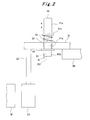
- Fig. 2 shows a schematic view of an attachment structure of a sensor.
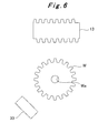
- Fig. 3 shows a positional relation of a grindstone and the sensor with respect to a workpiece.
- a column 12 is supported on a bed 11 of a gear grinder 1 that is a gear machining apparatus.
- the column 12 can be moved in the X-axis direction (the horizontal direction).
- a grindstone (rotary tool) 13 is supported on a front face of the column 12 so as to be rotatable about the horizontal axis.
- the grindstone 13 has a cylindrical shape, and a helical thread is formed on the outer peripheral surface of the grindstone 13.
- the grindstone 13 is supported to be movable in the Y-axis direction (the horizontal direction) and in the Z-axis direction (the vertical direction) with respect to the column 12, and concurrently to be revolvable in the A direction.
- the grindstone 13 is caused to mesh with a gear-shaped workpiece (gear to be machined) W, which will be described later, so that the gear grinding is carried out.
- a counter column 14 stands on the bed 11 to face the front face of the column 12.
- a guide member 15 is attached to a front face, facing the column 12, of the counter column 14.
- a tail stock 16 is supported on the guide member 15 to ascend and descend in the Z-axis direction.
- a tail stock center 17 having a substantially conical shape is supported on the lower end of the tail stock 16 to be rotatable about the vertical axis with respect to the tail stock 16.
- a discoidal rotary table (workpiece rotating means) 18 is supported on the bed 11 to be rotatable in the C direction (about the vertical axis).
- An attachment jig 19 having a substantially conical shape is detachably supported on the upper portion of the rotary table 18. Moreover, the workpiece W may be attached to, and detached from, the upper portion of the attachment jig 19.
- the center axis of the tail stock center 17, the center axis of the rotary table 18, and the center axis of the attachment jig 23 are arranged on the same axis. This arrangement makes it possible to hold the workpiece W in the following manner.
- the tail stock 16 is lowered toward the workpiece W loaded on the attachment jig 23, the tail stock center 17 is fitted into a center hole Wa (see Fig. 3 ) of the workpiece W, so that the workpiece W is held.
- the workpiece W thus held can be rotated in the C direction along with the tail stock center 17 and the attachment jig 19.
- a step portion 16a is formed in a part, on the counter column 14 (the guide member 15) side, of the tail stock 16.
- a rod 41 is attached, at the upper end thereof, to the step portion 16a of the tail stock 16.
- a sensor (rotational phase detecting means) 33 is supported on the lower end of the rod 41 with a supporting plate 31 and a supporting rod 32 in between.
- the sensor 33 is a non-contact sensor, such as a proximity sensor, for detecting the rotational phase of the workpiece W.
- a through hole 31a is formed in the supporting plate 31, and ring members 34 are provided respectively on the upper and lower portions of the through hole 31a.
- the rod 41 includes a large-diameter portion 41a, a small-diameter portion 41b, and a flange portion 41c.
- the large-diameter portion 41a is formed on the upper end side of the rod 41, while the small-diameter portion 41b is formed on the lower end side thereof to have a diameter smaller than that of the large-diameter portion 41a.
- the flange portion 41c is formed between the large-diameter portion 41a and the small-diameter portion 41b.
- the small-diameter portion 41b of the rod 41 penetrates the ring members 34 and the through hole 31a of the supporting plate 31 so as to be slidably supported therein.
- a spring 35 is disposed in a contracted state on the outer side of the small-diameter portion 41b, at a position between the flange portion 41c of the rod 41 and the ring member 34 on the upper side. Accordingly, the supporting plate 31 is biased downward with respect to the rod 41 by the biasing force of the spring 35.
- the sensor 33 is supported on one end of the supporting plate 31 with the above-described supporting rod 32 in between.
- a stopper 36 is disposed on the lower side of the other end of the supporting plate 31 while being supported on a lower portion of the front face of the counter column 14.
- the supporting plate 31 provided to the tail stock 16 is caused to abut on the stopper 36.
- the lower limit of the position of the tail stock 16 is thus set in this manner.
- the lower end of the rod 41 (the small-diameter portion 41b) is disposed at a descending reference position R, while the sensor 33 is disposed to face the held workpiece W.
- the movement of the column 12 in the X-axis direction; the movement of the grindstone 13 in the Y- and Z-axis directions as well as the swing and rotational drive thereof in the A direction; the ascending and descending of the tale stock 16 in the Z-axis direction; the rotational drive of the table 18 (the workpiece W) in the C direction; the detection of the rotational phase by the sensor 33; and the like are controlled by an unillustrated NC (numerical control) device.
- NC numbererical control
- the supporting plate 31, the supporting rod 32, the spring 35, the stopper 36, the rod 41, and the like constitute machining error absorbing means.
- the workpiece W is loaded onto the attachment jig 19, and then the tail stock 16 is lowered.
- the lowering of the tail stock 16 causes the supporting plate 31 to abut on the stopper 36, so that the tail stock 16 is disposed at the lower limit position.
- the tail stock center 17 is fitted into a center hole Wa of the workpiece W so as to hold the workpiece W, and concurrently the sensor 33 is disposed at the detecting position where the sensor 33 faces the workpiece W thus held.
- the rotary table 18 is rotated in a state where the sensor 33 is disposed at the detecting position, and the position of a first tooth tip (crest) of the workpiece W is measured. Thereafter, the rotary table 18 is rotated in the opposite direction, and the position of a second tooth tip next to the first tooth tip is measured. On the basis of the results of these measurements, the rotational phase in the C direction between these first and second tooth tips is detected.
- the NC device is caused to calculate the rotational phase in the C direction in a first tooth space (trough) between the first and second tooth tips of the workpiece W, from the detected rotational phase in the C direction between these tooth tips.
- the rotational phase in the C direction in a second tooth space, on the grindstone 13 side, of the workpiece W is calculated from: the calculated rotational phase in the C direction in the first tooth space, facing the sensor 33, of the workpiece W; the specifications (the number of teeth, the helix angle, and the like) of the workpiece W; the detection height of the sensor 33 for the workpiece W; the sensor angle (the relative rotational angle in the C direction from the grindstone 13 side), and the like.
- the amount of offset of the calculated rotational phase in the C direction in the tooth space, on the grindstone 13 side, of the workpiece W with respect to the grindstone 13 is obtained.
- the workpiece W is rotated for correction by the amount of offset of the rotational phase, so that the gear matching of the grindstone 13 with the workpiece W is carried out.
- the rotation of the grindstone 13 is synchronized with the rotation of the rotary table 18 in the C direction.
- the column 12 is moved in the X-axis direction, while the grindstone 13 is moved in the Y-and Z-axis directions as well as being rotated in the A direction.
- the grindstone 13 is caused to mesh with the workpiece W, so that the grinding is performed on the workpiece W.
- a minute machining error sometimes occurs in the workpiece W.
- a workpiece is rotated in the C direction about the vertical axis to be ground as described above.
- a machining error occurs in the height dimension, that is, in the face width, of the workpiece
- a variation occurs in the detecting position of the sensor in the Z-axis direction.
- the position cannot be detected with a high accuracy.
- the spring 35 is disposed between the supporting plate 31 and the rod 41.
- the spring 35 allows the sensor 33 to be disposed always at the same position in the Z-axis direction even when a machining error occurs in the height direction of the workpiece W.
- the lower limit position of the tail stock 16 is changed, by the increase in the height dimension, slightly upward of a position at the time when a workpiece is machined to have the predetermined dimension.
- the lower end of the rod 41 is lowered only to an upper reference position R1 positioned above the descending reference position R.
- the supporting plate 31 is biased downward with respect to the rod 41 by the biasing force of the spring 35, the supporting plate 31 abuts on the stopper 36.
- the senor 33 is disposed at the same position in the Z-axis direction as that in the case where a workpiece is machined to have a height dimension equivalent to the predetermined dimension.
- the lower limit position of the tail stock 16 is changed, by the decrease in the height dimension, slightly downward of the position at the time when a workpiece is machined to have the predetermined dimension.
- the supporting plate 31 abuts on the stopper 36, and concurrently the lower end of the rod 41 is lowered, against the biasing force of the spring 35, to a lower reference position R2 positioned below the descending reference position R.
- the lowering of the supporting plate 31 is restricted by the stopper 36, but only the rod 41 is lowered.
- the senor 33 is disposed at the same position in the Z-axis direction as that in the case where a workpiece is machined to have a height dimension equivalent to the predetermined dimension.
- the detecting position of the sensor 33 can be kept constant in the Z-axis direction.
- the sensor 33 is supported on the tail stock 16, it is unnecessary to withdraw the grindstone 13 even during the detection by the sensor 33, when the gear matching operation is carried out. As a result, time taken for the gear matching operation can be shortened.
- the sensor 33 is provided on the opposite side of the workpiece W to the grindstone 13. With this structure, the distance from the grindstone 13 to the sensor 33 can be made longer. As a result, the sensor 33 is prevented from being damaged by chips of the workpiece W, or by the feeding and splashing of a coolant, at the time of grinding.
- the supporting of the sensor 33 on the tail stock 16 makes it possible to detect the rotational phase of the workpiece W by using the sensor 33 while causing the tail stock 16 to hold the workpiece W. As a result, the time taken for the gear matching can be shortened.
- the sensor 33 since the sensor 33 is disposed on the opposite side of the workpiece W to the grindstone 13, the sensor 33 does not interfere with the gear matching operation of the grindstone 13. This makes it possible to simplify the operation, and to thus further shorten the time taken for the gear matching. Additionally, since the distance from the grindstone 13 to the sensor 33 can be kept sufficient, it is possible to prevent the sensor 33 from being damaged by chips of the workpiece W, or by the feeding and splashing of the coolant, at the time of grinding.
- the disposing of the spring 35 between the supporting plate 31 and the rod 41 provides the following effect. Specifically, even when a machining error occurs in the height dimension of the workpiece W, it is possible to absorb the machining error. Accordingly, the sensor 33 can be disposed constantly at the same detecting position. As a result, the rotational phase can be detected with a high accuracy.
- Fig. 4 shows a side view of chief part of a gear grinder including a gear matching device according to a second embodiment of the present invention.
- Fig 5 shows a schematic view of an attachment structure of a sensor.
- Fig. 6 shows a positional relation of a grindstone and the sensor with respect to a workpiece. Note that, in the following descriptions, components having the same structures and functions as those described in the first embodiment will be denoted by the same reference numerals, and the same descriptions as those made in the first embodiment will be omitted.
- a cylinder 51 is provided on the side face of the tail stock 16 in a gear grinder 2, which is a gear machining apparatus.
- the cylinder 51 is provided with a rod 52 that slides in the Z-axis direction.
- the sensor 33 is supported on the lower end of the rod 52 with the supporting plate 31 and the supporting rod 32 in between.
- the rod 52 includes a large-diameter portion 52a, a small-diameter portion 52b, and a flange portion 52c.
- the large-diameter portion 52a is formed on the upper end side of the rod 52, while the small-diameter portion 52b is formed on the lower end side thereof to have a diameter smaller than that of the large-diameter portion 52a.
- the flange portion 52c is formed between the large-diameter portion 52a and the small-diameter portion 52b.
- the small-diameter portion 52b of the rod 52 penetrates the ring members 34 and the through hole 31a of the supporting plate 31 so as to be slidably supported therein.
- the spring 35 is disposed in a contracted state on the outer side of the small-diameter portion 52b, at a position between the flange portion 52c of the rod 52 and the ring member 34 on the upper side. Accordingly, the supporting plate 31 is biased downward with respect to the rod 52 by the biasing force of the spring 35.
- the supporting plate 31 provided to the tail stock 16 is caused to abut on the stopper 36.
- the lower limit of the position of the tail stock 16 is thus set in this manner.
- the lower end of the rod 52 (the small-diameter portion 52b) is disposed at the descending reference position R, while the sensor 33 is disposed to face the held workpiece W.
- the sensor 33 is moved between a detecting position S1 and a withdrawal position S2 by driving the cylinder 51 to expand and contract the rod 52.
- the movement of the column 12 in the X-axis direction; the movement of the grindstone 13 in the Y- and Z-axis directions as well as the swing and rotational drive thereof in the A direction; the ascending and descending of the tail stock 16 in the Z-axis direction; the rotational drive of the table 18 (the workpiece W) in the C direction; the detection of the rotational phase by the sensor 33; the drive of the cylinder 51; and the like are controlled by an unillustrated NC device. In other words, the controlling of these operations makes it possible to perform the grinding on the workpiece W.
- the supporting plate 31, the supporting rod 32, the spring 35, the stopper 36, the cylinder 51, the rod 52, and the like constitute machining error absorbing means.
- the workpiece W is loaded onto the attachment jig 19, and then the tail stock 16 is lowered in a state where the rod 52 of the cylinder 51 is extended.
- the lowering of the tail stock 16 causes the supporting plate 31 to abut on the stopper 36, so that the tail stock 16 is disposed at the lower limit position.
- the tail stock center 17 is fitted into the center hole Wa of the workpiece W so as to hold the workpiece W, and concurrently the sensor 33 is disposed at the detecting position S1 where the sensor 33 faces the workpiece W thus held.
- the rotary table 18 is rotated in a state where the sensor 33 is disposed at the detecting position S1, and the position of a first tooth tip (crest) of the workpiece W is measured. Thereafter, the rotary table 18 is rotated in the opposite direction, and the position of a second tooth tip next to the first tooth tip is measured. On the basis of the results of these measurements, the rotational phase in the C direction between these first and second tooth tips is detected.
- the NC device is caused to calculate the rotational phase in the C direction in a tooth space (trough) between the first and second tooth tips of the workpiece W, from the detected rotational phase in the C direction between these tooth tips.
- the rotational phase in the C direction in a tooth space, on the grindstone 13 side, of the workpiece W is calculated from: the calculated rotational phase in the C direction in the tooth space, facing the sensor 33, of the workpiece W; the specifications (the number of teeth, the helix angle, and the like) of the workpiece W; the detection height of the sensor 33 for the workpiece W; the sensor angle (the relative rotational angle in the C direction from the grindstone 13 side), and the like.
- the amount of offset of the calculated rotational phase in the tooth space, on the grindstone 13 side, of the workpiece W with respect to the grindstone 13 is obtained.
- the workpiece W is rotated for correction by the amount of offset of the rotational phase, so that the gear matching of the grindstone 13 with the workpiece W is carried out.
- the sensor 33 is raised from the detecting position S1 to the withdrawal position S2 by driving the cylinder 51 to contract the rod 52. Then, the rotation of the grindstone 13 is synchronized with the rotation of the rotary table 18 in the C direction. At the same time, the column 12 is moved in the X-axis direction, while the grindstone 13 is moved in the Y- and Z-axis directions as well as being rotated in the A direction. As a result, the grindstone 13 is caused to mesh with the workpiece W, so that the grinding is performed on the workpiece W.
- a minute machining error sometimes occurs in the workpiece.
- the workpiece is rotated in the C direction about the vertical axis to be ground as described above, when a machining error occurs in the height dimension, that is, in the face width, of the workpiece, a variation occurs in the detecting position S1 of the sensor in the Z-axis direction. As a result, the position cannot be detected with a high accuracy.
- the spring 35 is disposed between the supporting plate 31 and the rod 52.
- the spring 35 allows the sensor 33 to be disposed always at the same position in the Z-axis direction even when a machining error occurs in the height direction of the workpiece W.
- the lower limit position of the tail stock 16 is changed, by the increase in the dimension, slightly upward of a position at the time when a workpiece is machined to have the predetermined dimension.
- the lower end of the rod 52 is lowered only to an upper reference position R1 positioned above the descending reference position R.
- the supporting plate 31 is biased downward with respect to the rod 52 by the biasing force of the spring 35, the supporting plate 31 abuts on the stopper 36.
- the senor 33 is disposed at the same position in the Z-axis direction as that in the case where a workpiece is machined to have a height dimension equivalent to the predetermined dimension.
- the lower limit position of the tail stock 16 is changed, by the decrease in the dimension, slightly downward of the position at the time when a workpiece is machined to have the predetermined dimension.
- the supporting plate 31 abuts on the stopper 36, and concurrently the lower end of the rod 52 is lowered, against the biasing force of the spring 35, to a lower reference position R2 positioned below the descending reference position R.
- the lowering of the supporting plate 31 is restricted by the stopper 36, but only the rod 52 is lowered.
- the senor 33 is disposed at the same position in the Z-axis direction as that in the case where a workpiece is machined to have a height dimension equivalent to the predetermined dimension.
- the detecting position S1 of the sensor 33 can be kept constant in the Z-axis direction.
- the sensor 33 is supported on the tail stock 16, it is unnecessary to withdraw the grindstone 13 even during the detection by the sensor 33, when the gear matching operation is carried out. As a result, time taken for the gear matching operation can be shortened. Moreover, since the sensor 33 having completed the detection of rotational phase is raised to the withdrawal position S2, the distance from the grindstone 13 to the sensor 33 can be made longer. As a result, the sensor 33 is prevented from being damaged by chips of the workpiece W, or by the feeding and splashing of a coolant, at the time of grinding.
- the senor 33 is disposed at the detecting position S1 by lowering the tail stock 16 in a state where the rod 52 of the cylinder 51 is extended.
- the sensor 33 may be lowered to the detecting position S1, after being disposed once at the withdrawal position S2 by lowering the tail stock 16 in a state where the rod 52 of the cylinder 51 is contracted.
- another withdrawing mechanism for withdrawing the sensor 33 outward in the radial direction of the workpiece W may be provided in addition to the cylinder 51 and the rod 52. Alternatively, only this withdrawing mechanism may be provided.
- the supporting of the sensor 33 on the tail stock 16 makes it possible to detect the rotational phase of the workpiece W by using the sensor 33 while the tail stock 16 is holding the workpiece W. As a result, the time taken for the gear matching can be shortened.
- the cylinder 51 for raising and lowering the sensor 33 between the detecting position S1 and the withdrawal position S2 is provided, the sensor 33 is disposed at the withdrawal position S2 while not detecting the rotational phase, that is, during the gear matching and the grinding. Accordingly, since the sensor 33 does not interfere with the gear matching operation of the grindstone 13, it is possible to simplify the operation, and to thus further shorten the time taken for the gear matching. Additionally, since the distance from the grindstone 13 to the sensor 33 can be kept sufficient, it is possible to prevent the sensor 33 from being damaged by chips of the workpiece W, or by the feeding and splashing of the coolant, at the time of grinding.
- the disposing of the spring 35 between the supporting plate 31 and the rod 52 of the cylinder 51 provides the following effect. Specifically, even when a machining error occurs in the height dimension of the workpiece W, it is possible to absorb the machining error. Accordingly, the sensor 33 can be disposed constantly at the detecting position. As a result, the rotational phase can be detected with a high accuracy.
- the spring 35 may not necessarily be provided.
- the lower end of the rod 41 or 52 may be fixed to the supporting plate 31.
- the gear matching device according to the present invention is employed to the gear grinder for grinding a gear-shaped workpiece by using the screw-shaped grindstone.
- the gear matching device according to the present invention may be employed to a gear machining apparatus, such as a hobbing machine which machines a gear-shaped workpiece by using a screw-shaped hob cutter.
- the present invention may be applied to a gear machining apparatus, such as a gear grinder, in which a tooth profile error and a tooth trace error occurring in a gear to be machined can be accurately corrected.
Landscapes
- Engineering & Computer Science (AREA)
- Mechanical Engineering (AREA)
- Gear Processing (AREA)
- Constituent Portions Of Griding Lathes, Driving, Sensing And Control (AREA)
Abstract
Description
- The present invention relates to a gear matching device which performs gear matching so as to establish a rotational phase relationship between a rotary tool and a gear to be machined in which the rotary tool and the gear can mesh with each other, and also relates to a gear machining apparatus using the gear matching device.
- Gear machining apparatuses, such as gear grinders and hobbing machines, have heretofore been offered as tools for machining gears by using rotary tools. In such a gear machining apparatus, a rotary tool and a gear to be machined (hereinafter referred to simply as a "gear" in the description) are synchronously controlled respectively by separate drive motors, and gear machining is then performed by causing the rotary tool and the gear to mesh with each other.
- In addition, in the gear machining apparatus, a "gear matching" process is performed before the rotary tool and the gear are caused to mesh with each other. The gear matching process is performed so as to establish a rotational phase relationship between the rotary tool and the gear in which tooth tips (crests) and tooth spaces (troughs) of the rotary tool can mesh with tooth tips (crests) and tooth spaces (troughs) of the gear. In this gear matching process, the rotational phases respectively of the rotary tool and the gear are firstly detected by using a contact sensor such as a touch probe, or a non-contact sensor such as a proximity sensor. On the basis of the detection results, the offset between these rotational phases is corrected, so that the rotational phase of the rotary tool and the rotational phase of the gear are adjusted.
- For example,
Patent Document 1 discloses such a gear matching device. In this gear matching device, a tooth tip and a tooth space of a gear are read by using a sensor, while the rotations respectively of the rotary tool and the gear are determined. As a result, gear matching can be performed. - Patent Document 1: Japanese Patent Application Laid-open Publication No.
2004-25333 - However, in the above-described conventional gear matching device, the sensor for detecting the rotational phase of a gear is provided on the side of a rotary tool, that is, on the side of a column for rotatably supporting the rotary tool. For this reason, the gear matching operation is complicated, thus leading to an increase in time taken for the gear matching.
- Specifically, suppose a case where the gear matching operation is performed in the conventional gear matching device. When the rotational phase of a gear is detected by using a sensor, it is necessary to withdraw a rotary tool once to a position where the rotary tool does not exert an adverse effect on the detection of the sensor. Then, after the rotational phase is detected, it is necessary to move the sensor from its detecting position to its withdrawal position, and concurrently to move the rotary tool from its withdrawal position to its machining position. As a result, the time taken for the gear matching operation is increased due to the reciprocation of the rotary tool between its machining position and its withdrawal position, and also due to the reciprocation of the sensor between its detecting position and its withdrawal position.
- In this respect, the present invention has been made for solving the above-described problems. An object of the present invention is to provide a gear matching device capable of shortening time taken for the gear matching, and also to provide a gear machining apparatus using the gear matching device. MEANS FOR SOLVING THE PROBLEM
- A first invention for solving the above-described problems provides a gear matching device which performs gear matching to establish a rotational phase relationship between a rotary tool and a gear in which the rotary tool and the gear can mesh with each other, before gear machining is performed by causing the rotary tool and the gear to mesh with each other, and by then relatively rotating the rotary tool and the gear. The gear matching device is characterized by including workpiece holding means and rotational phase detecting means. The workpiece holding means is supported to be movable in the axial direction of the gear, and presses the gear against workpiece rotating means so as to rotatably hold the gear. The workpiece rotating means rotates the gear about the axis thereof. The rotational phase detecting means is provided to the workpiece holding means, and faces the gear to detect the rotational phase thereof when the workpiece holding means holds the gear.
- A second invention for solving the above-described problems provides the gear matching device according to the first invention with the following characteristics. The rotational phase detecting means is disposed on the opposite side of the gear to the rotary tool.
- A third invention for solving the above-described problems provides the gear matching device according to the first invention with the following characteristics. The gear matching device further includes withdrawing means which withdraws the rotational phase detecting means from a detecting position where the rotational phase detecting means detects the rotational phase of the gear.
- A fourth invention for solving the above-described problem provides the gear matching device according to any one of the first to third inventions with the following characteristics. The gear matching device further includes machining error absorbing means which absorbs a machining error in the axial direction of the gear when the workpiece holding means holds the gear.
- A fifth invention for solving the above-described problems provides a gear machining apparatus characterized by including the gear matching device according to any one of the first to fourth inventions.
- The gear matching device according to the first invention performs gear matching so as to establish a rotational phase relationship between a rotary tool and a gear in which the rotary tool and the gear can mesh with each other, before gear machining is performed by causing the rotary tool and the gear to mesh with each other, and by then relatively rotating the rotary tool and the gear. The gear matching device includes workpiece holding means and rotational phase detecting means. The workpiece holding means is supported to be movable in the axial direction of the gear, and presses the gear against workpiece rotating means so as to rotatably hold the gear. The workpiece rotating means rotates the gear about the axis thereof. The rotational phase detecting means is provided to the workpiece holding means, and faces the gear to detect the rotational phase thereof when the workpiece holding means holds the gear. Accordingly, it is possible to detect the rotational phase by using the rotational phase detecting means, while the work holding means holds the gear. As a result, time taken for the gear matching can be shortened.
- According to the second invention, in the gear matching device according to the first invention, the rotational phase detecting means is disposed on the opposite side of the gear to the rotary tool. Accordingly, since the rotational phase detecting means does not interfere with the gear matching operation of the rotary tool, the operation of the rotational phase detecting means can be simplified. Concurrently, since chips of the gear are not attached to the rotational phase detecting means, the rotational phase detecting means can be prevented from being damaged.
- According to the third invention, the gear matching device according to the first invention further includes withdrawing means which withdraws the rotational phase detecting means from the detecting position where the rotational phase detecting means detects the rotational phase of the gear. Accordingly, the rotational phase detecting means does not interfere with the gear matching operation of the rotary tool. This makes it possible to simplify the operation of the rotational phase detecting means. Concurrently, since chips of the gear can be prevented from being attached to the rotational phase detecting means, it is possible to prevent the rotational phase detecting means from being damaged.
- According to the fourth invention, the gear matching device according to any one of the first to third inventions further includes machining error absorbing means which absorbs a machining error in the axial direction of the gear when the workpiece holding means holds the gear. This makes it possible to dispose the rotational phase detecting means at a fixed position even when the workpiece holding means holds the gear having a machining error in the axial direction of the gear. As a result, the rotational phase can be detected with a high accuracy.
- The gear machining apparatus according to the fifth invention includes the gear matching device according to any one of the first to fourth inventions. Specifically, the gear machining apparatus includes the gear matching device which performs gear matching so as to establish a rotational phase relationship between a rotary tool and a gear in which the rotary tool and the gear can mesh with each other, before gear machining is performed by causing the rotary tool and the gear to mesh with each other, and by then relatively rotating the rotary tool and the gear. The gear matching device also includes workpiece holding means and rotational phase detecting means. The workpiece holding means is supported to be movable in the axial direction of the gear. The workpiece holding means presses the gear against workpiece rotating means so as to rotatably hold the gear. The workpiece rotating means rotates the gear about the axis thereof. The rotational phase detecting means is provided to the workpiece holding means. The rotational phase detecting means faces the gear to detect the rotational phase thereof, when the workpiece holding means holds the gear. In addition, the rotational phase detecting means is disposed on the opposite side of the gear to the rotary tool. Moreover, the gear matching device includes withdrawing means which withdraws the rotational phase detecting means from a detecting position where the rotational phase detecting means detects the rotational phase of the gear. Furthermore, the gear matching device includes machining error absorbing means which absorbs a machining error in the axial direction of the gear when the workpiece holding means holds the gear. This makes it possible to detect the rotational phase by using the rotational phase detecting means, while the work holding means holds the gear. Accordingly, time taken for the gear matching can be shortened. In addition, since the rotational phase detecting means does not interfere with the gear matching operation of the rotary tool, the operation of the rotational phase detecting means can be simplified. Concurrently, since chips of the gear are not attached to the rotational phase detecting means, the rotational phase detecting means can be prevented from being damaged. Furthermore, since the rotational phase detecting means can be disposed at a fixed position even when the workpiece holding means holds the gear having a machining error in the axial direction of the gear, the rotational phase can be detected with a high accuracy.
-
- [
Fig. 1] Fig. 1 shows a side view of chief part of a gear grinder including a gear matching device according to a first embodiment of the present invention. - [
Fig. 2] Fig. 2 shows a schematic view of an attachment structure of a sensor. - [
Fig. 3] Fig. 3 shows a positional relation of a grindstone and the sensor with respect to a workpiece. - [
Fig. 4] Fig. 4 shows a side view of chief part of a gear grinder including a gear matching device according to a second embodiment of the present invention. - [
Fig. 5] Fig 5 shows a schematic view of an attachment structure of a sensor. - [
Fig. 6] Fig. 6 shows a positional relation of a grindstone and the sensor with respect to a workpiece. - Hereinafter, a gear matching device according to the present invention will be described in detail with reference to the drawings.
-
Fig. 1 shows a side view of chief part of a gear grinder including a gear matching device according to a first embodiment of the present invention.Fig. 2 shows a schematic view of an attachment structure of a sensor.Fig. 3 shows a positional relation of a grindstone and the sensor with respect to a workpiece. - As shown in
Fig. 1 , acolumn 12 is supported on abed 11 of agear grinder 1 that is a gear machining apparatus. Thecolumn 12 can be moved in the X-axis direction (the horizontal direction). A grindstone (rotary tool) 13 is supported on a front face of thecolumn 12 so as to be rotatable about the horizontal axis. Thegrindstone 13 has a cylindrical shape, and a helical thread is formed on the outer peripheral surface of thegrindstone 13. In addition, thegrindstone 13 is supported to be movable in the Y-axis direction (the horizontal direction) and in the Z-axis direction (the vertical direction) with respect to thecolumn 12, and concurrently to be revolvable in the A direction. Thegrindstone 13 is caused to mesh with a gear-shaped workpiece (gear to be machined) W, which will be described later, so that the gear grinding is carried out. - Moreover, a
counter column 14 stands on thebed 11 to face the front face of thecolumn 12. Aguide member 15 is attached to a front face, facing thecolumn 12, of thecounter column 14. Atail stock 16 is supported on theguide member 15 to ascend and descend in the Z-axis direction. In addition, atail stock center 17 having a substantially conical shape is supported on the lower end of thetail stock 16 to be rotatable about the vertical axis with respect to thetail stock 16. - Below the
tail stock 16, a discoidal rotary table (workpiece rotating means) 18 is supported on thebed 11 to be rotatable in the C direction (about the vertical axis). Anattachment jig 19 having a substantially conical shape is detachably supported on the upper portion of the rotary table 18. Moreover, the workpiece W may be attached to, and detached from, the upper portion of theattachment jig 19. - Note that, the center axis of the
tail stock center 17, the center axis of the rotary table 18, and the center axis of the attachment jig 23 are arranged on the same axis. This arrangement makes it possible to hold the workpiece W in the following manner. When thetail stock 16 is lowered toward the workpiece W loaded on the attachment jig 23, thetail stock center 17 is fitted into a center hole Wa (seeFig. 3 ) of the workpiece W, so that the workpiece W is held. Then, by rotating the rotary table 18, the workpiece W thus held can be rotated in the C direction along with thetail stock center 17 and theattachment jig 19. - As shown in
Figs. 1 to 3 , astep portion 16a is formed in a part, on the counter column 14 (the guide member 15) side, of thetail stock 16. Arod 41 is attached, at the upper end thereof, to thestep portion 16a of thetail stock 16. A sensor (rotational phase detecting means) 33 is supported on the lower end of therod 41 with a supportingplate 31 and a supportingrod 32 in between. Thesensor 33 is a non-contact sensor, such as a proximity sensor, for detecting the rotational phase of the workpiece W. - A through
hole 31a is formed in the supportingplate 31, andring members 34 are provided respectively on the upper and lower portions of the throughhole 31a. On the other hand, therod 41 includes a large-diameter portion 41a, a small-diameter portion 41b, and aflange portion 41c. The large-diameter portion 41a is formed on the upper end side of therod 41, while the small-diameter portion 41b is formed on the lower end side thereof to have a diameter smaller than that of the large-diameter portion 41a. Theflange portion 41c is formed between the large-diameter portion 41a and the small-diameter portion 41b. - The small-
diameter portion 41b of therod 41 penetrates thering members 34 and the throughhole 31a of the supportingplate 31 so as to be slidably supported therein. Aspring 35 is disposed in a contracted state on the outer side of the small-diameter portion 41b, at a position between theflange portion 41c of therod 41 and thering member 34 on the upper side. Accordingly, the supportingplate 31 is biased downward with respect to therod 41 by the biasing force of thespring 35. Moreover, thesensor 33 is supported on one end of the supportingplate 31 with the above-described supportingrod 32 in between. On the other hand, astopper 36 is disposed on the lower side of the other end of the supportingplate 31 while being supported on a lower portion of the front face of thecounter column 14. - When the
tail stock 16 is lowered, the supportingplate 31 provided to thetail stock 16 is caused to abut on thestopper 36. The lower limit of the position of thetail stock 16 is thus set in this manner. As a result, the lower end of the rod 41 (the small-diameter portion 41b) is disposed at a descending reference position R, while thesensor 33 is disposed to face the held workpiece W. - Here, the movement of the
column 12 in the X-axis direction; the movement of thegrindstone 13 in the Y- and Z-axis directions as well as the swing and rotational drive thereof in the A direction; the ascending and descending of thetale stock 16 in the Z-axis direction; the rotational drive of the table 18 (the workpiece W) in the C direction; the detection of the rotational phase by thesensor 33; and the like are controlled by an unillustrated NC (numerical control) device. In other words, the controlling of these operations makes it possible to perform the grinding on the workpiece W. - It should be noted that the supporting
plate 31, the supportingrod 32, thespring 35, thestopper 36, therod 41, and the like constitute machining error absorbing means. - Next, the gear matching operation and the grinding in the
gear grinder 1 will be described. - Firstly, the workpiece W is loaded onto the
attachment jig 19, and then thetail stock 16 is lowered. The lowering of thetail stock 16 causes the supportingplate 31 to abut on thestopper 36, so that thetail stock 16 is disposed at the lower limit position. As a result, thetail stock center 17 is fitted into a center hole Wa of the workpiece W so as to hold the workpiece W, and concurrently thesensor 33 is disposed at the detecting position where thesensor 33 faces the workpiece W thus held. - Then, the rotary table 18 is rotated in a state where the
sensor 33 is disposed at the detecting position, and the position of a first tooth tip (crest) of the workpiece W is measured. Thereafter, the rotary table 18 is rotated in the opposite direction, and the position of a second tooth tip next to the first tooth tip is measured. On the basis of the results of these measurements, the rotational phase in the C direction between these first and second tooth tips is detected. Next, the NC device is caused to calculate the rotational phase in the C direction in a first tooth space (trough) between the first and second tooth tips of the workpiece W, from the detected rotational phase in the C direction between these tooth tips. - Subsequently, the rotational phase in the C direction in a second tooth space, on the
grindstone 13 side, of the workpiece W is calculated from: the calculated rotational phase in the C direction in the first tooth space, facing thesensor 33, of the workpiece W; the specifications (the number of teeth, the helix angle, and the like) of the workpiece W; the detection height of thesensor 33 for the workpiece W; the sensor angle (the relative rotational angle in the C direction from thegrindstone 13 side), and the like. Then, the amount of offset of the calculated rotational phase in the C direction in the tooth space, on thegrindstone 13 side, of the workpiece W with respect to thegrindstone 13 is obtained. The workpiece W is rotated for correction by the amount of offset of the rotational phase, so that the gear matching of thegrindstone 13 with the workpiece W is carried out. - Thereafter, the rotation of the
grindstone 13 is synchronized with the rotation of the rotary table 18 in the C direction. At the same time, thecolumn 12 is moved in the X-axis direction, while thegrindstone 13 is moved in the Y-and Z-axis directions as well as being rotated in the A direction. As a result, thegrindstone 13 is caused to mesh with the workpiece W, so that the grinding is performed on the workpiece W. - In this event, a minute machining error sometimes occurs in the workpiece W. Suppose a case where a workpiece is rotated in the C direction about the vertical axis to be ground as described above. In this case, when a machining error occurs in the height dimension, that is, in the face width, of the workpiece, a variation occurs in the detecting position of the sensor in the Z-axis direction. As a result, the position cannot be detected with a high accuracy.
- In this respect, in the gear matching device according to the present invention, the
spring 35 is disposed between the supportingplate 31 and therod 41. Thespring 35 allows thesensor 33 to be disposed always at the same position in the Z-axis direction even when a machining error occurs in the height direction of the workpiece W. - Specifically, as shown in
Fig. 2 , when the height dimension of the workpiece W is larger than a predetermined dimension, the lower limit position of thetail stock 16 is changed, by the increase in the height dimension, slightly upward of a position at the time when a workpiece is machined to have the predetermined dimension. In accordance with this change, the lower end of therod 41 is lowered only to an upper reference position R1 positioned above the descending reference position R. However, since the supportingplate 31 is biased downward with respect to therod 41 by the biasing force of thespring 35, the supportingplate 31 abuts on thestopper 36. Accordingly, even when the height dimension of the workpiece W is larger than the predetermined dimension, thesensor 33 is disposed at the same position in the Z-axis direction as that in the case where a workpiece is machined to have a height dimension equivalent to the predetermined dimension. - On the other hand, when the height dimension of the workpiece W is smaller than the predetermined dimension, the lower limit position of the
tail stock 16 is changed, by the decrease in the height dimension, slightly downward of the position at the time when a workpiece is machined to have the predetermined dimension. At this time, the supportingplate 31 abuts on thestopper 36, and concurrently the lower end of therod 41 is lowered, against the biasing force of thespring 35, to a lower reference position R2 positioned below the descending reference position R. In other words, the lowering of the supportingplate 31 is restricted by thestopper 36, but only therod 41 is lowered. Accordingly, even when the height dimension of the workpiece W is smaller than the predetermined dimension, thesensor 33 is disposed at the same position in the Z-axis direction as that in the case where a workpiece is machined to have a height dimension equivalent to the predetermined dimension. - Accordingly, since the
spring 35 disposed between the supportingplate 31 and therod 41 absorbs the machining error in the height dimension of the workpiece W, the detecting position of thesensor 33 can be kept constant in the Z-axis direction. - In addition, since the
sensor 33 is supported on thetail stock 16, it is unnecessary to withdraw thegrindstone 13 even during the detection by thesensor 33, when the gear matching operation is carried out. As a result, time taken for the gear matching operation can be shortened. Moreover, as shown inFig. 3 , thesensor 33 is provided on the opposite side of the workpiece W to thegrindstone 13. With this structure, the distance from thegrindstone 13 to thesensor 33 can be made longer. As a result, thesensor 33 is prevented from being damaged by chips of the workpiece W, or by the feeding and splashing of a coolant, at the time of grinding. - Accordingly, the supporting of the
sensor 33 on thetail stock 16 makes it possible to detect the rotational phase of the workpiece W by using thesensor 33 while causing thetail stock 16 to hold the workpiece W. As a result, the time taken for the gear matching can be shortened. - Moreover, since the
sensor 33 is disposed on the opposite side of the workpiece W to thegrindstone 13, thesensor 33 does not interfere with the gear matching operation of thegrindstone 13. This makes it possible to simplify the operation, and to thus further shorten the time taken for the gear matching. Additionally, since the distance from thegrindstone 13 to thesensor 33 can be kept sufficient, it is possible to prevent thesensor 33 from being damaged by chips of the workpiece W, or by the feeding and splashing of the coolant, at the time of grinding. - Furthermore, the disposing of the
spring 35 between the supportingplate 31 and therod 41 provides the following effect. Specifically, even when a machining error occurs in the height dimension of the workpiece W, it is possible to absorb the machining error. Accordingly, thesensor 33 can be disposed constantly at the same detecting position. As a result, the rotational phase can be detected with a high accuracy. -
Fig. 4 shows a side view of chief part of a gear grinder including a gear matching device according to a second embodiment of the present invention.Fig 5 shows a schematic view of an attachment structure of a sensor.Fig. 6 shows a positional relation of a grindstone and the sensor with respect to a workpiece. Note that, in the following descriptions, components having the same structures and functions as those described in the first embodiment will be denoted by the same reference numerals, and the same descriptions as those made in the first embodiment will be omitted. - As shown in
Figs. 4 to 6 , acylinder 51 is provided on the side face of thetail stock 16 in agear grinder 2, which is a gear machining apparatus. Thecylinder 51 is provided with arod 52 that slides in the Z-axis direction. Thesensor 33 is supported on the lower end of therod 52 with the supportingplate 31 and the supportingrod 32 in between. - The
rod 52 includes a large-diameter portion 52a, a small-diameter portion 52b, and aflange portion 52c. The large-diameter portion 52a is formed on the upper end side of therod 52, while the small-diameter portion 52b is formed on the lower end side thereof to have a diameter smaller than that of the large-diameter portion 52a. Theflange portion 52c is formed between the large-diameter portion 52a and the small-diameter portion 52b. - The small-
diameter portion 52b of therod 52 penetrates thering members 34 and the throughhole 31a of the supportingplate 31 so as to be slidably supported therein. Thespring 35 is disposed in a contracted state on the outer side of the small-diameter portion 52b, at a position between theflange portion 52c of therod 52 and thering member 34 on the upper side. Accordingly, the supportingplate 31 is biased downward with respect to therod 52 by the biasing force of thespring 35. - Specifically, when the
tail stock 16 is lowered, the supportingplate 31 provided to thetail stock 16 is caused to abut on thestopper 36. The lower limit of the position of thetail stock 16 is thus set in this manner. As a result, the lower end of the rod 52 (the small-diameter portion 52b) is disposed at the descending reference position R, while thesensor 33 is disposed to face the held workpiece W. When thetail stock 16 is disposed at the lower limit position, thesensor 33 is moved between a detecting position S1 and a withdrawal position S2 by driving thecylinder 51 to expand and contract therod 52. - Here, the movement of the
column 12 in the X-axis direction; the movement of thegrindstone 13 in the Y- and Z-axis directions as well as the swing and rotational drive thereof in the A direction; the ascending and descending of thetail stock 16 in the Z-axis direction; the rotational drive of the table 18 (the workpiece W) in the C direction; the detection of the rotational phase by thesensor 33; the drive of thecylinder 51; and the like are controlled by an unillustrated NC device. In other words, the controlling of these operations makes it possible to perform the grinding on the workpiece W. - It should be noted that the supporting
plate 31, the supportingrod 32, thespring 35, thestopper 36, thecylinder 51, therod 52, and the like constitute machining error absorbing means. - Next, the gear matching operation and the grinding in the
gear grinder 1 will be described. - Firstly, the workpiece W is loaded onto the
attachment jig 19, and then thetail stock 16 is lowered in a state where therod 52 of thecylinder 51 is extended. The lowering of thetail stock 16 causes the supportingplate 31 to abut on thestopper 36, so that thetail stock 16 is disposed at the lower limit position. As a result, thetail stock center 17 is fitted into the center hole Wa of the workpiece W so as to hold the workpiece W, and concurrently thesensor 33 is disposed at the detecting position S1 where thesensor 33 faces the workpiece W thus held. - Then, the rotary table 18 is rotated in a state where the
sensor 33 is disposed at the detecting position S1, and the position of a first tooth tip (crest) of the workpiece W is measured. Thereafter, the rotary table 18 is rotated in the opposite direction, and the position of a second tooth tip next to the first tooth tip is measured. On the basis of the results of these measurements, the rotational phase in the C direction between these first and second tooth tips is detected. Next, the NC device is caused to calculate the rotational phase in the C direction in a tooth space (trough) between the first and second tooth tips of the workpiece W, from the detected rotational phase in the C direction between these tooth tips. - Subsequently, the rotational phase in the C direction in a tooth space, on the
grindstone 13 side, of the workpiece W is calculated from: the calculated rotational phase in the C direction in the tooth space, facing thesensor 33, of the workpiece W; the specifications (the number of teeth, the helix angle, and the like) of the workpiece W; the detection height of thesensor 33 for the workpiece W; the sensor angle (the relative rotational angle in the C direction from thegrindstone 13 side), and the like. Then, the amount of offset of the calculated rotational phase in the tooth space, on thegrindstone 13 side, of the workpiece W with respect to thegrindstone 13 is obtained. The workpiece W is rotated for correction by the amount of offset of the rotational phase, so that the gear matching of thegrindstone 13 with the workpiece W is carried out. - Thereafter, the
sensor 33 is raised from the detecting position S1 to the withdrawal position S2 by driving thecylinder 51 to contract therod 52. Then, the rotation of thegrindstone 13 is synchronized with the rotation of the rotary table 18 in the C direction. At the same time, thecolumn 12 is moved in the X-axis direction, while thegrindstone 13 is moved in the Y- and Z-axis directions as well as being rotated in the A direction. As a result, thegrindstone 13 is caused to mesh with the workpiece W, so that the grinding is performed on the workpiece W. - In this event, a minute machining error sometimes occurs in the workpiece. In the case where the workpiece is rotated in the C direction about the vertical axis to be ground as described above, when a machining error occurs in the height dimension, that is, in the face width, of the workpiece, a variation occurs in the detecting position S1 of the sensor in the Z-axis direction. As a result, the position cannot be detected with a high accuracy.
- In this respect, in the gear matching device according to the present invention, the
spring 35 is disposed between the supportingplate 31 and therod 52. Thespring 35 allows thesensor 33 to be disposed always at the same position in the Z-axis direction even when a machining error occurs in the height direction of the workpiece W. - Specifically, as shown in
Fig. 5 , when the height dimension of the workpiece W is larger than a predetermined dimension, the lower limit position of thetail stock 16 is changed, by the increase in the dimension, slightly upward of a position at the time when a workpiece is machined to have the predetermined dimension. In accordance with this change, the lower end of therod 52 is lowered only to an upper reference position R1 positioned above the descending reference position R. However, since the supportingplate 31 is biased downward with respect to therod 52 by the biasing force of thespring 35, the supportingplate 31 abuts on thestopper 36. Accordingly, even when the height dimension of the workpiece W is larger than the predetermined dimension, thesensor 33 is disposed at the same position in the Z-axis direction as that in the case where a workpiece is machined to have a height dimension equivalent to the predetermined dimension. - On the other hand, when the height dimension of the workpiece W is smaller than the predetermined dimension, the lower limit position of the
tail stock 16 is changed, by the decrease in the dimension, slightly downward of the position at the time when a workpiece is machined to have the predetermined dimension. At this time, the supportingplate 31 abuts on thestopper 36, and concurrently the lower end of therod 52 is lowered, against the biasing force of thespring 35, to a lower reference position R2 positioned below the descending reference position R. In other words, the lowering of the supportingplate 31 is restricted by thestopper 36, but only therod 52 is lowered. Accordingly, even when the height dimension of the workpiece W is smaller than the predetermined dimension, thesensor 33 is disposed at the same position in the Z-axis direction as that in the case where a workpiece is machined to have a height dimension equivalent to the predetermined dimension. - Accordingly, since the
spring 35 disposed between the supportingplate 31 and therod 52 absorbs a machining error in the height dimension of the workpiece W, the detecting position S1 of thesensor 33 can be kept constant in the Z-axis direction. - In addition, since the
sensor 33 is supported on thetail stock 16, it is unnecessary to withdraw thegrindstone 13 even during the detection by thesensor 33, when the gear matching operation is carried out. As a result, time taken for the gear matching operation can be shortened. Moreover, since thesensor 33 having completed the detection of rotational phase is raised to the withdrawal position S2, the distance from thegrindstone 13 to thesensor 33 can be made longer. As a result, thesensor 33 is prevented from being damaged by chips of the workpiece W, or by the feeding and splashing of a coolant, at the time of grinding. - Note that, in the above-described operation, the
sensor 33 is disposed at the detecting position S1 by lowering thetail stock 16 in a state where therod 52 of thecylinder 51 is extended. However, thesensor 33 may be lowered to the detecting position S1, after being disposed once at the withdrawal position S2 by lowering thetail stock 16 in a state where therod 52 of thecylinder 51 is contracted. Moreover, another withdrawing mechanism for withdrawing thesensor 33 outward in the radial direction of the workpiece W may be provided in addition to thecylinder 51 and therod 52. Alternatively, only this withdrawing mechanism may be provided. - Accordingly, the supporting of the
sensor 33 on thetail stock 16 makes it possible to detect the rotational phase of the workpiece W by using thesensor 33 while thetail stock 16 is holding the workpiece W. As a result, the time taken for the gear matching can be shortened. - Moreover, since the
cylinder 51 for raising and lowering thesensor 33 between the detecting position S1 and the withdrawal position S2 is provided, thesensor 33 is disposed at the withdrawal position S2 while not detecting the rotational phase, that is, during the gear matching and the grinding. Accordingly, since thesensor 33 does not interfere with the gear matching operation of thegrindstone 13, it is possible to simplify the operation, and to thus further shorten the time taken for the gear matching. Additionally, since the distance from thegrindstone 13 to thesensor 33 can be kept sufficient, it is possible to prevent thesensor 33 from being damaged by chips of the workpiece W, or by the feeding and splashing of the coolant, at the time of grinding. - Furthermore, since the disposing of the
spring 35 between the supportingplate 31 and therod 52 of thecylinder 51 provides the following effect. Specifically, even when a machining error occurs in the height dimension of the workpiece W, it is possible to absorb the machining error. Accordingly, thesensor 33 can be disposed constantly at the detecting position. As a result, the rotational phase can be detected with a high accuracy. - It should be noted that, although being provided between the supporting
plate 31 and therod spring 35 may not necessarily be provided. Alternatively, the lower end of therod plate 31. Moreover, in the above-described embodiments, the gear matching device according to the present invention is employed to the gear grinder for grinding a gear-shaped workpiece by using the screw-shaped grindstone. However, the gear matching device according to the present invention may be employed to a gear machining apparatus, such as a hobbing machine which machines a gear-shaped workpiece by using a screw-shaped hob cutter. - The present invention may be applied to a gear machining apparatus, such as a gear grinder, in which a tooth profile error and a tooth trace error occurring in a gear to be machined can be accurately corrected.
Claims (5)
- A gear matching device which performs gear matching so as to establish a rotational phase relationship between a rotary tool and a gear to be machined in which the rotary tool and the gear can mesh with each other, before gear machining is performed by causing the rotary tool and the gear to mesh with each other, and by then relatively rotating the rotary tool and the gear,
the gear matching device characterized by comprising:workpiece holding means which is supported to be movable in the axial direction of the gear, and by which the gear is pressed against workpiece rotating means so as to be rotatably held, the workpiece rotating means rotating the gear about the axis thereof; androtational phase detecting means which is provided to the workpiece holding means, and which faces the gear to detect the rotational phase thereof, when the workpiece holding means holds the gear. - The gear matching device according to claim 1 characterized in that the rotational phase detecting means is disposed on the opposite side of the gear to the rotary tool.
- The gear matching device according to claim 1 characterized by further comprising withdrawing means which withdraws the rotational phase detecting means from a detecting position where the rotational phase detecting means detects the rotational phase of the gear.
- The gear matching device according to any one of claims 1 to 3, characterized by further comprising machining error absorbing means which absorbs a machining error in the axial direction of the gear when the workpiece holding means holds the gear.
- A gear machining apparatus characterized by comprising the gear matching device according to any one of claims 1 to 4.
Applications Claiming Priority (2)
| Application Number | Priority Date | Filing Date | Title |
|---|---|---|---|
| JP2007026394A JP4865579B2 (en) | 2007-02-06 | 2007-02-06 | Tooth alignment device and gear processing machine |
| PCT/JP2008/051834 WO2008099714A1 (en) | 2007-02-06 | 2008-02-05 | Gearing apparatus, and gear working machine |
Publications (3)
| Publication Number | Publication Date |
|---|---|
| EP2095900A1 true EP2095900A1 (en) | 2009-09-02 |
| EP2095900A4 EP2095900A4 (en) | 2013-06-12 |
| EP2095900B1 EP2095900B1 (en) | 2017-04-05 |
Family
ID=39689958
Family Applications (1)
| Application Number | Title | Priority Date | Filing Date |
|---|---|---|---|
| EP08704461.6A Ceased EP2095900B1 (en) | 2007-02-06 | 2008-02-05 | Gearing apparatus, and gear working machine |
Country Status (8)
| Country | Link |
|---|---|
| US (1) | US8137160B2 (en) |
| EP (1) | EP2095900B1 (en) |
| JP (1) | JP4865579B2 (en) |
| KR (1) | KR101093473B1 (en) |
| CN (1) | CN101547765B (en) |
| MX (1) | MX2009003278A (en) |
| TW (1) | TWI377101B (en) |
| WO (1) | WO2008099714A1 (en) |
Cited By (2)
| Publication number | Priority date | Publication date | Assignee | Title |
|---|---|---|---|---|
| CN106077838A (en) * | 2016-06-22 | 2016-11-09 | 天津第机床总厂 | Low module straight bevel gear numerical control gear shaper cutter relieving and adjusting apparatus |
| CN111331205A (en) * | 2020-03-27 | 2020-06-26 | 常州机电职业技术学院 | A gear-shaping fixture for segmented processing of an inner gear ring |
Families Citing this family (24)
| Publication number | Priority date | Publication date | Assignee | Title |
|---|---|---|---|---|
| US8353739B2 (en) * | 2009-12-08 | 2013-01-15 | Allison Transmission, Inc. | Method for detecting and/or preventing grind burn |
| US20170066104A9 (en) | 2009-12-08 | 2017-03-09 | Allison Transmission Inc. | Method for Detecting And/Or Preventing Grind Burn |
| JP5308388B2 (en) * | 2010-03-31 | 2013-10-09 | 三菱重工業株式会社 | Gear processing machine |
| US8939686B2 (en) | 2010-04-16 | 2015-01-27 | Mitsubishi Heavy Industries, Ltd. | Gear machining method |
| DE102010023728A1 (en) * | 2010-06-14 | 2011-12-15 | Liebherr-Verzahntechnik Gmbh | Method of manufacturing a plurality of identical gears by means of machining |
| CN102114558B (en) * | 2010-12-08 | 2012-07-25 | 杭州英纳福自动化工程有限公司 | Automatic loading gear alignment method for articulated robot-based gear cutting machine |
| CN102320003A (en) * | 2011-08-16 | 2012-01-18 | 吴江市吴刚冲压机械有限公司 | Processing positioning device |
| DE102011113486A1 (en) * | 2011-09-15 | 2013-03-21 | Liebherr-Verzahntechnik Gmbh | Internal gear grinding machine |
| JP5881446B2 (en) * | 2012-02-03 | 2016-03-09 | 三菱重工業株式会社 | Gear grinding machine |
| ITBO20130263A1 (en) * | 2013-05-27 | 2014-11-28 | Samp Spa Con Unico Socio | MACHINE AND METHOD FOR FINISHING GEARS |
| JP6210513B2 (en) * | 2014-01-21 | 2017-10-11 | 株式会社 神崎高級工機製作所 | Gear processing apparatus and gear processing method |
| CN104028850B (en) * | 2014-06-13 | 2017-04-05 | 重庆机床(集团)有限责任公司 | Large-scale gear hobbing machine is automatically to gear mechanism and to tooth method |
| CN105458420B (en) * | 2016-01-15 | 2017-10-10 | 重庆机床(集团)有限责任公司 | A kind of gear-hobbing machine support arm automatic positioning structure and its method |
| JP6969367B2 (en) * | 2017-12-27 | 2021-11-24 | 株式会社ジェイテクト | Gear processing equipment |
| JP6656275B2 (en) * | 2018-01-31 | 2020-03-04 | 三菱重工工作機械株式会社 | Gear grinding equipment |
| JP6466633B1 (en) * | 2018-08-10 | 2019-02-06 | ヤマザキマザック株式会社 | Gear phase detecting method, gear manufacturing method, workpiece edge position detecting method, and machine tool for detecting gear phase |
| EP3846959B1 (en) * | 2018-09-07 | 2023-11-29 | The Gleason Works | Method and apparatus for loading and positioning a workpiece on a gear manufacturing machine |
| JP7298131B2 (en) * | 2018-10-10 | 2023-06-27 | 株式会社ジェイテクト | Machine Tools |
| JP7613097B2 (en) * | 2020-12-25 | 2025-01-15 | 株式会社ジェイテクト | Gear Processing Equipment |
| CN113579372B (en) * | 2021-08-18 | 2024-09-24 | 安徽一本精工科技有限公司 | Rapid scrap removing device used in gear hobbing process |
| CH719321A1 (en) * | 2021-12-29 | 2023-07-14 | Reishauer Ag | Device for loading and unloading a machine tool for machining gears. |
| CN115007954B (en) * | 2022-06-07 | 2023-11-07 | 安徽中博机械制造有限公司 | Automobile engine gear machining equipment with vibration reduction function |
| US12214454B1 (en) * | 2023-11-22 | 2025-02-04 | Pratt & Whitney Canada Corp. | System and method for machining a workpiece installed on a rotary table |
| CN121157120B (en) * | 2025-11-19 | 2026-02-27 | 杭州新世宝电动转向系统有限公司 | A noise-reducing steering spline pair resin cutting processing device and method |
Family Cites Families (20)
| Publication number | Priority date | Publication date | Assignee | Title |
|---|---|---|---|---|
| JPS5859728A (en) | 1981-10-07 | 1983-04-08 | Honda Motor Co Ltd | Helical gear working device |
| JPS6299019A (en) * | 1985-10-22 | 1987-05-08 | Mitsubishi Heavy Ind Ltd | Gear cutting method |
| US5136522A (en) * | 1990-06-13 | 1992-08-04 | The Gleason Works | Stock dividing method and apparatus for gear manufacturing machine |
| ATE145069T1 (en) * | 1991-01-15 | 1996-11-15 | Kapp Werkzeugmasch | METHOD FOR HIGHLY PRECISE FINISHING OF PRE-PROFILED, HARDENED WORKPIECES |
| JPH0551531A (en) | 1991-08-21 | 1993-03-02 | Asahi Chem Ind Co Ltd | Polyamide composition |
| JPH0563727A (en) | 1991-08-30 | 1993-03-12 | Nippon Telegr & Teleph Corp <Ntt> | Data communication equipment exchange |
| DE4133539C1 (en) * | 1991-10-10 | 1993-05-06 | Jos. Koepfer & Soehne Gmbh, 7743 Furtwangen, De | Machine tool positioning system - determines position of groove on workpiece, giving voltage corresp. to circumference, and angular position of tool spindle, and uses phase difference between two sets of signals to position motors |
| JPH0551531U (en) * | 1991-12-16 | 1993-07-09 | 日野自動車工業株式会社 | Workpiece shake monitoring device for gear shaper |
| JPH0563727U (en) * | 1992-01-31 | 1993-08-24 | 本田技研工業株式会社 | Gear detection mechanism in gear grinding machine |
| JP3129923B2 (en) * | 1994-10-25 | 2001-01-31 | 株式会社カシフジ | Gear hobbing machine finishing method |
| CN1093948C (en) * | 1996-03-29 | 2002-11-06 | 格里森工场 | Method of evaluating workpiece for machining |
| DE19857592A1 (en) * | 1998-12-14 | 2000-06-15 | Reishauer Ag | Machine for processing pre-toothed workpieces |
| DE19928500B4 (en) * | 1999-06-22 | 2014-04-24 | Reishauer Ag | Method and device for the automatic measurement of process and workpiece characteristics when grinding gears |
| JP4452431B2 (en) | 2002-06-24 | 2010-04-21 | 株式会社カシフジ | Gear processing machine |
| US6752694B2 (en) * | 2002-11-08 | 2004-06-22 | Motorola, Inc. | Apparatus for and method of wafer grinding |
| JP2004330397A (en) * | 2003-05-12 | 2004-11-25 | Seiwa Tekko Kk | Gear wheel honing method and working machine |
| DE10342495B4 (en) * | 2003-09-12 | 2017-02-02 | Reishauer Ag | Method and device for centering of pre-toothed workpieces on gear finishing machines |
| FR2860448B1 (en) * | 2003-10-07 | 2006-01-06 | Absalon | MACHINE-TOOL WITH 5 AXIS OF MACHINING WITH CONTINUOUS WHEEL MILLING SYSTEM |
| EP1577043B1 (en) * | 2004-03-16 | 2008-01-23 | Klingelnberg GmbH | Device, CNC-gauge and method for measuring a rotationally symmetrical precision workpiece |
| JP4865506B2 (en) | 2006-10-31 | 2012-02-01 | 三菱重工業株式会社 | Gear meshing angle detection method and apparatus |
-
2007
- 2007-02-06 JP JP2007026394A patent/JP4865579B2/en active Active
-
2008
- 2008-02-04 TW TW097104312A patent/TWI377101B/en not_active IP Right Cessation
- 2008-02-05 WO PCT/JP2008/051834 patent/WO2008099714A1/en not_active Ceased
- 2008-02-05 US US12/442,457 patent/US8137160B2/en not_active Expired - Fee Related
- 2008-02-05 EP EP08704461.6A patent/EP2095900B1/en not_active Ceased
- 2008-02-05 KR KR1020097006673A patent/KR101093473B1/en not_active Expired - Fee Related
- 2008-02-05 MX MX2009003278A patent/MX2009003278A/en active IP Right Grant
- 2008-02-05 CN CN2008800008701A patent/CN101547765B/en active Active
Cited By (3)
| Publication number | Priority date | Publication date | Assignee | Title |
|---|---|---|---|---|
| CN106077838A (en) * | 2016-06-22 | 2016-11-09 | 天津第机床总厂 | Low module straight bevel gear numerical control gear shaper cutter relieving and adjusting apparatus |
| CN111331205A (en) * | 2020-03-27 | 2020-06-26 | 常州机电职业技术学院 | A gear-shaping fixture for segmented processing of an inner gear ring |
| CN111331205B (en) * | 2020-03-27 | 2021-03-26 | 常州机电职业技术学院 | Gear shaping clamp for segmented processing of inner gear ring |
Also Published As
| Publication number | Publication date |
|---|---|
| JP2008188717A (en) | 2008-08-21 |
| TW200902199A (en) | 2009-01-16 |
| CN101547765B (en) | 2012-05-09 |
| EP2095900B1 (en) | 2017-04-05 |
| EP2095900A4 (en) | 2013-06-12 |
| WO2008099714A1 (en) | 2008-08-21 |
| US8137160B2 (en) | 2012-03-20 |
| TWI377101B (en) | 2012-11-21 |
| KR20090067147A (en) | 2009-06-24 |
| CN101547765A (en) | 2009-09-30 |
| MX2009003278A (en) | 2009-04-07 |
| US20100041314A1 (en) | 2010-02-18 |
| KR101093473B1 (en) | 2011-12-13 |
| JP4865579B2 (en) | 2012-02-01 |
Similar Documents
| Publication | Publication Date | Title |
|---|---|---|
| EP2095900B1 (en) | Gearing apparatus, and gear working machine | |
| US8979616B2 (en) | Gear processing machine | |
| US8641482B2 (en) | Gear grinding tool | |
| US7083496B2 (en) | Gear grinding machine | |
| CN102781615B (en) | Gear machining method | |
| KR102818370B1 (en) | Method for machining a workpiece having two teeth, a positioning device for determining a reference rotational angle position of the workpiece, and a power tool having such a positioning device | |
| TW201521918A (en) | Internal-gear machining device and internal-gear machining method | |
| US20040099056A1 (en) | Tooth aligning device for the aligning of workpiece with pre-cut teath on gear finishing machines | |
| JPH0671542A (en) | Circular dividing table | |
| CN111014834A (en) | machine tool | |
| JP2010158748A (en) | Method of making gear | |
| JP6498702B2 (en) | Machine Tools | |
| KR20090070818A (en) | NC Lathe Spindle Angle Indexing Device | |
| JP3072693B2 (en) | Gear shape measurement method | |
| TWI444239B (en) | Gear processing method | |
| RU2453405C1 (en) | Hobber tool automated changer | |
| JP2023170906A (en) | Multi-tasking machine | |
| JP2021049596A (en) | Tool blade tip measurement device and machine tool | |
| JPH0724651A (en) | Electric discharge machining apparatus and electric discharge machining method | |
| CN121693403A (en) | Machine tool with rotatable centering sensor |
Legal Events
| Date | Code | Title | Description |
|---|---|---|---|
| PUAI | Public reference made under article 153(3) epc to a published international application that has entered the european phase |
Free format text: ORIGINAL CODE: 0009012 |
|
| 17P | Request for examination filed |
Effective date: 20090311 |
|
| AK | Designated contracting states |
Kind code of ref document: A1 Designated state(s): AT BE BG CH CY CZ DE DK EE ES FI FR GB GR HR HU IE IS IT LI LT LU LV MC MT NL NO PL PT RO SE SI SK TR |
|
| RBV | Designated contracting states (corrected) |
Designated state(s): DE IT |
|
| DAX | Request for extension of the european patent (deleted) | ||
| RBV | Designated contracting states (corrected) |
Designated state(s): DE IT |
|
| A4 | Supplementary search report drawn up and despatched |
Effective date: 20130514 |
|
| RIC1 | Information provided on ipc code assigned before grant |
Ipc: B23F 23/12 20060101ALI20130507BHEP Ipc: B23F 23/00 20060101AFI20130507BHEP |
|
| RAP1 | Party data changed (applicant data changed or rights of an application transferred) |
Owner name: MITSUBISHI HEAVY INDUSTRIES MACHINE TOOL CO., LTD. |
|
| GRAP | Despatch of communication of intention to grant a patent |
Free format text: ORIGINAL CODE: EPIDOSNIGR1 |
|
| INTG | Intention to grant announced |
Effective date: 20160922 |
|
| GRAS | Grant fee paid |
Free format text: ORIGINAL CODE: EPIDOSNIGR3 |
|
| GRAA | (expected) grant |
Free format text: ORIGINAL CODE: 0009210 |
|
| AK | Designated contracting states |
Kind code of ref document: B1 Designated state(s): DE IT |
|
| REG | Reference to a national code |
Ref country code: DE Ref legal event code: R096 Ref document number: 602008049580 Country of ref document: DE |
|
| REG | Reference to a national code |
Ref country code: DE Ref legal event code: R097 Ref document number: 602008049580 Country of ref document: DE |
|
| PLBE | No opposition filed within time limit |
Free format text: ORIGINAL CODE: 0009261 |
|
| STAA | Information on the status of an ep patent application or granted ep patent |
Free format text: STATUS: NO OPPOSITION FILED WITHIN TIME LIMIT |
|
| 26N | No opposition filed |
Effective date: 20180108 |
|
| PGFP | Annual fee paid to national office [announced via postgrant information from national office to epo] |
Ref country code: DE Payment date: 20200121 Year of fee payment: 13 |
|
| PGFP | Annual fee paid to national office [announced via postgrant information from national office to epo] |
Ref country code: IT Payment date: 20210112 Year of fee payment: 14 |
|
| REG | Reference to a national code |
Ref country code: DE Ref legal event code: R119 Ref document number: 602008049580 Country of ref document: DE |
|
| PG25 | Lapsed in a contracting state [announced via postgrant information from national office to epo] |
Ref country code: DE Free format text: LAPSE BECAUSE OF NON-PAYMENT OF DUE FEES Effective date: 20210901 |
|
| PG25 | Lapsed in a contracting state [announced via postgrant information from national office to epo] |
Ref country code: IT Free format text: LAPSE BECAUSE OF NON-PAYMENT OF DUE FEES Effective date: 20220205 |