EP2095890B1 - Method for shaping a hollow profile component with high internal pressure - Google Patents
Method for shaping a hollow profile component with high internal pressure Download PDFInfo
- Publication number
- EP2095890B1 EP2095890B1 EP20090002084 EP09002084A EP2095890B1 EP 2095890 B1 EP2095890 B1 EP 2095890B1 EP 20090002084 EP20090002084 EP 20090002084 EP 09002084 A EP09002084 A EP 09002084A EP 2095890 B1 EP2095890 B1 EP 2095890B1
- Authority
- EP
- European Patent Office
- Prior art keywords
- hollow profile
- component
- profile component
- reinforcing component
- pressure
- Prior art date
- Legal status (The legal status is an assumption and is not a legal conclusion. Google has not performed a legal analysis and makes no representation as to the accuracy of the status listed.)
- Expired - Fee Related
Links
Images
Classifications
-
- B—PERFORMING OPERATIONS; TRANSPORTING
- B21—MECHANICAL METAL-WORKING WITHOUT ESSENTIALLY REMOVING MATERIAL; PUNCHING METAL
- B21D—WORKING OR PROCESSING OF SHEET METAL OR METAL TUBES, RODS OR PROFILES WITHOUT ESSENTIALLY REMOVING MATERIAL; PUNCHING METAL
- B21D26/00—Shaping without cutting otherwise than using rigid devices or tools or yieldable or resilient pads, i.e. applying fluid pressure or magnetic forces
- B21D26/02—Shaping without cutting otherwise than using rigid devices or tools or yieldable or resilient pads, i.e. applying fluid pressure or magnetic forces by applying fluid pressure
- B21D26/033—Deforming tubular bodies
- B21D26/051—Deforming double-walled bodies
-
- B—PERFORMING OPERATIONS; TRANSPORTING
- B21—MECHANICAL METAL-WORKING WITHOUT ESSENTIALLY REMOVING MATERIAL; PUNCHING METAL
- B21D—WORKING OR PROCESSING OF SHEET METAL OR METAL TUBES, RODS OR PROFILES WITHOUT ESSENTIALLY REMOVING MATERIAL; PUNCHING METAL
- B21D39/00—Application of procedures in order to connect objects or parts, e.g. coating with sheet metal otherwise than by plating; Tube expanders
- B21D39/04—Application of procedures in order to connect objects or parts, e.g. coating with sheet metal otherwise than by plating; Tube expanders of tubes with tubes; of tubes with rods
Definitions
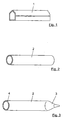
- Fig. 1 shows a hollow profile component 1, which may be formed for example as a frame member of a motor vehicle.
- the hollow profile component 1 may be a lateral roof frame of the motor vehicle.
- the hollow profile component 1 is preferably made of an aluminum material, but other materials may be suitable for the same.
- the hollow profile component 1 should consist of a formable material which has been produced, for example, by extrusion, roll forming, tube drawing or the like.
- the hollow profile component 1 has an outer flange portion 1a, which, however, plays no role in the method described below.
- the hollow profile component 1 can have approximately any desired external shape.
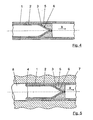
- the closure element 5 may optionally have a slightly larger diameter than the inner diameter of the hollow profile component 1, so that the reinforcing member 2 and the closure member 5 must be inserted with a certain force in the hollow profile component 1 and a certain material removal on the closure element 5 can take place ,
- FIG Fig. 5 A further method step, with which the hollow profile component 1 is shaped together with the reinforcing component 2 by means of internal high pressure, is in FIG Fig. 5 shown.
- the hollow profile component 1 is inserted with the reinforcing member 2 inserted in the same and the closure element 5 in a forming tool 7, which may be of known type.
- a pressure medium is introduced.
- the narrowed end 3 of the reinforcing member 2 is formed tapered and, as already mentioned above, adapted to the recess 6 in the closure element 5.
- the angle at which the narrowed end 3 is narrowed and which has an influence on the introduction of force via the closure element 5, also depends on the material of the hollow profile component 1, the reinforcing member 2 and in particular the closure element 5 as well as the clearance between the closure element 5 and the Hollow profile component 1 from.
Description
Die Erfindung betrifft ein Verfahren zur Umformung eines Hohlprofilbauteils mittels Innenhochdruck nach der im Oberbegriff von Anspruch 1 näher definierten Art (siehe z.B.
In der
Aus dem allgemeinen Stand der Technik sind verschiedene Verfahren zur Umformung von Doppelrohren mittels Innenhochdruck bekannt. Bei sämtlichen bislang bekannten Verfahren besteht die Grundvoraussetzung, dass das innere der beiden Rohre an seinen beiden Enden abgedichtet wird, wenn es mit seiner Außenwand an die Innenwand des äußeren Rohres angelegt werden soll, um mit demselben formschlüssig verbunden zu werden. Hierzu muss das innere Rohr jedoch an den Enden frei zugänglich sein, wodurch es erforderlich ist, dass das innere Rohr mindestens so lang wie das äußere Rohr ist. Insbesondere im Kraftfahrzeugbau wird es aus Gründen der Gewichtsverringerung aber immer häufiger zu der Notwendigkeit kommen, dass einzelne Hohlprofilbauteile nicht über ihre gesamte Länge verstärkt werden sollen, sondern dass die Verstärkungen nur über einen Teilbereich verlaufen sollen, was mit den bislang bekannten Verfahren nicht möglich ist, da das innere Rohr, wie oben beschrieben, stets mindestens so lang sein muss wie das äußere Rohr.Various methods for forming double pipes by means of internal high pressure are known from the general state of the art. In all the previously known methods, the basic requirement is that the inner of the two tubes is sealed at its two ends, if it is to be applied with its outer wall to the inner wall of the outer tube to be positively connected to the same. For this, however, the inner tube must be freely accessible at the ends, whereby it is necessary that the inner tube is at least as long as the outer tube. In particular, in the automotive industry, but it will increasingly come to the sake of weight reduction to the necessity that individual hollow profile components should not be reinforced over its entire length, but that the reinforcements should extend over only a portion, which is not possible with the previously known methods, since the inner tube, as described above, must always be at least as long as the outer tube.
Es ist daher Aufgabe der vorliegenden Erfindung, ein Verfahren zur Umformung eines Hohlprofilbauteils mittels Innenhochdruck zu schaffen, bei dem eine Verstärkung des Hohlprofilbauteils nur über einen Teil seiner Länge möglich ist.It is therefore an object of the present invention to provide a method for forming a hollow profile component by means of internal high pressure, in which a reinforcement of the hollow profile component is possible only over part of its length.
Erfindungsgemäß wird diese Aufgabe durch die in Anspruch 1 genannten Merkmale gelöst.According to the invention, this object is achieved by the features mentioned in
Durch das Verengen des Verstärkungsbauteils an einem Ende und das Aufbringen des Verschlusselements auf diesem verengten Ende ist es vorteilhafterweise nicht mehr erforderlich, das Verstärkungsbauteil an beiden Enden bis zu dem Ende des Hohlprofilbauteils zu führen. Vielmehr wird durch das verengte Ende des Verstärkungsbauteils und das daran angebrachte Verschlusselement beim Aufbringen des Drucks auf das Verstärkungsbauteil über das Verschlusselement eine Normalkraft auf die Innenseite des Hohlprofilbauteils aufgebracht, was zu einer Klemmwirkung führt, die die Lage des Verstärkungsbauteils und des Verschlusselements sichert und einen Formschluss zwischen den beteiligten Bauteilen herstellt.By the narrowing of the reinforcing member at one end and the application of the closure element on this narrowed end, it is advantageously no longer necessary to guide the reinforcing member at both ends to the end of the hollow profile component. Rather, by the narrowed end of the reinforcing member and the attached closure member during application of the Pressure on the reinforcing member via the closure element applied a normal force on the inside of the hollow profile component, resulting in a clamping action that secures the position of the reinforcing member and the closure member and produces a positive connection between the components involved.
Durch das erfindungsgemäße Verfahren ist es somit möglich, komplexe Hohlprofilbauteile mit lokalen, innenliegenden Verstärkungen zu versehen.The inventive method, it is thus possible to provide complex hollow profile components with local, internal reinforcements.
Das Aufbringen des Drucks auf das Verstärkungsbauteil kann in einer vorteilhaften Weiterbildung der Erfindung dadurch stattfinden, dass das offene Ende des Verstärkungsbauteils mit einem Dichtstempel verschlossen wird, und dass in das offene Ende des Verstärkungsbauteils ein Druckmedium eingeleitet wird.The application of pressure to the reinforcing member may take place in an advantageous development of the invention in that the open end of the reinforcing member is sealed with a sealing die, and that in the open end of the reinforcing member, a pressure medium is introduced.
Um ein Abgleiten des Verschlusselements von dem verengten Ende des Verstärkungselements beim Aufbringen des Drucks zu verhindern, kann in einer weiteren vorteilhaften Ausgestaltung der Erfindung vorgesehen sein, dass das verengte Ende des Verstärkungsbauteils spitz zulaufend und an eine Ausnehmung in dem Verschlusselement zumindest annähernd angepasst ausgeformt wird.In order to prevent slipping of the closure element from the narrowed end of the reinforcing element during application of the pressure, it can be provided in a further advantageous embodiment of the invention that the narrowed end of the reinforcing member is tapered and formed at least approximately adapted to a recess in the closure element.
Des weiteren kann vorgesehen sein, dass das Verengen des Endes des Verstärkungsbauteils so durchgeführt wird, dass das verengte Ende verschlossen wird. Auf diese Art und Weise wird unabhängig von der Ausgestaltung des Verschlusselements eine Dichtheit des Verstärkungsbauteils erreicht.Furthermore, it can be provided that the narrowing of the end of the reinforcing member is performed so that the narrowed end is closed. In this way, a tightness of the reinforcing member is achieved regardless of the design of the closure element.
Weitere vorteilhafte Ausgestaltungen und Weiterbildungen der Erfindung ergeben sich aus den restlichen Unteransprüchen. Nachfolgend ist ein Ausführungsbeispiel der Erfindung anhand der Zeichnung prinzipmäßig dargestellt.Further advantageous embodiments and modifications of the invention will become apparent from the remaining dependent claims. Hereinafter, an embodiment of the invention with reference to the drawing is shown in principle.
Es zeigt:
- Fig. 1
- ein Hohlprofilbauteil, das bei dem erfindungsgemäßen Verfahren einge- setzt wird;
- Fig. 2
- ein bei dem erfindungsgemäßen Verfahren eingesetztes Verstärkungsbau- teil in seinem Rohzustand;
- Fig. 3
- das Verstärkungsbauteil aus
Fig. 2 in einem bearbeiteten Zustand; - Fig. 4
- einen Schritt des erfindungsgemäßen Verfahrens; und
- Fig. 5
- einen weiteren Schritt des erfindungsgemäßen Verfahrens.
- Fig. 1
- a hollow profile component which is used in the method according to the invention;
- Fig. 2
- a reinforcing component used in the method according to the invention in its raw state;
- Fig. 3
- the reinforcing member from
Fig. 2 in a processed state; - Fig. 4
- a step of the method according to the invention; and
- Fig. 5
- a further step of the method according to the invention.
Das Hohlprofilbauteil 1 soll mittels eines in
In
Anschließend wird, wie in
Um das Einführen des Verstärkungsbauteils 2 in das Hohlprofilbauteil 1 zu erleichtern, den Aufwand für das nachfolgende Umformen zwischen den beiden Bauteilen 1 und 2 jedoch so weit wie möglich zu verringern, sollte der Außendurchmesser des Verstärkungsbauteils 2 geringfügig kleiner als der Innendurchmesser des Hohlprofilbauteils 1 sein.In order to facilitate the insertion of the reinforcing
Ein weiterer Verfahrensschritt, mit dem das Hohlprofilbauteil 1 zusammen mit dem Verstärkungsbauteil 2 mittels Innenhochdruck umgeformt wird, ist in
Da in der mit "X" bezeichneten Axialrichtung keine Wirkfläche mehr vorhanden ist, wird bei dieser Innenhochdruckumformung zum Einen die wirksame Kraft auf das verengte Ende 3 des Verstärkungsbauteils 2 reduziert, und zum Anderen bewirkt der Innendruck über das Verstärkungsbauteil 2 eine Normalkraft auf das Verschlusselement 5, was zu einer die Lage des Verschlusselements 5 sichernden Klemmwirkung führt und somit einen Formschluss zwischen dem Verstärkungsbauteil 2 und dem Verschlusselement 5 einerseits und dem Hohlprofilbauteil 1 andererseits entstehen lässt. Das Verschlusselement 5 wird üblicherweise auch zu einem gewissen Grad in das Hohlprofilbauteil 1 eingeprägt und damit zwischen den beiden Bauteilen 1 und 2 verkeilt.Since in the axial direction denoted by "X" no effective surface is no longer present, in this hydroforming on the one hand reduces the effective force on the narrowed
Um eine möglichst geringe Kraftkomponente in Axialrichtung des Hohlprofilbauteils 1 und des Verstärkungsbauteils 2 zu erhalten, ist das verengte Ende 3 des Verstärkungsbauteils 2 spitz zulaufend ausgebildet und, wie bereits oben erwähnt, an die Ausnehmung 6 in dem Verschlusselement 5 angepasst. Der Winkel, unter welchem das verengte Ende 3 verengt wird und welcher Einfluss auf die Krafteinleitung über das Verschlusselement 5 hat, hängt auch von dem Material des Hohlprofilbauteils 1, des Verstärkungsbauteils 2 und insbesondere des Verschlusselements 5 sowie von dem Spiel zwischen dem Verschlusselement 5 und dem Hohlprofilbauteil 1 ab.In order to obtain the smallest possible force component in the axial direction of the
Falls erforderlich, kann auf das Verstärkungsbauteil 2 auch von seinem verengten Ende 3 her mittels eines weiteren, nicht dargestellten Dichtstempels und mittels des Einleitens eines Druckmediums Druck aufgebracht werden. Auf diese Weise kann auch der nicht verstärkte Bereich des Hohlprofilbauteils 1 einer Umformung unterzogen und in die Form des Umformwerkzeugs 7 expandiert werden. Dabei sollte der Druckaufbau dem Druckaufbau an dem offenen Ende 4 nacheilen und derart eingestellt sein, dass das Verschlusselement 5 stets eine Dichtigkeit zwischen dem Verstärkungsbauteil 2 und dem Hohlprofilbauteil 1 gewährleistet. In diesem Fall wird vorzugsweise an dem verengten Ende 3 ein geringerer Druck als an dem offenen Ende 4 gewählt.If necessary, can on the reinforcing
Vor dem Aufbringen von Druck auf das Verstärkungsbauteil 2 in dem Umformwerkzeug 7 können an dem Hohlprofilbauteil 1 und an dem in das Hohlprofilbauteil 1 eingebrachten Verstärkungsbauteil 2 Biege- und/oder Prägeoperationen durchgeführt werden, um die äußere Form des Hohlprofilbauteils 1 zu verändern und/oder um die Lage des Verstärkungsbauteils 2 sowie des Verschlusselements 5 innerhalb des Hohlprofilbauteils 1 zu sichern. Falls erforderlich, kann auch ein Hinterschnitt zwischen den beiden Bauteilen 1 und 2 erzeugt werden.Before applying pressure to the reinforcing
Claims (12)
- Method for reshaping a hollow profile component by means of high internal pressure, a reinforcing component constructed as a hollow profile being inserted in the hollow profile component prior to reshaping, characterised in that the reinforcing component (2) is narrowed at an end (3) which is located inside the hollow profile component (1) during reshaping, and in that a closure element (5) is installed on the narrowed end (3) of the reinforcing component (2), a pressure being applied to the reinforcing component (2) in its state of insertion in the hollow profile component (1) from the open end (4) which is remote from the narrowed end (3), which pressure is such that the reinforcing component (2) and the closure element (5) are connected to the hollow profile component (1).
- Method according to claim 1, characterised in that in order to apply pressure to the reinforcing component (2), the open end (4) thereof is closed using a sealing ram (8), and in that a pressure medium is introduced into the open end (4) of the reinforcing component (2).
- Method according to either claim 1 or claim 2, characterised in that the narrowed end (3) of the reinforcing component (2) is formed such that it tapers to a point and is approximately adapted to a recess (6) in the closure element (5).
- Method according to any of claims 1, 2 or 3, characterised in that the narrowing of the end (3) of the reinforcing component (2) is carried out by swaging.
- Method according to any of claims 1 to 4, characterised in that the narrowing of the reinforcing component (2) is carried out in such a way that the narrowed end (3) is closed.
- Method according to any of claims 1 to 5, characterised in that pressure is applied to the reinforcing component (2) from its narrowed end (3) by means of a pressure ram (8) and by means of introducing a pressure medium.
- Method according to any of claims 1 to 6, characterised in that the reinforcing component (2) projects, at its open end (4), out of the hollow profile component (1).
- Method according to any of claims 1 to 7, characterised in that prior to applying pressure to the reinforcing component (2), bending and/or stamping operations are carried out on the hollow profile component (1) and on the reinforcing component (2) inserted in the hollow profile component (1).
- Method according to any of claims 1 to 8, characterised in that the outer diameter of the reinforcing component (2) is slightly smaller than the inner diameter of the hollow profile component (1).
- Method according to any of claims 1 to 9, characterised in that the material of the reinforcing component (2) has a greater strength than the material of the hollow profile component (1).
- Method according to any of claims 1 to 10, characterised in that the closure element (5) consists of metal.
- Method according to any of claims 1 to 10, characterised in that the closure element (5) consists of plastics material.
Applications Claiming Priority (1)
| Application Number | Priority Date | Filing Date | Title |
|---|---|---|---|
| DE200810012008 DE102008012008B3 (en) | 2008-03-01 | 2008-03-01 | Method for forming a hollow profile component by means of internal high pressure |
Publications (3)
| Publication Number | Publication Date |
|---|---|
| EP2095890A2 EP2095890A2 (en) | 2009-09-02 |
| EP2095890A3 EP2095890A3 (en) | 2012-01-18 |
| EP2095890B1 true EP2095890B1 (en) | 2013-04-17 |
Family
ID=40834392
Family Applications (1)
| Application Number | Title | Priority Date | Filing Date |
|---|---|---|---|
| EP20090002084 Expired - Fee Related EP2095890B1 (en) | 2008-03-01 | 2009-02-14 | Method for shaping a hollow profile component with high internal pressure |
Country Status (2)
| Country | Link |
|---|---|
| EP (1) | EP2095890B1 (en) |
| DE (1) | DE102008012008B3 (en) |
Families Citing this family (1)
| Publication number | Priority date | Publication date | Assignee | Title |
|---|---|---|---|---|
| CN104785604B (en) * | 2015-04-14 | 2016-10-19 | 桂林电子科技大学 | Metal thin-wall bimetallic tube impact hydraulic expansion method and device |
Family Cites Families (6)
| Publication number | Priority date | Publication date | Assignee | Title |
|---|---|---|---|---|
| JPS5838618A (en) * | 1981-09-01 | 1983-03-07 | Kawasaki Heavy Ind Ltd | Manufacture of double pipe having reinforced inner pipe end |
| DE19511970C2 (en) * | 1995-04-18 | 1998-07-09 | Werdau Fahrzeugwerk | Process for producing deformed multi-walled tubes with cavities between the walls |
| DE10013428C1 (en) * | 2000-03-17 | 2001-01-18 | Daimler Chrysler Ag | Double-walled hollow profile manufacturing method e.g. for i.c. engine exhaust gas line, has intermediate layer providing gap between inner and outer hollow profiles removed via opening in profle wall |
| CN1222378C (en) * | 2001-05-22 | 2005-10-12 | 三菱自动车工业株式会社 | Hydroforming method and product made by method |
| US7275521B2 (en) * | 2004-06-17 | 2007-10-02 | Usui Kokusai Sangyo Kaisha Limited | Joint structure of diverging branch pipe in fuel rail for internal combustion engine, diverging branch pipe and manufacture method of its diverging branch pipe |
| US7181846B2 (en) * | 2004-07-08 | 2007-02-27 | Torque-Traction Technologies, Inc. | Method of manufacturing a combined driveshaft tube and yoke assembly |
-
2008
- 2008-03-01 DE DE200810012008 patent/DE102008012008B3/en not_active Expired - Fee Related
-
2009
- 2009-02-14 EP EP20090002084 patent/EP2095890B1/en not_active Expired - Fee Related
Also Published As
| Publication number | Publication date |
|---|---|
| DE102008012008B3 (en) | 2009-09-03 |
| EP2095890A3 (en) | 2012-01-18 |
| EP2095890A2 (en) | 2009-09-02 |
Similar Documents
| Publication | Publication Date | Title |
|---|---|---|
| DE60101789T2 (en) | METHOD FOR PRODUCING A TUBULAR COMPONENT | |
| EP1989011B1 (en) | Method of producing a steering gear shaft part and stearing gear shaft having such a steering gear shaft part | |
| DE102006025522B4 (en) | Method and device for producing structured, closed hollow profiles | |
| DE102009038316A1 (en) | Method for producing a steering spindle part forming a section of a steering spindle | |
| DE102011080266A1 (en) | Method for positive connection of two pipe sections, involves connecting or joining electrically conductive pipe sections by electromagnetic pulse process in contactless form-fit or friction-fit manner | |
| DE102007038713B4 (en) | Process for the production of partially reinforced hollow profiles | |
| DE3328913A1 (en) | Device for fastening a pipe in a bore | |
| EP2095890B1 (en) | Method for shaping a hollow profile component with high internal pressure | |
| DE102007046788B3 (en) | Method for producing a locking ring bolt and locking bolt | |
| DE602005004598T2 (en) | Tube for hydroforming and method for hydroforming a tube | |
| DE19757946C2 (en) | pipe connection | |
| DE10019384B4 (en) | Method for producing a composite pipe and a composite pipe for transporting fluid media | |
| EP3812121B1 (en) | Vehicle door and production of the same | |
| DE102006012625C5 (en) | Method for producing profiles | |
| DE102006040072A1 (en) | Automobile hollow profile comprises a protective cover, which is formed by an internal high-pressure re-shaped component and which completely surrounds the hollow profile against mechanical surface damage | |
| EP1357017B1 (en) | Vehicle spaceframe | |
| EP2706276B1 (en) | Tube with reinforced inner wall and method for its manufacture | |
| DE102010014537B4 (en) | Structural component for a motor vehicle and method for its production | |
| DE19837131C2 (en) | Process for hydroforming two or more hollow bodies, each with at least one opening, in particular metal pipes or hollow metal profiles, and hydroforming machine for carrying out the process | |
| DE102004060218B4 (en) | Method for producing reinforced tubular elements | |
| EP2205370B1 (en) | Process and apparatus for producing a hollow body, and hollow body | |
| EP3546812A1 (en) | Hydraulic component system with an at least partially generative manufactured hydraulic component | |
| DE19901425A1 (en) | Rack-and-pinion steering mechanism for vehicle can be manufactured using low-grade material using tubular rack, with central cavity made in two different diameters linked by conical section | |
| DE102006031503B4 (en) | Method and device for bending hollow sections with minimal bending radius | |
| DE102015014503A1 (en) | Collapsible hollow tube for torque transmission in a cardan shaft and method for its production |
Legal Events
| Date | Code | Title | Description |
|---|---|---|---|
| PUAI | Public reference made under article 153(3) epc to a published international application that has entered the european phase |
Free format text: ORIGINAL CODE: 0009012 |
|
| AK | Designated contracting states |
Kind code of ref document: A2 Designated state(s): AT BE BG CH CY CZ DE DK EE ES FI FR GB GR HR HU IE IS IT LI LT LU LV MC MK MT NL NO PL PT RO SE SI SK TR |
|
| AX | Request for extension of the european patent |
Extension state: AL BA RS |
|
| PUAL | Search report despatched |
Free format text: ORIGINAL CODE: 0009013 |
|
| AK | Designated contracting states |
Kind code of ref document: A3 Designated state(s): AT BE BG CH CY CZ DE DK EE ES FI FR GB GR HR HU IE IS IT LI LT LU LV MC MK MT NL NO PL PT RO SE SI SK TR |
|
| AX | Request for extension of the european patent |
Extension state: AL BA RS |
|
| RIC1 | Information provided on ipc code assigned before grant |
Ipc: B21D 39/04 20060101ALI20111215BHEP Ipc: B21D 26/02 20110101AFI20111215BHEP |
|
| 17P | Request for examination filed |
Effective date: 20120718 |
|
| AKX | Designation fees paid |
Designated state(s): DE FR IT SE |
|
| GRAP | Despatch of communication of intention to grant a patent |
Free format text: ORIGINAL CODE: EPIDOSNIGR1 |
|
| RIC1 | Information provided on ipc code assigned before grant |
Ipc: B21D 26/02 20110101AFI20120823BHEP Ipc: B21D 39/04 20060101ALI20120823BHEP |
|
| GRAS | Grant fee paid |
Free format text: ORIGINAL CODE: EPIDOSNIGR3 |
|
| GRAA | (expected) grant |
Free format text: ORIGINAL CODE: 0009210 |
|
| AK | Designated contracting states |
Kind code of ref document: B1 Designated state(s): DE FR IT SE |
|
| REG | Reference to a national code |
Ref country code: SE Ref legal event code: TRGR |
|
| REG | Reference to a national code |
Ref country code: DE Ref legal event code: R096 Ref document number: 502009006851 Country of ref document: DE Effective date: 20130613 |
|
| PLBE | No opposition filed within time limit |
Free format text: ORIGINAL CODE: 0009261 |
|
| STAA | Information on the status of an ep patent application or granted ep patent |
Free format text: STATUS: NO OPPOSITION FILED WITHIN TIME LIMIT |
|
| 26N | No opposition filed |
Effective date: 20140120 |
|
| REG | Reference to a national code |
Ref country code: DE Ref legal event code: R097 Ref document number: 502009006851 Country of ref document: DE Effective date: 20140120 |
|
| REG | Reference to a national code |
Ref country code: FR Ref legal event code: PLFP Year of fee payment: 8 |
|
| REG | Reference to a national code |
Ref country code: DE Ref legal event code: R084 Ref document number: 502009006851 Country of ref document: DE |
|
| REG | Reference to a national code |
Ref country code: FR Ref legal event code: PLFP Year of fee payment: 9 |
|
| REG | Reference to a national code |
Ref country code: FR Ref legal event code: PLFP Year of fee payment: 10 |
|
| PGFP | Annual fee paid to national office [announced via postgrant information from national office to epo] |
Ref country code: GB Payment date: 20190220 Year of fee payment: 11 |
|
| PGFP | Annual fee paid to national office [announced via postgrant information from national office to epo] |
Ref country code: FR Payment date: 20190224 Year of fee payment: 11 Ref country code: SE Payment date: 20190222 Year of fee payment: 11 |
|
| PGFP | Annual fee paid to national office [announced via postgrant information from national office to epo] |
Ref country code: DE Payment date: 20200229 Year of fee payment: 12 |
|
| REG | Reference to a national code |
Ref country code: SE Ref legal event code: EUG |
|
| PG25 | Lapsed in a contracting state [announced via postgrant information from national office to epo] |
Ref country code: SE Free format text: LAPSE BECAUSE OF NON-PAYMENT OF DUE FEES Effective date: 20200215 |
|
| PG25 | Lapsed in a contracting state [announced via postgrant information from national office to epo] |
Ref country code: FR Free format text: LAPSE BECAUSE OF NON-PAYMENT OF DUE FEES Effective date: 20200302 |
|
| REG | Reference to a national code |
Ref country code: DE Ref legal event code: R119 Ref document number: 502009006851 Country of ref document: DE |
|
| PG25 | Lapsed in a contracting state [announced via postgrant information from national office to epo] |
Ref country code: IT Free format text: LAPSE BECAUSE OF NON-PAYMENT OF DUE FEES Effective date: 20200214 |
|
| PG25 | Lapsed in a contracting state [announced via postgrant information from national office to epo] |
Ref country code: DE Free format text: LAPSE BECAUSE OF NON-PAYMENT OF DUE FEES Effective date: 20210901 |