EP2095749A1 - Getränkemaschine mit Wassertank - Google Patents
Getränkemaschine mit Wassertank Download PDFInfo
- Publication number
- EP2095749A1 EP2095749A1 EP08405061A EP08405061A EP2095749A1 EP 2095749 A1 EP2095749 A1 EP 2095749A1 EP 08405061 A EP08405061 A EP 08405061A EP 08405061 A EP08405061 A EP 08405061A EP 2095749 A1 EP2095749 A1 EP 2095749A1
- Authority
- EP
- European Patent Office
- Prior art keywords
- water
- tank
- water tank
- beverage machine
- nozzle
- Prior art date
- Legal status (The legal status is an assumption and is not a legal conclusion. Google has not performed a legal analysis and makes no representation as to the accuracy of the status listed.)
- Withdrawn
Links
Images


Classifications
-
- A—HUMAN NECESSITIES
- A47—FURNITURE; DOMESTIC ARTICLES OR APPLIANCES; COFFEE MILLS; SPICE MILLS; SUCTION CLEANERS IN GENERAL
- A47J—KITCHEN EQUIPMENT; COFFEE MILLS; SPICE MILLS; APPARATUS FOR MAKING BEVERAGES
- A47J31/00—Apparatus for making beverages
- A47J31/44—Parts or details or accessories of beverage-making apparatus
- A47J31/60—Cleaning devices
- A47J31/605—Water filters
Definitions
- the present invention relates to a beverage machine with a water tank and a water filter.
- the beverage machine can be for example a coffee machine.
- a water filter cartridge is put in a water tank of a beverage machine to treat the raw water in the water tank.
- Granular filter material is located inside of the water filter cartridge to soften water flowing through the filter cartridge. Furthermore therewith small particles can be filtered out.
- the beverage machine can comprise a suction pump.
- a filter cartridge which comprises filtering means, an upflow chamber and a downflow chamber which communicate with one another in the upper region. Furthermore, the filter cartridge comprises an inlet opening and an inlet region arranged upstream of the inlet opening and an outlet opening which are both arranged in the bottom region. The outlet opening is connected to the inlet region via a bypass arranged in a lower portion of the upflow chamber and/or the downflow chamber or underneath the upflow and/or downflow chamber.
- An object of the invention is to provide a beverage machine, by which the water quality is constantly and durably improved.
- the hardness of the water is reduced and the pH-value stays unchanged.
- a further advantage is that the improvement of the water quality becomes predictable and that the water quality becomes nearly constant over a long time.
- the object is achieved by a beverage machine with a water tank with the features of the independent claim 1.
- the beverage machine according to the invention comprises a water tank with a tank nozzle, which forms a first water outlet, and which is provided for connecting the water tank with a filter cartridge. Furthermore, the water tank comprises a water channel in the floor area, which forms a second water outlet.
- the water channel is calibrated. Therefore for example, the diameter and/or the length of the water channel are taken into account. With a calibrated water channel a leveling of the filtering characteristic can be achieved over time.
- the water channel is integrated in the tank nozzle. This has the advantage, that no further valve or sealing element is necessary to avoid leakage when the water tank is removed from the beverage machine.
- the water channel is arranged in the floor of the water tank of the beverage machine according to the invention.
- the tank nozzle is welded or glued on the floor of the water tank of the beverage machine according to the invention.
- the water channel comprises a hole in the tank nozzle and a channel section, which extends between the tank nozzle and the floor of the water tank.
- the channel section is connected with the hole.
- the water channel is arranged in the floor of the water tank.
- the tank nozzle can comprise a collar, whereby the water channel is arranged below the collar.
- the beverage machine according to the invention can comprise a valve, which is provided at the outlet of the water tank. This has the advantage, that the water tank can be removed from the beverage machine but no water leaks out.
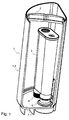
- FIG. 1 an embodiment of a water tank 1 with a filter cartridge 3 is depicted.
- a bow 2 is arranged so that one can bear the water tank 1. In particular, this is helpful when the water tank 1 is removed from the beverage machine.
- a tank nozzle 5 which is part of the water tank 1, is arranged for receiving a water filter cartridge 3.
- the water tank 1 is shown with the tank nozzle 5 but without the filter cartridge 3.
- the tank nozzle 5 comprises a circular collar 8 and a flange 15.
- the flange 15 of the tank nozzle 5 comprises four grooves 7.
- the floor 1.1 of the water tank 1 is provided with corresponding elevations, which are not shown in the figures.
- the tank nozzle 5 can be glued, bonded or welded on the floor 1.1 of the water tank 1.
- the tank nozzle 5 comprises a further groove 6, which forms a channel when the tank nozzle 5 is fixed on the floor 1.1 of the water tank 1.
- This water channel forms a bypass and connects the interior of the water tank 1 with the water outlet of the water tank.
- the diameter of the water channel is calibrated to provide a leveling of the filtering characteristics over time. It is in general less than 2 mm and depends among other things on the length and form of the water channel.
- the diameter of the collar 8 is matched to the diameter of the outlet 14 of the water filter cartridge 3.
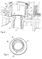
- FIG. 4 shows a second embodiment of the water tank 1 with a tank nozzle 50 and the filter cartridge 3, whereby the collar 58 of the tank nozzle 50 and the filter cartridge 3 remain unchanged.
- the tank nozzle 50 comprises a vertical hole 56 in the flange 51.
- the second embodiment of the tank nozzle 50 is shown in FIG. 5 a three dimensional view.
- the floor 1.1 of the water tank 1 comprises in the outlet area a circular recess 59 forming a channel section.
- the diameter of the recess 59 is smaller than the outer diameter of the flange 51.
- the hole 56 stays in conjunction with the recess 59.
- the hole 56 and the recess 59 form a water channel or bypass, which connects the interior of the water tank 1 with the external tank outlet 10 of the water tank 1.
- the recess 59 can also be integrated in the flange 51 of the tank nozzle 50. This is not shown in the figures.
- the external tank outlet 10 comprises a plunger 11 which is kept by means of a spring 12 in a closed position, when the water tank 1 is removed from the beverage machine. At the upper end of the plunger 11 a sealing 13 is provided. When the water tank 1 is fixed on the beverage machine, the plunger 11 is pressed upwards and the external outlet 10 is opened.
- the tank nozzle 50 comprises several grooves 57.
- the floor 1.1 of the water tank 1 is provided with corresponding elevations.
- the grooves 57 of the tank nozzle 50 are positioned over the elevations of the floor and form a tight fit between the floor 1.1 and the tank nozzle 50.
- the tank nozzle 50 can be glued, bonded or welded on the floor 1.1 of the water tank 1.
- the water tank 1 has two outlets 60 an 61.
- the first one is provided to receive the filter cartridge 3, and the second one is provided to form a water channel, with which raw water can be sucked out of the water tank without being filtered.
- the two outlets 60 and 61 lead to the same external tank outlet 10 of the water tank 1.
- FIG. 6 a third embodiment of the water tank 1 with a tank nozzle 100 and the filter cartridge 3 are depicted, whereby the filter cartridge 3 remains unchanged.
- the water tank 1 comprises a hole 106 in the floor 1.1, which is arranged beside the tank nozzle 100.
- the water tank 1 has also two outlets 60 and 106, but the hole 106, which forms the water channel, does not connect the interior of the water tank 1 with the external outlet 10, but the interior of the water tank 1 with the outside of the water tank in parallel to the external outlet 10.
- the external outlet 10 and the hole 106 can be connected beyond the water tank 1 (this is not shown in the figures 6 and 7 ).
- FIG. 7 the third embodiment of the water tank 1 is shown from another perspective.
Priority Applications (1)
| Application Number | Priority Date | Filing Date | Title |
|---|---|---|---|
| EP08405061A EP2095749A1 (de) | 2008-02-28 | 2008-02-28 | Getränkemaschine mit Wassertank |
Applications Claiming Priority (1)
| Application Number | Priority Date | Filing Date | Title |
|---|---|---|---|
| EP08405061A EP2095749A1 (de) | 2008-02-28 | 2008-02-28 | Getränkemaschine mit Wassertank |
Publications (1)
| Publication Number | Publication Date |
|---|---|
| EP2095749A1 true EP2095749A1 (de) | 2009-09-02 |
Family
ID=39628975
Family Applications (1)
| Application Number | Title | Priority Date | Filing Date |
|---|---|---|---|
| EP08405061A Withdrawn EP2095749A1 (de) | 2008-02-28 | 2008-02-28 | Getränkemaschine mit Wassertank |
Country Status (1)
| Country | Link |
|---|---|
| EP (1) | EP2095749A1 (de) |
Cited By (4)
| Publication number | Priority date | Publication date | Assignee | Title |
|---|---|---|---|---|
| ITPD20100068A1 (it) * | 2010-03-05 | 2011-09-06 | Laica Spa | Dispositivo per la disabilitazione di organi selettori ad intercettazione di flusso per sistemi filtranti a percolazione e kit includente detto dispositivo |
| WO2014101938A1 (en) * | 2012-12-26 | 2014-07-03 | Arcelik Anonim Sirketi | A water heater receptacle having a fluid outlet device |
| EP2138078B2 (de) † | 2008-06-27 | 2015-01-07 | Aquis Wasser-Luft-Systeme GmbH Lindau, Zweigniederlassung Rebstein | Wassertank und damit verbindbares separat ausgebildetes Filterpatronen-Anschlusselement |
| US9510707B2 (en) | 2010-01-06 | 2016-12-06 | Nestec S.A. | Vibration proof water tank of a beverage machine |
Citations (4)
| Publication number | Priority date | Publication date | Assignee | Title |
|---|---|---|---|---|
| EP1340442A1 (de) * | 1997-07-04 | 2003-09-03 | Aquis Wasser-Luft-Systeme GmbH, Lindau | Wasserbehälter mit Filterpatrone |
| DE102004049876A1 (de) | 2004-10-13 | 2006-04-20 | Brita Gmbh | Filterkartusche |
| DE102006005780A1 (de) * | 2006-02-03 | 2007-08-16 | Wp Engineering Ltd. | Filterkartusche für eine Getränkemaschine |
| DE102007038027A1 (de) * | 2006-08-10 | 2008-02-21 | Aquis Wasser-Luftsysteme GmbH Lindau, Zweigniederlassung Rebstein | Tank |
-
2008
- 2008-02-28 EP EP08405061A patent/EP2095749A1/de not_active Withdrawn
Patent Citations (4)
| Publication number | Priority date | Publication date | Assignee | Title |
|---|---|---|---|---|
| EP1340442A1 (de) * | 1997-07-04 | 2003-09-03 | Aquis Wasser-Luft-Systeme GmbH, Lindau | Wasserbehälter mit Filterpatrone |
| DE102004049876A1 (de) | 2004-10-13 | 2006-04-20 | Brita Gmbh | Filterkartusche |
| DE102006005780A1 (de) * | 2006-02-03 | 2007-08-16 | Wp Engineering Ltd. | Filterkartusche für eine Getränkemaschine |
| DE102007038027A1 (de) * | 2006-08-10 | 2008-02-21 | Aquis Wasser-Luftsysteme GmbH Lindau, Zweigniederlassung Rebstein | Tank |
Cited By (7)
| Publication number | Priority date | Publication date | Assignee | Title |
|---|---|---|---|---|
| EP2138078B2 (de) † | 2008-06-27 | 2015-01-07 | Aquis Wasser-Luft-Systeme GmbH Lindau, Zweigniederlassung Rebstein | Wassertank und damit verbindbares separat ausgebildetes Filterpatronen-Anschlusselement |
| US9510707B2 (en) | 2010-01-06 | 2016-12-06 | Nestec S.A. | Vibration proof water tank of a beverage machine |
| ITPD20100068A1 (it) * | 2010-03-05 | 2011-09-06 | Laica Spa | Dispositivo per la disabilitazione di organi selettori ad intercettazione di flusso per sistemi filtranti a percolazione e kit includente detto dispositivo |
| WO2011107488A1 (en) | 2010-03-05 | 2011-09-09 | Laica S.P.A. | A device for disabling flow shut-off selector members for percolating filter systems and a kit including said device |
| WO2014101938A1 (en) * | 2012-12-26 | 2014-07-03 | Arcelik Anonim Sirketi | A water heater receptacle having a fluid outlet device |
| CN104994770A (zh) * | 2012-12-26 | 2015-10-21 | 阿塞里克股份有限公司 | 具有流体出口装置的水加热器容器 |
| CN104994770B (zh) * | 2012-12-26 | 2018-02-23 | 阿塞里克股份有限公司 | 具有流体出口装置的水加热器容器 |
Similar Documents
| Publication | Publication Date | Title |
|---|---|---|
| CN102734022B (zh) | 高压泵 | |
| US8931399B2 (en) | Brewing apparatus with a drainage valve | |
| EP2095749A1 (de) | Getränkemaschine mit Wassertank | |
| EP1657099B1 (de) | Kraftstofffördereinheit | |
| RU2351271C2 (ru) | Фильтрующий картридж | |
| JP4597355B2 (ja) | 自動車用の燃料供給モジュール | |
| US20100206793A1 (en) | Suction filter and fuel supply device | |
| RU2608514C1 (ru) | Фильтр и бачок для машины для приготовления горячих напитков | |
| CN1137742A (zh) | 制备浸出式热饮料的自动机器 | |
| WO2017073259A1 (ja) | リターンフィルタ | |
| US8083823B2 (en) | Air filtration device for liquid or semi-liquid product pump | |
| US20170119205A1 (en) | Water filter assembly with protective check valve screen | |
| CN105593510A (zh) | 高压泵 | |
| AU2009295913B2 (en) | Filter cartridge for a beverage machine and beverage machine with a filter cartridge | |
| KR20040028626A (ko) | 차량용 연료 공급 장치 | |
| CN104395596A (zh) | 燃料供应系统 | |
| KR101573017B1 (ko) | 상수 가압 펌프유닛 | |
| US6453883B2 (en) | Fuel supply module for an internal combustion engine of a motor vehicle | |
| KR101116601B1 (ko) | 연료펌프모듈용 인탱크필터 | |
| US7673560B2 (en) | Brewing apparatus for a coffee machine | |
| CN209959380U (zh) | 一种设有新型过滤组件的下置燃油泵 | |
| CN209090885U (zh) | 一种咖啡过滤杯 | |
| CN104188514B (zh) | 一种冲泡增压器 | |
| CN108952882A (zh) | 易于维护的机油过滤器 | |
| CN107923352A (zh) | 燃料过滤器及元件 |
Legal Events
| Date | Code | Title | Description |
|---|---|---|---|
| PUAI | Public reference made under article 153(3) epc to a published international application that has entered the european phase |
Free format text: ORIGINAL CODE: 0009012 |
|
| AK | Designated contracting states |
Kind code of ref document: A1 Designated state(s): AT BE BG CH CY CZ DE DK EE ES FI FR GB GR HR HU IE IS IT LI LT LU LV MC MT NL NO PL PT RO SE SI SK TR |
|
| AX | Request for extension of the european patent |
Extension state: AL BA MK RS |
|
| AKX | Designation fees paid | ||
| REG | Reference to a national code |
Ref country code: DE Ref legal event code: 8566 |
|
| STAA | Information on the status of an ep patent application or granted ep patent |
Free format text: STATUS: THE APPLICATION IS DEEMED TO BE WITHDRAWN |
|
| 18D | Application deemed to be withdrawn |
Effective date: 20100303 |