EP2095477B1 - Automatische funktion mit wählbarem sicherungswert für einzelsicherungen und sicherungstafeln - Google Patents
Automatische funktion mit wählbarem sicherungswert für einzelsicherungen und sicherungstafeln Download PDFInfo
- Publication number
- EP2095477B1 EP2095477B1 EP07852248.9A EP07852248A EP2095477B1 EP 2095477 B1 EP2095477 B1 EP 2095477B1 EP 07852248 A EP07852248 A EP 07852248A EP 2095477 B1 EP2095477 B1 EP 2095477B1
- Authority
- EP
- European Patent Office
- Prior art keywords
- fuse
- trip value
- load
- electronic
- shunt
- Prior art date
- Legal status (The legal status is an assumption and is not a legal conclusion. Google has not performed a legal analysis and makes no representation as to the accuracy of the status listed.)
- Not-in-force
Links
Images








Classifications
-
- H—ELECTRICITY
- H02—GENERATION; CONVERSION OR DISTRIBUTION OF ELECTRIC POWER
- H02H—EMERGENCY PROTECTIVE CIRCUIT ARRANGEMENTS
- H02H3/00—Emergency protective circuit arrangements for automatic disconnection directly responsive to an undesired change from normal electric working condition with or without subsequent reconnection ; integrated protection
- H02H3/08—Emergency protective circuit arrangements for automatic disconnection directly responsive to an undesired change from normal electric working condition with or without subsequent reconnection ; integrated protection responsive to excess current
-
- H—ELECTRICITY
- H02—GENERATION; CONVERSION OR DISTRIBUTION OF ELECTRIC POWER
- H02H—EMERGENCY PROTECTIVE CIRCUIT ARRANGEMENTS
- H02H3/00—Emergency protective circuit arrangements for automatic disconnection directly responsive to an undesired change from normal electric working condition with or without subsequent reconnection ; integrated protection
- H02H3/006—Calibration or setting of parameters
Definitions
- the technical field of this disclosure generally relates to providing fuse and fuse panels that are field programmable. Some embodiments of the field programmable fuses and fuse panels are based on electronic fuses.
- a fuse panel with a number of fuses are used.
- the trip value of each fuse is selected to protect each load device connected to the fuse.
- a free fuse with a proper trip value for the new load device is selected.
- Fuse panels of today are based on a number of different technologies such as melting wire types, heat activated types and electronic types. No matter the type, the fuse "trips" or breaks the circuit to the load device when the current provided to the load device exceeds the trip value.
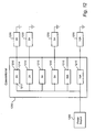
- FIG. 12 illustrates a conventional fuse panel 1200 that includes a plurality of individual fuses 1210.
- the first two fuses have the trip values set at 2 amperes (or 2A)
- the second 2 fuses have their trip value set at 5A
- the third set of fuses have their trip value set at 10A.
- Each fuse provides power from an external power source 1240 to the respective load devices 1250.
- the fuses 1210 can be electronic type fuses.
- FIG. 13 illustrates a conventional electronic fuse 1300.
- the conventional electronic fuse 1300 includes an electronic switch 1310 coupled to a shunt 1330 to deliver power from the external source connected at input 1212 (see also FIG. 12 ) to the load device connected at output 1214.
- the electronic fuse 1300 also includes a voltage comparator 1320 that measures a voltage drop across the shunt 1330. The voltage drop across the shunt 1330 is related to an amount of current flowing through the shunt 1330 to the load device 1250. If the voltage drop across the shunt 1330 is at or above a threshold level, the comparator 1320 outputs a signal to the electronic switch 1310 to turn off. By setting the threshold voltage, an appropriate trip value is set for the electronic fuse 1300.
- a major disadvantage with the conventional fuse and fuse panels is that the trip value of each fuse must be determined during the production of the panel and remains fixed. For electronic fuses such as those illustrated in FIG. 13 , threshold voltage is fixed during the production. This requires that each panel be tailored for a number of load devices at specific current values. This creates a problem when a new load device is desired to be added but there is no free fuse available with the correct trip values. Referring back to FIG. 12 , it is seen that both 2A fuses are already occupied. If another 2A load device is desired to be connected, it will impossible with the conventional fuse panel. This is despite the fact that there are fuses with other trip values available such as the 5A and 10A fuses.
- US 5440441 A discloses a NO-BLO-FUSE comprising a current sensing device used to generate a voltage drop proportional to the current flowing through the device. When the voltage drop reaches a predetermined level, resulting from an over-current condition, it trips a control means that opens a solid state switch in the line. After a defined delay interval the circuit will automatically reset to close the solid state switch. If the over-current condition still exists, the control means will again open the solid state switch. This cycle is repeated at the delay interval until the over-current condition has subsided. Circuits are also disclosed which provide over-voltage protection, through detectors which trigger the control means when an over-voltage condition is detected. The application to lightning or surge protection is also disclosed, for single line and multi-line environments. Furthermore, disclosed is a micro computer based power line protection, monitoring and management system that manages one or more source(s) and one or more user(s) of the power.
- EP 1536537 A2 discloses a fuse to disconnect safety devices such as signal lamps and switches.
- the fuse comprises a current sensor in the load line connected to a software-controlled controller that disconnects when excess current flows.
- the sensor also connects to a hardware fuse with adjustable threshold that generates a switch-off signal and there is a test simulation unit.
- US 5671115 A discloses that electronic driving components sized to drive contactors of a determined power class are generally used.
- the object is to create a process and circuitry which allows contactors of different power classes to be driven by a single driving component.
- the user selects on a scale the switching position corresponding to the contactor to be driven.
- a reference voltage proportional to the magnitude of the starting current of the respective contactor is thus selected.
- An automatic regulation keeps constant the starting current during the starting time of the contactor.
- a measurement voltage proportional to the magnitude of the starting system and dropping across a measuring resistor is supplied to a first input of a comparator, a reference voltage which may be selected by a coding switch being applied to the second input of the comparator.
- the output of the comparator co-operates with a switching element which switches the starting current.
- This circuitry may be mounted upstream of existing contactors, in particular on a top hat rail.
- a field programmable fuse as set out in Claim 1.
- Modifying the trip value - a value of current at which a fuse trips - for an electronic fuse may be done in several ways. These include bypassing parts of the shunt and bypassing parts of the signal that is connected to the comparator. Another way is to use programming pins as inputs to a programming controller to modify the trip value of the electronic fuse.
- FIGS. 1A and 1B illustrate example embodiments of field programmable fuses 100.
- the trip values of the programmable fuses 100 are not fixed upon production, but can be programmed in the field - that is, after production - many times over as the need arises.
- the field programmable fuses 100 can be tailored for AC only, for DC only, or for a combination of AC and DC systems.
- the field programmable fuse 100 includes an electronic fuse 110.
- the electronic fuse 110 is configured to provide power from an external source coupled to its power input 116 to a load device 130 that is coupled to its power output 112.
- the electronic fuse 110 also includes one or more field selectable trip value inputs 115 such that the trip value of the electronic fuse 110 is set based on the values applied to the field selectable trip value inputs 115.
- Inputs to the trip value inputs 115 may be provided directly.
- the programmable fuse 100 may also include a programming connector 120 with programming pins 135 connected to the trip value inputs 115.
- the program connector 120 can make the process of selecting the trip value easier and less error prone.
- the load device 130 may be connected directly to the electronic fuse 110 as illustrated in FIG. 1B or through the program connector 120 as illustrated in FIG. 1A .
- the number of trip value inputs 115 may be reduced as will be demonstrated later.
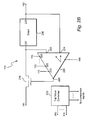
- FIG. 2A illustrates an example embodiment of the electronic fuse 110.
- the electronic fuse 110 includes an electronic switch 210 and a variable shunt 230 configured to deliver power from the external source coupled to the power input 116 to the load device 130 coupled to the power output 112.
- the electronic fuse 110 also includes a comparator 220 coupled to the variable shunt 230 and is configured to measure a voltage drop across the variable shunt 230. When the voltage drop across the variable shunt 230 is above or substantially at a pre-determined threshold, the voltage comparator 220 outputs a TURN OFF signal to the electronic switch 210, at which the electronic switch 210 switches off the delivery of the load current.
- variable shunt 230 (denoted by the angle sign) is configured to vary its impedance value based on the trip value settings provided at the trip value inputs 115.
- the impedance value of the variable shunt 230 By varying the impedance value of the variable shunt 230, the trip value of the electronic fuse 110 is also varied.
- the voltage drop across the variable shunt 230 is a product of the load current flowing through the variable shunt 230 and its impedance. If the impedance is lowered, the trip value is accordingly increased since the voltage drop across the variable shunt 230 is correspondingly lowered. Conversely, increasing the impedance of the variable shunt 230 decreases the trip value.
- FIGS. 3A and 3B illustrate example implementations of the variable shunt 230.
- the variable shunt 230 includes a plurality of shunt devices 310 and a plurality of bypass gates 320.
- the shunt devices 310 are operatively coupled to deliver the load current from the external source to the load device, and the bypass gates 320 are coupled to the plurality shunt devices 310 and provide a capability to selectively bypass one or more of the shunt devices 310. While only two shunt devices 310 are illustrated in both FIGS. 3A and 3B , it is to be noted that any number of shunt devices may be utilized. Similarly, the number of bypass gates 320 are not limited to the illustrated example implementations.
- the plurality of devices 310 are connected in series.
- the plurality of bypass gates 320 are provided. By selectively activating gates 235 of the bypass gates 320, an electrical pathway may be made to bypass either of shunt devices 310 1 or 310 2 .
- the load current from input 237 should pass through at least one of the shunt devices 310 1 and 310 2 .
- each shunt device 310 be different.
- the first shunt device 310 1 may have an impedance value of 1 ⁇ and the second shunt device 310 2 may have an impedance value of 2 ⁇ .
- the load current may be made to flow only through the first shunt device 310 1 by deactivating the first bypass gate 320 1 and activating second and third bypass gates 320 2 and 320 3 .
- the load current may be made to flow only through the second shunt device 310 2 by activating first and second bypass gates 320 1 and 320 2 and deactivating the third bypass gate 320 3 .
- the low current may be made to flow through both first and second shunt devices 310 1 and 310 2 by deactivating the first and third bypass gates 320 1 and 320 3 .
- the plurality of shunt devices 310 may also be coupled in parallel with each other as illustrated in FIG. 3B .
- the total impedance of the variable shunt 230 can be achieved by activating/ deactivating different combinations of the bypass gates 320 1 and 320 2 .
- FIGS. 3A and 3B illustrated series implementation and parallel implementation in isolation, having a combination of both fall within the scope of the disclosure. Also, having any number of shunt devices 310 and bypass gates 320 fall within the scope of the disclosure.
- the trip value inputs 115 may be provided directly to the inputs 235 of the variable shunts 230.
- the electronic fuse 110 may include a trip value controller 270 which takes as inputs the values set on the trip value inputs 115 and outputs control signals to the inputs 235 of the variable shunt 230.
- An advantage of the trip value controller 270 is that it can minimize the number of trip value inputs 115 that are required to interface with an external programming controller while providing a fine granularity of trip value settings within the electronic fuse 110.
- FIG. 3A shows three bypass gates 320 that can be individually activated to bypass either the first or the second shunt device 310 1 or 310 2 . If the gate inputs 235 of the bypass gate 320 are directly coupled to the trip value inputs 115, then three trip value inputs 115 will be required. However, referring back to FIG. 2A , if the inputs 235 are connected to the trip value controller 270, then only two trip value inputs 115 will be required assuming that the trip value inputs 115 take on a binary signal. This is because there are only three combinations possible in FIG. 3A . If the trip value input 115 can take on more than two electrical values - such as power, ground and some intermediate value - then the number of trip value input 115 can be reduced to one for both FIGS. 3A and 3B .
- the field programming capability may be provided by the variable comparator 220 as illustrated in FIG. 2B .
- the comparator 220 is variable in a sense that the threshold voltage at which the TURN OFF signal is provided is varied according to the trip value set based on the inputs provided to the trip value inputs 115. If it is desired to increase the trip value, the threshold voltage may be increased. If it is desired to decrease the trip value, then the threshold voltage may be decreased.
- the trip value inputs 115 may be provided directly to the variable comparator 220 via the comparator inputs 225 as shown in FIG. 2B , or may be provided through the trip value controller 270 as understood from the previous description.
- the comparator 220 outputs the TURN OFF signal based on the threshold voltage drop across the whole of the shunt 230.
- a variable voltage divider 240 may be provided as illustrated in FIG. 2C .
- the variable voltage divider 240 provides a divided voltage to the comparator 220.
- the voltage divider 240 outputs a portion of the voltage drop measured across the shunt 230 as the divided voltage.
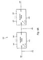
- FIGS. 4A and 4B illustrate example implementations of the voltage divider 240.
- the voltage divider 240 includes first and second impedance groups 410 and 420 connected in series.
- the first impedance group 410 has a first impedance value and the second impedance group 420 has a second impedance value. Both the first and second impedance values 410, 420 can be varied based on the trip value settings.
- the voltage drop across the first impedance group is output as the divided voltage
- FIG. 4B the voltage drop across the second impedance group 420 is output as the divided voltage.
- the impedance groups 410, 420 may be implemented as illustrated in FIGS. 5A and 5B .
- the impedance groups include a plurality of impedance devices 510 along with a plurality of bypass gates 520 connected to selectively bypass the impedance devices 510.
- the impedance devices 510 may be connected in series or in parallel with each other. It is also contemplated that various combinations of serial and parallel combinations are within the scope of the disclosure.
- the structure of the impedance groups 410, 420 are similar to the plurality of shunt devices 310 as illustrated in FIGS. 3A and 3B . Thus, detailed description of the operations of the impedance groups will be omitted.
- the trip value controller 270 may be optionally provided to control the operations of the impedance groups 410, 420.
- the programmable fuse 100 optionally includes the programming connector 120 coupled to the electronic fuse 110.
- the programming connector 120 includes a plurality of programming pins 135 that are field settable to take on one of a plurality of electrical values.
- the trip value of the electronic fuse 110 is determined by a combination of the electrical values set on the programming pins 135.
- the electrical values can be any one of open (i.e., not connected), ground, power, and one or more voltage values other than the ground and the power.
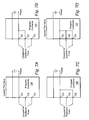
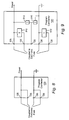
- FIGS. 6-9 illustrate various implementations of setting the electrical values to the programming pins 135.
- the programming pins 135 are set to take on one of two electrical values - connected to ground or open.
- Various combinations of the electrical values applied to the programming pins 135 determine the trip value setting.
- the programming pins may take on one of power or open.
- the programming pins may take on one of three values - open, connected to power and connected to ground.
- FIG. 9 illustrates that intermediate voltages may also be provided by providing impedance devices 910 connected to either the ground or the power. Combining the features of FIGs. 6A-6D , 7A-7D , 8 and 9 are within the scope of the disclosure.
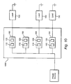
- FIG. 10 illustrates an embodiment of a fuse panel 1000.
- the fuse panel 1000 includes a plurality of programmable fuses 100. While not specifically shown, the fuse panel 1000 can also include one or more fixed fuses.
- the fuse panel 1000 is generic in that the trip values of the programmable fuses 100 are not fixedly set at the time of production. With this fuse panel, as long as there is a programmable fuse 100 available, another load device 130 may be added. Thus, the expense and difficulty associated with the conventional fuse panels are avoided.
- Each programmable fuse 100 can be individually programmed apart from other fuses. Also, a subset, that is two or more of the programmable fuses 100, less than the whole, can be simultaneously field programmable.
- the fuses 100 and the fuse panel 1000 can be implemented mechanically, for example, as a fuse panel connector implemented as an edge connector directly on a printed circuit board (PCB).
- FIG. 11 illustrates an embodiment of this concept.
- programming fingers 1130, 1140 are located on one side of the PCB 1160.
- a plug is implemented as a blade 1110 on each side. The width of the blade 1110 determines the amount of current that can be used.
- FIG. 11 three blades 1110 of varying widths are illustrated. In general, the wider the blade width, the higher current than can be used.
- the trip value programming is performed by the blade 1110 connecting to the one or more programming fingers 1130 and 1140 to a power or to ground.
- the programming finger 1130 is connected to the power 1120 (providing a signal to the "A" trip value input) while the programming finger 1140 is left unconnected (providing no signal to the "B" trip value input).
- both programming fingers are connected to power to provide signals to the "A" and "B" trip value inputs 115 of the electronic fuse 110.
- no programming finger are connected.
- the programming fingers 1130 and 1140 may be made to connect to a ground or some other voltage when a blade 1110 of proper width is connected depending on the application.
- the load select blade 1110 may be integrated into a single physical piece with a load input of the load device 130.
- the load select blade 1110 may be integrated into a single physical piece with the power output 112 of the programmable fuse 100.
- the electronic fuse 110 can optionally include a reset (R/ S) input 118 to provide a capability to reset the electronic fuse 110.
- R/ S reset
- the electronic fuse 110 switches off.
- the comparator 220 can output the TURN OFF signal to the electronic switch 210 in FIGs. 2A - 2C .
- the R/ S input 118 is activated under this type of a conditions, the electronic fuse 110 switches ON.
- the R/S input 118 may be used for safety as well. For example, when no load device is connected to the electronic fuse 110, the R/S input 118 may be used to cause the comparator 220 to output the TURN OFF signal to the electronic switch 210. In this way, no power is output when there is no load on the electronic fuse 210 promoting safety. When a mechanical implementation such as illustrated in FIG. 11 is considered, determining whether or not a load device is connected will be possible simply by determining whether or not the load select blade 1110 is absent or present.
- the R/S input 118 is not the only way to implement the safety feature. In general, it is sufficient to detect whether or not a load device 130 is connected and to prevent the power from reaching the power output 112 of the electronic fuse 110 when there is no load device 130 connected.
Landscapes
- Fuses (AREA)
- Charge And Discharge Circuits For Batteries Or The Like (AREA)
Claims (23)
- Feldprogrammierbare Sicherung (100), umfassend:eine elektronische Sicherung (110) zum Liefern eines Laststroms von einer externen Quelle über einen Leistungseingang (116) an ein Lastelement (130) über einen Leistungsausgang (112),wobei die elektronische Sicherung (110) umfasst:einen regelbaren Nebenschluss (230) zum Liefern des Laststroms von einer externen Quelle an das Lastelement (130);einen Komparator (220) zum Messen eines Spannungsabfalls am regelbaren Nebenschluss (230); undeinen elektronischen Schalter (210) zum Schalten der Lieferung des Laststroms von der externen Quelle an den regelbaren Nebenschluss (230) auf ON und OFF, wobei:der Spannungskomparator (220) so ausgelegt ist, dass er ein TURN OFF-Signal an den elektronischen Schalter (210) ausgibt, wenn der Spannungsabfall am regelbaren Nebenschluss (230) über oder im Wesentlichen bei einer vorbestimmten Schwelle ist,der elektronische Schalter (210) so ausgelegt ist, dass er die Lieferung des Laststroms auf OFF schaltet, wenn das TURN OFF-Signal vom Spanungskomparator (220) empfangen wird, undder regelbare Nebenschluss (230) so ausgelegt ist, dass er seinen Impedanzwert basierend auf dem für die elektronische Sicherung (210) festgelegten Auslösewert ändert,dadurch gekennzeichnet, dass:die elektronische Sicherung (110) einen oder mehrere feldselektierbare Auslösewerteingänge (115) umfasst, derart dass ein Auslösewert der elektronischen Sicherung (110) basierend auf Werten festgelegt wird, die an den einen oder die mehreren feldselektierbaren Auslösewerteingänge (115) angelegt werden, wobei die Auslösewerteingänge (115) physisch voneinander beabstandet sind, das Lastelement (130) ein Lastauswahlmesser (1110) umfasst, derart dass, wenn eingesetzt, einer oder mehrere der Auslösewerteingänge (115) mit dem Lastauswahlmesser (1110) in physischen Kontakt kommen, und der für die elektronische Sicherung (110) festgelegte Auslösewert auf einer Kombination der Auslösewerteingänge (115) basiert, die mit dem Lastauswahlmesser (1110) in Kontakt kommen; unddie elektronische Sicherung (110) so ausgelegt ist, dass sie aufhört, den Laststrom an das Lastelement (130) zu liefern; wenn eine Menge des an das Lastelement (130) gelieferten Laststroms den für die elektronische Sicherung (110) festgelegten Auslösewert überschreitet.
- Feldprogrammierbare Sicherung (100) nach Anspruch 1, ferner umfassend eine Auslösewertsteuerung (270) zum Steuern des Impedanzwerts des regelbaren Nebenschlusses (230) basierend Eingaben in die Auslösewerteingänge (115).
- Feldprogrammierbare Sicherung (100) nach Anspruch 1, wobei der regelbare Nebenschluss (230) umfasst:eine Mehrzahl von Nebenschlusselementen (310) zum Liefern des Laststroms von einer externen Quelle an das Lastelement (130); undeine Mehrzahl von Bypass-Gattern (320) zum Bereitstellen einer Fähigkeit zum selektiven Überbrücken eines oder mehrerer der Mehrzahl von Nebenschlusselementen (310), derart dass die Mehrzahl von Bypass-Gattern (320) so ausgelegt ist, dass sie verschiedene Kombinationen der Mehrzahl von Nebenschlusselementen (310) basierend auf verschiedenen Auslösewerteinstellungen überbrückt.
- Feldprogrammierbare Sicherung (100) nach Anspruch 3,
wobei mindestens ein Nebenschlusselement (310) derart konfiguriert ist, dass es zu mindestens einem anderen Nebenschlusselement (310) funktionell parallel gekoppelt ist, oder mindestens ein Nebenschlusselement (310) derart konfiguriert ist, dass es mit mindestens einem anderen Nebenschlusselement (310) funktionell in Reihe gekoppelt ist, oder beides. - Feldprogrammierbare Sicherung (100), umfassend:eine elektronische Sicherung (110) zum Liefern eines Laststroms von einer externen Quelle über einen Leistungseingang (116) an ein Lastelement (130) über einen Leistungsausgang (112),wobei die elektronische Sicherung (110) umfasst:einen Nebenschluss (230) zum Liefern des Laststroms von einer externen Quelle an das Lastelement (130);einen regelbaren Komparator (220) zum Messen eines Spannungsabfalls am Nebenschluss (230); undeinen elektronischen Schalter (210) zum Schalten der Lieferung des Laststroms von der externen Quelle an den Nebenschluss (230) auf ON und OFF, wobei:der regelbare Spannungskomparator (220) so ausgelegt ist, dass er ein TURN OFF-Signal an den elektronischen Schalter (210) ausgibt, wenn der Spannungsabfall am regelbaren Nebenschluss (230) über oder im Wesentlichen bei einer Schwellenspannung ist, und die Schwellenspannung basierend auf dem für die elektronische Sicherung (210) festgelegten Auslösewert ändert, undder elektronische Schalter (210) so ausgelegt ist, dass er die Lieferung des Laststroms auf OFF schaltet, wenn das TURN OFF-Signal vom regelbaren Spanungskomparator (220) empfangen wird,dadurch gekennzeichnet, dass:die elektronische Sicherung (110) einen oder mehrere feldselektierbare Auslösewerteingänge (115) umfasst, derart dass ein Auslösewert der elektronischen Sicherung (110) basierend auf Werten festgelegt wird, die an den einen oder die mehreren feldselektierbaren Auslösewerteingänge (115) angelegt werden, wobei die Auslösewerteingänge (115) physisch voneinander beabstandet sind, das Lastelement (130) ein Lastauswahlmesser (1110) umfasst, derart dass, wenn eingesetzt, einer oder mehrere der Auslösewerteingänge (115) mit dem Lastauswahlmesser (1110) in physischen Kontakt kommen, und der für die elektronische Sicherung (110) festgelegte Auslösewert auf einer Kombination der Auslösewerteingänge (115) basiert, die mit dem Lastauswahlmesser (1110) in Kontakt kommen; unddie elektronische Sicherung (110) so ausgelegt ist, dass sie aufhört, den Laststrom an das Lastelement (130) zu liefern, wenn eine Menge des an das Lastelement (130) gelieferten Laststroms den für die elektronische Sicherung (110) festgelegten Auslösewert überschreitet.
- Feldprogrammierbare Sicherung (100) nach Anspruch 5,
ferner umfassend eine Auslösewertsteuerung (270) zum Steuern der Schwellenspannung des regelbaren Komparators (220) basierend auf Eingaben in die Auslösewerteingänge (115). - Feldprogrammierbare Sicherung (100), umfassend:eine elektronische Sicherung (110) zum Liefern eines Laststroms von einer externen Quelle über einen Leistungseingang (116) an ein Lastelement (130) über einen Leistungsausgang (112), wobeidie elektronische Sicherung (110) einen oder mehrere feldselektierbare Auslösewerteingänge (115) umfasst, derart dass ein Auslösewert der elektronischen Sicherung (110) basierend auf Werten festgelegt wird, die an den einen oder die mehreren feldselektierbaren Auslösewerteingänge (115) angelegt werden, wobei die Auslösewerteingänge (115) physisch voneinander beabstandet sind, das Lastelement (130) ein Lastauswahlmesser (1110) umfasst, derart dass, wenn eingesetzt, einer oder mehrere der Auslösewerteingänge (115) mit dem Lastauswahlmesser (1110) in physischen Kontakt kommen, und der für die elektronische Sicherung (110) festgelegte Auslösewert auf einer Kombination der Auslösewerteingänge (115) basiert, die mit dem Lastauswahlmesser (1110) in Kontakt kommen; unddie elektronische Sicherung (110) so ausgelegt ist, dass sie aufhört, den Laststrom an das Lastelement (130) zu liefern, wenn eine Menge des an das Lastelement (130) gelieferten Laststroms den für die elektronische Sicherung (110) festgelegten Auslösewert überschreitet;wobei die elektronische Sicherung (110) umfasst:einen Nebenschluss (230) zum Liefern des Laststroms von einer externen Quelle an das Lastelement (130);einen regelbaren Spannungsteiler (240), der über den Nebenschluss gekoppelt ist, zum Ausgeben einer geteilten Spannung;einen Komparator (220) zum Messen der geteilten Spannung vom regelbaren Spannungsteiler (240); undeinen elektronischen Schalter (210) zum Schalten der Lieferung des Laststroms von der externen Quelle an den Nebenschluss (230) auf ON und OFF, wobei:der Spannungskomparator (220) so ausgelegt ist, dass er ein TURN OFF-Signal an den elektronischen Schalter (210) ausgibt, wenn die geteilte Spannung vom regelbaren Spannungsteiler (240) über oder im Wesentlichen bei einer vorbestimmten Schwelle ist,der elektronische Schalter (210) so ausgelegt ist, dass er die Lieferung des Laststroms auf OFF schaltet, wenn das TURN OFF-Signal vom Spanungskomparator (220) empfangen wird, undder regelbare Spannungsteiler (240) so ausgelegt ist, dass er einen variierenden Teil eines Spannungsabfalls am Nebenschluss (230) als die geteilte Spannung basierend auf dem für die elektronische Sicherung (210) festgelegten Auslösewert ausgibt.
- Feldprogrammierbare Sicherung (100) nach Anspruch 7,
ferner umfassend eine Auslösewertsteuerung (270) zum Steuern des Teils des Spannungsabfalls am Nebenschluss (230) als die geteilte Spannung basierend auf dem für die elektronische Sicherung (210) festgelegten Auslösewert. - Feldprogrammierbare Sicherung (100) nach Anspruch 7,
wobei der regelbare Spannungsteiler (240) umfasst:eine erste Impedanzgruppe (410), die einen ersten Impedanzwert aufweist und funktionell mit dem elektronischen Schalter (210) gekoppelt ist;eine zweite Impedanzgruppe (420), die einen zweiten Impedanzwert aufweist und mit der ersten Impedanzgruppe (410) funktionell in Reihe gekoppelt ist und außerdem mit dem Leistungsausgang (112) funktionell gekoppelt ist,
wobei:einer von einem Spannungsabfall an der ersten Impedanzgruppe (410) oder der zweiten Impedanzgruppe (420) so ausgelegt ist, dass er als die geteilte Spannung ausgegeben wird, undeine oder beide der ersten und zweiten Impedanzgruppen (410, 420) so ausgelegt sind, dass sie ihre Impedanzwerte basierend auf dem für die elektronische Sicherung (210) festgelegten Auslösewert ändern. - Feldprogrammierbare Sicherung (100) nach Anspruch 9,
wobei mindestens eine der ersten Impedanzgruppe (410) oder der zweiten Impedanzgruppe (420) umfasst:eine Mehrzahl von Impedanzelementen (510), die funktionell miteinander gekoppelt sind;eine Mehrzahl von Bypass-Gattern (510), die funktionell mit der Mehrzahl von Impedanzelementen (510) gekoppelt ist, um eine Fähigkeit zum selektiven Überbrücken eines oder mehrerer der Mehrzahl von Impedanzelementen (510) bereitzustellen, derart dass die Mehrzahl von Bypass-Gattern (520) so ausgelegt ist, dass sie verschiedene Kombinationen der Mehrzahl von Impedanzelementen (510) basierend auf verschiedenen Auslösewerteinstellungen überbrückt. - Feldprogrammierbare Sicherung (100) nach Anspruch 10,
wobei mindestens ein Impedanzelement (510) zu mindestens einem anderen Nebenschlusselement (510) funktionell parallel gekoppelt ist, oder mindestens ein Impedanzelement (510) mit mindestens einem anderen Nebenschlusselement (510) funktionell in Reihe gekoppelt ist, oder beides. - Feldprogrammierbare Sicherung (100) nach Anspruch 1, ferner umfassend:einen Programmieranschluss (120), der einen oder mehrere Programmierstifte (135) umfasst, die mit dem einen oder den mehreren feldselektierbaren Auslösewerteingängen (115) der elektronischen Sicherung (110) funktionell gekoppelt sind, wobei der Programmieranschluss derart konfiguriert ist, dass:jeder Programmierstift (135) feldeinstellbar ist, um einen einer Mehrzahl von elektrischen Werten anzunehmen, und der Auslösewert der elektronischen Sicherung (110) durch eine Kombination der elektrischen Werte bestimmt wird, die an dem einen oder den mehreren Programmierstiften (135) gesetzt sind.
- Feldprogrammierbare Sicherung (100) nach Anspruch 12,
wobei die Mehrzahl von elektrischen Werten mindestens zwei von elektrisch offen, Masse, Leistung und einen oder mehrere andere Spannungswerte als die Masse und die Leistung umfasst. - Feldprogrammierbare Sicherung (100) nach Anspruch 13,
wobei der Programmieranschluss (120) ferner mindestens ein Impedanzelement (910) umfasst, das mit mindestens einem des einen oder der mehreren Programmierstifte (135) funktionell gekoppelt ist, derart dass in Verwendung der elektrische Wert des gekoppelten Programmierstifts (135) so gesetzt ist, dass er eine andere Spannung als die Masse und die Leistung ist. - Feldprogrammierbare Sicherung (100) nach Anspruch 14,
wobei das mindestens eine Imedanzelement (910) außerdem mit einer von der Masse und der Leistung funktionell gekoppelt ist. - Feldprogrammierbare Sicherung (100) nach Anspruch 12, wobei das Lastelement (130) über den Programmieranschluss (120) funktionell mit der elektronischen Sicherung (110) gekoppelt ist.
- Sicherungstafel (1000), umfassend eine Mehrzahl von feldprogrammierbaren Sicherungen (100) nach Anspruch 1.
- Sicherungstafel (1000) nach Anspruch 17, wobei mindestens eine feldprogrammierbare Sicherung (100) getrennt von anderen programmierbaren Sicherungen (100) der Sicherungstafel (1000) individuell feldprogrammierbar ist.
- Sicherungstafel (1000) nach Anspruch 17,
wobei ein Teilsatz von feldprogrammierbaren Sicherungen (100) gleichzeitig feldprogrammierbar ist. - Sicherungstafel (1000) nach Anspruch 19,
wobei der Teilsatz von gleichzeitig feldprogrammierbaren Sicherungen (100) kleiner als eine Gesamtheit der feldprogrammierbaren Sicherungen (100) ist. - Feldprogrammierbare Sicherung (100) nach einem der vorhergehenden Ansprüche,
wobei das Lastauswahlmesser (1110) in ein physisches Einzelstück mit einem Lasteingang des Lastelements (130) oder in den Leistungsausgang (112) der programmierbaren Sicherung (100) integriert ist. - Feldprogrammierbare Sicherung (100) nach einem der vorhergehenden Ansprüche,
wobei die elektronische Sicherung (110) einen R/S-Eingang (118) umfasst, derart dass die elektronische Sicherung (110) so ausgelegt ist, dass sie auf ON schaltet, wenn der R/S-Eingang aktiviert wird, während die elektronische Sicherung (110) auf OFF geschaltet ist. - Feldprogrammierbare Sicherung (100) nach einem der vorhergehenden Ansprüche,
wobei die elektronische Sicherung (110) so ausgelegt ist, dass sie erkennt, ob das Lastelement (130) mit dem Leistungsausgang (130) verbunden ist oder nicht, und verhindert, dass Leistung den Leistungsausgang (112) erreicht, wenn kein Lastelement (130) angeschlossen ist.
Applications Claiming Priority (3)
| Application Number | Priority Date | Filing Date | Title |
|---|---|---|---|
| US87585306P | 2006-12-20 | 2006-12-20 | |
| US11/950,445 US8050005B2 (en) | 2006-12-20 | 2007-12-05 | Automatic function with selectable fuse rating for single fuses and fuse panels |
| PCT/SE2007/050977 WO2008076064A1 (en) | 2006-12-20 | 2007-12-12 | Automatic function with selectable fuse rating for single fuses and fuse panels |
Publications (3)
| Publication Number | Publication Date |
|---|---|
| EP2095477A1 EP2095477A1 (de) | 2009-09-02 |
| EP2095477A4 EP2095477A4 (de) | 2012-08-01 |
| EP2095477B1 true EP2095477B1 (de) | 2014-04-30 |
Family
ID=39536567
Family Applications (1)
| Application Number | Title | Priority Date | Filing Date |
|---|---|---|---|
| EP07852248.9A Not-in-force EP2095477B1 (de) | 2006-12-20 | 2007-12-12 | Automatische funktion mit wählbarem sicherungswert für einzelsicherungen und sicherungstafeln |
Country Status (6)
| Country | Link |
|---|---|
| US (1) | US8050005B2 (de) |
| EP (1) | EP2095477B1 (de) |
| CN (1) | CN101563821B (de) |
| DK (1) | DK2095477T3 (de) |
| ES (1) | ES2472738T3 (de) |
| WO (1) | WO2008076064A1 (de) |
Families Citing this family (10)
| Publication number | Priority date | Publication date | Assignee | Title |
|---|---|---|---|---|
| US20100016034A1 (en) * | 2008-06-10 | 2010-01-21 | Telefonaktiebolaget L M Ericsson (Publ) | Power supply method and apparatus for radio access network nodes/sites |
| WO2010150168A1 (en) | 2009-06-26 | 2010-12-29 | Koninklijke Philips Electronics N. V. | Power distribution apparatus |
| US10263411B2 (en) | 2014-02-10 | 2019-04-16 | Telefonaktiebolaget Lm Ericsson (Publ) | Electronic fuse system and a method therefore |
| WO2019182598A1 (en) | 2018-03-22 | 2019-09-26 | Hewlett-Packard Development Company, L.P. | Single switch electronic fuses with multiple power outputs |
| CN109193556B (zh) * | 2018-10-11 | 2020-02-07 | 郑州云海信息技术有限公司 | 一种保护器件选取方法及系统 |
| DE102019215409B4 (de) * | 2019-10-08 | 2022-10-06 | Festo Se & Co. Kg | Feldgerät-Koppeleinrichtung und Feldgerät |
| US12394971B2 (en) * | 2021-12-13 | 2025-08-19 | Stmicroelectronics S.R.L. | Electronic fuse systems and devices |
| US12506473B2 (en) | 2021-12-13 | 2025-12-23 | Stmicroelectronics S.R.L. | Electronic device |
| US12074590B2 (en) * | 2022-04-28 | 2024-08-27 | GM Global Technology Operations LLC | Vehicle fuse control in key-off mode |
| CN119953289B (zh) * | 2023-10-30 | 2026-01-16 | 广州汽车集团股份有限公司 | 一种配电装置和车辆 |
Family Cites Families (15)
| Publication number | Priority date | Publication date | Assignee | Title |
|---|---|---|---|---|
| US3489980A (en) * | 1965-07-14 | 1970-01-13 | Microtek Electronics Inc | Resistive device |
| US3373392A (en) * | 1967-03-13 | 1968-03-12 | Julie Res Lab Inc | Resistance and conductance reference decade standard |
| US5440441A (en) * | 1984-10-24 | 1995-08-08 | Ahuja; Om | Apparatus for protecting, monitoring, and managing an AC/DC electrical line or a telecommunication line using a microprocessor |
| DD242913A1 (de) * | 1985-11-22 | 1987-02-11 | Zeiss Jena Veb Carl | Geraetesteckeinheit zum umschalten von spannungen |
| US5191279A (en) * | 1990-03-15 | 1993-03-02 | Ixys Corporation | Current limiting method and apparatus |
| JPH0722216A (ja) * | 1993-06-16 | 1995-01-24 | Matsushita Electric Ind Co Ltd | ボリュームユニット |
| DE4321252C2 (de) | 1993-06-25 | 1996-09-12 | Siemens Ag | Schaltungsanordnung zur Ansteuerung eines Schützes |
| US5835324A (en) * | 1997-07-14 | 1998-11-10 | Hatton; Ken W. | Programmable electronic fuse box having a key pad which does not require fuse elements |
| FR2779264B1 (fr) * | 1998-05-27 | 2001-11-02 | Sgs Thomson Microelectronics | Dispositif a programmation unique de fiabilite elevee |
| US6307490B1 (en) * | 1999-09-30 | 2001-10-23 | The Engineering Consortium, Inc. | Digital to analog converter trim apparatus and method |
| JP2001202109A (ja) * | 2000-01-20 | 2001-07-27 | Hitachi Ltd | プログラマブルコントローラ |
| FI20002165L (fi) * | 2000-10-02 | 2002-07-22 | Smartconnection Oy | Sähkötaulu ja varoke |
| US7630186B2 (en) * | 2002-05-06 | 2009-12-08 | Cyber Switching, Inc. | Current protection apparatus and method |
| DE10355879A1 (de) * | 2003-11-25 | 2005-07-07 | Siemens Ag | Sicherung für das Abschalten einer im sicheren Betrieb betriebenen sicherungstechnischen Einrichtung |
| JP2006351710A (ja) * | 2005-06-14 | 2006-12-28 | Pioneer Electronic Corp | 電気抵抗値調整回路 |
-
2007
- 2007-12-05 US US11/950,445 patent/US8050005B2/en active Active
- 2007-12-12 ES ES07852248.9T patent/ES2472738T3/es active Active
- 2007-12-12 EP EP07852248.9A patent/EP2095477B1/de not_active Not-in-force
- 2007-12-12 WO PCT/SE2007/050977 patent/WO2008076064A1/en not_active Ceased
- 2007-12-12 DK DK07852248.9T patent/DK2095477T3/da active
- 2007-12-12 CN CN200780046767.6A patent/CN101563821B/zh not_active Expired - Fee Related
Also Published As
| Publication number | Publication date |
|---|---|
| WO2008076064A1 (en) | 2008-06-26 |
| DK2095477T3 (da) | 2014-07-28 |
| US20080150671A1 (en) | 2008-06-26 |
| EP2095477A1 (de) | 2009-09-02 |
| US8050005B2 (en) | 2011-11-01 |
| CN101563821A (zh) | 2009-10-21 |
| CN101563821B (zh) | 2015-05-20 |
| ES2472738T3 (es) | 2014-07-02 |
| EP2095477A4 (de) | 2012-08-01 |
Similar Documents
| Publication | Publication Date | Title |
|---|---|---|
| US8050005B2 (en) | Automatic function with selectable fuse rating for single fuses and fuse panels | |
| CN101194217B (zh) | 使用固态功率控制器的配电系统 | |
| US8279565B2 (en) | Methods and systems relating to overcurrent circuit protection | |
| US8040652B2 (en) | Programmable power distribution switches with two-level current sensing | |
| US7705492B2 (en) | Arrangement for failsafe evaluation of a position encoder | |
| US20170160761A1 (en) | Power distribution unit and fault detecting method | |
| EP2391008A2 (de) | Schutzvorrichtung und Verfahren für elektronische Vorrichtungen | |
| CN101093988A (zh) | 低电压检测复位电路 | |
| US8854782B2 (en) | Overcurrent protection device | |
| JP6016978B2 (ja) | 電気機器の電力消費量を監視するための方法及び装置 | |
| US4951250A (en) | Combined input/output circuit for a programmable controller | |
| CA3095382A1 (en) | Direct current circuit switch | |
| US10425005B2 (en) | Power supply unit | |
| CN110718894B (zh) | 低压断路器和方法 | |
| US20150346243A1 (en) | Current load detection device and current load detection method | |
| CN105304047A (zh) | 保护电路及具有该保护电路的液晶显示器 | |
| Kotb et al. | Over current protection relay using Arduino Uno for future renewable electric energy delivery and management (FREEDM) system | |
| CN104466885B (zh) | 一种断路器控制器 | |
| CN116114045A (zh) | 断路器、用于断路器的可拆卸的显示器和电子触发单元 | |
| US20200176968A1 (en) | Power distribution unit with aggregate current control | |
| GB2587376A (en) | Active bleeder circuit | |
| JP3599084B2 (ja) | 電源装置 | |
| CN115549024B (zh) | 一种直流电源可编程过压保护欠压保护和电流限制电路 | |
| JPH07231551A (ja) | 電源供給装置 | |
| WO2025255065A1 (en) | Electrical fuse control circuit |
Legal Events
| Date | Code | Title | Description |
|---|---|---|---|
| PUAI | Public reference made under article 153(3) epc to a published international application that has entered the european phase |
Free format text: ORIGINAL CODE: 0009012 |
|
| 17P | Request for examination filed |
Effective date: 20090602 |
|
| AK | Designated contracting states |
Kind code of ref document: A1 Designated state(s): AT BE BG CH CY CZ DE DK EE ES FI FR GB GR HU IE IS IT LI LT LU LV MC MT NL PL PT RO SE SI SK TR |
|
| RIN1 | Information on inventor provided before grant (corrected) |
Inventor name: HOLMSTROEM, PER Inventor name: SVENSSON, ANDERS Inventor name: LINDQVIST, DAN ANDERS |
|
| DAX | Request for extension of the european patent (deleted) | ||
| A4 | Supplementary search report drawn up and despatched |
Effective date: 20120629 |
|
| RIC1 | Information provided on ipc code assigned before grant |
Ipc: H02B 1/18 20060101AFI20120625BHEP Ipc: H01H 85/00 20060101ALI20120625BHEP Ipc: H02H 3/08 20060101ALI20120625BHEP |
|
| GRAP | Despatch of communication of intention to grant a patent |
Free format text: ORIGINAL CODE: EPIDOSNIGR1 |
|
| INTG | Intention to grant announced |
Effective date: 20131219 |
|
| GRAS | Grant fee paid |
Free format text: ORIGINAL CODE: EPIDOSNIGR3 |
|
| GRAA | (expected) grant |
Free format text: ORIGINAL CODE: 0009210 |
|
| AK | Designated contracting states |
Kind code of ref document: B1 Designated state(s): AT BE BG CH CY CZ DE DK EE ES FI FR GB GR HU IE IS IT LI LT LU LV MC MT NL PL PT RO SE SI SK TR |
|
| REG | Reference to a national code |
Ref country code: GB Ref legal event code: FG4D Ref country code: CH Ref legal event code: EP |
|
| REG | Reference to a national code |
Ref country code: AT Ref legal event code: REF Ref document number: 665670 Country of ref document: AT Kind code of ref document: T Effective date: 20140515 |
|
| REG | Reference to a national code |
Ref country code: IE Ref legal event code: FG4D |
|
| REG | Reference to a national code |
Ref country code: DE Ref legal event code: R096 Ref document number: 602007036417 Country of ref document: DE Effective date: 20140612 |
|
| REG | Reference to a national code |
Ref country code: ES Ref legal event code: FG2A Ref document number: 2472738 Country of ref document: ES Kind code of ref document: T3 Effective date: 20140702 |
|
| REG | Reference to a national code |
Ref country code: NL Ref legal event code: T3 |
|
| REG | Reference to a national code |
Ref country code: CH Ref legal event code: NV Representative=s name: MARKS AND CLERK (LUXEMBOURG) LLP, CH |
|
| REG | Reference to a national code |
Ref country code: DK Ref legal event code: T3 Effective date: 20140722 |
|
| REG | Reference to a national code |
Ref country code: SE Ref legal event code: TRGR |
|
| REG | Reference to a national code |
Ref country code: AT Ref legal event code: MK05 Ref document number: 665670 Country of ref document: AT Kind code of ref document: T Effective date: 20140430 |
|
| REG | Reference to a national code |
Ref country code: LT Ref legal event code: MG4D |
|
| PG25 | Lapsed in a contracting state [announced via postgrant information from national office to epo] |
Ref country code: LT Free format text: LAPSE BECAUSE OF FAILURE TO SUBMIT A TRANSLATION OF THE DESCRIPTION OR TO PAY THE FEE WITHIN THE PRESCRIBED TIME-LIMIT Effective date: 20140430 Ref country code: GR Free format text: LAPSE BECAUSE OF FAILURE TO SUBMIT A TRANSLATION OF THE DESCRIPTION OR TO PAY THE FEE WITHIN THE PRESCRIBED TIME-LIMIT Effective date: 20140731 Ref country code: CY Free format text: LAPSE BECAUSE OF FAILURE TO SUBMIT A TRANSLATION OF THE DESCRIPTION OR TO PAY THE FEE WITHIN THE PRESCRIBED TIME-LIMIT Effective date: 20140430 Ref country code: BG Free format text: LAPSE BECAUSE OF FAILURE TO SUBMIT A TRANSLATION OF THE DESCRIPTION OR TO PAY THE FEE WITHIN THE PRESCRIBED TIME-LIMIT Effective date: 20140730 Ref country code: IS Free format text: LAPSE BECAUSE OF FAILURE TO SUBMIT A TRANSLATION OF THE DESCRIPTION OR TO PAY THE FEE WITHIN THE PRESCRIBED TIME-LIMIT Effective date: 20140830 |
|
| PG25 | Lapsed in a contracting state [announced via postgrant information from national office to epo] |
Ref country code: AT Free format text: LAPSE BECAUSE OF FAILURE TO SUBMIT A TRANSLATION OF THE DESCRIPTION OR TO PAY THE FEE WITHIN THE PRESCRIBED TIME-LIMIT Effective date: 20140430 Ref country code: LV Free format text: LAPSE BECAUSE OF FAILURE TO SUBMIT A TRANSLATION OF THE DESCRIPTION OR TO PAY THE FEE WITHIN THE PRESCRIBED TIME-LIMIT Effective date: 20140430 Ref country code: PL Free format text: LAPSE BECAUSE OF FAILURE TO SUBMIT A TRANSLATION OF THE DESCRIPTION OR TO PAY THE FEE WITHIN THE PRESCRIBED TIME-LIMIT Effective date: 20140430 |
|
| PG25 | Lapsed in a contracting state [announced via postgrant information from national office to epo] |
Ref country code: PT Free format text: LAPSE BECAUSE OF FAILURE TO SUBMIT A TRANSLATION OF THE DESCRIPTION OR TO PAY THE FEE WITHIN THE PRESCRIBED TIME-LIMIT Effective date: 20140901 |
|
| PG25 | Lapsed in a contracting state [announced via postgrant information from national office to epo] |
Ref country code: CZ Free format text: LAPSE BECAUSE OF FAILURE TO SUBMIT A TRANSLATION OF THE DESCRIPTION OR TO PAY THE FEE WITHIN THE PRESCRIBED TIME-LIMIT Effective date: 20140430 Ref country code: SK Free format text: LAPSE BECAUSE OF FAILURE TO SUBMIT A TRANSLATION OF THE DESCRIPTION OR TO PAY THE FEE WITHIN THE PRESCRIBED TIME-LIMIT Effective date: 20140430 Ref country code: EE Free format text: LAPSE BECAUSE OF FAILURE TO SUBMIT A TRANSLATION OF THE DESCRIPTION OR TO PAY THE FEE WITHIN THE PRESCRIBED TIME-LIMIT Effective date: 20140430 Ref country code: RO Free format text: LAPSE BECAUSE OF FAILURE TO SUBMIT A TRANSLATION OF THE DESCRIPTION OR TO PAY THE FEE WITHIN THE PRESCRIBED TIME-LIMIT Effective date: 20140430 |
|
| REG | Reference to a national code |
Ref country code: DE Ref legal event code: R097 Ref document number: 602007036417 Country of ref document: DE |
|
| PLBE | No opposition filed within time limit |
Free format text: ORIGINAL CODE: 0009261 |
|
| STAA | Information on the status of an ep patent application or granted ep patent |
Free format text: STATUS: NO OPPOSITION FILED WITHIN TIME LIMIT |
|
| 26N | No opposition filed |
Effective date: 20150202 |
|
| REG | Reference to a national code |
Ref country code: DE Ref legal event code: R097 Ref document number: 602007036417 Country of ref document: DE Effective date: 20150202 |
|
| PG25 | Lapsed in a contracting state [announced via postgrant information from national office to epo] |
Ref country code: SI Free format text: LAPSE BECAUSE OF FAILURE TO SUBMIT A TRANSLATION OF THE DESCRIPTION OR TO PAY THE FEE WITHIN THE PRESCRIBED TIME-LIMIT Effective date: 20140430 Ref country code: LU Free format text: LAPSE BECAUSE OF FAILURE TO SUBMIT A TRANSLATION OF THE DESCRIPTION OR TO PAY THE FEE WITHIN THE PRESCRIBED TIME-LIMIT Effective date: 20141212 |
|
| REG | Reference to a national code |
Ref country code: IE Ref legal event code: MM4A |
|
| PG25 | Lapsed in a contracting state [announced via postgrant information from national office to epo] |
Ref country code: IE Free format text: LAPSE BECAUSE OF NON-PAYMENT OF DUE FEES Effective date: 20141212 |
|
| REG | Reference to a national code |
Ref country code: FR Ref legal event code: PLFP Year of fee payment: 9 |
|
| PG25 | Lapsed in a contracting state [announced via postgrant information from national office to epo] |
Ref country code: MC Free format text: LAPSE BECAUSE OF FAILURE TO SUBMIT A TRANSLATION OF THE DESCRIPTION OR TO PAY THE FEE WITHIN THE PRESCRIBED TIME-LIMIT Effective date: 20140430 |
|
| PG25 | Lapsed in a contracting state [announced via postgrant information from national office to epo] |
Ref country code: MT Free format text: LAPSE BECAUSE OF FAILURE TO SUBMIT A TRANSLATION OF THE DESCRIPTION OR TO PAY THE FEE WITHIN THE PRESCRIBED TIME-LIMIT Effective date: 20140430 Ref country code: HU Free format text: LAPSE BECAUSE OF FAILURE TO SUBMIT A TRANSLATION OF THE DESCRIPTION OR TO PAY THE FEE WITHIN THE PRESCRIBED TIME-LIMIT; INVALID AB INITIO Effective date: 20071212 Ref country code: TR Free format text: LAPSE BECAUSE OF FAILURE TO SUBMIT A TRANSLATION OF THE DESCRIPTION OR TO PAY THE FEE WITHIN THE PRESCRIBED TIME-LIMIT Effective date: 20140430 |
|
| REG | Reference to a national code |
Ref country code: FR Ref legal event code: PLFP Year of fee payment: 10 |
|
| PG25 | Lapsed in a contracting state [announced via postgrant information from national office to epo] |
Ref country code: IT Free format text: LAPSE BECAUSE OF NON-PAYMENT OF DUE FEES Effective date: 20151212 |
|
| PG25 | Lapsed in a contracting state [announced via postgrant information from national office to epo] |
Ref country code: IT Free format text: LAPSE BECAUSE OF NON-PAYMENT OF DUE FEES Effective date: 20151212 |
|
| PGRI | Patent reinstated in contracting state [announced from national office to epo] |
Ref country code: IT Effective date: 20170710 |
|
| REG | Reference to a national code |
Ref country code: FR Ref legal event code: PLFP Year of fee payment: 11 |
|
| PGFP | Annual fee paid to national office [announced via postgrant information from national office to epo] |
Ref country code: SE Payment date: 20191227 Year of fee payment: 13 Ref country code: FI Payment date: 20191227 Year of fee payment: 13 |
|
| PGFP | Annual fee paid to national office [announced via postgrant information from national office to epo] |
Ref country code: BE Payment date: 20191227 Year of fee payment: 13 Ref country code: IT Payment date: 20191219 Year of fee payment: 13 |
|
| PGFP | Annual fee paid to national office [announced via postgrant information from national office to epo] |
Ref country code: DK Payment date: 20191230 Year of fee payment: 13 Ref country code: ES Payment date: 20200102 Year of fee payment: 13 |
|
| PGFP | Annual fee paid to national office [announced via postgrant information from national office to epo] |
Ref country code: CH Payment date: 20191231 Year of fee payment: 13 |
|
| PGFP | Annual fee paid to national office [announced via postgrant information from national office to epo] |
Ref country code: GB Payment date: 20201228 Year of fee payment: 14 |
|
| REG | Reference to a national code |
Ref country code: FI Ref legal event code: MAE |
|
| REG | Reference to a national code |
Ref country code: DK Ref legal event code: EBP Effective date: 20201231 |
|
| PG25 | Lapsed in a contracting state [announced via postgrant information from national office to epo] |
Ref country code: FI Free format text: LAPSE BECAUSE OF NON-PAYMENT OF DUE FEES Effective date: 20201212 |
|
| REG | Reference to a national code |
Ref country code: CH Ref legal event code: PL |
|
| REG | Reference to a national code |
Ref country code: SE Ref legal event code: EUG |
|
| REG | Reference to a national code |
Ref country code: BE Ref legal event code: MM Effective date: 20201231 |
|
| PG25 | Lapsed in a contracting state [announced via postgrant information from national office to epo] |
Ref country code: CH Free format text: LAPSE BECAUSE OF NON-PAYMENT OF DUE FEES Effective date: 20201231 Ref country code: LI Free format text: LAPSE BECAUSE OF NON-PAYMENT OF DUE FEES Effective date: 20201231 Ref country code: SE Free format text: LAPSE BECAUSE OF NON-PAYMENT OF DUE FEES Effective date: 20201213 |
|
| PG25 | Lapsed in a contracting state [announced via postgrant information from national office to epo] |
Ref country code: DK Free format text: LAPSE BECAUSE OF NON-PAYMENT OF DUE FEES Effective date: 20201231 |
|
| REG | Reference to a national code |
Ref country code: ES Ref legal event code: FD2A Effective date: 20220221 |
|
| PG25 | Lapsed in a contracting state [announced via postgrant information from national office to epo] |
Ref country code: ES Free format text: LAPSE BECAUSE OF NON-PAYMENT OF DUE FEES Effective date: 20201213 |
|
| PG25 | Lapsed in a contracting state [announced via postgrant information from national office to epo] |
Ref country code: BE Free format text: LAPSE BECAUSE OF NON-PAYMENT OF DUE FEES Effective date: 20201231 |
|
| GBPC | Gb: european patent ceased through non-payment of renewal fee |
Effective date: 20211212 |
|
| PG25 | Lapsed in a contracting state [announced via postgrant information from national office to epo] |
Ref country code: GB Free format text: LAPSE BECAUSE OF NON-PAYMENT OF DUE FEES Effective date: 20211212 |
|
| PG25 | Lapsed in a contracting state [announced via postgrant information from national office to epo] |
Ref country code: IT Free format text: LAPSE BECAUSE OF NON-PAYMENT OF DUE FEES Effective date: 20201212 |
|
| PGFP | Annual fee paid to national office [announced via postgrant information from national office to epo] |
Ref country code: NL Payment date: 20231226 Year of fee payment: 17 Ref country code: FR Payment date: 20231227 Year of fee payment: 17 |
|
| PGFP | Annual fee paid to national office [announced via postgrant information from national office to epo] |
Ref country code: DE Payment date: 20231229 Year of fee payment: 17 |
|
| REG | Reference to a national code |
Ref country code: DE Ref legal event code: R119 Ref document number: 602007036417 Country of ref document: DE |
|
| REG | Reference to a national code |
Ref country code: NL Ref legal event code: MM Effective date: 20250101 |
|
| PG25 | Lapsed in a contracting state [announced via postgrant information from national office to epo] |
Ref country code: NL Free format text: LAPSE BECAUSE OF NON-PAYMENT OF DUE FEES Effective date: 20250101 |
|
| PG25 | Lapsed in a contracting state [announced via postgrant information from national office to epo] |
Ref country code: DE Free format text: LAPSE BECAUSE OF NON-PAYMENT OF DUE FEES Effective date: 20250701 |
|
| PG25 | Lapsed in a contracting state [announced via postgrant information from national office to epo] |
Ref country code: FR Free format text: LAPSE BECAUSE OF NON-PAYMENT OF DUE FEES Effective date: 20241231 |