EP2095336B1 - Error logging method for a coating plant - Google Patents
Error logging method for a coating plant Download PDFInfo
- Publication number
- EP2095336B1 EP2095336B1 EP07819667.2A EP07819667A EP2095336B1 EP 2095336 B1 EP2095336 B1 EP 2095336B1 EP 07819667 A EP07819667 A EP 07819667A EP 2095336 B1 EP2095336 B1 EP 2095336B1
- Authority
- EP
- European Patent Office
- Prior art keywords
- error
- process data
- data sets
- plant
- coating plant
- Prior art date
- Legal status (The legal status is an assumption and is not a legal conclusion. Google has not performed a legal analysis and makes no representation as to the accuracy of the status listed.)
- Active
Links
- 238000000034 method Methods 0.000 title claims description 140
- 239000011248 coating agent Substances 0.000 title claims description 72
- 238000000576 coating method Methods 0.000 title claims description 68
- 230000008569 process Effects 0.000 claims description 109
- 238000001514 detection method Methods 0.000 claims description 36
- 239000003973 paint Substances 0.000 claims description 18
- 238000003860 storage Methods 0.000 claims description 18
- 230000002123 temporal effect Effects 0.000 claims description 11
- 238000012423 maintenance Methods 0.000 claims description 7
- 238000010422 painting Methods 0.000 claims description 7
- 230000005540 biological transmission Effects 0.000 claims description 5
- 238000005259 measurement Methods 0.000 claims description 4
- 230000000246 remedial effect Effects 0.000 claims description 4
- 238000004590 computer program Methods 0.000 claims description 3
- 230000001133 acceleration Effects 0.000 claims description 2
- 238000013500 data storage Methods 0.000 claims description 2
- 230000003993 interaction Effects 0.000 claims description 2
- 230000000007 visual effect Effects 0.000 claims 3
- 239000003795 chemical substances by application Substances 0.000 claims 2
- 238000011010 flushing procedure Methods 0.000 claims 2
- 238000001816 cooling Methods 0.000 claims 1
- 238000001035 drying Methods 0.000 claims 1
- 238000000605 extraction Methods 0.000 claims 1
- 238000011049 filling Methods 0.000 claims 1
- 239000002904 solvent Substances 0.000 claims 1
- 239000007921 spray Substances 0.000 claims 1
- 230000001629 suppression Effects 0.000 claims 1
- 238000009423 ventilation Methods 0.000 claims 1
- XLYOFNOQVPJJNP-UHFFFAOYSA-N water Substances O XLYOFNOQVPJJNP-UHFFFAOYSA-N 0.000 claims 1
- 238000009434 installation Methods 0.000 description 17
- 238000011156 evaluation Methods 0.000 description 8
- 238000005516 engineering process Methods 0.000 description 4
- 230000007257 malfunction Effects 0.000 description 4
- 241000288906 Primates Species 0.000 description 3
- 230000003287 optical effect Effects 0.000 description 3
- 239000000969 carrier Substances 0.000 description 2
- 238000007493 shaping process Methods 0.000 description 2
- 230000001360 synchronised effect Effects 0.000 description 2
- 230000006399 behavior Effects 0.000 description 1
- 230000008901 benefit Effects 0.000 description 1
- 230000003139 buffering effect Effects 0.000 description 1
- 230000008859 change Effects 0.000 description 1
- 239000003086 colorant Substances 0.000 description 1
- 238000013480 data collection Methods 0.000 description 1
- 238000011161 development Methods 0.000 description 1
- 230000018109 developmental process Effects 0.000 description 1
- 238000004851 dishwashing Methods 0.000 description 1
- 238000005098 hot rolling Methods 0.000 description 1
- 238000012432 intermediate storage Methods 0.000 description 1
- 239000007788 liquid Substances 0.000 description 1
- 238000012986 modification Methods 0.000 description 1
- 230000004048 modification Effects 0.000 description 1
- 238000005070 sampling Methods 0.000 description 1
- 238000013024 troubleshooting Methods 0.000 description 1
Images

Classifications
-
- G—PHYSICS
- G07—CHECKING-DEVICES
- G07C—TIME OR ATTENDANCE REGISTERS; REGISTERING OR INDICATING THE WORKING OF MACHINES; GENERATING RANDOM NUMBERS; VOTING OR LOTTERY APPARATUS; ARRANGEMENTS, SYSTEMS OR APPARATUS FOR CHECKING NOT PROVIDED FOR ELSEWHERE
- G07C3/00—Registering or indicating the condition or the working of machines or other apparatus, other than vehicles
-
- G—PHYSICS
- G05—CONTROLLING; REGULATING
- G05B—CONTROL OR REGULATING SYSTEMS IN GENERAL; FUNCTIONAL ELEMENTS OF SUCH SYSTEMS; MONITORING OR TESTING ARRANGEMENTS FOR SUCH SYSTEMS OR ELEMENTS
- G05B23/00—Testing or monitoring of control systems or parts thereof
- G05B23/02—Electric testing or monitoring
- G05B23/0205—Electric testing or monitoring by means of a monitoring system capable of detecting and responding to faults
- G05B23/0259—Electric testing or monitoring by means of a monitoring system capable of detecting and responding to faults characterized by the response to fault detection
- G05B23/0264—Control of logging system, e.g. decision on which data to store; time-stamping measurements
-
- B—PERFORMING OPERATIONS; TRANSPORTING
- B05—SPRAYING OR ATOMISING IN GENERAL; APPLYING FLUENT MATERIALS TO SURFACES, IN GENERAL
- B05B—SPRAYING APPARATUS; ATOMISING APPARATUS; NOZZLES
- B05B12/00—Arrangements for controlling delivery; Arrangements for controlling the spray area
- B05B12/004—Arrangements for controlling delivery; Arrangements for controlling the spray area comprising sensors for monitoring the delivery, e.g. by displaying the sensed value or generating an alarm
-
- G—PHYSICS
- G05—CONTROLLING; REGULATING
- G05B—CONTROL OR REGULATING SYSTEMS IN GENERAL; FUNCTIONAL ELEMENTS OF SUCH SYSTEMS; MONITORING OR TESTING ARRANGEMENTS FOR SUCH SYSTEMS OR ELEMENTS
- G05B2219/00—Program-control systems
- G05B2219/30—Nc systems
- G05B2219/33—Director till display
- G05B2219/33297—Diagnostic, test, debug
-
- G—PHYSICS
- G05—CONTROLLING; REGULATING
- G05B—CONTROL OR REGULATING SYSTEMS IN GENERAL; FUNCTIONAL ELEMENTS OF SUCH SYSTEMS; MONITORING OR TESTING ARRANGEMENTS FOR SUCH SYSTEMS OR ELEMENTS
- G05B2219/00—Program-control systems
- G05B2219/30—Nc systems
- G05B2219/35—Nc in input of data, input till input file format
- G05B2219/35291—Record history, log, journal, audit of machine operation
-
- G—PHYSICS
- G05—CONTROLLING; REGULATING
- G05B—CONTROL OR REGULATING SYSTEMS IN GENERAL; FUNCTIONAL ELEMENTS OF SUCH SYSTEMS; MONITORING OR TESTING ARRANGEMENTS FOR SUCH SYSTEMS OR ELEMENTS
- G05B2219/00—Program-control systems
- G05B2219/30—Nc systems
- G05B2219/45—Nc applications
- G05B2219/45013—Spraying, coating, painting
Definitions
- the invention relates to an error logging method for a coating system according to the main claim.
- process data such as the current robot position of the application and painting robots, the rotational speed of the rotary atomizers, the electrical charging voltage of the electrostatic application devices or the outflow of the individual media (eg paint, Lenkluft), to name just a few process data.
- a logging of the process data accumulating during operation of the paint shop allows an error analysis on the basis of the stored process data in the event of a fault-related malfunction of the paint shop.
- the so-called prima system is used for logging the process data, in which the process data accumulating during operation of the paint shop are permanently and indefinitely written to an external mass storage installed by the operator of the paint shop.
- the disadvantage of this primate system is first of all the large memory requirement for storing the process data.
- a further disadvantage of the primate system is the fact that the individual process data are measured in an unsynchronized manner in terms of time and, accordingly, are also stored time-synchronously.
- the robot control of the painting and application robot may have a slightly different system time than the control unit for the transport conveyor, which conveys the vehicle body panels to be painted by the paint shop. This temporal synchronization error makes the later error analysis on the basis of the stored process data more difficult, since no exact temporal assignment of the process data is possible.
- the logging of the resulting process data is done in practice by the so-called softlog system or by data recorders.
- the process data to be logged must first be defined, which then each form a channel.
- data recorders it is even necessary to perform cabling prior to recording, whereby the number of signals and the process data to be recorded is limited.
- These systems are mostly used only for troubleshooting serial errors and are not available in every paint shop.
- the time of recording and the number of recording channels are limited.
- the prima system and the softlog system have the disadvantage that sporadic errors can be analyzed only with great effort, with the time for finding errors is very large.
- the invention is therefore based on the object to improve the error logging methods described above accordingly.
- the process data records of the coating installation are continuously recorded, with the individual process data sets in each case being determined for operating times of the coating installation are assigned and each contain a plurality of process data of the coating system.
- the recorded process data records are then stored continuously in order to enable a later error analysis based on the stored process data sets.
- the invention provides that in the operation of the coating system, an error detection is carried out to detect a malfunction of the coating system, the error detection can be done in various ways, as will be described in detail later.
- an error identifier is generated, which may contain various information, as will also be described in detail later.
- the invention provides, in addition to the method steps mentioned above and known from the prior art, that the error detection is stored in a temporal synchronization with the stored process data sets. This allows for a later error analysis based on the stored process data sets and the error identifier also stored an exact time assignment of the error time to the time histories of the stored process data, which greatly facilitates the error analysis.
- the term used in the context of the invention for a continuous acquisition of the process data records preferably has the meaning that the process data records are acquired during the normal coating operation, ie without an interruption of the coating operation.
- the acquisition of process data sets can be either continuous or discontinuous take place, ie with a certain sampling rate.
- the same applies mutatis mutandis to the storage of the acquired process records and for error detection and storage of the error detection.
- the process data sets that accumulate during operation of the coating installation are initially stored temporarily in a buffer store, which may be, for example, a ring buffer in which the resulting process data records are stored continuously over a certain period of time and then overwritten again in order to release the storage space for new process data records ,
- a buffer store which may be, for example, a ring buffer in which the resulting process data records are stored continuously over a certain period of time and then overwritten again in order to release the storage space for new process data records .
- a ring memory can have a recording duration between 10 seconds and a few hours or days.
- those temporarily stored process data sets are selected from the intermediate memory which were determined within a predetermined time lead time before the detection of the error state and / or within a predetermined time delay time after the detection of the error state, since these process data sets are relevant for error analysis, whereas sooner or later, process data records usually do not allow conclusions to be drawn about the error.
- process data records usually do not allow conclusions to be drawn about the error.
- only those process data sets for a later error analysis are stored in an error, which were detected within a certain time window at the error time.
- error-relevant process data sets selected in the manner described above are then preferably stored together with the error identification in an error memory in order to allow a later error analysis.
- the individual error identifiers with the associated process data sets are preferably stored in each case in a separate error file for each error state of the coating system.
- this offers the advantage that the individual error files contain only those data which are relevant for the analysis of the respective error, which facilitates the error analysis for better clarity.
- the assignment of the individual errors to a single error file enables an optimal error analysis by a respective error-specific specialist. For example, an error file resulting from an application technique error can be analyzed by a specialist in application technology, whereby the error file can also be transmitted by e-mail to the respective specialist, for example.
- an error file resulting from a fault in the conveyor system can be analyzed by a specialist in conveyor technology.
- the error detection can be a timestamp which merely reproduces the error time in order to enable a temporal assignment of the error time to the time profiles of the process data.
- the error detection reflects the type of the detected error.
- the various malfunctions of a coating system can be classified into faults in the conveyor technology, application technology errors or high-voltage faults, to name only a few.
- the error type can also specify which process data has left the predefined permissible value range.
- the lead time is a predetermined period of time within which a predetermined number of component carriers ("skids") or components to be coated are conveyed through the coating equipment.
- the storage of the process data sets and error detection takes place with a temporal resolution of at least 10 ms, which makes sense for efficient error analysis due to the highly dynamic operation of modern coating systems.
- the process data may be component data characterizing the components to be coated.
- the stored component data can indicate whether at a certain time a body of a small car, a compact car, a station wagon or a luxury sedan is painted.
- operator data that characterize the interaction of an operator with the coating system can also be detected and stored as process data.
- the operator data may include all inputs (eg, keystrokes, switch actuations, etc.) of the individual operators, in order to be able later to recognize operator errors and to assign them individually.
- the operator data may also include expenses (eg, screen outputs, Warning signals, etc.) of the coating system that could be perceived by the operators. In this way, the subsequent error analysis can be used to check whether the operators have possibly ignored coating system warnings.
- plant data are also determined and stored as process data, which characterize the operating behavior of the coating system itself.
- process data is a variety of data in question, which are incurred in a coating system and are exemplified below.
- the system data of the coating system stored as process data can indicate which ink is currently being applied in the coating installation and / or which paint has been previously applied in the coating installation. In this way, it can be checked in the subsequent error analysis, whether certain colors or certain temporal color sequences cause problems.
- system data stored as process data may each contain an identification number of the component carrier ("skids") currently located in the coating system. In this way, it can be checked in the subsequent error analysis whether certain component carriers cause problems during operation.
- the identification number of the component currently located in the coating installation can be recorded, so that it is possible in the subsequent error analysis to associate an occurring error with a specific component which possibly has specification deviations and therefore caused the error.
- an identification number can be stored which identifies the currently used ring line of the coating installation. In this way it can be detected in the subsequent error analysis, if certain loops cause errors, for example, due to a change in viscosity or pressure variations. A theoretically possible cause of failure is also in a blockage of a loop.
- process data of the coating system are also the rotational speed of a rotary atomizer, the electrical charging voltage of an electrostatic application device, the currently applied amount of coating agent, the outflow of other media (eg shaping air, horn air, drive air, etc.) and the pressure of the various media (eg paint , Air, dishwashing liquid, etc.).
- media eg shaping air, horn air, drive air, etc.
- pressure of the various media eg paint , Air, dishwashing liquid, etc.
- the respective pig position can furthermore be detected and stored in order to be able to recognize pig-specific malfunctions of the coating system.
- the temperature in the coating installation, the fill levels of the coating installation and the switching positions of valves of the coating installation can be recorded and stored as process data.
- target / actual deviations of one or more of the above-mentioned process data can also be detected and stored as process data.
- the determined process data records and / or the misrecognition are transmitted by means of remote data transmission to a maintenance service, which can be located, for example, with the manufacturer of the respective coating installation and therefore has specialized knowledge which facilitates fault analysis.
- a maintenance service which can be located, for example, with the manufacturer of the respective coating installation and therefore has specialized knowledge which facilitates fault analysis.
- the raw data of the remote data transmission can be transmitted to the maintenance service, so that both the temporary storage and the selection and the time-synchronized storage take place at the maintenance service.
- the intermediate storage and the selection of the error-relevant process data are preferably carried out by the operator of the coating installation, so that only the abovementioned error file is transmitted to the maintenance service.
- the error detection in the context of the error logging method according to the invention can take place in various ways.
- the error detection is computer-controlled on the basis of an automatic evaluation of the acquired process data records the coating plant. As part of this evaluation, for example, it can be checked whether the individual process data exceed predetermined value ranges, which is then detected as an error.
- the error detection is operator-controlled by an operator, for example, by the operator operates an emergency stop switch. The two above-mentioned variants for fault detection can also be combined with one another within the scope of the invention.
- the time profiles of the determined process data records can be compared with predetermined error characteristics. For example, an error can then be detected if the process data have a specific time profile.
- the error logging method not only is a detection and selective storage of the process data sets, but also an optical representation in order to facilitate an error analysis by an operator.
- the optical representation of the process data sets is preferably carried out in temporal synchronization with the associated error detection in graphical form on a screen.
- the chronological progressions of various process data in chronological synchronization can be displayed one above the other on the screen, whereby an error identifier indicating the exact time of error is displayed on the screen.
- the position of the application and painting robot can be displayed at the time of failure by the application and painting robots are shown in perspective.
- a computer-controlled determination of possible error causes and / or remedial measures takes place by analyzing the stored error identifier and the associated process data records.
- the ascertained error causes or remedial measures can then be visually displayed on the screen in order to give first clues in the error analysis.
- the invention comprises not only the error logging method according to the invention as described above, but also a data storage medium with a computer program stored thereon for executing this error logging method when the computer program is loaded into a corresponding computer or control computer.
- a current measurement of current process data records of the coating installation takes place, wherein the individual process data records each contain a multiplicity of process data of the coating installation, such as the outflow quantity of the individual media (eg paint, shaping air, drive air, etc.), the speed of a Rotationszerstäubers or component-specific data, such as the type of the currently painted component.
- the individual process data records each contain a multiplicity of process data of the coating installation, such as the outflow quantity of the individual media (eg paint, shaping air, drive air, etc.), the speed of a Rotationszerstäubers or component-specific data, such as the type of the currently painted component.
- a buffer which is a ring buffer, which may have a recording time of one hour or several days, for example, so that the process data in the ring buffer are cyclically overwritten.
- an evaluation of the process data records stored in the intermediate memory is then carried out for the purpose of detecting an error state of the coating installation and for determining an error identifier which reproduces the error type.
- the evaluation of the process data sets stored in the buffer takes place in the simplest case by comparing the current values of the process data with predetermined limit values, so that when a limit value is exceeded, a Error detection takes place. In the simplest case, the error detection can then identify the process data that has left the permissible value range.
- a step S4 an inquiry of emergency stop switches of the coating system for detecting an error condition, wherein a manual operation of the emergency stop switch by an operator indicates an error condition.
- an associated error identifier is generated in dependence on the identification number of the actuated emergency stop switch.
- step S5 is then checked during operation of the coating system, whether an error has been detected. If this is not the case, the operation of the coating system continues with the ongoing measurement and buffering of the process data records.
- those buffered process data records are selected from the buffer memory, which were measured within a predetermined lead time before the error detection and within a predetermined after-run time after the error detection.
- the lead time and the follow-up time here are periods in which a certain number of skids or components is conveyed through the system.
- step S6 The error-relevant process data records selected in step S6 are then stored in a further step S7 together with the associated error identifier in time-synchronized form in an individual error file for each error.
- a graphical representation of the process data records stored in the error file then takes place on a screen at the operator of the coating plant, as in FIG. 2 is shown by way of example and described below.
- FIG. 2 a screen shot 1 with temporal progressions 20, 21, 22, 29, 30, 32 of a plurality of different process data, wherein the time courses 20, 21, 22, 29, 30, 32 are shown in timed synchronized form over a common time axis 2, which allows an exact temporal assignment of the individual time profiles 20, 21, 22, 29, 30, 32 relative to each other.
- an error identifier 3 is shown in the screen, which indicates the exact error time and thus allows an intuitive temporal assignment to the process data shown.
- parameter axes 4, 5 for the various process data are shown on the screen, wherein the parameter axis 4 indicates, for example, the high voltage of an electrostatic rotary atomizer in kV, while the parameter axis 5 indicates the electrical current in ⁇ A.
- the user can show or hide other parameter axes. The same applies to the selection of the process data displayed on the screen, so that the user can easily select and display on the screen those process data that are important for a fault analysis.
- a window 6 is shown on the screen, in which the spatial position of the individual application or handling robots is shown in a perspective view to enable intuitive error detection.
- step S9 an error evaluation by a computer-aided expert system is carried out by the operator of the paint shop to determine possible causes of errors and countermeasures, which are then displayed in a window 7 on the screen in a step S10.
- step S11 a remote data transmission of the error file from the operator of the paint shop to the manufacturer of the paint shop, where then an error evaluation by specialists of the manufacturer can be done.
Landscapes
- Physics & Mathematics (AREA)
- General Physics & Mathematics (AREA)
- Engineering & Computer Science (AREA)
- Automation & Control Theory (AREA)
- General Factory Administration (AREA)
- Testing And Monitoring For Control Systems (AREA)
- Management, Administration, Business Operations System, And Electronic Commerce (AREA)
- Spray Control Apparatus (AREA)
Description
Die Erfindung betrifft ein Fehlerprotokollierungsverfahren für eine Beschichtungsanlage gemäß dem Hauptanspruch.The invention relates to an error logging method for a coating system according to the main claim.
In Lackieranlagen zur Lackierung von Kraftfahrzeugkarosserieteilen fällt im Betrieb eine Vielzahl von Prozessdaten an, wie beispielsweise die aktuelle Roboterstellung der Applikations- und Lackierroboter, die Drehzahl der Rotationszerstäuber, die elektrische Aufladespannung der elektrostatischen Applikationsgeräte oder die Ausflussmenge der einzelnen Medien (z.B. Lack, Lenkluft), um nur einige Prozessdaten zu nennen. Eine Protokollierung der im laufenden Betrieb der Lackieranlage anfallenden Prozessdaten ermöglicht bei einer fehlerbedingten Betriebsstörung der Lackieranlage eine Fehleranalyse anhand der gespeicherten Prozessdaten.In paint shops for painting vehicle body parts falls during operation a variety of process data, such as the current robot position of the application and painting robots, the rotational speed of the rotary atomizers, the electrical charging voltage of the electrostatic application devices or the outflow of the individual media (eg paint, Lenkluft), to name just a few process data. A logging of the process data accumulating during operation of the paint shop allows an error analysis on the basis of the stored process data in the event of a fault-related malfunction of the paint shop.
Zum Einen wird zur Protokollierung der Prozessdaten das sogenannte Primas-System eingesetzt, bei dem die im laufenden Betrieb der Lackieranlage anfallenden Prozessdaten permanent und zeitlich unbegrenzt in einen externen Massenspeicher geschrieben werden, der beim Betreiber der Lackieranlage installiert ist. Nachteilig an diesem Primas-System ist zunächst der große Speicherbedarf für die Speicherung der Prozessdaten. Ein weiterer Nachteil des Primas-System ist die Tatsache, dass die einzelnen Prozessdaten zeitlich unsynchronisiert gemessen werden und dementsprechend auch zeitlich unsynchronisiert abgespeichert werden. Beispielsweise kann die Robotersteuerung der Lackier- und Applikationsroboter eine geringfügig andere Systemzeit aufweisen als die Steuereinheit für den Transportförderer, der die zu lackierenden Kraftfahrzeugkarosserieteile durch die Lackieranlage fördert. Dieser zeitliche Synchronisierungsfehler erschwert die spätere Fehleranalyse anhand der gespeicherten Prozessdaten, da keine exakte zeitliche Zuordnung der Prozessdaten möglich ist.On the one hand, the so-called prima system is used for logging the process data, in which the process data accumulating during operation of the paint shop are permanently and indefinitely written to an external mass storage installed by the operator of the paint shop. The disadvantage of this primate system is first of all the large memory requirement for storing the process data. A further disadvantage of the primate system is the fact that the individual process data are measured in an unsynchronized manner in terms of time and, accordingly, are also stored time-synchronously. For example, the robot control of the painting and application robot may have a slightly different system time than the control unit for the transport conveyor, which conveys the vehicle body panels to be painted by the paint shop. This temporal synchronization error makes the later error analysis on the basis of the stored process data more difficult, since no exact temporal assignment of the process data is possible.
Zum Anderen erfolgt die Protokollierung der anfallenden Prozessdaten in der Praxis durch das sogenannte Softlog-System oder mittels Datenschreibern. Dabei müssen jedoch vor der Aufzeichnung zunächst die zu protokollierenden Prozessdaten definiert werden, die dann jeweils einen Kanal bilden. Bei der Protokollierung mittels Datenschreibern ist es sogar erforderlich, vor der Aufzeichnung eine Verkabelung vorzunehmen, wobei die Anzahl der Signale und der aufzuzeichnenden Prozessdaten begrenzt ist. Diese Systeme werden meist nur zur Fehlersuche bei Serienfehlern eingesetzt und sind nicht in jeder Lackieranlage vorhanden. Darüber hinaus ist die Zeitdauer der Aufzeichnung und die Anzahl der Aufzeichnungskanäle hierbei begrenzt.On the other hand, the logging of the resulting process data is done in practice by the so-called softlog system or by data recorders. However, before recording, the process data to be logged must first be defined, which then each form a channel. When logging using data recorders, it is even necessary to perform cabling prior to recording, whereby the number of signals and the process data to be recorded is limited. These systems are mostly used only for troubleshooting serial errors and are not available in every paint shop. Moreover, the time of recording and the number of recording channels are limited.
Gemeinsam ist dem Primas-System und dem Softlog-System der Nachteil, dass die Aufzeichnung der anfallenden Prozessdaten unabhängig von einem Fehler der Lackieranlage erfolgt.Together, the Primas system and the Softlog system has the disadvantage that the recording of the resulting process data is independent of a failure of the paint shop.
Weiterhin haben das Primas-System und das Softlog-System den Nachteil gemeinsam, dass sporadische Fehler nur mit hohem Aufwand analysiert werden können, wobei die Zeit zur Fehlerfindung sehr groß ist.Furthermore, the prima system and the softlog system have the disadvantage that sporadic errors can be analyzed only with great effort, with the time for finding errors is very large.
Aus
Aus
Ferner ist aus
Weiterhin ist zum Stand der Technik hinzuweisen auf
Schließlich offenbart
Der Erfindung liegt deshalb die Aufgabe zugrunde, die vorstehend beschriebenen Fehlerprotokollierungsverfahren entsprechend zu verbessern.The invention is therefore based on the object to improve the error logging methods described above accordingly.
Diese Aufgabe wird durch ein erfindungsgemäßes Fehlerprotokollierungsverfahren gemäß dem Hauptanspruch gelöst.This object is achieved by an inventive error logging method according to the main claim.
Im Rahmen der Erfindung erfolgt im Betrieb einer Beschichtungsanlage laufend eine Erfassung von Prozessdatensätzen der Beschichtungsanlage, wobei die einzelnen Prozessdatensätze jeweils bestimmten Betriebszeitpunkten der Beschichtungsanlage zugeordnet sind und jeweils mehrere Prozessdaten der Beschichtungsanlage enthalten.In the context of the invention, during the operation of a coating installation, the process data records of the coating installation are continuously recorded, with the individual process data sets in each case being determined for operating times of the coating installation are assigned and each contain a plurality of process data of the coating system.
Die erfassten Prozessdatensätze werden dann laufend gespeichert, um eine spätere Fehleranalyse anhand der gespeicherten Prozessdatensätze zu ermöglichen.The recorded process data records are then stored continuously in order to enable a later error analysis based on the stored process data sets.
Weiterhin sieht die Erfindung vor, dass im Betrieb der Beschichtungsanlage eine Fehlerdetektion erfolgt, um eine Betriebsstörung der Beschichtungsanlage zu erkennen, wobei die Fehlerdetektion auf verschiedene Arten erfolgen kann, wie später noch detailliert beschrieben wird.Furthermore, the invention provides that in the operation of the coating system, an error detection is carried out to detect a malfunction of the coating system, the error detection can be done in various ways, as will be described in detail later.
In Abhängigkeit von der Fehlerdetektion wird dann eine Fehlerkennung erzeugt, die verschiedene Informationen enthalten kann, wie ebenfalls später noch detailliert beschrieben wird.Depending on the error detection then an error identifier is generated, which may contain various information, as will also be described in detail later.
Die Erfindung sieht zusätzlich zu den vorstehend genannten und aus dem Stand der Technik bekannten Verfahrensschritten vor, dass die Fehlerkennung in einer zeitlichen Synchronisierung mit den gespeicherten Prozessdatensätzen gespeichert wird. Dies ermöglicht bei einer späteren Fehleranalyse anhand der gespeicherten Prozessdatensätze und der ebenfalls gespeicherten Fehlerkennung eine exakte zeitliche Zuordnung des Fehlerzeitpunkts zu den zeitlichen Verläufen der gespeicherten Prozessdaten, was die Fehleranalyse erheblich erleichtert.The invention provides, in addition to the method steps mentioned above and known from the prior art, that the error detection is stored in a temporal synchronization with the stored process data sets. This allows for a later error analysis based on the stored process data sets and the error identifier also stored an exact time assignment of the error time to the time histories of the stored process data, which greatly facilitates the error analysis.
Der im Rahmen der Erfindung verwendete Begriff einer laufenden Erfassung der Prozessdatensätze hat vorzugsweise die Bedeutung, dass die Prozessdatensätze während des normalen Beschichtungsbetriebs erfasst werden, also ohne eine Unterbrechung des Beschichtungsbetriebs. Die Erfassung der Prozessdatensätze kann wahlweise kontinuierlich oder diskontinuierlich erfolgen, d.h. mit einer bestimmten Abtastrate. Vorzugsweise gilt das gleiche sinngemäß für die Speicherung der erfassten Prozessdatensätze sowie für die Fehlerdetektion und die Speicherung der Fehlerkennung.The term used in the context of the invention for a continuous acquisition of the process data records preferably has the meaning that the process data records are acquired during the normal coating operation, ie without an interruption of the coating operation. The acquisition of process data sets can be either continuous or discontinuous take place, ie with a certain sampling rate. Preferably, the same applies mutatis mutandis to the storage of the acquired process records and for error detection and storage of the error detection.
Vorzugsweise werden die im Betrieb der Beschichtungsanlage laufend anfallenden Prozessdatensätze zunächst in einem Zwischenspeicher zwischengespeichert, wobei es sich beispielsweise um einen Ringspeicher handeln kann, in dem die anfallenden Prozessdatensätze kontinuierlich in einem gewissen Zeitraum gespeichert und anschließend wieder überschrieben werden, um den Speicherplatz für neue Prozessdatensätze freizugeben. Beispielsweise kann ein derartiger Ringspeicher eine Aufzeichnungsdauer zwischen 10 Sekunden und einigen Stunden oder Tagen aufweisen.Preferably, the process data sets that accumulate during operation of the coating installation are initially stored temporarily in a buffer store, which may be, for example, a ring buffer in which the resulting process data records are stored continuously over a certain period of time and then overwritten again in order to release the storage space for new process data records , For example, such a ring memory can have a recording duration between 10 seconds and a few hours or days.
Bei einer Fehlerdetektion werden dann aus dem Zwischenspeicher diejenigen zwischengespeicherten Prozessdatensätze ausgewählt, die innerhalb einer vorgegebenen zeitlichen Vorlaufzeit vor der Detektion des Fehlerzustands und/oder innerhalb einer vorgegebenen zeitlichen Nachlaufzeit nach der Detektion des Fehlerzustands ermittelt wurden, da diese Prozessdatensätze für eine Fehleranalyse relevant sind, wohingegen früher oder später angefallene Prozessdatensätze in der Regel keinen Rückschluss auf den Fehler zulassen. Erfindungsgemäß werden bei einem Fehler also nur diejenigen Prozessdatensätze für eine spätere Fehleranalyse gespeichert, die innerhalb eines bestimmten Zeitfensters um den Fehlerzeitpunkt erfast wurden.In the event of an error detection, those temporarily stored process data sets are selected from the intermediate memory which were determined within a predetermined time lead time before the detection of the error state and / or within a predetermined time delay time after the detection of the error state, since these process data sets are relevant for error analysis, whereas sooner or later, process data records usually do not allow conclusions to be drawn about the error. Thus, according to the invention, only those process data sets for a later error analysis are stored in an error, which were detected within a certain time window at the error time.
Die auf die vorstehend beschriebene Weise ausgewählten fehlerrelevanten Prozessdatensätze werden dann vorzugsweise zusammen mit der Fehlerkennung in einem Fehlerspeicher abgespeichert, um eine spätere Fehleranalyse zu ermöglichen.The error-relevant process data sets selected in the manner described above are then preferably stored together with the error identification in an error memory in order to allow a later error analysis.
Vorzugsweise werden hierbei für jeden Fehlerzustand der Beschichtungsanlage die einzelnen Fehlerkennungen mit den zugehörigen Prozessdatensätzen jeweils in eine eigene Fehlerdatei gespeichert. Zum Einen bietet dies den Vorteil, dass die einzelnen Fehlerdateien nur diejenigen Daten enthalten, die für die Analyse des jeweiligen Fehlers relevant sind, was die Fehleranalyse aufgrund der besseren Übersichtlichkeit erleichtert. Zum Anderen ermöglicht die Zuordnung der einzelnen Fehler zu jeweils einer einzigen Fehlerdatei eine optimale Fehleranalyse durch jeweils einen fehlerspezifischen Spezialisten. Beispielsweise kann eine Fehlerdatei, die aus einem Fehler der Applikationstechnik resultiert, von einem Spezialisten für Applikationstechnik analysiert werden, wobei die Fehlerdatei beispielsweise auch per E-Mail zu dem jeweiligen Spezialisten übertragen werden kann. Eine Fehlerdatei, die von einer Störung der Fördertechnik herrührt, kann dagegen von einem Spezialisten für die Fördertechnik analysiert werden.In this case, the individual error identifiers with the associated process data sets are preferably stored in each case in a separate error file for each error state of the coating system. On the one hand, this offers the advantage that the individual error files contain only those data which are relevant for the analysis of the respective error, which facilitates the error analysis for better clarity. On the other hand, the assignment of the individual errors to a single error file enables an optimal error analysis by a respective error-specific specialist. For example, an error file resulting from an application technique error can be analyzed by a specialist in application technology, whereby the error file can also be transmitted by e-mail to the respective specialist, for example. On the other hand, an error file resulting from a fault in the conveyor system can be analyzed by a specialist in conveyor technology.
Bei der Fehlerkennung kann es sich im einfachsten Fall um eine Zeitmarke handeln, die lediglich den Fehlerzeitpunkt wiedergibt, um eine zeitliche Zuordnung des Fehlerzeitpunkts zu den zeitlichen Verläufen der Prozessdaten zu ermöglichen. Es besteht jedoch auch die Möglichkeit, dass die Fehlerkennung den Typ des detektierten Fehlers wiedergibt. Beispielsweise können die verschiedenen Betriebsstörungen einer Beschichtungsanlage klassifiziert werden in Fehler der Fördertechnik, Fehler der Applikationstechnik oder Hochspannungsfehler, um nur einige zu nennen. Darüber hinaus kann der Fehlertyp auch angeben, welche Prozessdaten den vorgegebenen zulässigen Wertebereich verlassen haben.In the simplest case, the error detection can be a timestamp which merely reproduces the error time in order to enable a temporal assignment of the error time to the time profiles of the process data. However, there is also the possibility that the error detection reflects the type of the detected error. For example, the various malfunctions of a coating system can be classified into faults in the conveyor technology, application technology errors or high-voltage faults, to name only a few. In addition, the error type can also specify which process data has left the predefined permissible value range.
Bei der vorstehend erwähnten Auswahl der zwischengespeicherten Prozessdatensätze innerhalb einer vorgegebenen Vorlauf- bzw. Nachlaufzeit ist die Vorlauf- bzw. Nachlaufzeit eine vorgegebene Zeitspanne, innerhalb derer eine vorgegebene Anzahl von Bauteilträgern ("Skids") oder zu beschichtenden Bauteilen durch die Beschichtungsanlage gefördert wird.In the above-mentioned selection of the cached process data records within a predetermined lead time or lag time, the lead time is a predetermined period of time within which a predetermined number of component carriers ("skids") or components to be coated are conveyed through the coating equipment.
Erfindungsgemäß erfolgt die Speicherung der Prozessdatensätze und der Fehlererkennung mit einer zeitlichen Auflösung von mindestens 10ms, was aufgrund des hochdynamischen Betriebs moderner Beschichtungsanlagen für eine effiziente Fehleranalyse sinnvoll ist.According to the invention, the storage of the process data sets and error detection takes place with a temporal resolution of at least 10 ms, which makes sense for efficient error analysis due to the highly dynamic operation of modern coating systems.
Hinsichtlich der zu erfassenden und zu speichernden Prozessdaten der Beschichtungsanlage besteht eine Vielzahl von Möglichkeiten, von denen einige nachfolgend beschrieben werden.With regard to the process data of the coating installation to be recorded and stored, there are a large number of possibilities, some of which are described below.
Beispielsweise kann es sich bei den Prozessdaten um Bauteildaten handeln, welche die zu beschichtenden Bauteile charakterisieren. So können die gespeicherten Bauteildaten angeben, ob zu einem bestimmten Zeitpunkt eine Karosserie eines Kleinwagens, eines Kompaktwagens, eines Kombis oder einer Luxuslimousine lackiert wird.For example, the process data may be component data characterizing the components to be coated. Thus, the stored component data can indicate whether at a certain time a body of a small car, a compact car, a station wagon or a luxury sedan is painted.
Darüber hinaus können als Prozessdaten auch Bedienerdaten erfasst und gespeichert werden, welche die Interaktion einer Bedienungsperson mit der Beschichtungsanlage charakterisieren. Beispielsweise können die Bedienerdaten sämtliche Eingaben (z.B. Tastatureingaben, Schalterbetätigungen, etc.) der einzelnen Bedienungspersonen umfassen, um später Bedienungsfehler erkennen und individuell zuordnen zu können. Darüber hinaus können die Bedienerdaten auch Ausgaben (z.B. Bildschirmausgaben, Warnsignale, etc.) der Beschichtungsanlage umfassen, die von den Bedienungspersonen wahrgenommen werden konnten. Auf diese Weise lässt sich bei der späteren Fehleranalyse überprüfen, ob die Bedienungspersonen möglicherweise Warnmeldungen der Beschichtungsanlage ignoriert haben.In addition, operator data that characterize the interaction of an operator with the coating system can also be detected and stored as process data. For example, the operator data may include all inputs (eg, keystrokes, switch actuations, etc.) of the individual operators, in order to be able later to recognize operator errors and to assign them individually. In addition, the operator data may also include expenses (eg, screen outputs, Warning signals, etc.) of the coating system that could be perceived by the operators. In this way, the subsequent error analysis can be used to check whether the operators have possibly ignored coating system warnings.
Vorzugsweise werden als Prozessdaten auch Anlagendaten ermittelt und gespeichert, welche das Betriebsverhalten der Beschichtungsanlage selbst charakterisieren. Als Anlagendaten kommt eine Vielzahl von Daten in Frage, die in einer Beschichtungsanlage anfallen und nachfolgend beispielhaft erläutert werden.Preferably, plant data are also determined and stored as process data, which characterize the operating behavior of the coating system itself. As plant data is a variety of data in question, which are incurred in a coating system and are exemplified below.
So können die als Prozessdaten gespeicherten Anlagendaten der Beschichtungsanlage beispielsweise angeben, welche Farbe aktuell in der Beschichtungsanlage appliziert wird und/oder welche Farbe zuvor in der Beschichtungsanlage appliziert wurde. Auf diese Weise kann bei der späteren Fehleranalyse überprüft werden, ob bestimmte Farben oder bestimmte zeitliche Farbfolgen Probleme verursachen.For example, the system data of the coating system stored as process data can indicate which ink is currently being applied in the coating installation and / or which paint has been previously applied in the coating installation. In this way, it can be checked in the subsequent error analysis, whether certain colors or certain temporal color sequences cause problems.
Ferner können die als Prozessdaten gespeicherten Anlagendaten jeweils eine Identifikationsnummer des aktuell in der Beschichtungsanlage befindlichen Bauteilträgers ("Skids") enthalten. Auf diese Weise kann bei der späteren Fehleranalyse überprüft werden, ob bestimmte Bauteilträger im Betrieb Probleme verursachen.Furthermore, the system data stored as process data may each contain an identification number of the component carrier ("skids") currently located in the coating system. In this way, it can be checked in the subsequent error analysis whether certain component carriers cause problems during operation.
Darüber hinaus kann jeweils die Identifikationsnummer des aktuell in der Beschichtungsanlage befindlichen Bauteils aufgezeichnet werden, so dass es bei der späteren Fehleranalyse möglich ist, einen auftretenden Fehler einem bestimmten Bauteil zuzuordnen, das möglicherweise Spezifikationsabweichungen aufweist und deshalb den Fehler verursacht hat.Moreover, in each case the identification number of the component currently located in the coating installation can be recorded, so that it is possible in the subsequent error analysis to associate an occurring error with a specific component which possibly has specification deviations and therefore caused the error.
Weiterhin kann eine Identifikationsnummer gespeichert werden, welche die aktuell verwendete Ringleitung der Beschichtungsanlage kennzeichnet. Auf diese Weise kann bei der späteren Fehleranalyse erkannt werden, wenn bestimmte Ringleitungen Fehler verursachen, beispielsweise aufgrund einer veränderten Viskosität oder durch Druckabweichungen. Eine theoretisch mögliche Fehlerursache besteht auch in einer Verstopfung einer Ringleitung.Furthermore, an identification number can be stored which identifies the currently used ring line of the coating installation. In this way it can be detected in the subsequent error analysis, if certain loops cause errors, for example, due to a change in viscosity or pressure variations. A theoretically possible cause of failure is also in a blockage of a loop.
Von besonderem Interesse als Prozessdaten der Beschichtungsanlage sind weiterhin die Drehzahl eines Rotationszerstäubers, die elektrische Aufladungsspannung eines elektrostatischen Applikationsgeräts, die aktuell applizierte Beschichtungsmittelmenge, die Ausflussmenge anderer Medien (z.B. Lenkluft, Hornluft, Antriebsluft, etc.) sowie der Druck der verschiedenen Medien (z.B. Lack, Luft, Spülmittel, etc.).Of particular interest as process data of the coating system are also the rotational speed of a rotary atomizer, the electrical charging voltage of an electrostatic application device, the currently applied amount of coating agent, the outflow of other media (eg shaping air, horn air, drive air, etc.) and the pressure of the various media (eg paint , Air, dishwashing liquid, etc.).
Bei einer gemolchten Leitungsanordnung kann weiterhin die jeweilige Molchposition erfasst und gespeichert werden, um molchspezifische Betriebsstörungen der Beschichtungsanlage erkennen zu können.In the case of a shared line arrangement, the respective pig position can furthermore be detected and stored in order to be able to recognize pig-specific malfunctions of the coating system.
Weiterhin können als Prozessdaten die Temperatur in der Beschichtungsanlage, die Füllstände der Beschichtungsanlage und die Schaltstellungen von Ventilen der Beschichtungsanlage erfasst und gespeichert werden.Furthermore, the temperature in the coating installation, the fill levels of the coating installation and the switching positions of valves of the coating installation can be recorded and stored as process data.
Von besonderem Interesse für eine spätere Fehleranalyse ist auch die Position, die Stellung, die Geschwindigkeit, die Beschleunigung und/oder das Drehmoment eines Lackier- bzw. Applikationsroboters, die deshalb vorzugsweise ebenfalls als Prozessdaten erfasst und gespeichert werden.Of particular interest for a later error analysis is also the position, the position, the speed, the acceleration and / or the torque of a painting or application robot, which are therefore preferably also detected and stored as process data.
Darüber hinaus können als Prozessdaten auch die Soll/Ist-Abweichungen einer oder mehrerer der vorstehend erwähnten Prozessdaten erfasst und gespeichert werden.In addition, the target / actual deviations of one or more of the above-mentioned process data can also be detected and stored as process data.
Die Erfindung ist jedoch hinsichtlich der zu erfassenden und zu speichernden Prozessdaten nicht auf die vorstehend genannten Beispiele beschränkt, sondern auch mit anderen Prozessdaten realisierbar.However, with regard to the process data to be recorded and stored, the invention is not limited to the examples mentioned above, but can also be implemented with other process data.
In einer Variante der Erfindung werden die ermittelten Prozessdatensätze und/oder die Fehlerkennung mittels Datenfernübertragung zu einem Wartungsdienst übertragen, der sich beispielsweise beim Hersteller der jeweiligen Beschichtungsanlage befinden kann und deshalb über Spezialkenntnisse verfügt, welche die Fehleranalyse erleichtern. Beispielsweise können hierbei die Rohdaten der Datenfernübertragung zu dem Wartungsdienst übertragen werden, so dass sowohl die Zwischenspeicherung als auch die Auswahl und die zeitlich synchronisierte Speicherung bei dem Wartungsdienst erfolgen. Vorzugsweise erfolgt die Zwischenspeicherung und die Auswahl der fehlerrelevanten Prozessdaten dagegen bei dem Betreiber der Beschichtungsanlage, so dass nur die vorstehend erwähnte Fehlerdatei zu dem Wartungsdienst übertragen wird.In one variant of the invention, the determined process data records and / or the misrecognition are transmitted by means of remote data transmission to a maintenance service, which can be located, for example, with the manufacturer of the respective coating installation and therefore has specialized knowledge which facilitates fault analysis. For example, in this case the raw data of the remote data transmission can be transmitted to the maintenance service, so that both the temporary storage and the selection and the time-synchronized storage take place at the maintenance service. By contrast, the intermediate storage and the selection of the error-relevant process data are preferably carried out by the operator of the coating installation, so that only the abovementioned error file is transmitted to the maintenance service.
Anstelle einer Datenfernübertragung besteht natürlich im Rahmen der Erfindung auch die Möglichkeit, die Prozessdaten bzw. die Fehlerdatei auf einem Speichermedium (z.B. Diskette, Speicher-Stick) zu dem Wartungsdienst zu transportieren.Of course, in the context of the invention, instead of a remote data transmission, it is also possible to transport the process data or the error file on a storage medium (for example diskette, memory stick) to the maintenance service.
Weiterhin ist zu erwähnen, dass die Fehlerdetektion im Rahmen des erfindungsgemäßen Fehlerprotokollierungsverfahrens auf verschiedene Weise erfolgen kann. In einer Variante der Erfindung erfolgt die Fehlerdetektion rechnergesteuert anhand einer automatischen Auswertung der erfassten Prozessdatensätze der Beschichtungsanlage. Im Rahmen dieser Auswertung kann beispielsweise überprüft werden, ob die einzelnen Prozessdaten vorgegebene Wertebereiche überschreiten, was dann als Fehler detektiert wird. In einer anderen Variante der Erfindung erfolgt die Fehlerdetektion dagegen bedienergesteuert durch eine Bedienungsperson, indem die Bedienungsperson beispielsweise einen Not-Aus-Schalter betätigt. Die beiden vorstehend genannten Varianten zur Fehlerdetektion können im Rahmen der Erfindung auch miteinander kombiniert werden.It should also be mentioned that the error detection in the context of the error logging method according to the invention can take place in various ways. In a variant of the invention, the error detection is computer-controlled on the basis of an automatic evaluation of the acquired process data records the coating plant. As part of this evaluation, for example, it can be checked whether the individual process data exceed predetermined value ranges, which is then detected as an error. In another variant of the invention, however, the error detection is operator-controlled by an operator, for example, by the operator operates an emergency stop switch. The two above-mentioned variants for fault detection can also be combined with one another within the scope of the invention.
Im Rahmen der vorstehend erwähnten rechnergesteuerten Fehlerdetektion anhand einer Auswertung der erfassten Prozessdatensätze können die zeitlichen Verläufe der ermittelten Prozessdatensätze mit vorgegebenen Fehlerverläufen verglichen werden. Beispielsweise kann dann ein Fehler detektiert werden, wenn die Prozessdaten einen bestimmten zeitlichen Verlauf aufweisen.In the context of the above-mentioned computer-controlled error detection based on an evaluation of the acquired process data sets, the time profiles of the determined process data records can be compared with predetermined error characteristics. For example, an error can then be detected if the process data have a specific time profile.
Vorzugsweise erfolgt im Rahmen des erfindungsgemäßen Fehlerprotokollierungsverfahrens nicht nur eine Erfassung und selektive Speicherung der Prozessdatensätze, sondern auch eine optische Darstellung, um eine Fehleranalyse durch eine Bedienungsperson zu erleichtern. Die optische Darstellung der Prozessdatensätze erfolgt hierbei vorzugsweise in zeitlicher Synchronisation mit der zugehörigen Fehlerkennung in grafischer Form auf einem Bildschirm. Beispielweise können auf dem Bildschirm übereinander die zeitlichen Verläufe verschiedener Prozessdaten in zeitlicher Synchronisierung dargestellt werden, wobei auf dem Bildschirm eine Fehlerkennung angezeigt wird, die den exakten Fehlerzeitpunkt angibt. Darüber hinaus kann bei der optischen Darstellung auch die Position der Applikations- und Lackierroboter im Fehlerzeitpunkt dargestellt werden, indem die Applikations- und Lackierroboter perspektivisch dargestellt werden.Preferably, within the scope of the error logging method according to the invention, not only is a detection and selective storage of the process data sets, but also an optical representation in order to facilitate an error analysis by an operator. The optical representation of the process data sets is preferably carried out in temporal synchronization with the associated error detection in graphical form on a screen. For example, the chronological progressions of various process data in chronological synchronization can be displayed one above the other on the screen, whereby an error identifier indicating the exact time of error is displayed on the screen. In addition, in the optical representation, the position of the application and painting robot can be displayed at the time of failure by the application and painting robots are shown in perspective.
Weiterhin ist in einem bevorzugten Ausführungsbeispiel der Erfindung vorgesehen, dass bei einer Fehlerdetektion eine rechnergesteuerte Bestimmung möglicher Fehlerursachen und/oder Abhilfemaßnahmen erfolgt, indem die gespeicherte Fehlerkennung und die zugehörigen Prozessdatensätze analysiert werden. Die ermittelten Fehlerursachen bzw. Abhilfemaßnahmen können dann auf dem Bildschirm optisch dargestellt werden, um bei der Fehleranalyse erste Anhaltspunkte zu geben.Furthermore, it is provided in a preferred exemplary embodiment of the invention that, in the event of an error detection, a computer-controlled determination of possible error causes and / or remedial measures takes place by analyzing the stored error identifier and the associated process data records. The ascertained error causes or remedial measures can then be visually displayed on the screen in order to give first clues in the error analysis.
Ferner ist in einer Variante der Erfindung vorgesehen, dass bei einer Fehlerdetektion die Fehlerdetektion für einen vorgegebenen Zeitraum nach der Fehlerdetektion unterdrückt wird, um Folgefehler zu ignorieren.Furthermore, it is provided in a variant of the invention that, in the case of an error detection, the error detection for a predetermined time period after the error detection is suppressed in order to ignore subsequent errors.
Schließlich ist zu erwähnen, dass die Erfindung nicht nur das vorstehend beschriebene erfindungsgemäße Fehlerprotokollierungsverfahren als solches umfasst, sondern auch ein Datenspeichermedium mit einem darauf gespeicherten Computerprogramm zur Ausführung dieses Fehlerprotokollierungsverfahrens, wenn das Computerprogramm in einen entsprechenden Computer bzw. Steuerrechner geladen ist.Finally, it should be noted that the invention comprises not only the error logging method according to the invention as described above, but also a data storage medium with a computer program stored thereon for executing this error logging method when the computer program is loaded into a corresponding computer or control computer.
Andere vorteilhafte Weiterbildungen der Erfindung sind in den Unteransprüchen gekennzeichnet oder werden nachstehend zusammen mit der Beschreibung des bevorzugten Ausführungsbeispiels der Erfindung anhand der Figuren näher erläutert. Es zeigen:
- Figur 1
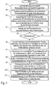
- das erfindungsgemäße Fehlerprotokollierungsverfahren in Form eines Flussdiagramms sowie
Figur 2- einen Bildschirmausdruck mit einer Fehlerkennung und zeitlich synchronisierten Prozessdatenverläufen.
- FIG. 1
- the error logging method according to the invention in the form of a flow chart and
- FIG. 2
- a screen shot with an error detection and temporally synchronized process data.
Im Folgenden wird nun unter Bezugnahme auf die Zeichnungen ein bevorzugtes Ausführungsbeispiel des erfindungsgemäßen Fehlerprotokollierungsverfahrens beschrieben.A preferred embodiment of the error logging method according to the invention will now be described with reference to the drawings.
In einem ersten Schritt S1 erfolgt eine laufende Messung von aktuellen Prozessdatensätzen der Beschichtungsanlage, wobei die einzelnen Prozessdatensätze jeweils eine Vielzahl von Prozessdaten der Beschichtungsanlage enthalten, wie beispielsweise die Ausflussmenge der einzelnen Medien (z.B. Lack, Lenkluft, Antriebsluft, etc.), die Drehzahl eines Rotationszerstäubers oder bauteilspezifische Daten, wie beispielsweise den Typ des aktuell lackierten Bauteils.In a first step S1, a current measurement of current process data records of the coating installation takes place, wherein the individual process data records each contain a multiplicity of process data of the coating installation, such as the outflow quantity of the individual media (eg paint, shaping air, drive air, etc.), the speed of a Rotationszerstäubers or component-specific data, such as the type of the currently painted component.
In einem weiteren Schritt S2 werden die gemessenen Prozessdatensätze dann in einem Zwischenspeicher zwischengespeichert, wobei es sich um einen Ringspeicher handelt, der beispielsweise eine Aufnahmezeit von einer Stunde oder mehreren Tagen aufweisen kann, so dass die Prozessdaten in dem Ringspeicher zyklisch überschrieben werden.In a further step S2, the measured process data sets are then buffered in a buffer, which is a ring buffer, which may have a recording time of one hour or several days, for example, so that the process data in the ring buffer are cyclically overwritten.
In einem weiteren Schritt S3 erfolgt dann eine Auswertung der in dem Zwischenspeicher gespeicherten Prozessdatensätze zur Detektion eines Fehlerzustands der Beschichtungsanlage und zur Bestimmung einer Fehlerkennung, die den Fehlertyp wiedergibt. Die Auswertung der in dem Zwischenspeicher gespeicherten Prozessdatensätze erfolgt im einfachsten Fall durch Vergleich der aktuellen Werte der Prozessdaten mit vorgegebenen Grenzwerten, so dass bei einer Grenzwertüberschreitung eine Fehlerdetektion erfolgt. Die Fehlerkennung kann dann im einfachsten Fall die Prozessdaten identifizieren, die den zulässigen Wertebereich verlassen haben.In a further step S3, an evaluation of the process data records stored in the intermediate memory is then carried out for the purpose of detecting an error state of the coating installation and for determining an error identifier which reproduces the error type. The evaluation of the process data sets stored in the buffer takes place in the simplest case by comparing the current values of the process data with predetermined limit values, so that when a limit value is exceeded, a Error detection takes place. In the simplest case, the error detection can then identify the process data that has left the permissible value range.
Darüber hinaus erfolgt in einem Schritt S4 eine Abfrage von Not-Aus-Schaltern der Beschichtungsanlage zur Detektion eines Fehlerzustands, wobei eine manuelle Betätigung des Not-Aus-Schalters durch eine Bedienungsperson einen Fehlerzustand anzeigt. Hierbei wird in Abhängigkeit von der Identifikationsnummer des betätigten Not-Aus-Schalters eine zugehörige Fehlerkennung generiert.In addition, in a step S4, an inquiry of emergency stop switches of the coating system for detecting an error condition, wherein a manual operation of the emergency stop switch by an operator indicates an error condition. In this case, an associated error identifier is generated in dependence on the identification number of the actuated emergency stop switch.
In einem weiteren Schritt S5 wird dann während des laufenden Betriebs der Beschichtungsanlage überprüft, ob ein Fehler detektiert wurde. Falls dies nicht der Fall ist, so wird der Betrieb der Beschichtungsanlage mit der laufenden Messung und Zwischenspeicherung der Prozessdatensätze fortgesetzt. Im Falle einer Fehlerdetektion werden dagegen in einem weiteren Schritt S6 diejenigen zwischengespeicherten Prozessdatensätze aus dem Zwischenspeicher ausgewählt, die innerhalb einer vorgegebenen Vorlaufzeit vor der Fehlerdetektion und innerhalb einer vorgegebenen Nachlaufzeit nach der Fehlerdetektion gemessen wurden. Die Vorlaufzeit und die Nachlaufzeit sind hierbei Zeitspannen, in denen eine bestimmte Anzahl von Skids bzw. Bauteilen durch die Anlage gefördert wird.In a further step S5 is then checked during operation of the coating system, whether an error has been detected. If this is not the case, the operation of the coating system continues with the ongoing measurement and buffering of the process data records. In the case of error detection, on the other hand, in a further step S6, those buffered process data records are selected from the buffer memory, which were measured within a predetermined lead time before the error detection and within a predetermined after-run time after the error detection. The lead time and the follow-up time here are periods in which a certain number of skids or components is conveyed through the system.
Die in dem Schritt S6 ausgewählten fehlerrelevanten Prozessdatensätze werden dann in einem weiteren Schritt S7 zusammen mit der zugehörigen Fehlerkennung in zeitlich synchronisierter Form in einer individuellen Fehlerdatei für jeden Fehler abgespeichert.The error-relevant process data records selected in step S6 are then stored in a further step S7 together with the associated error identifier in time-synchronized form in an individual error file for each error.
In einem weiteren Schritt S8 erfolgt dann eine grafische Darstellung der in der Fehlerdatei gespeicherten Prozessdatensätze auf einem Bildschirm beim Betreiber der Beschichtungsanlage, wie in
So zeigt
Darüber hinaus ist in dem Bildschirm eine Fehlerkennung 3 dargestellt, die den exakten Fehlerzeitpunkt angibt und somit eine intuitive zeitliche Zuordnung zu den dargestellten Prozessdaten ermöglicht.In addition, an error identifier 3 is shown in the screen, which indicates the exact error time and thus allows an intuitive temporal assignment to the process data shown.
Weiterhin sind auf dem Bildschirm mehrere Parameterachsen 4, 5 für die verschiedenen Prozessdaten abgebildet, wobei die Parameterachse 4 beispielsweise die Hochspannung eines elektrostatischen Rotationszerstäubers in kV angibt, während die Parameterachse 5 den elektrischen Strom in µA angibt. Der Benutzer kann jedoch andere Parameterachsen ein- bzw. ausblenden. Das Gleiche gilt auch für die Auswahl der auf dem Bildschirm dargestellten Prozessdaten, so dass der Benutzer in einfacher Weise diejenigen Prozessdaten auswählen und auf dem Bildschirm anzeigen lassen kann, die für eine Fehleranalyse wichtig sind.Furthermore,
Darüber hinaus ist auf dem Bildschirm ein Fenster 6 dargestellt, in dem die räumliche Lage der einzelnen Applikations- bzw. Handhabungsroboter in einer Perspektivansicht dargestellt ist, um eine intuitive Fehlererkennung zu ermöglichen.In addition, a
Nach dem Schritt S8 erfolgt in einem weiteren Schritt S9 eine Fehlerauswertung durch ein rechnergestütztes Expertensystem beim Betreiber der Lackieranlage zur Ermittlung von möglichen Fehlerursachen und Gegenmaßnahmen, die dann in einem Schritt S10 in einem Fenster 7 auf dem Bildschirm dargestellt werden. In einem weiteren Schritt S11 erfolgt dann eine Datenfernübertragung der Fehlerdatei vom Betreiber der Lackieranlage zum Hersteller der Lackieranlage, wo dann eine Fehlerauswertung durch Spezialisten des Herstellers erfolgen kann.After step S8, in a further step S9, an error evaluation by a computer-aided expert system is carried out by the operator of the paint shop to determine possible causes of errors and countermeasures, which are then displayed in a
Die Erfindung ist nicht auf das vorstehend beschriebene Ausführungsbeispiel beschränkt. Vielmehr ist eine Vielzahl von Varianten und Abwandlungen möglich, die in den Schutzbereich fallen, der durch die Ansprüche definiert ist.The invention is not limited to the embodiment described above. Rather, a variety of variants and modifications are possible, which fall within the scope defined by the claims.
Claims (15)
- An error logging method for a plant with the following steps:a) Continuous logging (S1) of process data sets of the plant, the individual process data sets each being attributed to certain points in plant operating time and each containing multiple process data of the plant,b) Detection (S3, S4, S5) of a possible error state of the plant;c) Storage (S2, S7) of those process data sets which were detected within a specified lead time before detection of the error state and/or within a specified follow-up time after detection of the error state,d) Generation (S3, S4) of an error code when a plant error state is detected;e) Storage (S7) of the error codecharacterizede1) time-synchronised with the stored process data sets and/ore2) with the relevant process data sets for each error state in a dedicated error file, and/ore3) with those process data sets which have been logged within a specified time frame around the time at which the error state was detected,f) in that the plant is a coating plant,g) in that the following coating plant process data are stored:g1) Component data characteristics of the coated components,g2) User data, characterising the interaction between an operator and the coating plant, and/org3) Plant data characterising the coating plant itself,h) in that the lead time and/or the follow-up time is a specific period, within which a specific number of skids or components to be coated is conveyed through the coating plant, andi) in that the storage (S2, S7) of the process data sets and the error code takes place with temporal resolution of at least 10 ms.
- The error logging method in accordance with claim 1, characterised in that the individual error codes and the relevant process data sets for each coating plant error state are each stored in a dedicated error file.
- The error logging method in accordance with any one of the preceding claims, characterised in thata) the error code is a timestamp (3) which reproduces the time of the error, and/orb) the error code shows the type of error detected.
- The error logging method in accordance with any one of the preceding claims, characterised in thata) the lead time and/or follow-up time for storage of the process data sets is at least 200ms, 1s, 5s, 10s, 1min, 1h or 1 day, orb) corresponds to a period in which at least one skid or at least ten skids are conveyed through the coating plant.
- The error logging method in accordance with one of the preceding claims, characterised in that the following coating plant process data are stored:a) Time and/orb) Sensor data, which reproduces the measurement signals from sensors, and/or:c) Colour of the coating agent currently being applied in the coating plant and/ord) Colour of the coating agent previously applied in the coating plant, and/ore) Identification number of the skid currently located in the coating plant and/orf) Identification number of the component currently located in the coating plant, particularly a body, or the components currently located in the coating plant, and/org) Type of component or components currently located in the coating plant, and/orh) Identification number of the looped main of the coating plant currently in use, and/ori) Identification number of the colour used, and/orj) Speed of a rotary atomiser, and/ork) Electrical charging voltage of an electrostatic application device, and/or1) Electric charging current of an electrostatic application device, and/orm) Volume of the coating agent currently being applied, and/orn) Flow rate of the individual media, particularly flushing agents, solvents, guide air, shroud air for flat spray, knife air, envelope air, drying air, cooling air, turbine bearing air, and/oro) Current flow of the individual guide air currents, and/orp) Current guide air pressure, and/orq) Current horn air flow and/or current horn air pressure, and/orr) Current driving air flow and/or current driving air pressure, and/ors) Paint pressure, and/ort) Air pressure and all available air pressure sensor measurementsu) Flushing agent pressure, and/orv) Pig positions, and/orw) Temperatures in the coating plant, and/orx) Moisture in the coating plant, and/ory) Paint cabin status, particularly ventilation status, water washout status, extraction statusz) Coating plant filling levels, and/oraa) Coating plant valve switch positions, and/orbb) Position, speed, acceleration and/or torque of a painting robot and/orcc) Target/actual deviation of one or more of the aforementioned process data, and/ordd) User entries, and/oree) Brush data, movement program number of the robot, and/orff) Conveyor data, particularly conveyor increments and status, and/orgg) Dryer data and status, and/orhh) Exchange of data between the control components.
- The error logging method in accordance with any one of the preceding claims, characterised by the following step (S11): remote transmission of the data sets logged and/or the error code to a maintenance service.
- The error logging method in accordance with any one of the preceding claims, characterised by the following steps:a) Storage of the process data sets and/or the error code on an interchangeable mass storage medium;b) Transport of the mass storage medium and the stored process data sets to a maintenance service.
- The error logging method in accordance with any one of the preceding claims, characterised in that detection (S3, S4) of the error state of the coating plant is computer controlled, using analysis of the process data sets of the coating plant, and/or is user-controlled by an operator.
- The error logging method in accordance with claim 8, characterised in that the time curves of the process data sets logged are compared with specified error curves within the scope of analysis of the process data sets for detecting an error state.
- The error logging method in accordance with any one of the preceding claims, characterised by the following steps:a) Readout of the stored data code and relevant process data sets;b) Visual display of the read-out error code and relevant process data sets on a monitor.
- The error logging method in accordance with any one of the preceding claims, characterised in thata) the stored process data sets also reproduce the spatial position of a coating plant robot;b) the position of the robot is graphically displayed on the screen in the visual display.
- The error logging method accordance with any one of the preceding claims, characterised in thata) certain process data are selected from the stored process data as a function of the error code;b) only the selected process data are displayed visually, to facilitate error analysis.
- The error logging method in accordance with any one of the preceding claims, characterised by the following steps:a) Computer-controlled determination (S9) of possible causes of errors and/or remedial measures from the stored error code and relevant process data sets;b) Visual display (S10) of possible causes of errors and/or remedial measures on screen.
- The error logging method in accordance with any one of the preceding claims, characterised by the following step:suppression of error detection within a specific period following error detection.
- A data storage medium with a computer program for running an error logging method on a computer in accordance with any one of the preceding claims.
Priority Applications (1)
| Application Number | Priority Date | Filing Date | Title |
|---|---|---|---|
| PL07819667T PL2095336T3 (en) | 2006-12-01 | 2007-11-07 | Error logging method for a coating plant |
Applications Claiming Priority (2)
| Application Number | Priority Date | Filing Date | Title |
|---|---|---|---|
| DE102006056879A DE102006056879A1 (en) | 2006-12-01 | 2006-12-01 | Error logging procedure for a coating plant |
| PCT/EP2007/009657 WO2008064763A1 (en) | 2006-12-01 | 2007-11-07 | Error logging method for a coating plant |
Publications (2)
| Publication Number | Publication Date |
|---|---|
| EP2095336A1 EP2095336A1 (en) | 2009-09-02 |
| EP2095336B1 true EP2095336B1 (en) | 2017-06-07 |
Family
ID=39092064
Family Applications (1)
| Application Number | Title | Priority Date | Filing Date |
|---|---|---|---|
| EP07819667.2A Active EP2095336B1 (en) | 2006-12-01 | 2007-11-07 | Error logging method for a coating plant |
Country Status (10)
| Country | Link |
|---|---|
| US (1) | US9582942B2 (en) |
| EP (1) | EP2095336B1 (en) |
| JP (1) | JP5769373B2 (en) |
| CN (1) | CN101622649B (en) |
| DE (1) | DE102006056879A1 (en) |
| ES (1) | ES2639408T3 (en) |
| HU (1) | HUE034484T2 (en) |
| PL (1) | PL2095336T3 (en) |
| RU (1) | RU2454722C2 (en) |
| WO (1) | WO2008064763A1 (en) |
Cited By (1)
| Publication number | Priority date | Publication date | Assignee | Title |
|---|---|---|---|---|
| DE102021121320A1 (en) | 2021-08-17 | 2023-02-23 | Dürr Systems Ag | Operating procedure for a coating plant and coating plant for carrying out the operating procedure |
Families Citing this family (25)
| Publication number | Priority date | Publication date | Assignee | Title |
|---|---|---|---|---|
| DE102009013561A1 (en) | 2009-03-17 | 2010-10-07 | Dürr Systems GmbH | Monitoring method and monitoring device for an electrostatic coating system |
| DE102010048810A1 (en) | 2010-10-20 | 2012-04-26 | Hüttinger Elektronik Gmbh + Co. Kg | System for operating multiple plasma and / or induction heating processes |
| DE102010048809A1 (en) | 2010-10-20 | 2012-04-26 | Hüttinger Elektronik Gmbh + Co. Kg | Power supply system for a plasma application and / or an induction heating application |
| US8782026B2 (en) | 2011-03-31 | 2014-07-15 | Honda Motor Co., Ltd. | Color harmony with process and environmental feedback |
| US8708202B2 (en) | 2011-05-10 | 2014-04-29 | Ppg Industries Ohio, Inc. | Pressure canisters for automated delivery of coating compositions |
| US8989904B2 (en) * | 2012-02-27 | 2015-03-24 | Fanuc Robotics America Corporation | Robotic process logger |
| US8904243B2 (en) * | 2012-06-29 | 2014-12-02 | Sap Se | Event management systems and methods |
| US9849431B2 (en) | 2012-07-13 | 2017-12-26 | Ppg Industries Ohio, Inc. | System and method for automated production, application and evaluation of coating compositions |
| DE112013006802T5 (en) * | 2013-04-04 | 2015-12-03 | Mitsubishi Electric Corporation | Engineering tool and programmable logic controller |
| EP2884362B1 (en) * | 2013-12-13 | 2020-02-12 | Robert Bosch Gmbh | Method for running a working machine with fault control |
| JP6510761B2 (en) * | 2014-04-08 | 2019-05-08 | 川崎重工業株式会社 | Data acquisition system and method |
| JP6350011B2 (en) * | 2014-06-20 | 2018-07-04 | オムロン株式会社 | Robot control system |
| CN104155973B (en) * | 2014-09-02 | 2017-05-17 | 深圳市浩能科技有限公司 | Clearance coating fault testing method and system |
| CA2974835A1 (en) * | 2015-02-05 | 2016-08-11 | Carlisle Fluid Technologies, Inc. | Spray tool system |
| US10324428B2 (en) | 2015-02-12 | 2019-06-18 | Carlisle Fluid Technologies, Inc. | Intra-shop connectivity system |
| FR3036298B1 (en) * | 2015-05-21 | 2017-05-05 | Renault Sas | PAINT DISTRIBUTION SYSTEM FOR A MOTOR VEHICLE CASE |
| US11273462B2 (en) | 2015-11-26 | 2022-03-15 | Carlisle Fluid Technologies, Inc. | Sprayer system |
| US11048226B2 (en) | 2016-09-09 | 2021-06-29 | Fanuc America Corporation | Program and variable change analysis |
| JP6277303B1 (en) * | 2017-05-09 | 2018-02-07 | 長瀬産業株式会社 | Painting equipment |
| EP3582051A1 (en) | 2018-06-12 | 2019-12-18 | Siemens Aktiengesellschaft | Comprehensive fault analysis for control devices and industrial technical installations |
| PT3966646T (en) * | 2019-05-09 | 2024-02-21 | Duerr Systems Ag | Method for analysing quality defects |
| US11927946B2 (en) | 2019-05-09 | 2024-03-12 | Dürr Systems Ag | Analysis method and devices for same |
| EP3966648A1 (en) * | 2019-05-09 | 2022-03-16 | Dürr Systems AG | Analysis method and devices therefor |
| DE102019206839A1 (en) * | 2019-05-10 | 2020-11-12 | Dürr Systems Ag | Analysis methods and devices for this |
| EP3966650B1 (en) | 2019-05-09 | 2024-03-06 | Dürr Systems AG | Method for control and after-treatment of workpieces, control system and treatment installation |
Family Cites Families (33)
| Publication number | Priority date | Publication date | Assignee | Title |
|---|---|---|---|---|
| DE3224586A1 (en) * | 1982-07-01 | 1984-01-05 | Bayerische Motoren Werke AG, 8000 München | Operating data acquisition device |
| DE4228281A1 (en) * | 1992-08-26 | 1994-03-03 | Koenig & Bauer Ag | Process for displaying machine malfunctions |
| JPH06149347A (en) * | 1992-11-05 | 1994-05-27 | Kawasaki Steel Corp | Abnormality reproducing device for equipment |
| US5481260A (en) * | 1994-03-28 | 1996-01-02 | Nordson Corporation | Monitor for fluid dispensing system |
| JP3512494B2 (en) * | 1994-11-30 | 2004-03-29 | 株式会社東芝 | Plant operation support device |
| JPH08314539A (en) * | 1995-05-16 | 1996-11-29 | Fuji Electric Co Ltd | Data collection method for abnormality analysis |
| US6522939B1 (en) * | 1996-07-01 | 2003-02-18 | Robert D. Strauch | Computer system for quality control correlation |
| JP3352411B2 (en) * | 1998-03-05 | 2002-12-03 | 株式会社東芝 | Control system, power system protection control system, and storage medium storing program |
| JPH11331766A (en) * | 1998-05-15 | 1999-11-30 | Omron Corp | Equipment logging device |
| KR100313553B1 (en) * | 1998-06-25 | 2001-11-07 | 이마이 기요스케 | Remote supervisory control system |
| JP2000065694A (en) * | 1998-08-25 | 2000-03-03 | Toshiba Corp | Apparatus for searching generation cause of abnormality |
| JP2000099141A (en) * | 1998-09-22 | 2000-04-07 | Toshiba Corp | Plant data collection and analysis system, and plant data analyzer |
| JP2000235412A (en) * | 1999-02-15 | 2000-08-29 | Omron Corp | Logging device |
| US6298454B1 (en) | 1999-02-22 | 2001-10-02 | Fisher-Rosemount Systems, Inc. | Diagnostics in a process control system |
| JP2000288876A (en) * | 1999-04-07 | 2000-10-17 | Canon Inc | Production control device and production control method |
| JP2002049414A (en) * | 2000-05-26 | 2002-02-15 | Yutaka Electronics Industry Co Ltd | Maintenance method for industrial machine and system for the same |
| SE518642C2 (en) * | 2000-07-11 | 2002-11-05 | Mydata Automation Ab | Method, device for providing a substrate with viscous medium, device for correcting application errors and the use of projecting means for correcting application errors |
| DE10036741A1 (en) * | 2000-07-27 | 2002-02-07 | Duerr Systems Gmbh | Process and control system for checking the coating quality of workpieces |
| EP1307816A1 (en) * | 2000-08-09 | 2003-05-07 | ABB Research Ltd. | System for determining error causes |
| DE10150826A1 (en) * | 2001-10-15 | 2003-04-17 | Duerr Systems Gmbh | Method and program control system for controlling a coating system |
| JP3631204B2 (en) * | 2001-12-28 | 2005-03-23 | 川崎重工業株式会社 | Failure diagnosis system, failure diagnosis apparatus, and computer program |
| US7117079B2 (en) * | 2002-02-05 | 2006-10-03 | Cleaire Advanced Emission Controls, Llc | Apparatus and method for simultaneous monitoring, logging, and controlling of an industrial process |
| JP4348895B2 (en) * | 2002-03-29 | 2009-10-21 | トヨタ自動車株式会社 | System and management method for managing paint quality of automobile body group |
| JP4025187B2 (en) * | 2002-12-19 | 2007-12-19 | 東京瓦斯株式会社 | Relay adapter and remote management system |
| JP4311029B2 (en) * | 2003-02-03 | 2009-08-12 | トヨタ自動車株式会社 | Production equipment condition analyzer |
| US7139965B2 (en) * | 2003-10-08 | 2006-11-21 | Hewlett-Packard Development Company, L.P. | Bus device that concurrently synchronizes source synchronous data while performing error detection and correction |
| JP4495960B2 (en) * | 2003-12-26 | 2010-07-07 | キヤノンItソリューションズ株式会社 | Model creation device for the relationship between process and quality |
| JP2005313077A (en) * | 2004-04-28 | 2005-11-10 | Nippon Paint Co Ltd | Coating condition setting system |
| JP3744527B2 (en) * | 2004-06-07 | 2006-02-15 | オムロン株式会社 | Process management device, process management method, process management program, and recording medium recording the program |
| JP4161276B2 (en) * | 2004-12-17 | 2008-10-08 | 日本電気株式会社 | Fault-tolerant computer device and synchronization method thereof |
| AU2006213373B2 (en) * | 2005-02-14 | 2009-06-18 | Komatsu Ltd. | Working machine failure information centralized managing system |
| DE102005024010B4 (en) * | 2005-05-20 | 2013-07-04 | Schott Ag | Coating plant with facilities for testing and service routines and procedures for carrying out inspection and service routines in coating plants |
| US8726091B2 (en) * | 2011-06-24 | 2014-05-13 | Rockwell Automation Technologies, Inc. | Troubleshooting system for industrial control programs |
-
2006
- 2006-12-01 DE DE102006056879A patent/DE102006056879A1/en not_active Withdrawn
-
2007
- 2007-11-07 EP EP07819667.2A patent/EP2095336B1/en active Active
- 2007-11-07 US US12/517,131 patent/US9582942B2/en active Active
- 2007-11-07 HU HUE07819667A patent/HUE034484T2/en unknown
- 2007-11-07 ES ES07819667.2T patent/ES2639408T3/en active Active
- 2007-11-07 RU RU2009125058/08A patent/RU2454722C2/en active
- 2007-11-07 PL PL07819667T patent/PL2095336T3/en unknown
- 2007-11-07 JP JP2009538607A patent/JP5769373B2/en active Active
- 2007-11-07 WO PCT/EP2007/009657 patent/WO2008064763A1/en active Application Filing
- 2007-11-07 CN CN2007800444922A patent/CN101622649B/en active Active
Non-Patent Citations (1)
| Title |
|---|
| None * |
Cited By (2)
| Publication number | Priority date | Publication date | Assignee | Title |
|---|---|---|---|---|
| DE102021121320A1 (en) | 2021-08-17 | 2023-02-23 | Dürr Systems Ag | Operating procedure for a coating plant and coating plant for carrying out the operating procedure |
| WO2023020821A1 (en) | 2021-08-17 | 2023-02-23 | Dürr Systems Ag | Operating method for a coating system, and coating system for carrying out the operating method |
Also Published As
| Publication number | Publication date |
|---|---|
| DE102006056879A1 (en) | 2008-06-05 |
| PL2095336T3 (en) | 2017-11-30 |
| JP2010511232A (en) | 2010-04-08 |
| WO2008064763A1 (en) | 2008-06-05 |
| EP2095336A1 (en) | 2009-09-02 |
| CN101622649A (en) | 2010-01-06 |
| HUE034484T2 (en) | 2018-02-28 |
| US9582942B2 (en) | 2017-02-28 |
| RU2009125058A (en) | 2011-01-10 |
| CN101622649B (en) | 2012-03-07 |
| ES2639408T3 (en) | 2017-10-26 |
| JP5769373B2 (en) | 2015-08-26 |
| US20100161141A1 (en) | 2010-06-24 |
| RU2454722C2 (en) | 2012-06-27 |
Similar Documents
| Publication | Publication Date | Title |
|---|---|---|
| EP2095336B1 (en) | Error logging method for a coating plant | |
| DE102012202914A1 (en) | Diagnostic method and diagnostic device for a vehicle component of a vehicle | |
| DE102017200855A1 (en) | Method and system for diagnosing components of a vehicle | |
| EP3681754B1 (en) | Method for detecting profiles of charging currents | |
| EP2097175A1 (en) | Test method and test device for functional testing of a painting device | |
| EP1891606A1 (en) | Method for the model-based diagnosis of a mechatronic system | |
| EP2047118B1 (en) | Method for fault localization and diagnosis in a fluidic installation | |
| EP3546314A1 (en) | Method and device for fault identification for a technical system | |
| WO2023117318A1 (en) | Method for forecasting the energy requirement of a motor vehicle | |
| DE102007039793A1 (en) | Pneumatic system e.g. pneumatic brake system, monitoring method for commercial motor vehicle, involves detecting pressure signal continuously in pneumatic system, and analyzing resulting time response of detected pressure values | |
| DE19903826B4 (en) | System for monitoring a production plant | |
| EP3141867B1 (en) | Method and device for synchronizing a first local environment map with a second local environment map in an environment of a motor vehicle | |
| EP1398238B1 (en) | Diagnosis and monitoring device for a brake actuating device for a vehicle | |
| DE102015210716B4 (en) | Position sensor and method for operating a position sensor | |
| EP2957075A1 (en) | Master bus device for a vehicle communication bus of a motor vehicle | |
| EP3268822B1 (en) | Projecting device and method for configuring and/or parameterising automation components of an automation system | |
| EP1747380B1 (en) | Method for fault localisation and diagnosis in a fluidic installation | |
| DE102016224193A1 (en) | Method for monitoring a control device for a vehicle | |
| DE102007059201A1 (en) | Motor vehicle manufacturing method, involves performing assembling process, and connecting stations and terminals with central shop server, and displaying centrally controlled data by visual representation of process | |
| DE102021126188A1 (en) | Monitoring method for a robot and associated robotic system | |
| DE102014207282A1 (en) | Method for diagnosing a motor vehicle system, diagnostic device for a motor vehicle system, control device for a motor vehicle system and motor vehicle | |
| WO2020127403A1 (en) | Method for determining tolerances of components or assemblies | |
| EP3792138A1 (en) | Door system for a vehicle and method and device for providing maintenance information for a door system for a vehicle | |
| EP1117023B1 (en) | Device for fault diagnosis during motor vehicle operation | |
| DE102012015783A1 (en) | Method for diagnosing several vehicle components of motor car, involves actuating determined diagnostic unit by control device so that supplementary diagnosis data is provided to assigned vehicle component from diagnostic unit |
Legal Events
| Date | Code | Title | Description |
|---|---|---|---|
| PUAI | Public reference made under article 153(3) epc to a published international application that has entered the european phase |
Free format text: ORIGINAL CODE: 0009012 |
|
| 17P | Request for examination filed |
Effective date: 20080331 |
|
| AK | Designated contracting states |
Kind code of ref document: A1 Designated state(s): AT BE BG CH CY CZ DE DK EE ES FI FR GB GR HU IE IS IT LI LT LU LV MC MT NL PL PT RO SE SI SK TR |
|
| RAP1 | Party data changed (applicant data changed or rights of an application transferred) |
Owner name: DUERR SYSTEMS GMBH |
|
| DAX | Request for extension of the european patent (deleted) | ||
| 17Q | First examination report despatched |
Effective date: 20150821 |
|
| RAP1 | Party data changed (applicant data changed or rights of an application transferred) |
Owner name: DUERR SYSTEMS AG |
|
| GRAP | Despatch of communication of intention to grant a patent |
Free format text: ORIGINAL CODE: EPIDOSNIGR1 |
|
| STAA | Information on the status of an ep patent application or granted ep patent |
Free format text: STATUS: GRANT OF PATENT IS INTENDED |
|
| INTG | Intention to grant announced |
Effective date: 20170327 |
|
| GRAS | Grant fee paid |
Free format text: ORIGINAL CODE: EPIDOSNIGR3 |
|
| GRAA | (expected) grant |
Free format text: ORIGINAL CODE: 0009210 |
|
| STAA | Information on the status of an ep patent application or granted ep patent |
Free format text: STATUS: THE PATENT HAS BEEN GRANTED |
|
| AK | Designated contracting states |
Kind code of ref document: B1 Designated state(s): AT BE BG CH CY CZ DE DK EE ES FI FR GB GR HU IE IS IT LI LT LU LV MC MT NL PL PT RO SE SI SK TR |
|
| REG | Reference to a national code |
Ref country code: GB Ref legal event code: FG4D Free format text: NOT ENGLISH |
|
| GRAA | (expected) grant |
Free format text: ORIGINAL CODE: 0009210 |
|
| REG | Reference to a national code |
Ref country code: CH Ref legal event code: EP Ref country code: AT Ref legal event code: REF Ref document number: 899733 Country of ref document: AT Kind code of ref document: T Effective date: 20170615 |
|
| REG | Reference to a national code |
Ref country code: IE Ref legal event code: FG4D Free format text: LANGUAGE OF EP DOCUMENT: GERMAN |
|
| REG | Reference to a national code |
Ref country code: DE Ref legal event code: R096 Ref document number: 502007015688 Country of ref document: DE |
|
| REG | Reference to a national code |
Ref country code: SE Ref legal event code: TRGR |
|
| REG | Reference to a national code |
Ref country code: NL Ref legal event code: MP Effective date: 20170607 |
|
| REG | Reference to a national code |
Ref country code: LT Ref legal event code: MG4D |
|
| REG | Reference to a national code |
Ref country code: ES Ref legal event code: FG2A Ref document number: 2639408 Country of ref document: ES Kind code of ref document: T3 Effective date: 20171026 |
|
| PG25 | Lapsed in a contracting state [announced via postgrant information from national office to epo] |
Ref country code: LT Free format text: LAPSE BECAUSE OF FAILURE TO SUBMIT A TRANSLATION OF THE DESCRIPTION OR TO PAY THE FEE WITHIN THE PRESCRIBED TIME-LIMIT Effective date: 20170607 Ref country code: GR Free format text: LAPSE BECAUSE OF FAILURE TO SUBMIT A TRANSLATION OF THE DESCRIPTION OR TO PAY THE FEE WITHIN THE PRESCRIBED TIME-LIMIT Effective date: 20170908 Ref country code: FI Free format text: LAPSE BECAUSE OF FAILURE TO SUBMIT A TRANSLATION OF THE DESCRIPTION OR TO PAY THE FEE WITHIN THE PRESCRIBED TIME-LIMIT Effective date: 20170607 |
|
| REG | Reference to a national code |
Ref country code: FR Ref legal event code: PLFP Year of fee payment: 11 |
|
| PG25 | Lapsed in a contracting state [announced via postgrant information from national office to epo] |
Ref country code: NL Free format text: LAPSE BECAUSE OF FAILURE TO SUBMIT A TRANSLATION OF THE DESCRIPTION OR TO PAY THE FEE WITHIN THE PRESCRIBED TIME-LIMIT Effective date: 20170607 Ref country code: LV Free format text: LAPSE BECAUSE OF FAILURE TO SUBMIT A TRANSLATION OF THE DESCRIPTION OR TO PAY THE FEE WITHIN THE PRESCRIBED TIME-LIMIT Effective date: 20170607 Ref country code: BG Free format text: LAPSE BECAUSE OF FAILURE TO SUBMIT A TRANSLATION OF THE DESCRIPTION OR TO PAY THE FEE WITHIN THE PRESCRIBED TIME-LIMIT Effective date: 20170907 |
|
| PG25 | Lapsed in a contracting state [announced via postgrant information from national office to epo] |
Ref country code: EE Free format text: LAPSE BECAUSE OF FAILURE TO SUBMIT A TRANSLATION OF THE DESCRIPTION OR TO PAY THE FEE WITHIN THE PRESCRIBED TIME-LIMIT Effective date: 20170607 Ref country code: RO Free format text: LAPSE BECAUSE OF FAILURE TO SUBMIT A TRANSLATION OF THE DESCRIPTION OR TO PAY THE FEE WITHIN THE PRESCRIBED TIME-LIMIT Effective date: 20170607 |
|
| PG25 | Lapsed in a contracting state [announced via postgrant information from national office to epo] |
Ref country code: IS Free format text: LAPSE BECAUSE OF FAILURE TO SUBMIT A TRANSLATION OF THE DESCRIPTION OR TO PAY THE FEE WITHIN THE PRESCRIBED TIME-LIMIT Effective date: 20171007 |
|
| REG | Reference to a national code |
Ref country code: HU Ref legal event code: AG4A Ref document number: E034484 Country of ref document: HU Ref country code: HU Ref legal event code: HC9C |
|
| REG | Reference to a national code |
Ref country code: DE Ref legal event code: R097 Ref document number: 502007015688 Country of ref document: DE |
|
| PLBE | No opposition filed within time limit |
Free format text: ORIGINAL CODE: 0009261 |
|
| STAA | Information on the status of an ep patent application or granted ep patent |
Free format text: STATUS: NO OPPOSITION FILED WITHIN TIME LIMIT |
|
| PG25 | Lapsed in a contracting state [announced via postgrant information from national office to epo] |
Ref country code: DK Free format text: LAPSE BECAUSE OF FAILURE TO SUBMIT A TRANSLATION OF THE DESCRIPTION OR TO PAY THE FEE WITHIN THE PRESCRIBED TIME-LIMIT Effective date: 20170607 |
|
| 26N | No opposition filed |
Effective date: 20180308 |
|
| PG25 | Lapsed in a contracting state [announced via postgrant information from national office to epo] |
Ref country code: SI Free format text: LAPSE BECAUSE OF FAILURE TO SUBMIT A TRANSLATION OF THE DESCRIPTION OR TO PAY THE FEE WITHIN THE PRESCRIBED TIME-LIMIT Effective date: 20170607 |
|
| PG25 | Lapsed in a contracting state [announced via postgrant information from national office to epo] |
Ref country code: MC Free format text: LAPSE BECAUSE OF FAILURE TO SUBMIT A TRANSLATION OF THE DESCRIPTION OR TO PAY THE FEE WITHIN THE PRESCRIBED TIME-LIMIT Effective date: 20170607 |
|
| PG25 | Lapsed in a contracting state [announced via postgrant information from national office to epo] |
Ref country code: LI Free format text: LAPSE BECAUSE OF NON-PAYMENT OF DUE FEES Effective date: 20171130 Ref country code: CH Free format text: LAPSE BECAUSE OF NON-PAYMENT OF DUE FEES Effective date: 20171130 |
|
| PG25 | Lapsed in a contracting state [announced via postgrant information from national office to epo] |
Ref country code: LU Free format text: LAPSE BECAUSE OF NON-PAYMENT OF DUE FEES Effective date: 20171107 |
|
| REG | Reference to a national code |
Ref country code: BE Ref legal event code: MM Effective date: 20171130 |
|
| REG | Reference to a national code |
Ref country code: IE Ref legal event code: MM4A |
|
| PG25 | Lapsed in a contracting state [announced via postgrant information from national office to epo] |
Ref country code: MT Free format text: LAPSE BECAUSE OF FAILURE TO SUBMIT A TRANSLATION OF THE DESCRIPTION OR TO PAY THE FEE WITHIN THE PRESCRIBED TIME-LIMIT Effective date: 20170607 |
|
| PG25 | Lapsed in a contracting state [announced via postgrant information from national office to epo] |
Ref country code: IE Free format text: LAPSE BECAUSE OF NON-PAYMENT OF DUE FEES Effective date: 20171107 |
|
| PG25 | Lapsed in a contracting state [announced via postgrant information from national office to epo] |
Ref country code: BE Free format text: LAPSE BECAUSE OF NON-PAYMENT OF DUE FEES Effective date: 20171130 |
|
| REG | Reference to a national code |
Ref country code: AT Ref legal event code: MM01 Ref document number: 899733 Country of ref document: AT Kind code of ref document: T Effective date: 20171107 |
|
| PG25 | Lapsed in a contracting state [announced via postgrant information from national office to epo] |
Ref country code: AT Free format text: LAPSE BECAUSE OF NON-PAYMENT OF DUE FEES Effective date: 20171107 |
|
| PG25 | Lapsed in a contracting state [announced via postgrant information from national office to epo] |
Ref country code: CY Free format text: LAPSE BECAUSE OF NON-PAYMENT OF DUE FEES Effective date: 20170607 |
|
| PG25 | Lapsed in a contracting state [announced via postgrant information from national office to epo] |
Ref country code: PT Free format text: LAPSE BECAUSE OF FAILURE TO SUBMIT A TRANSLATION OF THE DESCRIPTION OR TO PAY THE FEE WITHIN THE PRESCRIBED TIME-LIMIT Effective date: 20170607 |
|
| P01 | Opt-out of the competence of the unified patent court (upc) registered |
Effective date: 20230512 |
|
| PGFP | Annual fee paid to national office [announced via postgrant information from national office to epo] |
Ref country code: SK Payment date: 20231031 Year of fee payment: 17 |
|
| PGFP | Annual fee paid to national office [announced via postgrant information from national office to epo] |
Ref country code: GB Payment date: 20231123 Year of fee payment: 17 |
|
| PGFP | Annual fee paid to national office [announced via postgrant information from national office to epo] |
Ref country code: TR Payment date: 20231106 Year of fee payment: 17 Ref country code: SE Payment date: 20231120 Year of fee payment: 17 Ref country code: IT Payment date: 20231121 Year of fee payment: 17 Ref country code: HU Payment date: 20231122 Year of fee payment: 17 Ref country code: FR Payment date: 20231120 Year of fee payment: 17 Ref country code: DE Payment date: 20231121 Year of fee payment: 17 Ref country code: CZ Payment date: 20231027 Year of fee payment: 17 |
|
| PGFP | Annual fee paid to national office [announced via postgrant information from national office to epo] |
Ref country code: PL Payment date: 20231026 Year of fee payment: 17 |
|
| PGFP | Annual fee paid to national office [announced via postgrant information from national office to epo] |
Ref country code: ES Payment date: 20240126 Year of fee payment: 17 |