EP2095104B1 - Abbildung zweidimensionaler arrays - Google Patents
Abbildung zweidimensionaler arrays Download PDFInfo
- Publication number
- EP2095104B1 EP2095104B1 EP07865871.3A EP07865871A EP2095104B1 EP 2095104 B1 EP2095104 B1 EP 2095104B1 EP 07865871 A EP07865871 A EP 07865871A EP 2095104 B1 EP2095104 B1 EP 2095104B1
- Authority
- EP
- European Patent Office
- Prior art keywords
- sample
- light
- light source
- area
- line
- Prior art date
- Legal status (The legal status is an assumption and is not a legal conclusion. Google has not performed a legal analysis and makes no representation as to the accuracy of the status listed.)
- Not-in-force
Links
- 238000003384 imaging method Methods 0.000 title description 18
- 238000003491 array Methods 0.000 title description 2
- 239000000523 sample Substances 0.000 claims description 146
- 238000000034 method Methods 0.000 claims description 24
- 238000005286 illumination Methods 0.000 claims description 22
- 230000010354 integration Effects 0.000 claims description 19
- 238000001514 detection method Methods 0.000 claims description 12
- 238000012545 processing Methods 0.000 claims description 10
- 239000012472 biological sample Substances 0.000 claims description 7
- OAICVXFJPJFONN-UHFFFAOYSA-N Phosphorus Chemical compound [P] OAICVXFJPJFONN-UHFFFAOYSA-N 0.000 claims description 5
- 238000004737 colorimetric analysis Methods 0.000 claims description 3
- 230000003287 optical effect Effects 0.000 claims description 3
- 230000005284 excitation Effects 0.000 description 16
- 239000000499 gel Substances 0.000 description 8
- 241000894007 species Species 0.000 description 6
- 238000000326 densiometry Methods 0.000 description 5
- 238000000926 separation method Methods 0.000 description 5
- 238000005259 measurement Methods 0.000 description 4
- 238000004458 analytical method Methods 0.000 description 2
- 239000002826 coolant Substances 0.000 description 2
- 238000001962 electrophoresis Methods 0.000 description 2
- 238000000799 fluorescence microscopy Methods 0.000 description 2
- 239000000203 mixture Substances 0.000 description 2
- 230000035945 sensitivity Effects 0.000 description 2
- 230000001360 synchronised effect Effects 0.000 description 2
- 241001562081 Ikeda Species 0.000 description 1
- 108091005461 Nucleic proteins Proteins 0.000 description 1
- VYPSYNLAJGMNEJ-UHFFFAOYSA-N Silicium dioxide Chemical compound O=[Si]=O VYPSYNLAJGMNEJ-UHFFFAOYSA-N 0.000 description 1
- BQCADISMDOOEFD-UHFFFAOYSA-N Silver Chemical compound [Ag] BQCADISMDOOEFD-UHFFFAOYSA-N 0.000 description 1
- 239000011543 agarose gel Substances 0.000 description 1
- 239000012062 aqueous buffer Substances 0.000 description 1
- 238000010276 construction Methods 0.000 description 1
- 238000007405 data analysis Methods 0.000 description 1
- 238000013461 design Methods 0.000 description 1
- 238000010586 diagram Methods 0.000 description 1
- 238000005516 engineering process Methods 0.000 description 1
- 230000002708 enhancing effect Effects 0.000 description 1
- 238000002474 experimental method Methods 0.000 description 1
- 239000012634 fragment Substances 0.000 description 1
- 239000005350 fused silica glass Substances 0.000 description 1
- 239000011521 glass Substances 0.000 description 1
- 238000002329 infrared spectrum Methods 0.000 description 1
- 238000011835 investigation Methods 0.000 description 1
- 238000001155 isoelectric focusing Methods 0.000 description 1
- 230000031700 light absorption Effects 0.000 description 1
- 239000007788 liquid Substances 0.000 description 1
- 239000012528 membrane Substances 0.000 description 1
- 238000002493 microarray Methods 0.000 description 1
- 102000039446 nucleic acids Human genes 0.000 description 1
- 108020004707 nucleic acids Proteins 0.000 description 1
- 150000007523 nucleic acids Chemical class 0.000 description 1
- 229920002401 polyacrylamide Polymers 0.000 description 1
- 102000004169 proteins and genes Human genes 0.000 description 1
- 230000002285 radioactive effect Effects 0.000 description 1
- 238000011160 research Methods 0.000 description 1
- 230000000717 retained effect Effects 0.000 description 1
- 229910052709 silver Inorganic materials 0.000 description 1
- 239000004332 silver Substances 0.000 description 1
- 238000001542 size-exclusion chromatography Methods 0.000 description 1
- 239000000243 solution Substances 0.000 description 1
- 239000000758 substrate Substances 0.000 description 1
- 239000012780 transparent material Substances 0.000 description 1
- 238000001429 visible spectrum Methods 0.000 description 1
Images

Classifications
-
- G—PHYSICS
- G01—MEASURING; TESTING
- G01N—INVESTIGATING OR ANALYSING MATERIALS BY DETERMINING THEIR CHEMICAL OR PHYSICAL PROPERTIES
- G01N27/00—Investigating or analysing materials by the use of electric, electrochemical, or magnetic means
- G01N27/26—Investigating or analysing materials by the use of electric, electrochemical, or magnetic means by investigating electrochemical variables; by using electrolysis or electrophoresis
- G01N27/416—Systems
- G01N27/447—Systems using electrophoresis
- G01N27/44704—Details; Accessories
- G01N27/44717—Arrangements for investigating the separated zones, e.g. localising zones
- G01N27/44721—Arrangements for investigating the separated zones, e.g. localising zones by optical means
- G01N27/44726—Arrangements for investigating the separated zones, e.g. localising zones by optical means using specific dyes, markers or binding molecules
-
- G—PHYSICS
- G01—MEASURING; TESTING
- G01N—INVESTIGATING OR ANALYSING MATERIALS BY DETERMINING THEIR CHEMICAL OR PHYSICAL PROPERTIES
- G01N21/00—Investigating or analysing materials by the use of optical means, i.e. using sub-millimetre waves, infrared, visible or ultraviolet light
- G01N21/17—Systems in which incident light is modified in accordance with the properties of the material investigated
- G01N21/59—Transmissivity
- G01N21/5907—Densitometers
- G01N21/5911—Densitometers of the scanning type
-
- G—PHYSICS
- G01—MEASURING; TESTING
- G01N—INVESTIGATING OR ANALYSING MATERIALS BY DETERMINING THEIR CHEMICAL OR PHYSICAL PROPERTIES
- G01N21/00—Investigating or analysing materials by the use of optical means, i.e. using sub-millimetre waves, infrared, visible or ultraviolet light
- G01N21/62—Systems in which the material investigated is excited whereby it emits light or causes a change in wavelength of the incident light
- G01N21/63—Systems in which the material investigated is excited whereby it emits light or causes a change in wavelength of the incident light optically excited
- G01N21/64—Fluorescence; Phosphorescence
- G01N21/645—Specially adapted constructive features of fluorimeters
- G01N21/6452—Individual samples arranged in a regular 2D-array, e.g. multiwell plates
-
- G—PHYSICS
- G01—MEASURING; TESTING
- G01N—INVESTIGATING OR ANALYSING MATERIALS BY DETERMINING THEIR CHEMICAL OR PHYSICAL PROPERTIES
- G01N21/00—Investigating or analysing materials by the use of optical means, i.e. using sub-millimetre waves, infrared, visible or ultraviolet light
- G01N21/62—Systems in which the material investigated is excited whereby it emits light or causes a change in wavelength of the incident light
- G01N21/63—Systems in which the material investigated is excited whereby it emits light or causes a change in wavelength of the incident light optically excited
- G01N21/64—Fluorescence; Phosphorescence
- G01N21/645—Specially adapted constructive features of fluorimeters
- G01N21/6456—Spatial resolved fluorescence measurements; Imaging
-
- G—PHYSICS
- G01—MEASURING; TESTING
- G01N—INVESTIGATING OR ANALYSING MATERIALS BY DETERMINING THEIR CHEMICAL OR PHYSICAL PROPERTIES
- G01N21/00—Investigating or analysing materials by the use of optical means, i.e. using sub-millimetre waves, infrared, visible or ultraviolet light
- G01N21/75—Systems in which material is subjected to a chemical reaction, the progress or the result of the reaction being investigated
- G01N21/76—Chemiluminescence; Bioluminescence
-
- G—PHYSICS
- G01—MEASURING; TESTING
- G01N—INVESTIGATING OR ANALYSING MATERIALS BY DETERMINING THEIR CHEMICAL OR PHYSICAL PROPERTIES
- G01N30/00—Investigating or analysing materials by separation into components using adsorption, absorption or similar phenomena or using ion-exchange, e.g. chromatography or field flow fractionation
- G01N30/90—Plate chromatography, e.g. thin layer or paper chromatography
- G01N30/95—Detectors specially adapted therefor; Signal analysis
-
- G—PHYSICS
- G01—MEASURING; TESTING
- G01N—INVESTIGATING OR ANALYSING MATERIALS BY DETERMINING THEIR CHEMICAL OR PHYSICAL PROPERTIES
- G01N21/00—Investigating or analysing materials by the use of optical means, i.e. using sub-millimetre waves, infrared, visible or ultraviolet light
- G01N21/62—Systems in which the material investigated is excited whereby it emits light or causes a change in wavelength of the incident light
- G01N21/63—Systems in which the material investigated is excited whereby it emits light or causes a change in wavelength of the incident light optically excited
- G01N21/64—Fluorescence; Phosphorescence
- G01N2021/6417—Spectrofluorimetric devices
- G01N2021/6419—Excitation at two or more wavelengths
-
- G—PHYSICS
- G01—MEASURING; TESTING
- G01N—INVESTIGATING OR ANALYSING MATERIALS BY DETERMINING THEIR CHEMICAL OR PHYSICAL PROPERTIES
- G01N21/00—Investigating or analysing materials by the use of optical means, i.e. using sub-millimetre waves, infrared, visible or ultraviolet light
- G01N21/62—Systems in which the material investigated is excited whereby it emits light or causes a change in wavelength of the incident light
- G01N21/63—Systems in which the material investigated is excited whereby it emits light or causes a change in wavelength of the incident light optically excited
- G01N21/64—Fluorescence; Phosphorescence
- G01N2021/6417—Spectrofluorimetric devices
- G01N2021/6421—Measuring at two or more wavelengths
-
- G—PHYSICS
- G01—MEASURING; TESTING
- G01N—INVESTIGATING OR ANALYSING MATERIALS BY DETERMINING THEIR CHEMICAL OR PHYSICAL PROPERTIES
- G01N2201/00—Features of devices classified in G01N21/00
- G01N2201/06—Illumination; Optics
- G01N2201/062—LED's
Definitions
- the component species of a mixture are identified by any of a variety of separation procedures, prominent among which are electrophoresis, size exclusion chromatography, and isoelectric focusing.
- the sample is typically dissolved or suspended in an aqueous buffer solution, and the medium on which the separation is performed is typically a porous substrate such as a polyacrylamide or agarose gel.
- the sample either remains in the gel or is transferred to the surface of a membranous support, commonly known as a "blot,” to allow greater accessibility.
- reporter moieties such as light-absorptive, radioactive, luminescent, or fluorescent reporter moieties.
- reporter moieties are either covalently bound to the species prior to the separation or applied after the separation as general affinity stains or as biologically based molecule-specific probes. Procedures that include the attachment of reporter moieties to separated species are variously termed “Southern,” “Northern,” and “Western” blotting.
- CCDs charge coupled devices
- a digital imaging instrument generally combines a CCD camera with a light source(s) to illuminate the biological sample, with both the CCD camera and the light source(s) retained in an enclosure that is sealed against ambient light.
- the instrument may contain or implement light sources that emit excitation light at specific wavelength bands and yet include a range of emission filters that allow the detection of specific reporter moieties to be optimized by selecting the most appropriate filter.
- US 2003/048933 discloses a method for imaging a sample, e.g. in the field of fluorescence imaging of biological specimens.
- the apparatus used to carry out said method comprises a light source, a movable sample holder, a CCD camera in time delay integration mode, a processor for processing the data collected by the CCD camera.
- US 2002/066866 discloses an apparatus for forming a two-dimensional image of a two-dimensional sample array, said apparatus comprising: a sample holder defining a planar sample area having a width and a length; alight source forming a line of light that spans said width of said sample area; means for moving either said sample holder or said light source along an axis parallel to said length of said sample holder to thereby expose said entire sample area to said line of light; a detector comprising a CCD camera, said detector arranged to collect light emerging from said sample area as said sample area is illuminated by said line of light; and means for computerized processing of data collected by said detector to assemble an image of said sample area as said means for moving exposes said entire sample area to said line of light.
- EP 0738886 discloses an apparatus and a method for forming a two-dimensional image of a two-dimensional sample array, said apparatus comprising: a sample holder defining a planar sample area having a width and a length; a light source forming a line of light that spans said width of said sample area; means for moving either said sample holder or said light source along an axis parallel to said length of said sample holder to thereby expose said entire sample area to said line of light; a detector comprising a CCD camera in time delay integration mode, said detector arranged to collect light emerging from said sample area as said sample area is illuminated by said line of light; and means for computerized processing of data
- the light source is described in more details in EP 0711995 , which is cited in EP 0738886 and discloses a light source forming a line of light that spans said width of said sample area.
- the detector comprising a CCD camera collects light emerging from said sample area.
- the present invention resides in an apparatus according to claim 1 for biological samples that includes an area CCD camera with time delay integration readout, a light source that produces an excitation beam in the form of a line of light, and a sample holder with a dedicated sample area, with either the light source or the sample holder operating as a motorized component that moves in a linear direction. Over the course of travel of the motorized component, the entire area of a two-dimensional chromatogram or other sample array on the sample area, or a two-dimensional section of interest within the sample array, is exposed to the line of light.
- the invention provides an apparatus for forming a two-dimensional image of a two-dimensional biological sample array, wherein said sample is a gel, a blot, or a phosphor screen, said apparatus comprising: a sample holder defining a planar sample area having a width and a length; a light source forming a line of light that spans said width of said sample area; means for moving either said sample holder or said light source along an axis parallel to said length of said sample holder to thereby expose said entire sample area to said line of light; a detector comprising a CCD camera in time delay integration mode, said detector arranged to collect light emerging from said sample area as said sample area is illuminated by said line of light; and means for computerized processing of data collected by said detector to assemble an image of said sample area as said means for moving exposes said entire sample area to said line of light.
- the apparatus also includes multiple emission filters, and in all cases, movement of the motorized component and the selection of the appropriate filters if included is coordinated through control software in a computer.
- the light source is configured such that the line of light spans the width of the sample area, and as the motorized component moves, whether it be the light source or the sample holder, the line of light sweeps the full length of the sample area and hence the sample array. Accordingly, there is no limitation on the length of a sample array that can be imaged by the system of this invention.
- the images acquired by this invention can be formed by any of a variety of detection methodologies. Examples of such methodologies are fluorescence, colorimetric measurements, chemiluminescence, and densitometry.
- the invention further provides a method according to claim 9 for forming a two-dimensional image of a two-dimensional biological sample array, wherein said sample is a gel, a blot, or a phosphor screen, said method comprising: (a) placing said sample array on a planar sample area having a length and width in an apparatus that comprises (i) a sample holder having a surface that includes said sample area, (ii) a light source forming a line of light that spans said width of said sample area, and (iii) a detector comprising a CCD camera in time delay integration mode arranged to collect light emerging from said sample area as said sample area is illuminated by said line of light; (b) moving either said sample holder or said light source along an axis parallel to said length of said sample holder to expose said entire sample area to said line of light; and (c) processing data collected by said detector to assemble a two-dimensional image of said sample array.
- Preferred embodiments of the method also offer the capability of capturing a full two-
- the sample which can be a gel, a blot, or a phosphor screen
- the platen serving as a sample tray
- a source 12 of excitation light is positioned above the sample (a configuration referred to as epi-illumination).
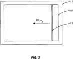
- the excitation light is a line of light 13, i.e., a straight line of light of uniform or substantially uniform intensity, oriented to be perpendicular to the direction of movement of the stage and to span the width of the sample tray.
- the sample stage 11 can be moved by any conventional linear motion drive.
- An example is a lead screw that is driven by a stepper motor or by a DC motor with an encoder to detect the position of the stage as it moves and regulates the movement in a precise manner.
- the stage itself can be mounted on a slide or guide rods with bushings.
- Other examples of the drive and the stage mounting will be readily apparent to those skilled in the art, such as a motorized rack and pinion drive.
- the same types of linear motion drives can be used.
- FIG. 2 is a top view of the sample stage 11, showing the sample area 19 on the surface of the stage.
- the line of light 13 spans the width of the sample area 19, and moves in the direction indicated by the arrow 20 to sweep the full length of the sample area.
- the line of light can be formed by a series of LEDs in a closely spaced linear array.
- the spacing between adjacent LEDs may, for example, be 1 mm or a distance on the order of 1 mm.
- the light emitted by the LEDs can be collimated by a lens and is incident on the stage as a narrow swath of light across the sample.
- the configuration and placement of the LEDs are chosen to produce bright and substantially uniform illumination along the length of the line of light.
- the LEDs are also chosen such that the wavelength band of the line of light is nominally in the desired excitation band for the reporter moieties in the sample.
- an interference optical band pass filter is placed between the line of light and the sample to remove essentially all traces of light that may also be emitted by the LED but are outside the desired excitation band.
- the interference filter allows the light in the desired band to pass by absorbing the light outside the band.
- one set of wavelengths for excitation and emission may be optimal for one label or stain and other sets may be optimal for other labels or stains.
- the instrument can be designed to allow a selection among different wavelengths for excitation and a selection among different emission filters to detect emissions at different wavelengths.
- One means of achieving a selection of wavelengths for excitation is by mounting two or more light sources on a rotating turret 14. The number of wavelengths that can be made available in this manner can vary widely.
- the turret 14 can accommodate five, six, or more light sources producing lines of light of different wavelengths. These embodiments allow the system to assemble images of a sample with multi-colored reporter moieties and to superimpose these images for further data analysis.
- Another means of producing lines of light of different wavelengths is by mounting the light sources on a slide and by moving the slide to place the light with the wavelength of choice for a particular application in position for proper alignment with the sample stage 11.
- An alternative light source is a laser, which can be formed into a line of light by suitable optics whose choice and configuration will be apparent to those skilled in the art. Multiple lasers emitting at different wavelengths can likewise be mounted on a turret. Still other light sources, known to those skilled in the art, that can produce or be formed into a line of light, can be used.
- the turret When the turret is formed with a hollow core, it can be continuously purged with a coolant to remove the heat generated by the light source(s).
- a stream of air for example can serve as the coolant.
- the turret thus acts as an effective heat sink.
- the fluorescent light emitted by the sample as a result of the excitation is collected by a lens 21 which directs the light to the CCD chip of a camera 22 where the light forms an image of the chromatogram or other sample array. Before reaching the detector, however, the emitted light passes through an emission filter 23.
- a motorized filter wheel 24 allows the selection of the appropriate filter for a given excitation light source. The filter also blocks any scattered excitation light.
- the line of excitation light 13 travels over the sample that is supported by the stage, and the CCD camera 22 forms an image of the emitted light.
- Imaging is achieved by conventional means, including the generation of electrons in pixels by the collection of photons from the sample emissions.
- the electrons thus generated are continuously transferred across the CCD from one column of pixels to the next in the direction of travel.
- the rate of clocking of each column of pixels on the CCD is proportional to, and synchronized with, the stage speed, such that once a given point on the sample traverses the line of light, the fluorescence at the point continues to be emitted and focuses on the conjugate pixel elements that continue to generate electrons.
- the generated electrons are transferred between the pixel columns at exactly the same rate.
- the electrons are thus accumulated in the pixel array before the charge is recorded, in a process known as time delay integration. In this manner, the collection of electrons from a sample point is enhanced.
- the invention is particularly useful on samples that emit fluorescence, where the typical excitation wavelengths are nominally 365, 405, 470, 490, 530, 630, 660, and 780 nm. Additional wavelengths can also be used, however, such as those produced by UV LEDs with emissions below 365 nm. As noted above, the presently preferred configuration is one that allows a selection among four different wavelengths.
- the emission filter wheel 24 in the embodiment shown in the figure can accommodate up to six filters to correspond with the emission wavelengths. The selection can be performed automatically. While the filter wheel is in front of the lens 21 in the configuration shown in the figure, the wheel can also be located within the camera between the lens 21 and the CCD chip in the camera 22.
- trans-illumination is used rather than epi-illumination.
- Trans-illumination is achieved in FIG. 1 by a light source 31 positioned below the sample stage.
- This light source like the epi-illumination light source 12, produces a line of light 32, but one that passes through the sample stage 11 from underneath rather than striking the sample stage from above.
- One example of a mode of detection that can effectively make use of trans-illumination is densitometry, using light absorption measurements.
- Non-opaque samples such as Coomassie-stained or silver-stained gels, whose components absorb light in the visible spectrum, are examples of samples suitable for this type of detection.
- Densitometry measurements are performed by placing the light source, which for these embodiments can be a white light source, underneath the sample tray.
- the sample tray can be of a transparent material such as glass or fused silica.
- a white light source is a white LED array; another is a fluorescent white light.
- Alternatives to a white light source are a UV light source and light sources emitting light at any of the wavelengths mentioned above.
- the light source is enclosed and light from the source passes from the enclosure through a slit that is positioned across and underneath the sample tray, and oriented in a direction transverse to the direction of travel of the sample tray.
- the sample tray travels in a linear direction at a precisely controlled rate, and the light that is not absorbed and is within the field of the lens is collected by the lens and imaged onto the detector.
- An emission filter can also be included.
- Instruments in accordance with this invention can also be constructed to perform area CCD imaging for samples that are detected by way of chemiluminescence emission, in addition to the instrument's capability for scanning with a line of light and time delay integration of the signal.
- area imaging which is also referred to as operating in a "full-frame” mode or obtaining a "full-frame” image
- the stage with the sample tray is centered relative to the camera, and the image of the chemiluminescence pattern from the sample is collected by the full area of the CCD and processed accordingly, without illumination of the sample by a light source.
- the filter wheel can have a position that has a clear opening without any filter, to allow the emission light to focus on the CCD as needed.
- the same CCD camera can thus be used both in a moving line mode and a full-frame mode at the selection of the operator.
- the instrument software can itself be programmed to offer the user a choice between the moving line mode and the full-frame mode.
- the moving line mode will generally be used for imaging samples that are not chemiluminescent.
- a single instrument can thus be used to present a choice among multiple imaging platforms such as fluorescence, colorimetry, chemiluminescence, and densitometry, as well as a choice between operating in a moving-line mode and a full-frame mode. Instruments designed to choose between epi-illumination and trans-illumination, or to perform both simultaneously or in succession, are also within the scope of this invention.
- a single instrument can thus produce fluorometric or colorimetric analyses by epi-illumination and fluorometric or densitometric analyses by trans-illumination.
- Processing of the data collected by the CCD and other instrument functions such as selection and control of the light sources are readily performed by computer 33 ( FIG. 1 ) using conventional software used in biotechnology laboratories and known in the art.
- the software can govern the movement of the moving parts of the system and coordinate the moving parts with the time delay integration of the CCD.
- software can be used that overlays and aligns the scans to form a single superimposed image.
- Another way to utilize the apparatus and method of this invention is to first perform a pre-scan to obtain an estimate of the intensities of the signals that are being emitted by the sample. Once these estimates are obtained, operating conditions can be selected that will be optimal for producing an image of the sample. The scan is then repeated with the instrument set at these optimal conditions.
- the operating conditions may include the relative speed of movement between the sample and the detector, the intensity of the light source(s), and the start and stop timing of data collected by the detector.
- the determination of the optimal conditions can be accomplished by automated instrumentation.
- a pre-scan can also be used to locate an area or areas of interest within a sample area, such as areas emitting signals of high intensity relative to adjacent areas, and then performing a second scan on the area(s) of interest only.
- the apparatus and method of this invention are useful in the imaging of a single two-dimensional sample on a sample tray, as well as in the imaging of a series of samples.
- the sample stage 11 can thus be replaced with a moving endless surface such as a conveyor belt on which a large number of samples can be placed. This allows a multitude of samples to be imaged at a high throughput rate, and is particularly susceptible to automation. Samples of varying lengths can also be processed in this manner.
- an apodizing filter can be interposed in the excitation path to enhance the uniformity of the line of light.
- An apodizing filter can also be interposed in the detection path to compensate for lens distortions in the detector and thereby improve the uniformity of the light collected by the CCD.
Landscapes
- Health & Medical Sciences (AREA)
- Chemical & Material Sciences (AREA)
- Physics & Mathematics (AREA)
- Life Sciences & Earth Sciences (AREA)
- General Health & Medical Sciences (AREA)
- General Physics & Mathematics (AREA)
- Pathology (AREA)
- Immunology (AREA)
- Analytical Chemistry (AREA)
- Biochemistry (AREA)
- Molecular Biology (AREA)
- Chemical Kinetics & Catalysis (AREA)
- Nuclear Medicine, Radiotherapy & Molecular Imaging (AREA)
- Spectroscopy & Molecular Physics (AREA)
- Electrochemistry (AREA)
- Engineering & Computer Science (AREA)
- Plasma & Fusion (AREA)
- Investigating, Analyzing Materials By Fluorescence Or Luminescence (AREA)
- Investigating Or Analysing Materials By Optical Means (AREA)
- Investigating Or Analysing Materials By The Use Of Chemical Reactions (AREA)
Claims (15)
- Vorrichtung zur Bildung eines zweidimensionalen Bildes eines zweidimensionalen biologischen Proben-Arrays, wobei die Probe ein Gel, ein Blot oder ein Leuchtschirm ist, wobei die Vorrichtung umfasst:einen Probenhalter (11), der eine planare Probenfläche mit einer Breite und einer Länge definiert;eine Lichtquelle (12), die eine Lichtlinie (13) bildet, welche die Breite der Probenfläche überspannt;Einrichtungen zum Bewegen entweder des Probenhalters (11) oder der Lichtquelle (12) entlang einer Achse parallel zu der Länge des Probenhalters, um dadurch die gesamte Probenfläche der Lichtlinie (13) auszusetzen;einen Detektor, der eine CCD-Kamera (22) im TDI-Modus (TDI: time delay integration) umfasst, wobei der Detektor so angeordnet ist, dass er Licht auffängt, das von der Probenfläche ausgeht, während die Probenfläche von der Lichtlinie (13) beleuchtet wird; undEinrichtungen (33) zum computerisierten Verarbeiten von Daten, die von dem Detektor gesammelt wurden, so dass ein Bild von der Probenfläche zusammengesetzt wird, während die Bewegungseinrichtung die gesamte Probenfläche der Lichtlinie (13) aussetzt.
- Vorrichtung gemäß Anspruch 1, wobei sich die Lichtquelle und der Detektor auf derselben Seite des Probenhalters befinden und dadurch ein Auflicht erzeugen.
- Vorrichtung gemäß Anspruch 1, wobei sich die Lichtquelle und der Detektor auf entgegengesetzten Seiten des Probenhalters befinden und dadurch ein Durchlicht erzeugen.
- Vorrichtung gemäß Anspruch 1, wobei es sich bei der Lichtquelle um einen linearen Array von LEDs handelt, der vorzugsweise mit einem Interferenzbandpassfilter gekoppelt ist, oder die Lichtquelle eine Laserlichtquelle ist, die als Lichtlinie projiziert wird.
- Vorrichtung gemäß Anspruch 1, die weiterhin eine Einrichtung zum Auswählen aus einer Vielzahl von Lichtquellen verschiedener Wellenlängen umfasst, vorzugsweise durch Bandpassfilter.
- Vorrichtung gemäß Anspruch 1, wobei der Detektor weiterhin Einrichtungen zum Auffangen von Fluoreszenzemissionen bei einer Vielzahl von Emissionswellenlängenbanden durch Verwendung von optischen Filtern umfasst und die Einrichtung zum computerisierten Verarbeiten von Daten Einrichtungen zum Übereinanderlegen und Aneinanderausrichten von Daten umfasst, die in einer Vielzahl von Abtastungen erhalten wurden, wobei jede Abtastung Licht an einer der Vielzahl von Wellenlängenbanden auffängt.
- Vorrichtung gemäß Anspruch 1, die weiterhin einen Apodisationsfilter umfasst, der zwischen der Lichtquelle und dem Probenhalter angeordnet ist, um die Gleichmäßigkeit des Lichts entlang der Länge der Lichtlinie zu verbessern.
- Vorrichtung gemäß Anspruch 1, wobei die Einrichtung zum computerisierten Verarbeiten von Daten Einrichtungen zum Auswählen umfasst zwischen (i) dem Zusammensetzen eines Chemilumineszenz-Vollbilds der Probenfläche ohne Beleuchtung der Probenfläche durch die Lichtquelle und (ii) dem Zusammensetzen eines Bildes der Probenfläche, aber nicht durch Chemilumineszenz, während die Einrichtung zum Bewegen die gesamte Probenfläche der Lichtlinie aussetzt.
- Verfahren zur Bildung eines zweidimensionalen Bildes eines zweidimensionalen biologischen Proben-Arrays, wobei die Probe ein Gel, ein Blot oder ein Leuchtschirm ist, wobei das Verfahren umfasst:(a) Platzieren des Proben-Arrays auf einer planaren Probenfläche mit einer Länge und einer Breite in einer Vorrichtung, die Folgendes umfasst: (i) einen Probenhalter (11) mit einer Oberfläche, die die Probenfläche umfasst; (ii) eine Lichtquelle (12), die eine Lichtlinie (13) bildet, welche die Breite der Probenfläche überspannt; und (iii) einen Detektor, der eine CCD-Kamera (22) im TDI-Modus umfasst, die so angeordnet ist, dass sie Licht auffängt, das von der Probenfläche ausgeht, während die Probenfläche von der Lichtlinie beleuchtet wird;(b) Bewegen entweder des Probenhalters oder der Lichtquelle entlang einer Achse parallel zu der Länge des Probenhalters, so dass die gesamte Probenfläche der Lichtlinie ausgesetzt wird; und(c) Verarbeiten von Daten, die von dem Detektor gesammelt wurden, so dass ein zweidimensionales Bild des Proben-Arrays zusammengesetzt wird.
- Verfahren gemäß Anspruch 9, wobei sich die Lichtquelle und der Detektor auf derselben Seite des Probenhalters befinden und dadurch ein Auflicht erzeugen.
- Verfahren gemäß Anspruch 9, wobei sich die Lichtquelle und der Detektor auf entgegengesetzten Seiten des Probenhalters befinden und dadurch ein Durchlicht erzeugen, wobei vorzugsweise die Vorrichtung eine zweite Lichtquelle, die sich auf derselben Seite des Probenhalters wie der Detektor befindet, wobei Auflicht entsteht, wobei das Verfahren das Durchführen von entweder einem oder beiden von (1) fluorometrischem Nachweis, kolorimetrischer Analyse oder sowohl fluorometrischem als auch kolorimetrischem Nachweis durch das Auflicht und (2) fluorometrischen oder densitometrischen Nachweis mittels Durchlicht umfasst.
- Verfahren gemäß Anspruch 9, das weiterhin das Auffangen von Licht durch eine Vielzahl von Abtastungen, wobei jede Abtastung durch Verwendung von optischen Filtern an einer anderen Emissionswellenlängenbande durchgeführt wird, und das Übereinanderlegen und Aneinanderausrichten von Daten, die in der Vielzahl von Abtastungen erhalten wurden, umfasst.
- Verfahren gemäß Anspruch 9, wobei (b) das Bewegen des Probenhalters umfasst, während die Lichtquelle stationär gehalten wird.
- Verfahren gemäß Anspruch 9, wobei (b) das Bewegen der Lichtquelle umfasst, während der Probenhalter stationär gehalten wird.
- Verfahren gemäß Anspruch 9, das weiterhin zuerst das Durchführen der Schritte (a), (b) und (c) zur Bestimmung der optimalen Betriebsparameter zum Zusammensetzen des zweidimensionalen Bildes des Proben-Arrays und dann das Wiederholen der Schritte (a), (b) und (c) unter den so bestimmten optimalen Betriebsparametern umfasst, um das zweidimensionale Bild zusammenzusetzen; oder zuerst das Durchführen der Schritte (a), (b) und (c) zur Lokalisierung eines interessierenden Bereichs in dem Proben-Array, der dadurch definiert ist, dass aus dem interessierenden Bereich ein höheres Signal emittiert wird als aus benachbarten Bereichen, und dann das Wiederholen der Schritte (a), (b) und (c), während die Schritte auf den interessierenden Bereich beschränkt sind, umfasst.
Applications Claiming Priority (3)
| Application Number | Priority Date | Filing Date | Title |
|---|---|---|---|
| US87136906P | 2006-12-21 | 2006-12-21 | |
| US11/956,004 US7692162B2 (en) | 2006-12-21 | 2007-12-13 | Imaging of two-dimensional arrays |
| PCT/US2007/088153 WO2008079881A1 (en) | 2006-12-21 | 2007-12-19 | Imaging of two-dimensional arrays |
Publications (3)
| Publication Number | Publication Date |
|---|---|
| EP2095104A1 EP2095104A1 (de) | 2009-09-02 |
| EP2095104A4 EP2095104A4 (de) | 2010-03-10 |
| EP2095104B1 true EP2095104B1 (de) | 2019-03-20 |
Family
ID=39541502
Family Applications (1)
| Application Number | Title | Priority Date | Filing Date |
|---|---|---|---|
| EP07865871.3A Not-in-force EP2095104B1 (de) | 2006-12-21 | 2007-12-19 | Abbildung zweidimensionaler arrays |
Country Status (6)
| Country | Link |
|---|---|
| US (1) | US7692162B2 (de) |
| EP (1) | EP2095104B1 (de) |
| JP (1) | JP5174035B2 (de) |
| CA (1) | CA2672635C (de) |
| DE (1) | DE07865871T1 (de) |
| WO (1) | WO2008079881A1 (de) |
Families Citing this family (17)
| Publication number | Priority date | Publication date | Assignee | Title |
|---|---|---|---|---|
| JP5792472B2 (ja) | 2011-01-25 | 2015-10-14 | 浜松ホトニクス株式会社 | 放射線画像取得装置 |
| CA2837988A1 (en) * | 2011-06-06 | 2012-12-13 | Sicpa Holding Sa | In-line decay-time scanner |
| US20140002608A1 (en) * | 2011-12-28 | 2014-01-02 | Faro Technologies, Inc. | Line scanner using a low coherence light source |
| US8985808B2 (en) * | 2012-02-29 | 2015-03-24 | Bio-Rad Laboratories, Inc. | Uniform epi-illumination of planar samples |
| JP5690359B2 (ja) * | 2012-03-30 | 2015-03-25 | 株式会社Screenホールディングス | 撮像装置および撮像方法 |
| JP5944254B2 (ja) | 2012-07-20 | 2016-07-05 | 浜松ホトニクス株式会社 | 放射線画像取得装置 |
| US9291564B2 (en) * | 2013-04-05 | 2016-03-22 | Datacolor Holding Ag | Method and apparatus for aligning measured spectral radiance factors among different instruments |
| CN105143856B (zh) | 2013-04-24 | 2019-06-18 | 欧蒙医学诊断技术有限公司 | 用于自动化评估孵育的免疫印迹条的方法 |
| DE102013008468A1 (de) * | 2013-05-21 | 2014-11-27 | Euroimmun Medizinische Labordiagnostika Ag | Verfahren zur automatisierten Auswertung von inkubierten lmmunoblotstreifen |
| CN103409317B (zh) * | 2013-07-23 | 2015-04-22 | 广州市第一人民医院 | 一种毛细管生物分析系统及其分析方法与应用 |
| EP2986957B1 (de) * | 2014-05-01 | 2021-09-29 | Bio-Rad Laboratories, Inc. | Abbildungsanordnung für emissionslicht |
| US10859715B2 (en) * | 2015-09-30 | 2020-12-08 | Hamamatsu Photonics K.K. | Radiation image acquisition system and radiation image acquisition method |
| CN105806991A (zh) * | 2016-03-25 | 2016-07-27 | 苏州市合叶精密机械有限公司 | 一种普适性强的紫外薄层色谱拍照仪 |
| CN105806990A (zh) * | 2016-03-25 | 2016-07-27 | 苏州市合叶精密机械有限公司 | 一种便于观看的紫外薄层色谱拍照仪 |
| GB2581363A (en) * | 2019-02-14 | 2020-08-19 | Univ Exeter | Test apparatus |
| JP2024501232A (ja) * | 2020-12-21 | 2024-01-11 | シンギュラー・ゲノミクス・システムズ・インコーポレイテッド | 多色撮像のためのシステム及び方法 |
| US20230086701A1 (en) * | 2021-09-17 | 2023-03-23 | Bio-Rad Laboratories, Inc. | System for cumulative imaging of biological samples |
Citations (3)
| Publication number | Priority date | Publication date | Assignee | Title |
|---|---|---|---|---|
| EP0711995A2 (de) * | 1994-11-14 | 1996-05-15 | Eastman Kodak Company | Als linearer Integrations-Hohlraum ausgebildete Lichtquelle zur Infrarot-Beleuchtung sensibilisierter Materialien |
| EP0738886A2 (de) * | 1995-04-20 | 1996-10-23 | Eastman Kodak Company | Schichtdichte Analysator und Verfahren zur Verwendung von nicht synchronen TDI Kameras |
| US20020066866A1 (en) * | 2000-12-04 | 2002-06-06 | Fuji Photo Film Co., Ltd. | Image reading method and apparatus |
Family Cites Families (18)
| Publication number | Priority date | Publication date | Assignee | Title |
|---|---|---|---|---|
| US4960999A (en) | 1989-02-13 | 1990-10-02 | Kms Fusion, Inc. | Scanning and storage of electrophoretic records |
| US5141609A (en) | 1990-11-16 | 1992-08-25 | The Trustees Of The Leland Stanford Junior University | Method and device employing time-delayed integration for detecting sample components after separation |
| US5754291A (en) * | 1996-09-19 | 1998-05-19 | Molecular Dynamics, Inc. | Micro-imaging system |
| US6649416B1 (en) * | 2000-02-18 | 2003-11-18 | Trustees Of Tufts College | Intelligent electro-optical sensor array and method for analyte detection |
| US6512577B1 (en) * | 2000-03-13 | 2003-01-28 | Richard M. Ozanich | Apparatus and method for measuring and correlating characteristics of fruit with visible/near infra-red spectrum |
| US20030160957A1 (en) * | 2000-07-14 | 2003-08-28 | Applera Corporation | Scanning system and method for scanning a plurality of samples |
| EP1342079B1 (de) | 2000-11-13 | 2010-03-03 | Sonoscan, Inc. | Verarbeitung von akustischen mikroabbildungssignalen im frequenzbereich |
| US20030039383A1 (en) * | 2001-06-26 | 2003-02-27 | Bio-Rad Laboratories, Inc. | Flat field correction of two-dimensional biochemical assay images |
| US7265833B2 (en) | 2001-07-25 | 2007-09-04 | Applera Corporation | Electrophoretic system with multi-notch filter and laser excitation source |
| WO2003010524A1 (en) | 2001-07-25 | 2003-02-06 | Applera Corporation | Time-delay integration in electrophoretic detection systems |
| WO2003014400A1 (en) | 2001-08-08 | 2003-02-20 | Applied Precision, Llc | Time-delay integration imaging of biological specimens |
| EP2302363A2 (de) | 2001-09-05 | 2011-03-30 | Life Technologies Corporation | Verfahren zur Normalisierung von Analysedaten |
| US20040197793A1 (en) | 2002-08-30 | 2004-10-07 | Arjang Hassibi | Methods and apparatus for biomolecule detection, identification, quantification and/or sequencing |
| AU2003900924A0 (en) * | 2003-02-28 | 2003-03-13 | Medsaic Pty Ltd | Imaging device |
| JP2004271444A (ja) | 2003-03-11 | 2004-09-30 | Toshiba Corp | 検査方法、検査装置およびマスク欠陥検査方法 |
| US7002688B2 (en) * | 2003-10-16 | 2006-02-21 | Pria Diagnostics, Inc. | Multilens optical assembly for a diagnostic device |
| US7315358B2 (en) * | 2004-06-30 | 2008-01-01 | Olympus Corporation | Evaluation apparatus and method of optical parts |
| JP4616051B2 (ja) | 2005-04-05 | 2011-01-19 | 株式会社日立ハイテクノロジーズ | 電気泳動装置、及び電気泳動方法 |
-
2007
- 2007-12-13 US US11/956,004 patent/US7692162B2/en active Active
- 2007-12-19 CA CA2672635A patent/CA2672635C/en not_active Expired - Fee Related
- 2007-12-19 JP JP2009543187A patent/JP5174035B2/ja not_active Expired - Fee Related
- 2007-12-19 EP EP07865871.3A patent/EP2095104B1/de not_active Not-in-force
- 2007-12-19 DE DE07865871T patent/DE07865871T1/de active Pending
- 2007-12-19 WO PCT/US2007/088153 patent/WO2008079881A1/en active Application Filing
Patent Citations (3)
| Publication number | Priority date | Publication date | Assignee | Title |
|---|---|---|---|---|
| EP0711995A2 (de) * | 1994-11-14 | 1996-05-15 | Eastman Kodak Company | Als linearer Integrations-Hohlraum ausgebildete Lichtquelle zur Infrarot-Beleuchtung sensibilisierter Materialien |
| EP0738886A2 (de) * | 1995-04-20 | 1996-10-23 | Eastman Kodak Company | Schichtdichte Analysator und Verfahren zur Verwendung von nicht synchronen TDI Kameras |
| US20020066866A1 (en) * | 2000-12-04 | 2002-06-06 | Fuji Photo Film Co., Ltd. | Image reading method and apparatus |
Non-Patent Citations (1)
| Title |
|---|
| HOLDSWORTH D W ET AL: "A TIME-DELAY INTEGRATION CHARGE-COUPLED DEVICE CAMERA FOR SLOT-SCANNED DIGITAL RADIOGRAPHY", MEDICAL PHYSICS, AIP, MELVILLE, NY, US, vol. 17, no. 5, 1 September 1990 (1990-09-01), pages 876 - 886, XP000170781, ISSN: 0094-2405, ISBN: 978-1-930524-56-9, DOI: 10.1118/1.596578 * |
Also Published As
| Publication number | Publication date |
|---|---|
| DE07865871T1 (de) | 2010-01-07 |
| CA2672635A1 (en) | 2008-07-03 |
| EP2095104A1 (de) | 2009-09-02 |
| JP5174035B2 (ja) | 2013-04-03 |
| US20080149855A1 (en) | 2008-06-26 |
| WO2008079881A1 (en) | 2008-07-03 |
| JP2010515019A (ja) | 2010-05-06 |
| EP2095104A4 (de) | 2010-03-10 |
| CA2672635C (en) | 2016-02-09 |
| US7692162B2 (en) | 2010-04-06 |
Similar Documents
| Publication | Publication Date | Title |
|---|---|---|
| EP2095104B1 (de) | Abbildung zweidimensionaler arrays | |
| JP3626951B2 (ja) | 複数のサンプルを走査する走査システムおよび走査方法 | |
| EP1055925A2 (de) | Biochip-Lesegerät und Elektrophoresesystem | |
| JP2010515019A5 (de) | ||
| US6856390B2 (en) | Time-delay integration in electrophoretic detection systems | |
| DE102006058575B4 (de) | Multiplex-CE-Fluoreszenzsystem | |
| EP0488422B1 (de) | Vorrichtung zur Auswertung fluoreszenzmarkierter Gelelektrophoresemuster | |
| US5556529A (en) | DNA base sequencer | |
| JPH0310147A (ja) | 蛍光式電気泳動パターン読み取り装置 | |
| US7532326B2 (en) | Multiple-label fluorescence imaging using excitation-emission matrices | |
| US7118659B2 (en) | Robotic friendly external loading system for electrophoresis instrument and method | |
| US6833919B2 (en) | Multiplexed, absorbance-based capillary electrophoresis system and method | |
| CA2284195A1 (en) | Device and method for capillary electrophoresis | |
| US20230221178A1 (en) | Apparatus and a method for fluorescence imaging | |
| US7277176B2 (en) | Emission filter X-Y array | |
| JP2000151916A (ja) | 画像情報読取装置 | |
| JP2006105881A (ja) | 電気泳動装置 | |
| JPH0814537B2 (ja) | Dna配列決定のための実時間走査電気泳動装置 | |
| JP2002072393A (ja) | 画像読み取り装置 | |
| AU2001273686A1 (en) | Scanning system and method for scanning a plurality of samples |
Legal Events
| Date | Code | Title | Description |
|---|---|---|---|
| PUAI | Public reference made under article 153(3) epc to a published international application that has entered the european phase |
Free format text: ORIGINAL CODE: 0009012 |
|
| 17P | Request for examination filed |
Effective date: 20090618 |
|
| AK | Designated contracting states |
Kind code of ref document: A1 Designated state(s): AT BE BG CH CY CZ DE DK EE ES FI FR GB GR HU IE IS IT LI LT LU LV MC MT NL PL PT RO SE SI SK TR |
|
| EL | Fr: translation of claims filed | ||
| DET | De: translation of patent claims | ||
| A4 | Supplementary search report drawn up and despatched |
Effective date: 20100209 |
|
| RIC1 | Information provided on ipc code assigned before grant |
Ipc: G01N 27/447 20060101ALI20100203BHEP Ipc: G01N 30/95 20060101AFI20100203BHEP |
|
| DAX | Request for extension of the european patent (deleted) | ||
| 17Q | First examination report despatched |
Effective date: 20100510 |
|
| STAA | Information on the status of an ep patent application or granted ep patent |
Free format text: STATUS: EXAMINATION IS IN PROGRESS |
|
| GRAP | Despatch of communication of intention to grant a patent |
Free format text: ORIGINAL CODE: EPIDOSNIGR1 |
|
| STAA | Information on the status of an ep patent application or granted ep patent |
Free format text: STATUS: GRANT OF PATENT IS INTENDED |
|
| INTG | Intention to grant announced |
Effective date: 20180927 |
|
| RIN1 | Information on inventor provided before grant (corrected) |
Inventor name: MCDONALD, KEVIN A. Inventor name: MEHTA, SURESH, N. Inventor name: BHATT, NEERAJ |
|
| GRAS | Grant fee paid |
Free format text: ORIGINAL CODE: EPIDOSNIGR3 |
|
| GRAA | (expected) grant |
Free format text: ORIGINAL CODE: 0009210 |
|
| STAA | Information on the status of an ep patent application or granted ep patent |
Free format text: STATUS: THE PATENT HAS BEEN GRANTED |
|
| AK | Designated contracting states |
Kind code of ref document: B1 Designated state(s): AT BE BG CH CY CZ DE DK EE ES FI FR GB GR HU IE IS IT LI LT LU LV MC MT NL PL PT RO SE SI SK TR |
|
| REG | Reference to a national code |
Ref country code: GB Ref legal event code: FG4D |
|
| REG | Reference to a national code |
Ref country code: CH Ref legal event code: EP |
|
| REG | Reference to a national code |
Ref country code: DE Ref legal event code: R096 Ref document number: 602007057927 Country of ref document: DE |
|
| REG | Reference to a national code |
Ref country code: AT Ref legal event code: REF Ref document number: 1111063 Country of ref document: AT Kind code of ref document: T Effective date: 20190415 |
|
| REG | Reference to a national code |
Ref country code: IE Ref legal event code: FG4D |
|
| REG | Reference to a national code |
Ref country code: NL Ref legal event code: MP Effective date: 20190320 |
|
| PG25 | Lapsed in a contracting state [announced via postgrant information from national office to epo] |
Ref country code: LT Free format text: LAPSE BECAUSE OF FAILURE TO SUBMIT A TRANSLATION OF THE DESCRIPTION OR TO PAY THE FEE WITHIN THE PRESCRIBED TIME-LIMIT Effective date: 20190320 Ref country code: SE Free format text: LAPSE BECAUSE OF FAILURE TO SUBMIT A TRANSLATION OF THE DESCRIPTION OR TO PAY THE FEE WITHIN THE PRESCRIBED TIME-LIMIT Effective date: 20190320 Ref country code: FI Free format text: LAPSE BECAUSE OF FAILURE TO SUBMIT A TRANSLATION OF THE DESCRIPTION OR TO PAY THE FEE WITHIN THE PRESCRIBED TIME-LIMIT Effective date: 20190320 |
|
| REG | Reference to a national code |
Ref country code: LT Ref legal event code: MG4D |
|
| PG25 | Lapsed in a contracting state [announced via postgrant information from national office to epo] |
Ref country code: NL Free format text: LAPSE BECAUSE OF FAILURE TO SUBMIT A TRANSLATION OF THE DESCRIPTION OR TO PAY THE FEE WITHIN THE PRESCRIBED TIME-LIMIT Effective date: 20190320 Ref country code: BG Free format text: LAPSE BECAUSE OF FAILURE TO SUBMIT A TRANSLATION OF THE DESCRIPTION OR TO PAY THE FEE WITHIN THE PRESCRIBED TIME-LIMIT Effective date: 20190620 Ref country code: LV Free format text: LAPSE BECAUSE OF FAILURE TO SUBMIT A TRANSLATION OF THE DESCRIPTION OR TO PAY THE FEE WITHIN THE PRESCRIBED TIME-LIMIT Effective date: 20190320 Ref country code: GR Free format text: LAPSE BECAUSE OF FAILURE TO SUBMIT A TRANSLATION OF THE DESCRIPTION OR TO PAY THE FEE WITHIN THE PRESCRIBED TIME-LIMIT Effective date: 20190621 |
|
| REG | Reference to a national code |
Ref country code: AT Ref legal event code: MK05 Ref document number: 1111063 Country of ref document: AT Kind code of ref document: T Effective date: 20190320 |
|
| PG25 | Lapsed in a contracting state [announced via postgrant information from national office to epo] |
Ref country code: EE Free format text: LAPSE BECAUSE OF FAILURE TO SUBMIT A TRANSLATION OF THE DESCRIPTION OR TO PAY THE FEE WITHIN THE PRESCRIBED TIME-LIMIT Effective date: 20190320 Ref country code: IT Free format text: LAPSE BECAUSE OF FAILURE TO SUBMIT A TRANSLATION OF THE DESCRIPTION OR TO PAY THE FEE WITHIN THE PRESCRIBED TIME-LIMIT Effective date: 20190320 Ref country code: SK Free format text: LAPSE BECAUSE OF FAILURE TO SUBMIT A TRANSLATION OF THE DESCRIPTION OR TO PAY THE FEE WITHIN THE PRESCRIBED TIME-LIMIT Effective date: 20190320 Ref country code: ES Free format text: LAPSE BECAUSE OF FAILURE TO SUBMIT A TRANSLATION OF THE DESCRIPTION OR TO PAY THE FEE WITHIN THE PRESCRIBED TIME-LIMIT Effective date: 20190320 Ref country code: PT Free format text: LAPSE BECAUSE OF FAILURE TO SUBMIT A TRANSLATION OF THE DESCRIPTION OR TO PAY THE FEE WITHIN THE PRESCRIBED TIME-LIMIT Effective date: 20190720 Ref country code: CZ Free format text: LAPSE BECAUSE OF FAILURE TO SUBMIT A TRANSLATION OF THE DESCRIPTION OR TO PAY THE FEE WITHIN THE PRESCRIBED TIME-LIMIT Effective date: 20190320 Ref country code: RO Free format text: LAPSE BECAUSE OF FAILURE TO SUBMIT A TRANSLATION OF THE DESCRIPTION OR TO PAY THE FEE WITHIN THE PRESCRIBED TIME-LIMIT Effective date: 20190320 |
|
| PG25 | Lapsed in a contracting state [announced via postgrant information from national office to epo] |
Ref country code: PL Free format text: LAPSE BECAUSE OF FAILURE TO SUBMIT A TRANSLATION OF THE DESCRIPTION OR TO PAY THE FEE WITHIN THE PRESCRIBED TIME-LIMIT Effective date: 20190320 |
|
| PG25 | Lapsed in a contracting state [announced via postgrant information from national office to epo] |
Ref country code: AT Free format text: LAPSE BECAUSE OF FAILURE TO SUBMIT A TRANSLATION OF THE DESCRIPTION OR TO PAY THE FEE WITHIN THE PRESCRIBED TIME-LIMIT Effective date: 20190320 Ref country code: IS Free format text: LAPSE BECAUSE OF FAILURE TO SUBMIT A TRANSLATION OF THE DESCRIPTION OR TO PAY THE FEE WITHIN THE PRESCRIBED TIME-LIMIT Effective date: 20190720 |
|
| REG | Reference to a national code |
Ref country code: DE Ref legal event code: R097 Ref document number: 602007057927 Country of ref document: DE |
|
| PLBE | No opposition filed within time limit |
Free format text: ORIGINAL CODE: 0009261 |
|
| STAA | Information on the status of an ep patent application or granted ep patent |
Free format text: STATUS: NO OPPOSITION FILED WITHIN TIME LIMIT |
|
| PG25 | Lapsed in a contracting state [announced via postgrant information from national office to epo] |
Ref country code: DK Free format text: LAPSE BECAUSE OF FAILURE TO SUBMIT A TRANSLATION OF THE DESCRIPTION OR TO PAY THE FEE WITHIN THE PRESCRIBED TIME-LIMIT Effective date: 20190320 |
|
| 26N | No opposition filed |
Effective date: 20200102 |
|
| PG25 | Lapsed in a contracting state [announced via postgrant information from national office to epo] |
Ref country code: SI Free format text: LAPSE BECAUSE OF FAILURE TO SUBMIT A TRANSLATION OF THE DESCRIPTION OR TO PAY THE FEE WITHIN THE PRESCRIBED TIME-LIMIT Effective date: 20190320 |
|
| PG25 | Lapsed in a contracting state [announced via postgrant information from national office to epo] |
Ref country code: TR Free format text: LAPSE BECAUSE OF FAILURE TO SUBMIT A TRANSLATION OF THE DESCRIPTION OR TO PAY THE FEE WITHIN THE PRESCRIBED TIME-LIMIT Effective date: 20190320 |
|
| REG | Reference to a national code |
Ref country code: CH Ref legal event code: PL |
|
| REG | Reference to a national code |
Ref country code: BE Ref legal event code: MM Effective date: 20191231 |
|
| PG25 | Lapsed in a contracting state [announced via postgrant information from national office to epo] |
Ref country code: MC Free format text: LAPSE BECAUSE OF FAILURE TO SUBMIT A TRANSLATION OF THE DESCRIPTION OR TO PAY THE FEE WITHIN THE PRESCRIBED TIME-LIMIT Effective date: 20190320 |
|
| PG25 | Lapsed in a contracting state [announced via postgrant information from national office to epo] |
Ref country code: IE Free format text: LAPSE BECAUSE OF NON-PAYMENT OF DUE FEES Effective date: 20191219 Ref country code: LU Free format text: LAPSE BECAUSE OF NON-PAYMENT OF DUE FEES Effective date: 20191219 |
|
| PG25 | Lapsed in a contracting state [announced via postgrant information from national office to epo] |
Ref country code: BE Free format text: LAPSE BECAUSE OF NON-PAYMENT OF DUE FEES Effective date: 20191231 Ref country code: LI Free format text: LAPSE BECAUSE OF NON-PAYMENT OF DUE FEES Effective date: 20191231 Ref country code: CH Free format text: LAPSE BECAUSE OF NON-PAYMENT OF DUE FEES Effective date: 20191231 |
|
| PGFP | Annual fee paid to national office [announced via postgrant information from national office to epo] |
Ref country code: FR Payment date: 20201229 Year of fee payment: 14 Ref country code: GB Payment date: 20201228 Year of fee payment: 14 |
|
| PG25 | Lapsed in a contracting state [announced via postgrant information from national office to epo] |
Ref country code: CY Free format text: LAPSE BECAUSE OF FAILURE TO SUBMIT A TRANSLATION OF THE DESCRIPTION OR TO PAY THE FEE WITHIN THE PRESCRIBED TIME-LIMIT Effective date: 20190320 |
|
| PGFP | Annual fee paid to national office [announced via postgrant information from national office to epo] |
Ref country code: DE Payment date: 20210224 Year of fee payment: 14 |
|
| PG25 | Lapsed in a contracting state [announced via postgrant information from national office to epo] |
Ref country code: HU Free format text: LAPSE BECAUSE OF FAILURE TO SUBMIT A TRANSLATION OF THE DESCRIPTION OR TO PAY THE FEE WITHIN THE PRESCRIBED TIME-LIMIT; INVALID AB INITIO Effective date: 20071219 Ref country code: MT Free format text: LAPSE BECAUSE OF FAILURE TO SUBMIT A TRANSLATION OF THE DESCRIPTION OR TO PAY THE FEE WITHIN THE PRESCRIBED TIME-LIMIT Effective date: 20190320 |
|
| REG | Reference to a national code |
Ref country code: DE Ref legal event code: R119 Ref document number: 602007057927 Country of ref document: DE |
|
| GBPC | Gb: european patent ceased through non-payment of renewal fee |
Effective date: 20211219 |
|
| PG25 | Lapsed in a contracting state [announced via postgrant information from national office to epo] |
Ref country code: GB Free format text: LAPSE BECAUSE OF NON-PAYMENT OF DUE FEES Effective date: 20211219 Ref country code: DE Free format text: LAPSE BECAUSE OF NON-PAYMENT OF DUE FEES Effective date: 20220701 |
|
| PG25 | Lapsed in a contracting state [announced via postgrant information from national office to epo] |
Ref country code: FR Free format text: LAPSE BECAUSE OF NON-PAYMENT OF DUE FEES Effective date: 20211231 |
|
| P01 | Opt-out of the competence of the unified patent court (upc) registered |
Free format text: CASE NUMBER: UPC_APP_118851/2023 Effective date: 20230510 |