EP2094550B1 - Frein pourvu d'un matériau répondant au champ magnétique - Google Patents
Frein pourvu d'un matériau répondant au champ magnétique Download PDFInfo
- Publication number
- EP2094550B1 EP2094550B1 EP07865968.7A EP07865968A EP2094550B1 EP 2094550 B1 EP2094550 B1 EP 2094550B1 EP 07865968 A EP07865968 A EP 07865968A EP 2094550 B1 EP2094550 B1 EP 2094550B1
- Authority
- EP
- European Patent Office
- Prior art keywords
- controllable
- controllable brake
- magnetic
- sensor
- magnetic field
- Prior art date
- Legal status (The legal status is an assumption and is not a legal conclusion. Google has not performed a legal analysis and makes no representation as to the accuracy of the status listed.)
- Active
Links
- 239000000463 material Substances 0.000 title claims description 29
- 230000005355 Hall effect Effects 0.000 claims description 19
- 230000004907 flux Effects 0.000 claims description 6
- 238000012544 monitoring process Methods 0.000 claims description 3
- 238000000518 rheometry Methods 0.000 claims description 3
- 239000004065 semiconductor Substances 0.000 description 21
- XUIMIQQOPSSXEZ-UHFFFAOYSA-N Silicon Chemical compound [Si] XUIMIQQOPSSXEZ-UHFFFAOYSA-N 0.000 description 6
- 229910052710 silicon Inorganic materials 0.000 description 6
- 239000010703 silicon Substances 0.000 description 6
- 230000007613 environmental effect Effects 0.000 description 3
- CWYNVVGOOAEACU-UHFFFAOYSA-N Fe2+ Chemical compound [Fe+2] CWYNVVGOOAEACU-UHFFFAOYSA-N 0.000 description 2
- 230000003750 conditioning effect Effects 0.000 description 2
- 239000000314 lubricant Substances 0.000 description 2
- 239000002245 particle Substances 0.000 description 2
- 238000001914 filtration Methods 0.000 description 1
- 229910052751 metal Inorganic materials 0.000 description 1
- 239000002184 metal Substances 0.000 description 1
- CWQXQMHSOZUFJS-UHFFFAOYSA-N molybdenum disulfide Chemical compound S=[Mo]=S CWQXQMHSOZUFJS-UHFFFAOYSA-N 0.000 description 1
- 229910052982 molybdenum disulfide Inorganic materials 0.000 description 1
- 238000007789 sealing Methods 0.000 description 1
- 230000026676 system process Effects 0.000 description 1
Images


Classifications
-
- B—PERFORMING OPERATIONS; TRANSPORTING
- B60—VEHICLES IN GENERAL
- B60T—VEHICLE BRAKE CONTROL SYSTEMS OR PARTS THEREOF; BRAKE CONTROL SYSTEMS OR PARTS THEREOF, IN GENERAL; ARRANGEMENT OF BRAKING ELEMENTS ON VEHICLES IN GENERAL; PORTABLE DEVICES FOR PREVENTING UNWANTED MOVEMENT OF VEHICLES; VEHICLE MODIFICATIONS TO FACILITATE COOLING OF BRAKES
- B60T17/00—Component parts, details, or accessories of power brake systems not covered by groups B60T8/00, B60T13/00 or B60T15/00, or presenting other characteristic features
- B60T17/18—Safety devices; Monitoring
- B60T17/22—Devices for monitoring or checking brake systems; Signal devices
-
- B—PERFORMING OPERATIONS; TRANSPORTING
- B60—VEHICLES IN GENERAL
- B60T—VEHICLE BRAKE CONTROL SYSTEMS OR PARTS THEREOF; BRAKE CONTROL SYSTEMS OR PARTS THEREOF, IN GENERAL; ARRANGEMENT OF BRAKING ELEMENTS ON VEHICLES IN GENERAL; PORTABLE DEVICES FOR PREVENTING UNWANTED MOVEMENT OF VEHICLES; VEHICLE MODIFICATIONS TO FACILITATE COOLING OF BRAKES
- B60T13/00—Transmitting braking action from initiating means to ultimate brake actuator with power assistance or drive; Brake systems incorporating such transmitting means, e.g. air-pressure brake systems
- B60T13/74—Transmitting braking action from initiating means to ultimate brake actuator with power assistance or drive; Brake systems incorporating such transmitting means, e.g. air-pressure brake systems with electrical assistance or drive
- B60T13/748—Transmitting braking action from initiating means to ultimate brake actuator with power assistance or drive; Brake systems incorporating such transmitting means, e.g. air-pressure brake systems with electrical assistance or drive acting on electro-magnetic brakes
-
- F—MECHANICAL ENGINEERING; LIGHTING; HEATING; WEAPONS; BLASTING
- F16—ENGINEERING ELEMENTS AND UNITS; GENERAL MEASURES FOR PRODUCING AND MAINTAINING EFFECTIVE FUNCTIONING OF MACHINES OR INSTALLATIONS; THERMAL INSULATION IN GENERAL
- F16D—COUPLINGS FOR TRANSMITTING ROTATION; CLUTCHES; BRAKES
- F16D57/00—Liquid-resistance brakes; Brakes using the internal friction of fluids or fluid-like media, e.g. powders
- F16D57/002—Liquid-resistance brakes; Brakes using the internal friction of fluids or fluid-like media, e.g. powders comprising a medium with electrically or magnetically controlled internal friction, e.g. electrorheological fluid, magnetic powder
Definitions
- the invention relates to the field of motion control devices.
- the invention relates to the field of controllable brakes. More Particularly the invention relates to the field of controllable brakes with magnetic field responsive materials.
- the invention includes a controllable brake as claimed in claim 1.
- the controllable brake preferably includes a magnetically permeable rotor.
- the controllable brake preferably includes a shaft connected to the magnetically permeable rotor.
- the controllable brake preferably includes a housing having a first housing chamber rotatably housing the magnetically permeable rotor therein, and including a magnetic field generator spaced from the magnetically permeable rotor, and configured and positioned for generating a controllable magnetic field to control a relative motion of the magnetically permeable rotor, and a second housing chamber containing control electronics therein, the second housing chamber electronics including at least a first oriented electronic noncontacting magnetic sensor, the at least first oriented electronic noncontacting magnetic sensor oriented relative to the rotating magnetic target and the shaft wherein the at least first oriented electronic noncontacting magnetic sensor monitors the rotation of the rotating magnetic target.
- the invention includes a controllable brake.
- the controllable brake preferably includes a housing including a first chamber and a second chamber.
- the controllable brake preferably includes a shaft, the shaft extending through the first chamber and the second chamber with an axis of rotation, the shaft having a first shaft end.
- the controllable brake preferably includes a controllable brake rotor made integral with the shaft, the rotor housed in the first chamber, with the rotor having a rotation plane preferably normal to the axis of rotation.
- the controllable brake preferably includes a controllable brake magnetic field generator located in the first chamber proximate the controllable brake rotor, the controllable brake magnetic field generator for generating a controllable magnetic field strength.
- the controllable brake preferably includes a controllable brake rotating magnetic target integrated with the shaft proximate the first shaft end, the controllable brake rotating magnetic target housed in the second chamber.
- the controllable brake preferably includes a controllable brake electronics circuit board mounted in the second chamber, the controllable brake electronics circuit board having a control board plane, the control board plane oriented normal to the shaft axis of rotation.
- the controllable brake preferably includes a first electronic noncontacting magnetic sensor having a first sensor plane, the first electronic noncontacting magnetic sensor integrated on the controllable brake electronics circuit board with the first sensor plane parallel with the control board plane.
- the controllable brake preferably includes a second electronic noncontacting magnetic sensor having a second sensor plane, the second electronic noncontacting magnetic sensor integrated on the controllable brake electronics circuit board with the second sensor plane parallel with the control board plane with the control board plane between the first sensor plane and the second sensor plane, the first electronic noncontacting magnetic sensor and the second electronic noncontacting magnetic sensor monitoring the rotation of the controllable brake rotating magnetic target and outputting a rotational position of the controllable brake rotating magnetic target wherein the controllable magnetic field strength generated by the controllable brake magnetic field generator is determined by the rotational position to control a relative motion of the controllable brake rotor.
- the electronic noncontacting magnetic sensors preferably comprise integrated circuit semiconductor sensor chips with at least two positional outputs.
- the electronic noncontacting magnetic sensor integrated circuit semiconductor sensor chip has at least two dies.
- the at least two dies are ASICs (Application Specific Integrated Circuits).
- the at least two dies are side by side dies in the integrated circuit semiconductor sensor chip.
- the at least two dies are vertically stacked dies in the integrated circuit semiconductor sensor chip.
- the integrated circuit semiconductor sensor chip ASIC die include a magnetoresistive material, preferably with electrical resistance changes in the presence of the magnetic target magnetic field, preferably with magnetoresistive elements arranged in a Wheatstone bridge.
- the integrated circuit semiconductor sensor chip ASIC die include a Hall Effect element, preferably a plurality of oriented Hall Effect elements, preferably silicon semiconductor Hall effect elements which detect the magnetic target magnetic field.
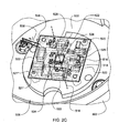
- the controllable brake 500 preferably includes a housing 502.
- the housing 502 preferably includes a first sealed chamber 504 and a second sealed chamber 506.
- the controllable brake preferably includes a shaft 512 with an axis of rotation 516 and a first shaft end 514.
- the shaft extends through the first sealed chamber and the second sealed chamber.
- the controllable brake 500 preferably includes a controllable brake rotor 508 made integral with the shaft, with the rotor 508 housed in the first sealed chamber 504, with the rotor 508 having a rotation plane 570 preferably normal to the axis of rotation 516.
- the controllable brake 500 preferably includes a controllable brake magnetic field generator 510 located in the first chamber proximate the controllable brake rotor 508, the controllable brake magnetic field generator for generating a controllable magnetic field strength.
- the controllable brake preferably includes a controllable brake rotating magnetic target 518 made integral with the shaft proximate the first shaft end 514 with the controllable brake rotating magnetic target 518 housed in the second sealed chamber, and a controllable brake electronics circuit board 520 mounted in the second sealed chamber.
- the brake operation electronics control board 520 controls and/or monitors the operation of the controllable brake 500.
- the magnetic target 518 is at the end of the shaft, preferably with the magnetic target 518 comprised of a magnet with north and south poles oriented relative and normal to the shaft axis of rotation 516 with the opposed N and S poles separated by the axis of rotation 516.
- the field responsive controllable material 532 is comprised of magnetic metal ferrous particles and lubricant, preferably dry ferrous particles and dry lubricant (preferably dry molybdenum disulfide).
- the controllable brake rotating magnetic target 518 is a permanent magnet with a north pole (N) and a south pole (S) opposed along a north south axis 534, with the north south axis 534 perpendicular with the shaft axis of rotation 516.
- controllable brake 500 includes field responsive controllable material 532 sealed in the first chamber 504, with the field responsive controllable material 532 being affected by the controllable magnetic field strength, and the magnetic field generator 510 is adapted to generate a magnetic flux in a direction through the field responsive controllable material 532 towards the rotor 508, and the controllable brake electronics circuit board 520 provides a controlled current to the magnetic field generator 510.
- controllable brake 500 includes a field responsive controllable material 532 sealed in the first chamber 504 with a rheology of the field responsive controllable material 532 being affected by the controllable magnetic field strength, and the magnetic field generator 510 is adapted to generate a magnetic flux 536 in a direction through the field responsive controllable material 532 towards the rotor 508, and the controllable brake electronics circuit board 520 provides a controlled current 538 to the magnetic field generator 510.
- the magnetic field generator 510 includes an electromagnetic coil 546 and the controllable brake electronics circuit board 520 is electrically connected with the magnetic field generator electromagnetic coil 546, preferably with electrical contact connections leads 548 to the EM coil 546.
- the electronics circuit board 520 provides a current 538 (i) to EM coil 546, for applying magnetic field flux 536 whose strength is determined by the rotational position of the rotor 508, with the magnetic target 518 rotation angle sensed by the sensors 524, 528.
- at least one of the electronic noncontacting magnetic sensors 524,528 include a magnetoresistive material, preferably with electrical resistance changes in the presence of the magnetic target 518 magnetic field, preferably with magnetoresistive elements arranged in a Wheatstone bridge.
- at least one of the electronic noncontacting magnetic sensors 524,528 includes a Hall Effect element, preferably a plurality of oriented Hall Effect elements, preferably silicon semiconductor Hall effect elements.
- the electronic noncontacting magnetic sensor includes a magnetoresistive material, preferably with electrical resistance changes in presence of a sensed magnetic field, preferably with magnetoresistive elements arranged in a Wheatstone bridge integrated circuit sensor chip with a planar format providing a sensor plane.
- the electronic noncontacting magnetic sensor includes a Hall Effect element, preferably a plurality of oriented Hall Effect elements, preferably silicon semiconductor Hall effect elements arranged in an integrated circuit sensor chip with a planar format providing a sensor plane.
- the invention includes a controllable brake.
- the controllable brake preferably includes a rotating magnetic target.
- the controllable brake preferably includes a magnetically permeable rotor.
- the controllable brake preferably includes a shaft connected to the magnetically permeable rotor.
- the controllable brake preferably includes a housing having a first housing chamber rotatably housing the magnetically permeable rotor therein, and including a magnetic field generator spaced from the magnetically permeable rotor, and configured and positioned for generating a controllable magnetic field to control a relative motion of the magnetically permeable rotor, and a second housing chamber containing control electronics therein, the second housing chamber electronics including at least a first oriented electronic noncontacting magnetic sensor, the at least first oriented electronic noncontacting magnetic sensor oriented relative to the rotating magnetic target and the shaft wherein the at least first oriented electronic noncontacting magnetic sensor monitors the rotation of the rotating magnetic target.
- the controllable brake 500 includes rotating magnetic target 518.
- the controllable brake 500 preferably includes magnetically permeable rotor 508.
- the controllable brake preferably includes shaft 512 connected to the magnetically permeable rotor 508.
- the controllable brake preferably includes housing 502 having a first housing chamber 504 rotatably housing the magnetically permeable rotor 508 therein, and including a magnetic field generator 510 spaced from the magnetically permeable rotor 508, and configured and positioned for generating a controllable magnetic field 536 to control a relative motion of the magnetically permeable rotor 508, and a second housing chamber 506 containing control electronics 520 therein, the second housing chamber electronics 520 including at least a first oriented electronic noncontacting magnetic sensor 524, the at least first oriented electronic noncontacting magnetic sensor oriented relative to the rotating magnetic target 518 and the shaft 512 wherein the at least first oriented electronic noncontacting magnetic sensor monitors the rotation of the rotating magnetic target 518.
- the brake includes a controllable material 532, preferably contained in the first chamber 504 between and preferably filling the space between the magnetically permeable rotor 508 and the magnetic field generator 510 with the magnetic field generator spaced from the magnetically permeable rotor with the controllable material in-between the two with the two configured and positioned for generating a controllable magnetic field 536 to control the relative motion of the magnetically permeable rotor 508 relative to the magnetic field generator 510 with the magnetic field flux 536 through the controllable material 532 sealed in the first chamber between the magnetically permeable rotor and magnetic field generator controlling the relative motion.
- a controllable material 532 preferably contained in the first chamber 504 between and preferably filling the space between the magnetically permeable rotor 508 and the magnetic field generator 510 with the magnetic field generator spaced from the magnetically permeable rotor with the controllable material in-between the two with the two configured and positioned for generating a controllable magnetic field 536 to control
- the at least first electronic noncontacting magnetic sensor provides a detected measured rotational position of the rotor
- the circuit board 520 control electronics are electrically connected with the magnetic field generator 510 and provide electrical control of the magnetic field generator 510 to apply a magnetic field 536 whose strength is determined by the detected measured rotational position of the rotor.
- the circuit board 520 control electronics electrical contact connections leads 548 deliver a current 538 to the EM coil 546, preferably with the electronics circuit board providing current i to EM coil 546 for applying magnetic field 536 whose strength is determined by the relative rotational position of the rotor 508 as the magnetic target rotation angle sensed by the at least one noncontact oriented senor.
- the at least first oriented electronic noncontacting magnetic sensor is integrated into brake operation electronics control board 520 mounted in the second sealed chamber 506 wherein the brake operation electronics control board 520 controls the operation of the controllable brake 500.
- the noncontacting magnetic sensor has a sensor plane 526, 530 oriented with the shaft axis of rotation 516, preferably with the sensor plane parallel with control board plane 522 with such normal to shaft axis of rotation 516, with the rotation axis 516 intersecting the sensor plane proximate the sensing center of the noncontacting magnetic sensor.
- the controllable brake 500 includes a second oriented electronic noncontacting magnetic sensor 528, wherein the first electronic noncontacting magnetic sensor 524 and the second electronic noncontacting magnetic sensor 528 are integrated into brake operation electronics control board 520 mounted in the second sealed chamber 506 wherein the brake operation electronics control board 520 controls and/or monitors the operation of the controllable brake 500.
- the at least first and second magnetic sensors 524, 528 have a sensor planes oriented with the shaft axis of rotation 516, preferably with the sensor planes parallel with control board plane 522, with such planes normal to shaft axis of rotation, with the control board plane 522 between the first and second sensor planes 526 and 530.
- the brake operation electronics control circuit board 520 has a less than one millimeter thickness between the first oriented electronic noncontacting magnetic sensor 524 and the second oriented electronic noncontacting magnetic sensor 528, and the rotating magnetic target 518 is comprised a shaft oriented permanent magnet, preferably with permanent magnet N-S pole axis 534.
- the magnetic sensors have sensor planes oriented with the shaft axis of rotation 516, preferably with the sensor planes parallel with the control board plane, with such normal to the shaft axis of rotation, with the control board plane of the less than one millimeter thickness circuit board between the first and second sensor planes.
- At least one of the electronic noncontacting magnetic sensor includes a magnetoresistive material, preferably with electrical resistance changes in presence of the target magnetic field, preferably with magnetoresistive elements arranged in a Wheatstone bridge.
- at least one of the electronic noncontacting magnetic sensor includes a Hall Effect element, preferably a plurality of oriented Hall Effect elements, preferably silicon semiconductor Hall effect elements for sensing shaft rotational changes of the target magnetic field.
- the integrating the shaft and rotor includes connecting the rotor with the shaft in a manner to restrain relative rotation there between.
- the shaft, the movable brake member rotor, and the magnetic target permanent magnet have an axis of rotation 516 with the circuit board plane 522 oriented normal to the axis of rotation 516 with the axis of rotation going through the sensor centers, preferably with the north south axis 534 perpendicular with the shaft axis of rotation 516.
- the electronic circuit board 520 has a less than one millimeter thickness between the first oriented electronic noncontacting magnetic sensor 524 and the second oriented electronic noncontacting magnetic sensor 528, and preferably the rotating magnetic target 518 8 is comprised of a shaft oriented permanent magnet.
- the magnetic target 518 includes a permanent magnet with a north pole and a south pole opposed along a north south axis 534 with the north south axis perpendicular with the axis of rotation 516, preferably with the overlapping, integrated oriented sensors 524, 528, preferably providing at least a first position output, at least a second position output, and at least a third position output, and most preferably four simultaneously detected position outputs, with the motion control system including a position output processor for processing the multiply position outputs, preferably with the position output processor comparing the multiply outputs to determine if there is a suspected error output and exclude such suspected error output from the control system process loop.
- control system provides a multiply redundancy control sensor system with the sensors at least three simultaneously sensed positions outputs monitored and compared for suspected error output, with error outputs excluded from the electronic control system determination control loops (either within an inner control loop operating within the control system electronic circuit board 520 or an outer control loop within which the board is integrated into to provide the outputted target sensed positions).
- electronic noncontacting magnetic sensors include magnetoresistive materials with electrical resistance changes in the presence of the magnetic target magnetic field, preferably with sensor magnetoresistive elements arranged in a Wheatstone bridge to sense the rotating magnetic field of the magnetic targets pole axis 534.
- the electronic noncontacting magnetic sensors include a Hall Effect element, preferably a plurality of oriented Hall Effect elements, preferably silicon semiconductor Hall effect elements integrated together to sense the rotating magnetic field of the magnetic targets pole axis 534.
- the electronic circuit board 520 has a less than one millimeter thickness between the first oriented electronic noncontacting magnetic sensor and the second oriented electronic noncontacting magnetic sensor, and preferably the rotating magnetic target includes a shaft oriented permanent magnet.
- the first electronic noncontacting magnetic sensor and the second electronic noncontacting magnetic sensor provide the circuit board 520 with at least a first position output, at least a second position output, and at least a third position output, and preferably four simultaneously detected position outputs, with the motion control system including a position output processor for processing the multiply position outputs, which preferably compares the multiply outputs to determine if there is a suspected error output and exclude such suspected error output from the determination in a control system control loop step.
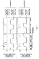
- the circuit board 520 provides control, supply, conditioning and distribution of current to the sensors 524, 528 and the EM coil 546 of the field generator 510, and output sensed angular position data such as shown in FIG. 4 .
- the control system includes an outer control loop with the EM coil controlled outside the inner loop utilizing the output sensed angular position data from the sensors and board control system, such as with the FIG. 4 output data used to determine and produce a control current to EM coil 546 to control a relative motion with the brake 500.
- the at least two power sources provide for power supply to the same sensor.
- the first power supply provides power to both sensors, with a backup secondary power supplied to the sensors from the second power supply.
- the 12 volt power to the circuit board 520 and the outputted sensed angular position data from the sensors are provided through the electronics outer loop conduit utilizing two separate cables routing the wiring into the second chamber 506.
- two separate cabled power supplies are supplied to the double sided board 520, with the circuit board 520 providing two isolated power supplies to a sensor.
- two separate cabled power supplies are supplied to the double sided board 520, with the circuit board 520 including electronics to send power to the EM brake coil 546, preferably at least with a control current 538 provided such as with the current control flyback diode steer current from two isolated power supplies supplied to the brake EM coil 546.
- the integrated oriented first and second sensors provide four detected target positions, preferably providing the absolute angular position of the rotating magnetic target 518, the shaft 512, and the rotor 508, preferably with the four outputs monitored and compared to detect a suspected erroneous output which in turn is ignored and not utilized in the determination of controlling the motion of the rotor with the field generator 510.
- FIG. 4 shows the positional outputs from two integrated circuit semiconductor sensor chip electronic noncontacting magnetic sensors 524, 528 mounted to opposing sides of a circuit board 520 for detecting the rotation of the target 518, the shaft 512, and the rotor 508.
- the at least two dies are vertically stacked dies in the integrated circuit semiconductor sensor chip.
- the integrated circuit semiconductor sensor chip ASIC die include a magnetoresistive material, preferably with electrical resistance changes relative to the rotating shaft magnetic target magnetic field, preferably with magnetoresistive elements arranged in a Wheatstone bridge.
- the integrated circuit semiconductor sensor chip ASIC die include a Hall Effect element, preferably a plurality of oriented Hall Effect elements, preferably silicon semiconductor Hall Effect elements which detect changes relative to the rotating magnetic target magnetic field of the rotating shaft magnetic target.
Landscapes
- Engineering & Computer Science (AREA)
- Mechanical Engineering (AREA)
- General Engineering & Computer Science (AREA)
- Transportation (AREA)
- Dynamo-Electric Clutches, Dynamo-Electric Brakes (AREA)
- Braking Systems And Boosters (AREA)
- Braking Arrangements (AREA)
Claims (7)
- Frein commandable (500) comprenant :- un boîtier (502) comprenant une première chambre (504) et une seconde chambre (506),- un arbre (512), l'arbre (512) s'étendant à travers la première chambre (504) et la seconde chambre (506) avec un axe de rotation (516), ledit arbre (512) ayant une première extrémité d'arbre (514),- un rotor de frein commandable (508) rendu solidaire de l'arbre (512), ledit rotor (508) étant reçu dans la première chambre (504),- un générateur de champ magnétique de frein commandable (510) situé dans la première chambre (504) à proximité du rotor de frein commandable (508), ledit générateur de champ magnétique de frein commandable (510) étant destiné à générer une intensité de champ magnétique commandable, et- une cible magnétique tournante de frein commandable (518) d'un seul tenant avec l'arbre (512) à proximité de ladite première extrémité d'arbre (514), ladite cible magnétique tournante de frein commandable (518) étant reçue dans la seconde chambre (506), et une carte de circuit électronique de frein commandable montée dans ladite seconde chambre, ladite carte de circuit électronique de frein commandable (520) ayant un plan de carte de commande (522), caractérisé par le fait que ledit plan de carte de commande (522) est orienté normal audit axe de rotation (516), un premier capteur magnétique électronique sans contact (524) a un premier plan de capteur (526), ledit premier capteur magnétique électronique sans contact (524) étant intégré sur ladite carte de circuit électronique de frein commandable (520) avec ledit premier plan de capteur (526) parallèle audit plan de carte de commande (522), un second capteur magnétique électronique sans contact (528) a un second plan de capteur (530), ledit second capteur magnétique électronique sans contact (518) étant intégré sur ladite carte de circuit électronique de frein commandable (526) avec ledit second plan de capteur (530) parallèle audit plan de carte de commande (520) avec ledit plan de carte de commande (520) entre ledit premier plan de capteur (526) et ledit second plan de capteur (530), ledit premier capteur magnétique électronique sans contact (524) et ledit second capteur magnétique électronique sans contact (526) surveillant la rotation de ladite cible magnétique tournante de frein commandable (518) et délivrant en sortie une position en rotation de ladite cible magnétique tournante de frein commandable (518), l'intensité de champ magnétique commandable générée par ledit générateur de champ magnétique de frein commandable (510) étant déterminée par ladite position en rotation pour commander un mouvement relatif dudit rotor de frein commandable (508).
- Frein commandable selon la revendication 1, dans lequel ladite cible magnétique tournante (518) du frein commandable (500) est constituée d'un aimant permanent ayant un pôle nord et un pôle sud opposés le long d'un axe nord-sud (534), ledit axe nord-sud (534) étant perpendiculaire audit axe de rotation d'arbre (516).
- Frein commandable selon la revendication 1, ledit frein commandable (500) comprenant une matière commandable répondant au champ (504) dans ladite première chambre (504), ladite matière commandable répondant au champ étant affectée par ladite intensité de champ magnétique commandable et ledit générateur de champ magnétique (510) étant apte à générer un flux magnétique dans une direction passant à travers ladite matière commandable répondant au champ (532) vers ledit rotor (508).
- Frein commandable selon la revendication 1, ledit frein commandable (500) comprenant une matière commandable répondant au champ (532) scellée de manière étanche dans ladite première chambre (504) avec une rhéologue de ladite matière commandable répondant au champ qui est affectée par ladite intensité de champ magnétique commandable, et ledit générateur de champ magnétique (510) étant apte à générer un flux magnétique dans une direction passant à travers ladite matière commandable répondant au champ (532) vers ledit rotor (508), et ladite carte de circuit électronique de frein commandable (522) fournissant un courant commandé audit générateur de champ magnétique (510).
- Frein commandable selon la revendication 1, dans lequel ledit générateur de champ magnétique (510) comprend une bobine électromagnétique et ladite carte de circuit électronique de frein commandable (522) est électriquement reliée à ladite bobine électromagnétique de générateur de champ magnétique.
- Frein commandable selon la revendication 1, dans lequel ledit capteur magnétique électronique sans contact (524) comprend une matière magnétorésistive.
- Frein commandable selon la revendication 1, dans lequel ledit capteur magnétique électronique sans contact (524) comprend un élément à effet Hall.
Applications Claiming Priority (2)
| Application Number | Priority Date | Filing Date | Title |
|---|---|---|---|
| US87161006P | 2006-12-22 | 2006-12-22 | |
| PCT/US2007/088574 WO2008080070A2 (fr) | 2006-12-22 | 2007-12-21 | Frein pourvu d'un matériau répondant au champ magnétique |
Publications (2)
| Publication Number | Publication Date |
|---|---|
| EP2094550A2 EP2094550A2 (fr) | 2009-09-02 |
| EP2094550B1 true EP2094550B1 (fr) | 2014-03-12 |
Family
ID=39433718
Family Applications (1)
| Application Number | Title | Priority Date | Filing Date |
|---|---|---|---|
| EP07865968.7A Active EP2094550B1 (fr) | 2006-12-22 | 2007-12-21 | Frein pourvu d'un matériau répondant au champ magnétique |
Country Status (3)
| Country | Link |
|---|---|
| US (1) | US20100294603A1 (fr) |
| EP (1) | EP2094550B1 (fr) |
| WO (1) | WO2008080070A2 (fr) |
Families Citing this family (4)
| Publication number | Priority date | Publication date | Assignee | Title |
|---|---|---|---|---|
| US8397883B2 (en) * | 2001-10-25 | 2013-03-19 | Lord Corporation | Brake with field responsive material |
| WO2008080078A2 (fr) * | 2006-12-22 | 2008-07-03 | Lord Corporation | Frein commandable à interface d'opérateur, pourvu d'un matériau répondant à un champ magnétique |
| US20080234908A1 (en) * | 2007-03-07 | 2008-09-25 | St Clair Kenneth A | Operator input device for controlling a vehicle operation |
| US9513202B2 (en) * | 2012-08-14 | 2016-12-06 | BEL Legacy Corporation | Viscometer |
Family Cites Families (20)
| Publication number | Priority date | Publication date | Assignee | Title |
|---|---|---|---|---|
| US2695675A (en) * | 1950-03-08 | 1954-11-30 | Frye Jack | Control for magnetic fluid transmission drive to vehicle wheels |
| US3305055A (en) * | 1964-08-21 | 1967-02-21 | Clarence S Slaughter | Fluid particle coupling |
| US4200003A (en) * | 1976-03-29 | 1980-04-29 | Facet Enterprises, Inc. | Magnetic viscous damper |
| US4673876A (en) * | 1984-03-08 | 1987-06-16 | General Scanning, Inc. | Two-element angular positive sensor for rotatable shaft |
| US5598908A (en) * | 1995-06-05 | 1997-02-04 | Gse, Inc. | Magnetorheological fluid coupling device and torque load simulator system |
| US5596272A (en) * | 1995-09-21 | 1997-01-21 | Honeywell Inc. | Magnetic sensor with a beveled permanent magnet |
| DE19546595A1 (de) * | 1995-12-13 | 1997-06-19 | Siemens Ag | Drehzahl- und/oder Drehrichtung-Sensorvorrichtung |
| EP0916074B1 (fr) * | 1997-05-29 | 2003-07-30 | AMS International AG | Capteur de rotation magnetique |
| JP3941082B2 (ja) * | 1998-01-28 | 2007-07-04 | 株式会社安川電機 | 磁気式検出器 |
| DE19848186A1 (de) * | 1998-10-20 | 2000-04-27 | Volkswagen Ag | Pedaleinrichtung |
| US6326781B1 (en) * | 1999-01-11 | 2001-12-04 | Bvr Aero Precision Corp | 360 degree shaft angle sensing and remote indicating system using a two-axis magnetoresistive microcircuit |
| US6691839B1 (en) * | 1999-07-19 | 2004-02-17 | Axletech International Ip Holdings, Llc | Reduced drag wet disc brake |
| US6293077B1 (en) * | 2000-05-02 | 2001-09-25 | Mtd Products Inc | Deck attachment and lift system |
| FR2816047B1 (fr) * | 2000-11-02 | 2003-02-07 | Skf Ab | Dispositif de palier a roulement instrumente, notamment pour volant de commande |
| US6538429B2 (en) * | 2001-02-09 | 2003-03-25 | Delphi Technologies, Inc. | Angular position sensor assembly for a motor vehicle generator shaft |
| EP1417496B1 (fr) * | 2001-07-27 | 2010-10-13 | Delphi Technologies, Inc. | Tachymetre et procede de mesure de la vitesse d'un moteur |
| US8397883B2 (en) * | 2001-10-25 | 2013-03-19 | Lord Corporation | Brake with field responsive material |
| US6854573B2 (en) * | 2001-10-25 | 2005-02-15 | Lord Corporation | Brake with field responsive material |
| JP3958115B2 (ja) * | 2002-05-28 | 2007-08-15 | ナイルス株式会社 | 回転検出装置 |
| DE102005052310A1 (de) * | 2004-11-03 | 2006-07-06 | Continental Teves Ag & Co. Ohg | Bremsbetätigungseinheit SBA |
-
2007
- 2007-12-21 US US12/520,782 patent/US20100294603A1/en not_active Abandoned
- 2007-12-21 WO PCT/US2007/088574 patent/WO2008080070A2/fr active Application Filing
- 2007-12-21 EP EP07865968.7A patent/EP2094550B1/fr active Active
Also Published As
| Publication number | Publication date |
|---|---|
| US20100294603A1 (en) | 2010-11-25 |
| WO2008080070A2 (fr) | 2008-07-03 |
| WO2008080070A9 (fr) | 2008-08-14 |
| EP2094550A2 (fr) | 2009-09-02 |
| WO2008080070A3 (fr) | 2008-10-23 |
Similar Documents
| Publication | Publication Date | Title |
|---|---|---|
| EP2913237B1 (fr) | Frein contrôlable à interface opérateur avec matériau sensible aux champs | |
| EP2454558B1 (fr) | Agencement de capteur à effet hall | |
| US8397883B2 (en) | Brake with field responsive material | |
| EP2094550B1 (fr) | Frein pourvu d'un matériau répondant au champ magnétique | |
| CN105993117B (zh) | 电机 | |
| CN107450035A (zh) | 紧凑的传感器封装 | |
| US20160041007A1 (en) | Hall Sensor Insensitive to External Magnetic Fields | |
| US8593136B2 (en) | Measuring apparatus for the detection of a relative movement | |
| US7382120B2 (en) | Rotary position sensor with rectangular magnet and hall sensors placed in association with the surface of the magnet | |
| US20090293637A1 (en) | Flow Rate Sensor | |
| JP7366731B2 (ja) | センサ | |
| JP4250418B2 (ja) | ステアリングホイール用の計装付き軸受け | |
| US20210063204A1 (en) | Integrated rotation angle determining sensor unit in a measuring system for determining a rotation angle | |
| US20060113989A1 (en) | Redundant pedal position sensor | |
| CN104180752A (zh) | 转轴角度位置感测装置及感测系统 | |
| WO2006087627A1 (fr) | Dispositif de surveillance | |
| US20080234908A1 (en) | Operator input device for controlling a vehicle operation | |
| JP2008216172A (ja) | トルクセンサ及び電動式パワーステアリング装置 | |
| CA2097187C (fr) | Detecteur de vitesse angulaire basse frequence | |
| EP1774343A1 (fr) | Capteur de direction et de vitesse magnetoresistant integre | |
| CN203274677U (zh) | 转轴角度位置感测装置及感测系统 | |
| US11543311B2 (en) | Integrated torque and angle sensor for steering column monitoring with improved performance | |
| WO2007041465A1 (fr) | Capteur d’angle redondant | |
| JP2013210215A (ja) | 慣性センサモジュール | |
| US7078915B1 (en) | Angular position sensor for rotating components such as steering columns |
Legal Events
| Date | Code | Title | Description |
|---|---|---|---|
| PUAI | Public reference made under article 153(3) epc to a published international application that has entered the european phase |
Free format text: ORIGINAL CODE: 0009012 |
|
| 17P | Request for examination filed |
Effective date: 20090707 |
|
| AK | Designated contracting states |
Kind code of ref document: A2 Designated state(s): AT BE BG CH CY CZ DE DK EE ES FI FR GB GR HU IE IS IT LI LT LU LV MC MT NL PL PT RO SE SI SK TR |
|
| RIN1 | Information on inventor provided before grant (corrected) |
Inventor name: HONTZ, MARLENE Inventor name: MARJORAM, ROBERT H. Inventor name: KOESTER, STEPHEN Inventor name: HARDIN, WILLIAM C. Inventor name: ST. CLAIR, KENNETH A. |
|
| DAX | Request for extension of the european patent (deleted) | ||
| 17Q | First examination report despatched |
Effective date: 20100409 |
|
| GRAP | Despatch of communication of intention to grant a patent |
Free format text: ORIGINAL CODE: EPIDOSNIGR1 |
|
| INTG | Intention to grant announced |
Effective date: 20130923 |
|
| GRAS | Grant fee paid |
Free format text: ORIGINAL CODE: EPIDOSNIGR3 |
|
| GRAA | (expected) grant |
Free format text: ORIGINAL CODE: 0009210 |
|
| AK | Designated contracting states |
Kind code of ref document: B1 Designated state(s): AT BE BG CH CY CZ DE DK EE ES FI FR GB GR HU IE IS IT LI LT LU LV MC MT NL PL PT RO SE SI SK TR |
|
| REG | Reference to a national code |
Ref country code: GB Ref legal event code: FG4D |
|
| REG | Reference to a national code |
Ref country code: CH Ref legal event code: EP |
|
| REG | Reference to a national code |
Ref country code: AT Ref legal event code: REF Ref document number: 656065 Country of ref document: AT Kind code of ref document: T Effective date: 20140315 |
|
| REG | Reference to a national code |
Ref country code: IE Ref legal event code: FG4D |
|
| REG | Reference to a national code |
Ref country code: DE Ref legal event code: R096 Ref document number: 602007035597 Country of ref document: DE Effective date: 20140424 |
|
| REG | Reference to a national code |
Ref country code: NL Ref legal event code: VDEP Effective date: 20140312 |
|
| PG25 | Lapsed in a contracting state [announced via postgrant information from national office to epo] |
Ref country code: LT Free format text: LAPSE BECAUSE OF FAILURE TO SUBMIT A TRANSLATION OF THE DESCRIPTION OR TO PAY THE FEE WITHIN THE PRESCRIBED TIME-LIMIT Effective date: 20140312 |
|
| REG | Reference to a national code |
Ref country code: AT Ref legal event code: MK05 Ref document number: 656065 Country of ref document: AT Kind code of ref document: T Effective date: 20140312 |
|
| REG | Reference to a national code |
Ref country code: LT Ref legal event code: MG4D |
|
| PG25 | Lapsed in a contracting state [announced via postgrant information from national office to epo] |
Ref country code: SE Free format text: LAPSE BECAUSE OF FAILURE TO SUBMIT A TRANSLATION OF THE DESCRIPTION OR TO PAY THE FEE WITHIN THE PRESCRIBED TIME-LIMIT Effective date: 20140312 Ref country code: FI Free format text: LAPSE BECAUSE OF FAILURE TO SUBMIT A TRANSLATION OF THE DESCRIPTION OR TO PAY THE FEE WITHIN THE PRESCRIBED TIME-LIMIT Effective date: 20140312 Ref country code: CY Free format text: LAPSE BECAUSE OF FAILURE TO SUBMIT A TRANSLATION OF THE DESCRIPTION OR TO PAY THE FEE WITHIN THE PRESCRIBED TIME-LIMIT Effective date: 20140312 |
|
| PG25 | Lapsed in a contracting state [announced via postgrant information from national office to epo] |
Ref country code: LV Free format text: LAPSE BECAUSE OF FAILURE TO SUBMIT A TRANSLATION OF THE DESCRIPTION OR TO PAY THE FEE WITHIN THE PRESCRIBED TIME-LIMIT Effective date: 20140312 |
|
| PG25 | Lapsed in a contracting state [announced via postgrant information from national office to epo] |
Ref country code: CZ Free format text: LAPSE BECAUSE OF FAILURE TO SUBMIT A TRANSLATION OF THE DESCRIPTION OR TO PAY THE FEE WITHIN THE PRESCRIBED TIME-LIMIT Effective date: 20140312 Ref country code: BG Free format text: LAPSE BECAUSE OF FAILURE TO SUBMIT A TRANSLATION OF THE DESCRIPTION OR TO PAY THE FEE WITHIN THE PRESCRIBED TIME-LIMIT Effective date: 20140612 Ref country code: IS Free format text: LAPSE BECAUSE OF FAILURE TO SUBMIT A TRANSLATION OF THE DESCRIPTION OR TO PAY THE FEE WITHIN THE PRESCRIBED TIME-LIMIT Effective date: 20140712 Ref country code: EE Free format text: LAPSE BECAUSE OF FAILURE TO SUBMIT A TRANSLATION OF THE DESCRIPTION OR TO PAY THE FEE WITHIN THE PRESCRIBED TIME-LIMIT Effective date: 20140312 Ref country code: RO Free format text: LAPSE BECAUSE OF FAILURE TO SUBMIT A TRANSLATION OF THE DESCRIPTION OR TO PAY THE FEE WITHIN THE PRESCRIBED TIME-LIMIT Effective date: 20140312 Ref country code: BE Free format text: LAPSE BECAUSE OF FAILURE TO SUBMIT A TRANSLATION OF THE DESCRIPTION OR TO PAY THE FEE WITHIN THE PRESCRIBED TIME-LIMIT Effective date: 20140312 Ref country code: NL Free format text: LAPSE BECAUSE OF FAILURE TO SUBMIT A TRANSLATION OF THE DESCRIPTION OR TO PAY THE FEE WITHIN THE PRESCRIBED TIME-LIMIT Effective date: 20140312 |
|
| PG25 | Lapsed in a contracting state [announced via postgrant information from national office to epo] |
Ref country code: AT Free format text: LAPSE BECAUSE OF FAILURE TO SUBMIT A TRANSLATION OF THE DESCRIPTION OR TO PAY THE FEE WITHIN THE PRESCRIBED TIME-LIMIT Effective date: 20140312 Ref country code: SK Free format text: LAPSE BECAUSE OF FAILURE TO SUBMIT A TRANSLATION OF THE DESCRIPTION OR TO PAY THE FEE WITHIN THE PRESCRIBED TIME-LIMIT Effective date: 20140312 Ref country code: PL Free format text: LAPSE BECAUSE OF FAILURE TO SUBMIT A TRANSLATION OF THE DESCRIPTION OR TO PAY THE FEE WITHIN THE PRESCRIBED TIME-LIMIT Effective date: 20140312 Ref country code: ES Free format text: LAPSE BECAUSE OF FAILURE TO SUBMIT A TRANSLATION OF THE DESCRIPTION OR TO PAY THE FEE WITHIN THE PRESCRIBED TIME-LIMIT Effective date: 20140312 |
|
| REG | Reference to a national code |
Ref country code: DE Ref legal event code: R097 Ref document number: 602007035597 Country of ref document: DE |
|
| PG25 | Lapsed in a contracting state [announced via postgrant information from national office to epo] |
Ref country code: PT Free format text: LAPSE BECAUSE OF FAILURE TO SUBMIT A TRANSLATION OF THE DESCRIPTION OR TO PAY THE FEE WITHIN THE PRESCRIBED TIME-LIMIT Effective date: 20140714 |
|
| PLBE | No opposition filed within time limit |
Free format text: ORIGINAL CODE: 0009261 |
|
| STAA | Information on the status of an ep patent application or granted ep patent |
Free format text: STATUS: NO OPPOSITION FILED WITHIN TIME LIMIT |
|
| PG25 | Lapsed in a contracting state [announced via postgrant information from national office to epo] |
Ref country code: DK Free format text: LAPSE BECAUSE OF FAILURE TO SUBMIT A TRANSLATION OF THE DESCRIPTION OR TO PAY THE FEE WITHIN THE PRESCRIBED TIME-LIMIT Effective date: 20140312 |
|
| 26N | No opposition filed |
Effective date: 20141215 |
|
| REG | Reference to a national code |
Ref country code: DE Ref legal event code: R097 Ref document number: 602007035597 Country of ref document: DE Effective date: 20141215 |
|
| PG25 | Lapsed in a contracting state [announced via postgrant information from national office to epo] |
Ref country code: LU Free format text: LAPSE BECAUSE OF FAILURE TO SUBMIT A TRANSLATION OF THE DESCRIPTION OR TO PAY THE FEE WITHIN THE PRESCRIBED TIME-LIMIT Effective date: 20141221 Ref country code: SI Free format text: LAPSE BECAUSE OF FAILURE TO SUBMIT A TRANSLATION OF THE DESCRIPTION OR TO PAY THE FEE WITHIN THE PRESCRIBED TIME-LIMIT Effective date: 20140312 |
|
| REG | Reference to a national code |
Ref country code: CH Ref legal event code: PL |
|
| REG | Reference to a national code |
Ref country code: IE Ref legal event code: MM4A |
|
| PG25 | Lapsed in a contracting state [announced via postgrant information from national office to epo] |
Ref country code: IE Free format text: LAPSE BECAUSE OF NON-PAYMENT OF DUE FEES Effective date: 20141221 Ref country code: LI Free format text: LAPSE BECAUSE OF NON-PAYMENT OF DUE FEES Effective date: 20141231 Ref country code: CH Free format text: LAPSE BECAUSE OF NON-PAYMENT OF DUE FEES Effective date: 20141231 |
|
| REG | Reference to a national code |
Ref country code: FR Ref legal event code: PLFP Year of fee payment: 9 |
|
| PG25 | Lapsed in a contracting state [announced via postgrant information from national office to epo] |
Ref country code: MC Free format text: LAPSE BECAUSE OF FAILURE TO SUBMIT A TRANSLATION OF THE DESCRIPTION OR TO PAY THE FEE WITHIN THE PRESCRIBED TIME-LIMIT Effective date: 20140312 |
|
| PG25 | Lapsed in a contracting state [announced via postgrant information from national office to epo] |
Ref country code: GR Free format text: LAPSE BECAUSE OF FAILURE TO SUBMIT A TRANSLATION OF THE DESCRIPTION OR TO PAY THE FEE WITHIN THE PRESCRIBED TIME-LIMIT Effective date: 20140613 |
|
| PG25 | Lapsed in a contracting state [announced via postgrant information from national office to epo] |
Ref country code: TR Free format text: LAPSE BECAUSE OF FAILURE TO SUBMIT A TRANSLATION OF THE DESCRIPTION OR TO PAY THE FEE WITHIN THE PRESCRIBED TIME-LIMIT Effective date: 20140312 Ref country code: HU Free format text: LAPSE BECAUSE OF FAILURE TO SUBMIT A TRANSLATION OF THE DESCRIPTION OR TO PAY THE FEE WITHIN THE PRESCRIBED TIME-LIMIT; INVALID AB INITIO Effective date: 20071221 Ref country code: MT Free format text: LAPSE BECAUSE OF FAILURE TO SUBMIT A TRANSLATION OF THE DESCRIPTION OR TO PAY THE FEE WITHIN THE PRESCRIBED TIME-LIMIT Effective date: 20140312 |
|
| REG | Reference to a national code |
Ref country code: FR Ref legal event code: PLFP Year of fee payment: 10 |
|
| REG | Reference to a national code |
Ref country code: FR Ref legal event code: PLFP Year of fee payment: 11 |
|
| P01 | Opt-out of the competence of the unified patent court (upc) registered |
Effective date: 20230524 |
|
| REG | Reference to a national code |
Ref country code: DE Ref legal event code: R082 Ref document number: 602007035597 Country of ref document: DE Representative=s name: KANDLBINDER, MARKUS, DIPL.-PHYS., DE |
|
| PGFP | Annual fee paid to national office [announced via postgrant information from national office to epo] |
Ref country code: GB Payment date: 20231227 Year of fee payment: 17 |
|
| PGFP | Annual fee paid to national office [announced via postgrant information from national office to epo] |
Ref country code: IT Payment date: 20231220 Year of fee payment: 17 Ref country code: FR Payment date: 20231227 Year of fee payment: 17 |
|
| PGFP | Annual fee paid to national office [announced via postgrant information from national office to epo] |
Ref country code: DE Payment date: 20231229 Year of fee payment: 17 |