EP2094312B1 - Furnace and equipment for producing sterile vessels from decontaminated preforms of a thermoplastic material - Google Patents
Furnace and equipment for producing sterile vessels from decontaminated preforms of a thermoplastic material Download PDFInfo
- Publication number
- EP2094312B1 EP2094312B1 EP07821821A EP07821821A EP2094312B1 EP 2094312 B1 EP2094312 B1 EP 2094312B1 EP 07821821 A EP07821821 A EP 07821821A EP 07821821 A EP07821821 A EP 07821821A EP 2094312 B1 EP2094312 B1 EP 2094312B1
- Authority
- EP
- European Patent Office
- Prior art keywords
- preform
- zone
- heating
- preforms
- oven
- Prior art date
- Legal status (The legal status is an assumption and is not a legal conclusion. Google has not performed a legal analysis and makes no representation as to the accuracy of the status listed.)
- Active
Links
- 239000012815 thermoplastic material Substances 0.000 title description 2
- 230000001954 sterilising effect Effects 0.000 claims abstract description 125
- 238000010438 heat treatment Methods 0.000 claims abstract description 112
- 238000005202 decontamination Methods 0.000 claims abstract description 46
- 230000003588 decontaminative effect Effects 0.000 claims abstract description 46
- 238000009434 installation Methods 0.000 claims abstract description 27
- 238000004659 sterilization and disinfection Methods 0.000 claims description 76
- 238000004519 manufacturing process Methods 0.000 claims description 26
- 230000005855 radiation Effects 0.000 claims description 24
- 238000000465 moulding Methods 0.000 claims description 18
- 238000009833 condensation Methods 0.000 claims description 11
- 230000005494 condensation Effects 0.000 claims description 11
- 238000001704 evaporation Methods 0.000 claims description 11
- 230000008020 evaporation Effects 0.000 claims description 11
- 238000001816 cooling Methods 0.000 claims description 10
- 229920001169 thermoplastic Polymers 0.000 claims description 10
- 239000004416 thermosoftening plastic Substances 0.000 claims description 10
- 238000011144 upstream manufacturing Methods 0.000 claims description 10
- 230000004913 activation Effects 0.000 claims description 7
- 230000003750 conditioning effect Effects 0.000 abstract description 14
- 238000000034 method Methods 0.000 abstract description 14
- 210000003739 neck Anatomy 0.000 description 35
- 208000031968 Cadaver Diseases 0.000 description 21
- 238000000071 blow moulding Methods 0.000 description 15
- 244000052616 bacterial pathogen Species 0.000 description 12
- 238000007664 blowing Methods 0.000 description 11
- 239000000243 solution Substances 0.000 description 10
- MHAJPDPJQMAIIY-UHFFFAOYSA-N Hydrogen peroxide Chemical compound OO MHAJPDPJQMAIIY-UHFFFAOYSA-N 0.000 description 9
- 229920000297 Rayon Polymers 0.000 description 8
- 229920000139 polyethylene terephthalate Polymers 0.000 description 8
- 239000005020 polyethylene terephthalate Substances 0.000 description 8
- 230000008569 process Effects 0.000 description 8
- 239000002964 rayon Substances 0.000 description 8
- 241000894006 Bacteria Species 0.000 description 7
- 230000036512 infertility Effects 0.000 description 7
- 239000000463 material Substances 0.000 description 7
- 230000035515 penetration Effects 0.000 description 6
- 239000003595 mist Substances 0.000 description 5
- 238000011109 contamination Methods 0.000 description 4
- 238000006073 displacement reaction Methods 0.000 description 4
- 239000007788 liquid Substances 0.000 description 4
- -1 polyethylene terephthalate Polymers 0.000 description 4
- 230000009467 reduction Effects 0.000 description 4
- 239000007921 spray Substances 0.000 description 4
- 238000012864 cross contamination Methods 0.000 description 3
- 238000011068 loading method Methods 0.000 description 3
- 238000005507 spraying Methods 0.000 description 3
- 238000009281 ultraviolet germicidal irradiation Methods 0.000 description 3
- 241000193830 Bacillus <bacterium> Species 0.000 description 2
- 230000001143 conditioned effect Effects 0.000 description 2
- 239000000470 constituent Substances 0.000 description 2
- 230000008021 deposition Effects 0.000 description 2
- 238000011049 filling Methods 0.000 description 2
- 238000001914 filtration Methods 0.000 description 2
- 238000002513 implantation Methods 0.000 description 2
- 239000004033 plastic Substances 0.000 description 2
- 229920003023 plastic Polymers 0.000 description 2
- 230000001131 transforming effect Effects 0.000 description 2
- 238000009736 wetting Methods 0.000 description 2
- 230000009471 action Effects 0.000 description 1
- 230000003213 activating effect Effects 0.000 description 1
- 238000004500 asepsis Methods 0.000 description 1
- 230000015572 biosynthetic process Effects 0.000 description 1
- 150000001875 compounds Chemical class 0.000 description 1
- 238000012258 culturing Methods 0.000 description 1
- 230000006378 damage Effects 0.000 description 1
- 230000007423 decrease Effects 0.000 description 1
- 230000000694 effects Effects 0.000 description 1
- 230000008030 elimination Effects 0.000 description 1
- 238000003379 elimination reaction Methods 0.000 description 1
- 239000012530 fluid Substances 0.000 description 1
- 230000004907 flux Effects 0.000 description 1
- 239000007789 gas Substances 0.000 description 1
- 230000014509 gene expression Effects 0.000 description 1
- 230000009477 glass transition Effects 0.000 description 1
- 230000005484 gravity Effects 0.000 description 1
- 238000002347 injection Methods 0.000 description 1
- 239000007924 injection Substances 0.000 description 1
- 238000001746 injection moulding Methods 0.000 description 1
- 230000001678 irradiating effect Effects 0.000 description 1
- 230000002427 irreversible effect Effects 0.000 description 1
- 230000004048 modification Effects 0.000 description 1
- 238000012986 modification Methods 0.000 description 1
- 238000013021 overheating Methods 0.000 description 1
- 230000000149 penetrating effect Effects 0.000 description 1
- 230000001737 promoting effect Effects 0.000 description 1
- 238000007789 sealing Methods 0.000 description 1
- 238000002791 soaking Methods 0.000 description 1
- 239000000126 substance Substances 0.000 description 1
- 230000009897 systematic effect Effects 0.000 description 1
- 230000028016 temperature homeostasis Effects 0.000 description 1
- 230000009466 transformation Effects 0.000 description 1
- 238000009423 ventilation Methods 0.000 description 1
- 238000005406 washing Methods 0.000 description 1
Images
Classifications
-
- A—HUMAN NECESSITIES
- A61—MEDICAL OR VETERINARY SCIENCE; HYGIENE
- A61L—METHODS OR APPARATUS FOR STERILISING MATERIALS OR OBJECTS IN GENERAL; DISINFECTION, STERILISATION OR DEODORISATION OF AIR; CHEMICAL ASPECTS OF BANDAGES, DRESSINGS, ABSORBENT PADS OR SURGICAL ARTICLES; MATERIALS FOR BANDAGES, DRESSINGS, ABSORBENT PADS OR SURGICAL ARTICLES
- A61L2/00—Methods or apparatus for disinfecting or sterilising materials or objects other than foodstuffs or contact lenses; Accessories therefor
- A61L2/02—Methods or apparatus for disinfecting or sterilising materials or objects other than foodstuffs or contact lenses; Accessories therefor using physical phenomena
- A61L2/08—Radiation
- A61L2/10—Ultra-violet radiation
-
- A—HUMAN NECESSITIES
- A61—MEDICAL OR VETERINARY SCIENCE; HYGIENE
- A61L—METHODS OR APPARATUS FOR STERILISING MATERIALS OR OBJECTS IN GENERAL; DISINFECTION, STERILISATION OR DEODORISATION OF AIR; CHEMICAL ASPECTS OF BANDAGES, DRESSINGS, ABSORBENT PADS OR SURGICAL ARTICLES; MATERIALS FOR BANDAGES, DRESSINGS, ABSORBENT PADS OR SURGICAL ARTICLES
- A61L2/00—Methods or apparatus for disinfecting or sterilising materials or objects other than foodstuffs or contact lenses; Accessories therefor
- A61L2/02—Methods or apparatus for disinfecting or sterilising materials or objects other than foodstuffs or contact lenses; Accessories therefor using physical phenomena
- A61L2/04—Heat
-
- A—HUMAN NECESSITIES
- A61—MEDICAL OR VETERINARY SCIENCE; HYGIENE
- A61L—METHODS OR APPARATUS FOR STERILISING MATERIALS OR OBJECTS IN GENERAL; DISINFECTION, STERILISATION OR DEODORISATION OF AIR; CHEMICAL ASPECTS OF BANDAGES, DRESSINGS, ABSORBENT PADS OR SURGICAL ARTICLES; MATERIALS FOR BANDAGES, DRESSINGS, ABSORBENT PADS OR SURGICAL ARTICLES
- A61L2/00—Methods or apparatus for disinfecting or sterilising materials or objects other than foodstuffs or contact lenses; Accessories therefor
- A61L2/16—Methods or apparatus for disinfecting or sterilising materials or objects other than foodstuffs or contact lenses; Accessories therefor using chemical substances
- A61L2/20—Gaseous substances, e.g. vapours
- A61L2/208—Hydrogen peroxide
-
- B—PERFORMING OPERATIONS; TRANSPORTING
- B29—WORKING OF PLASTICS; WORKING OF SUBSTANCES IN A PLASTIC STATE IN GENERAL
- B29C—SHAPING OR JOINING OF PLASTICS; SHAPING OF MATERIAL IN A PLASTIC STATE, NOT OTHERWISE PROVIDED FOR; AFTER-TREATMENT OF THE SHAPED PRODUCTS, e.g. REPAIRING
- B29C49/00—Blow-moulding, i.e. blowing a preform or parison to a desired shape within a mould; Apparatus therefor
- B29C49/42—Component parts, details or accessories; Auxiliary operations
- B29C49/64—Heating or cooling preforms, parisons or blown articles
- B29C49/6409—Thermal conditioning of preforms
-
- B—PERFORMING OPERATIONS; TRANSPORTING
- B29—WORKING OF PLASTICS; WORKING OF SUBSTANCES IN A PLASTIC STATE IN GENERAL
- B29C—SHAPING OR JOINING OF PLASTICS; SHAPING OF MATERIAL IN A PLASTIC STATE, NOT OTHERWISE PROVIDED FOR; AFTER-TREATMENT OF THE SHAPED PRODUCTS, e.g. REPAIRING
- B29C49/00—Blow-moulding, i.e. blowing a preform or parison to a desired shape within a mould; Apparatus therefor
- B29C49/42—Component parts, details or accessories; Auxiliary operations
- B29C49/64—Heating or cooling preforms, parisons or blown articles
- B29C49/68—Ovens specially adapted for heating preforms or parisons
-
- A—HUMAN NECESSITIES
- A61—MEDICAL OR VETERINARY SCIENCE; HYGIENE
- A61L—METHODS OR APPARATUS FOR STERILISING MATERIALS OR OBJECTS IN GENERAL; DISINFECTION, STERILISATION OR DEODORISATION OF AIR; CHEMICAL ASPECTS OF BANDAGES, DRESSINGS, ABSORBENT PADS OR SURGICAL ARTICLES; MATERIALS FOR BANDAGES, DRESSINGS, ABSORBENT PADS OR SURGICAL ARTICLES
- A61L2202/00—Aspects relating to methods or apparatus for disinfecting or sterilising materials or objects
- A61L2202/20—Targets to be treated
- A61L2202/23—Containers, e.g. vials, bottles, syringes, mail
-
- B—PERFORMING OPERATIONS; TRANSPORTING
- B29—WORKING OF PLASTICS; WORKING OF SUBSTANCES IN A PLASTIC STATE IN GENERAL
- B29C—SHAPING OR JOINING OF PLASTICS; SHAPING OF MATERIAL IN A PLASTIC STATE, NOT OTHERWISE PROVIDED FOR; AFTER-TREATMENT OF THE SHAPED PRODUCTS, e.g. REPAIRING
- B29C35/00—Heating, cooling or curing, e.g. crosslinking or vulcanising; Apparatus therefor
- B29C35/02—Heating or curing, e.g. crosslinking or vulcanizing during moulding, e.g. in a mould
- B29C35/08—Heating or curing, e.g. crosslinking or vulcanizing during moulding, e.g. in a mould by wave energy or particle radiation
- B29C35/0805—Heating or curing, e.g. crosslinking or vulcanizing during moulding, e.g. in a mould by wave energy or particle radiation using electromagnetic radiation
- B29C2035/0822—Heating or curing, e.g. crosslinking or vulcanizing during moulding, e.g. in a mould by wave energy or particle radiation using electromagnetic radiation using IR radiation
-
- B—PERFORMING OPERATIONS; TRANSPORTING
- B29—WORKING OF PLASTICS; WORKING OF SUBSTANCES IN A PLASTIC STATE IN GENERAL
- B29C—SHAPING OR JOINING OF PLASTICS; SHAPING OF MATERIAL IN A PLASTIC STATE, NOT OTHERWISE PROVIDED FOR; AFTER-TREATMENT OF THE SHAPED PRODUCTS, e.g. REPAIRING
- B29C35/00—Heating, cooling or curing, e.g. crosslinking or vulcanising; Apparatus therefor
- B29C35/02—Heating or curing, e.g. crosslinking or vulcanizing during moulding, e.g. in a mould
- B29C35/08—Heating or curing, e.g. crosslinking or vulcanizing during moulding, e.g. in a mould by wave energy or particle radiation
- B29C35/0805—Heating or curing, e.g. crosslinking or vulcanizing during moulding, e.g. in a mould by wave energy or particle radiation using electromagnetic radiation
- B29C2035/0827—Heating or curing, e.g. crosslinking or vulcanizing during moulding, e.g. in a mould by wave energy or particle radiation using electromagnetic radiation using UV radiation
-
- B—PERFORMING OPERATIONS; TRANSPORTING
- B29—WORKING OF PLASTICS; WORKING OF SUBSTANCES IN A PLASTIC STATE IN GENERAL
- B29C—SHAPING OR JOINING OF PLASTICS; SHAPING OF MATERIAL IN A PLASTIC STATE, NOT OTHERWISE PROVIDED FOR; AFTER-TREATMENT OF THE SHAPED PRODUCTS, e.g. REPAIRING
- B29C2949/00—Indexing scheme relating to blow-moulding
- B29C2949/07—Preforms or parisons characterised by their configuration
- B29C2949/0715—Preforms or parisons characterised by their configuration the preform having one end closed
-
- B—PERFORMING OPERATIONS; TRANSPORTING
- B29—WORKING OF PLASTICS; WORKING OF SUBSTANCES IN A PLASTIC STATE IN GENERAL
- B29C—SHAPING OR JOINING OF PLASTICS; SHAPING OF MATERIAL IN A PLASTIC STATE, NOT OTHERWISE PROVIDED FOR; AFTER-TREATMENT OF THE SHAPED PRODUCTS, e.g. REPAIRING
- B29C2949/00—Indexing scheme relating to blow-moulding
- B29C2949/20—Preforms or parisons whereby a specific part is made of only one component, e.g. only one layer
- B29C2949/22—Preforms or parisons whereby a specific part is made of only one component, e.g. only one layer at neck portion
-
- B—PERFORMING OPERATIONS; TRANSPORTING
- B29—WORKING OF PLASTICS; WORKING OF SUBSTANCES IN A PLASTIC STATE IN GENERAL
- B29C—SHAPING OR JOINING OF PLASTICS; SHAPING OF MATERIAL IN A PLASTIC STATE, NOT OTHERWISE PROVIDED FOR; AFTER-TREATMENT OF THE SHAPED PRODUCTS, e.g. REPAIRING
- B29C2949/00—Indexing scheme relating to blow-moulding
- B29C2949/20—Preforms or parisons whereby a specific part is made of only one component, e.g. only one layer
- B29C2949/24—Preforms or parisons whereby a specific part is made of only one component, e.g. only one layer at flange portion
-
- B—PERFORMING OPERATIONS; TRANSPORTING
- B29—WORKING OF PLASTICS; WORKING OF SUBSTANCES IN A PLASTIC STATE IN GENERAL
- B29C—SHAPING OR JOINING OF PLASTICS; SHAPING OF MATERIAL IN A PLASTIC STATE, NOT OTHERWISE PROVIDED FOR; AFTER-TREATMENT OF THE SHAPED PRODUCTS, e.g. REPAIRING
- B29C2949/00—Indexing scheme relating to blow-moulding
- B29C2949/20—Preforms or parisons whereby a specific part is made of only one component, e.g. only one layer
- B29C2949/26—Preforms or parisons whereby a specific part is made of only one component, e.g. only one layer at body portion
-
- B—PERFORMING OPERATIONS; TRANSPORTING
- B29—WORKING OF PLASTICS; WORKING OF SUBSTANCES IN A PLASTIC STATE IN GENERAL
- B29C—SHAPING OR JOINING OF PLASTICS; SHAPING OF MATERIAL IN A PLASTIC STATE, NOT OTHERWISE PROVIDED FOR; AFTER-TREATMENT OF THE SHAPED PRODUCTS, e.g. REPAIRING
- B29C2949/00—Indexing scheme relating to blow-moulding
- B29C2949/20—Preforms or parisons whereby a specific part is made of only one component, e.g. only one layer
- B29C2949/28—Preforms or parisons whereby a specific part is made of only one component, e.g. only one layer at bottom portion
-
- B—PERFORMING OPERATIONS; TRANSPORTING
- B29—WORKING OF PLASTICS; WORKING OF SUBSTANCES IN A PLASTIC STATE IN GENERAL
- B29C—SHAPING OR JOINING OF PLASTICS; SHAPING OF MATERIAL IN A PLASTIC STATE, NOT OTHERWISE PROVIDED FOR; AFTER-TREATMENT OF THE SHAPED PRODUCTS, e.g. REPAIRING
- B29C2949/00—Indexing scheme relating to blow-moulding
- B29C2949/30—Preforms or parisons made of several components
- B29C2949/3024—Preforms or parisons made of several components characterised by the number of components or by the manufacturing technique
-
- B—PERFORMING OPERATIONS; TRANSPORTING
- B29—WORKING OF PLASTICS; WORKING OF SUBSTANCES IN A PLASTIC STATE IN GENERAL
- B29C—SHAPING OR JOINING OF PLASTICS; SHAPING OF MATERIAL IN A PLASTIC STATE, NOT OTHERWISE PROVIDED FOR; AFTER-TREATMENT OF THE SHAPED PRODUCTS, e.g. REPAIRING
- B29C2949/00—Indexing scheme relating to blow-moulding
- B29C2949/30—Preforms or parisons made of several components
- B29C2949/3032—Preforms or parisons made of several components having components being injected
-
- B—PERFORMING OPERATIONS; TRANSPORTING
- B29—WORKING OF PLASTICS; WORKING OF SUBSTANCES IN A PLASTIC STATE IN GENERAL
- B29C—SHAPING OR JOINING OF PLASTICS; SHAPING OF MATERIAL IN A PLASTIC STATE, NOT OTHERWISE PROVIDED FOR; AFTER-TREATMENT OF THE SHAPED PRODUCTS, e.g. REPAIRING
- B29C49/00—Blow-moulding, i.e. blowing a preform or parison to a desired shape within a mould; Apparatus therefor
- B29C49/02—Combined blow-moulding and manufacture of the preform or the parison
- B29C49/06—Injection blow-moulding
-
- B—PERFORMING OPERATIONS; TRANSPORTING
- B29—WORKING OF PLASTICS; WORKING OF SUBSTANCES IN A PLASTIC STATE IN GENERAL
- B29C—SHAPING OR JOINING OF PLASTICS; SHAPING OF MATERIAL IN A PLASTIC STATE, NOT OTHERWISE PROVIDED FOR; AFTER-TREATMENT OF THE SHAPED PRODUCTS, e.g. REPAIRING
- B29C49/00—Blow-moulding, i.e. blowing a preform or parison to a desired shape within a mould; Apparatus therefor
- B29C49/42—Component parts, details or accessories; Auxiliary operations
- B29C49/4205—Handling means, e.g. transfer, loading or discharging means
- B29C49/42073—Grippers
- B29C49/42085—Grippers holding inside the neck
-
- B—PERFORMING OPERATIONS; TRANSPORTING
- B29—WORKING OF PLASTICS; WORKING OF SUBSTANCES IN A PLASTIC STATE IN GENERAL
- B29C—SHAPING OR JOINING OF PLASTICS; SHAPING OF MATERIAL IN A PLASTIC STATE, NOT OTHERWISE PROVIDED FOR; AFTER-TREATMENT OF THE SHAPED PRODUCTS, e.g. REPAIRING
- B29C49/00—Blow-moulding, i.e. blowing a preform or parison to a desired shape within a mould; Apparatus therefor
- B29C49/42—Component parts, details or accessories; Auxiliary operations
- B29C49/4205—Handling means, e.g. transfer, loading or discharging means
- B29C49/42093—Transporting apparatus, e.g. slides, wheels or conveyors
- B29C49/42105—Transporting apparatus, e.g. slides, wheels or conveyors for discontinuous or batch transport
-
- B—PERFORMING OPERATIONS; TRANSPORTING
- B29—WORKING OF PLASTICS; WORKING OF SUBSTANCES IN A PLASTIC STATE IN GENERAL
- B29C—SHAPING OR JOINING OF PLASTICS; SHAPING OF MATERIAL IN A PLASTIC STATE, NOT OTHERWISE PROVIDED FOR; AFTER-TREATMENT OF THE SHAPED PRODUCTS, e.g. REPAIRING
- B29C49/00—Blow-moulding, i.e. blowing a preform or parison to a desired shape within a mould; Apparatus therefor
- B29C49/42—Component parts, details or accessories; Auxiliary operations
- B29C49/42403—Purging or cleaning the blow-moulding apparatus
- B29C49/42405—Sterilizing
-
- B—PERFORMING OPERATIONS; TRANSPORTING
- B29—WORKING OF PLASTICS; WORKING OF SUBSTANCES IN A PLASTIC STATE IN GENERAL
- B29C—SHAPING OR JOINING OF PLASTICS; SHAPING OF MATERIAL IN A PLASTIC STATE, NOT OTHERWISE PROVIDED FOR; AFTER-TREATMENT OF THE SHAPED PRODUCTS, e.g. REPAIRING
- B29C49/00—Blow-moulding, i.e. blowing a preform or parison to a desired shape within a mould; Apparatus therefor
- B29C49/42—Component parts, details or accessories; Auxiliary operations
- B29C49/42414—Treatment of preforms, e.g. cleaning or spraying water for improved heat transfer
- B29C49/42416—Purging or cleaning the preforms
- B29C49/42418—Purging or cleaning the preforms for sterilizing
-
- B—PERFORMING OPERATIONS; TRANSPORTING
- B29—WORKING OF PLASTICS; WORKING OF SUBSTANCES IN A PLASTIC STATE IN GENERAL
- B29C—SHAPING OR JOINING OF PLASTICS; SHAPING OF MATERIAL IN A PLASTIC STATE, NOT OTHERWISE PROVIDED FOR; AFTER-TREATMENT OF THE SHAPED PRODUCTS, e.g. REPAIRING
- B29C49/00—Blow-moulding, i.e. blowing a preform or parison to a desired shape within a mould; Apparatus therefor
- B29C49/42—Component parts, details or accessories; Auxiliary operations
- B29C49/64—Heating or cooling preforms, parisons or blown articles
- B29C49/6409—Thermal conditioning of preforms
- B29C49/6436—Thermal conditioning of preforms characterised by temperature differential
- B29C49/6445—Thermal conditioning of preforms characterised by temperature differential through the preform length
- B29C49/645—Thermal conditioning of preforms characterised by temperature differential through the preform length by cooling the neck
-
- B—PERFORMING OPERATIONS; TRANSPORTING
- B29—WORKING OF PLASTICS; WORKING OF SUBSTANCES IN A PLASTIC STATE IN GENERAL
- B29C—SHAPING OR JOINING OF PLASTICS; SHAPING OF MATERIAL IN A PLASTIC STATE, NOT OTHERWISE PROVIDED FOR; AFTER-TREATMENT OF THE SHAPED PRODUCTS, e.g. REPAIRING
- B29C49/00—Blow-moulding, i.e. blowing a preform or parison to a desired shape within a mould; Apparatus therefor
- B29C49/42—Component parts, details or accessories; Auxiliary operations
- B29C49/64—Heating or cooling preforms, parisons or blown articles
- B29C49/68—Ovens specially adapted for heating preforms or parisons
- B29C49/6835—Ovens specially adapted for heating preforms or parisons using reflectors
-
- B—PERFORMING OPERATIONS; TRANSPORTING
- B29—WORKING OF PLASTICS; WORKING OF SUBSTANCES IN A PLASTIC STATE IN GENERAL
- B29C—SHAPING OR JOINING OF PLASTICS; SHAPING OF MATERIAL IN A PLASTIC STATE, NOT OTHERWISE PROVIDED FOR; AFTER-TREATMENT OF THE SHAPED PRODUCTS, e.g. REPAIRING
- B29C49/00—Blow-moulding, i.e. blowing a preform or parison to a desired shape within a mould; Apparatus therefor
- B29C49/42—Component parts, details or accessories; Auxiliary operations
- B29C49/64—Heating or cooling preforms, parisons or blown articles
- B29C49/68—Ovens specially adapted for heating preforms or parisons
- B29C49/6845—Ovens specially adapted for heating preforms or parisons using ventilation, e.g. a fan
-
- B—PERFORMING OPERATIONS; TRANSPORTING
- B29—WORKING OF PLASTICS; WORKING OF SUBSTANCES IN A PLASTIC STATE IN GENERAL
- B29C—SHAPING OR JOINING OF PLASTICS; SHAPING OF MATERIAL IN A PLASTIC STATE, NOT OTHERWISE PROVIDED FOR; AFTER-TREATMENT OF THE SHAPED PRODUCTS, e.g. REPAIRING
- B29C49/00—Blow-moulding, i.e. blowing a preform or parison to a desired shape within a mould; Apparatus therefor
- B29C49/42—Component parts, details or accessories; Auxiliary operations
- B29C49/64—Heating or cooling preforms, parisons or blown articles
- B29C49/68—Ovens specially adapted for heating preforms or parisons
- B29C49/6855—Cooling of heating means, e.g. avoiding overheating
Definitions
- the invention relates to an oven and an installation for the manufacture of sterile containers from decontaminated thermoplastic preforms.
- the present invention relates generally to the field of the sterilization (or decontamination) of thermoplastic preforms, in particular polyethylene terephthalate (PET), which are intended for the manufacture of containers, such as bottles, flasks or the like, by a blowing or stretch-blow molding process of a preform previously conditioned thermally in an oven.
- PET polyethylene terephthalate
- furnaces of this type are known, in particular for the heating by infrared radiation of a preform in order to thermally condition it for molding, that is to say its transformation by blowing into a container, for example a bottle, a such oven is then integrated into a manufacturing facility of which it is one of the main positions.
- the documents FR-A-2872734 , EP-A-0620099 or EP-A-0564354 respectively describe examples of the thermal conditioning furnace of the body of a preform for the manufacture of a container.
- the preforms intended for the manufacture of sterile or decontaminated containers in an installation are advantageously treated at the beginning of the manufacturing process of the containers, rather than at the end of the manufacturing process once the container has been blown, since it reduces thus the amount of sterilizing product used which is partly a function of the surface to be decontaminated.
- the installation represented at figure 5 of this document mainly comprises a feed device in preforms, a thermal conditioning station comprising a device for transporting preforms through at least one oven for heating each preform for molding and a molding station comprising at least one mold and an associated blowing device for transforming each preform into a final hollow body container.
- the preforms are treated by sterilization means, upstream of the preform heating furnace, so as to decontaminate the cylindrical surface of the inner wall of the preform.
- the inner wall of the preform corresponds to the inner wall of the hollow body container intended to be manufactured by blowing from this preform so that the inner wall of the preform defines the interior volume of the container to be filled later, for example by a given liquid in the case of a bottle or a bottle.
- the sterilization means described in this document comprise in particular a sterilization product, such as a solution of hydrogen peroxide (H 2 O 2 ), which is thermally activated by the heat of the oven heating means, before being eliminated by evaporation.
- a sterilization product such as a solution of hydrogen peroxide (H 2 O 2 ), which is thermally activated by the heat of the oven heating means, before being eliminated by evaporation.
- the sterilization means comprise for this purpose a spray consisting of a spray gun for wetting the inside of the preforms with the product of sterilization "cold", that is to say having not been previously heated and therefore being in the liquid state.
- the gun is typically a bi-fluid type gun having a liquid nozzle and an air nozzle forming a circular projection assembly which is capable of being placed above the path of the preforms so as to spray a product mist. sterilization.
- the mist of sterilization product is formed of a cloud of droplets which is projected by the gun towards the inside of the preform according to a turbulent type flow.
- a spray gun is characterized in particular by a high flow of sterilizing product which is obtained by compressing a gas, such as compressed air at pressures of about 2 to 3 bars, so it produces a turbulent flow.
- the turbulent flow leads to inhomogeneous deposition of residual droplets of sterilizing product on the inner walls of the preforms.
- the droplets of sterilant product form a surplus that is not fully vaporized during heating.
- the amount of sterilization solution that can be used is limited because of the legal obligations to eliminate the sterilization solution of which there must remain at most only very small traces on the sterilized container and this in particular that the liquid intended to fill the container does not present a quantity of sterilization solution greater than the authorized legal rate.
- the containers manufactured according to this method are not entirely satisfactory and, moreover, do not have a sufficient degree of decontamination relative to the level of sterility required for certain industrial applications.
- the decontamination performed in the installation according to this method only concerns the inner wall of the preform.
- the outer surface of the body of the preform similarly comprises germs, bacteria or spores that can contaminate the preforms (or containers) and the manufacturing facility in general.
- germs, bacteria etc. present on the outer surface of the body of the preform are likely to propagate in the installation, using in particular as a vector the flow of cooling air circulating around the preforms in the furnace or by contaminating the surface of the molds of the station. blowing the installation.
- One possible solution consists in treating the external surface of the body of the preform chemically in a manner analogous to the internal wall, that is to say by spraying, upstream of the thermal conditioning oven, a sterilization solution.
- a sterilization solution such as hydrogen peroxide (H 2 O 2 ), on the outer surface of the body of the preform.
- the aim of the invention is to overcome these drawbacks by proposing, in particular, a new furnace which makes it possible, in accordance with a process for overall sterilization of a preform, to manufacture sterile containers by blowing or by stretch-blow molding of preforms, such sterile containers simply, reliably and economically from fully sterilized or decontaminated preforms, both indoors and outdoors.
- the invention is particularly, but not exclusively, aimed at sterilization of the external surface of the body of a preform, that is to say the lowering of the contamination rate by germs, bacteria or spores, etc. of this surface in order to particularly limit the risk of cross-contamination.
- the installation comprises, upstream of the thermal conditioning oven, a sterilization station comprising a sterilizing product spraying device provided with at least one nozzle capable of projecting, in the form of a jet of steam, a stream of sterilizing product towards the opening of the neck of each preform, whose temperature is lower than the condensation temperature of the sterilizing product, so as to deposit by condensation on at least the inner wall of the preform a substantially uniform sterilizing product mist film for sterilizing the inner wall.
- a sterilization station comprising a sterilizing product spraying device provided with at least one nozzle capable of projecting, in the form of a jet of steam, a stream of sterilizing product towards the opening of the neck of each preform, whose temperature is lower than the condensation temperature of the sterilizing product, so as to deposit by condensation on at least the inner wall of the preform a substantially uniform sterilizing product mist film for sterilizing the inner wall.
- the first preheating temperature and / or the second heating temperature of the body of the preform are greater than or equal to the activation temperature of the sterilizing product so as to activate by heating the sterilizing product to sterilize the inner wall of the preform.
- the first preheating temperature and / or the second heating temperature of the body of the preform are greater than the evaporation temperature of the sterilizing product so as to evaporate the heated sterilant product.
- the sterility level of a preform or of a container is appraised according to the number of germs, bacteria or spores, so that one refers more often to the degree of decontamination obtained.
- the level of sterility or degree of decontamination is determined by counting the amount of germs, etc. which are counted after washing, filtering and culturing operations and is usually expressed in "log" as a function of the log reduction in the number of seeds, etc.
- the logarithmic reduction in the number of seeds is said to be of the order of 3 log, or else 3D, when the degree of decontamination corresponds to a reduction of 1000 units (10 3 ).
- the level of sterility is determined according to the applications and the degree obtained being proportional to the logarithmic reduction in the number of seeds, etc., it is generally considered a degree of decontamination of the order of 1 log as low see negligible and, by comparison, a degree of decontamination of the order of 6 Log as particularly high.
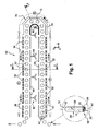
- FIG. 1 there is shown an embodiment of a heat-treatment furnace 10 of preforms, in particular plastic or thermoplastic preforms, such as polyethylene terephthalate (PET).
- preforms in particular plastic or thermoplastic preforms, such as polyethylene terephthalate (PET).
- PET polyethylene terephthalate
- the figure 1 is a detail view of a preform 12 for the manufacture of a hollow body container, such as a bottle, a bottle etc., especially by blow molding or by stretch blow molding.
- preform denotes in the following description both the initial preform obtained by plastic injection and used in manufacturing processes of a container with a single blowing step leading directly to the final container that the intermediate container in the case of multi-step blowing processes.
- the preforms 12 are generally made according to an injection molding process and are, for example, molded in a place other than that in which the container manufacturing installation is located.
- a preform 12 generally has a generally tubular body 14 of cylindrical section along a horizontal sectional plane, said body 14 extending vertically along a main axis A1, here in a position called "neck down".
- the preform 12 is closed at its upper end by a substantially hemispherical bottom 16, which corresponds to the upper part of the body of the preform intended to form the bottom of the container.
- the preform 12 is open at its lower end which is shaped into a neck 18 which already has the final shape of the neck or neck of the container.
- the preform 12 comprises at the junction between the body 14 and the neck 18, a flange 20 which extends radially outwardly projecting from the body 14 and the neck 18.
- the neck 18 defines an annular opening 22 centered on the axis A1 and has on its external surface a thread 24 intended to allow the subsequent introduction of screw closure means of the container, such as a plug (not shown) .
- the main parts of the preform 12 considered as part of the sterilization are respectively the surface of the inner wall 26, the outer surface 28 of the body 14 extending vertically from the bottom 16 to the collar 20 of the neck 18.
- the furnace 10 comprises a transport device 30 for successively conveying the preforms 12 from upstream to downstream and which is provided with means ensuring the rotation on itself of each preform around its vertical axis A1.
- the preforms 12 thus move from the inlet of the oven 10 to the exit in the direction of the arrows "d" represented on the figure 1 and travel from upstream to downstream the different zones that the furnace 10 comprises at a speed of displacement V while simultaneously rotating each on itself at a determined rotational speed.
- the furnace 10 successively comprises a first zone A, referred to as a penetration heating zone, a second intermediate zone B, called a timing zone, and a third heating zone C; final heating, which are respectively marked as a dotted line on the figure 1 .
- the first penetration heating zone A comprises first heating means 32 emitting infrared radiation IR1 which is intended to preheat the body 14 of each preform 12 to a first set temperature TC1.
- the first set temperature TC1 corresponding here to the preheating temperature is between 50 ° C and 80 ° C, for example equal to 70 ° C.
- the second intermediate zone B of delay is interposed in the path of the preforms 12 between the first heating zone A and the third heating zone C.
- the second zone B is traversed by each preform 12 in a determined time interval ⁇ t, which is in particular a function of the speed of displacement V of the preforms 12 entrained by the transport device 30.
- the time interval ⁇ t is for example between 2 and 15 seconds, depending on the rate of the machine, generally of the order of 5 seconds.
- the delay in the second zone B, between the first and third heating zones, is intended to allow a homogeneous distribution throughout the body 14 of the heat transmitted by the first heating means 32.
- the third distribution heating zone C includes second heating means 34 emitting infrared radiation IR2 which is intended to heat the body 14 of each preform 12 to a second setpoint temperature TC2.
- the second set temperature TC2 here corresponds to the heating temperature is between 80 ° C and 130 ° C, generally of the order of 90 ° C to 110 ° C.
- the heating temperature is determined in particular according to the characteristics of the preform 12 such as the material, the thickness of the body 14, etc. and the container.
- the first heating means 32 and / or the second heating means 34 consist, for example, of infrared lamps, generally tube-shaped, which in operating position in the heating zones A and C extend longitudinally and are mounted one above the other in racks (not shown).
- the transport device 30 of the preforms 12 comprises support means 36 on which the preforms 12 are mounted in the "neck down" position, ie the bottom 16 directed upwards, and which are provided with guide means 38, by example with rollers, engaged in raceways 40 additional shaped "U".
- the support means 36 of the transport device 30 comprise gripping means 42 of the neck 18 of each preform 12, the gripping means 42 advantageously comprising an inner core (not shown) which extends vertically upwards. way to penetrate axially along the axis A1 inside the opening 22 delimited by the neck 18.
- the furnace 10 comprises protection means 44, for example in the form of a rail, forming covers intended to provide thermal protection for the neck 18 of each preform 12 with respect to the infrared rays.
- the neck 18 of each preform 12 having the final shape of that of the neck or neck of the final container, it must not be exposed to the infrared radiation of the heating means 32, 34 of the oven to avoid any risk of deformation particularly liable to compromise subsequent after filling, the closing operation of the container.
- the protection means 44 extend horizontally above the supports 36 delimiting between them a passage calibrated so as to respectively allow the body 14 of the preform 12 extending vertically above being heated and the neck 18 extending below being protected on the contrary.
- the protection means 44 are cooled by associated cooling means (not shown).
- the first and third heating zones A and C of the furnace 10 extend vertically above the means of protection 44 of the necks 18 and respectively comprise an outer wall 46 and an inner wall 48 between which, transported by the device 30, scroll the body 14 of the preforms 12 to be heated.
- the outer wall 46 preferably comprises insulating panels associated with the infrared heating lamps 32 or 34 which are superimposed vertically one above the other, while the inner wall 48 opposite consists of reflective panels capable of reflecting the infrared rays emitted by the lamps 32, 34 towards the preforms.
- each heating lamp 32, 34 can be selectively adjusted in the transverse direction, in particular in the third heating zone C to establish a determined heating profile by varying the distance between each of the lamps second heating means 34 and the body 14 as the bottom 16 of the preforms 12 facing each other.
- the furnace 10 comprises a so-called superficial cooling device 50 of the body 14 of the preforms 12 which is obtained by circulating a flow of air F around the preforms as illustrated by arrows on the figure 2 .
- the cooling air circulation device 50 comprises filtration means 52 intended to filter the flow of cooling air circulated in the oven 10 so as to purify the air and prevent any contamination of the preforms with germs, etc.
- the cooling air circulated in the oven 10 is constituted by sterile air or having a high degree of decontamination.
- the device 50 comprises thermoregulation means (not shown) of the air temperature.
- the oven 10 is provided with ventilation holes to allow the passage of the air flow F blown through propeller means 54 intended to promote homogeneous heating throughout the thickness of the preform 12, in particular without overheating the surface material layer of the outer surface 28 of the body 14 and the bottom 16.
- the air makes it possible to evacuate the convection heat caused by the heating means 32, 34 and to promote the penetration of the infrared radiation IR1, IR2 emitted into the thickness of the material constituting the preform 12.
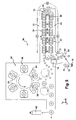
- the figure 5 schematically represents an installation 56 for the manufacture of sterile containers, such as bottles, from thermoplastic preforms 12 of the type of that shown in FIG. figure 1 .
- Such an installation 56 mainly comprises, according to the direction of movement of the preforms 12 from upstream to downstream, a supply device 58, a thermal conditioning station 60 comprising at least one oven 10 and its transport device 30, a molding station 62.
- the oven 10 of the station 60 is intended to heat the body 14 of each preform to allow its molding at the molding station 62 downstream.
- the heating means 32 and 34 of the furnace 10 thus provide a first function of heating the preforms 12 to soften them, according to a determined heating profile, by bringing to a molding temperature Tm function of the constituent material of the preform.
- the molding temperature Tm is about 100 ° C.
- the second setpoint temperature TC2 of the second heating means 34 is equal to the molding temperature Tm, which is greater than the glass transition temperature Tg of the constituent material of the preform 12.
- the molding station 62 comprises at least one mold 64 and a blowing device 66 associated to convert the preform 12 into a hollow body container 68, here a bottle as shown in detail in FIG. figure 5 at the exit of station 62 of installation 56.
- the installation 56 comprises downstream of the molding station 62 blow-molding each preform 12 into a bottle 68, a filling station and a sealing station (not shown).
- the supply device 58 is arranged at the input of the installation 56 that it is intended to supply continuous preforms 12.
- Such a feed device 58 comprises for example a hopper (not shown) in which are poured in bulk preforms 12 which are taken one by one at the base of the hopper to be routed one after the other in position " collar up ".
- the preforms 12 are preferably conveyed by gravity by means of an inclined slide 70, the slide being formed by two parallel rails spaced apart from each other so as to pass vertically body 14 preforms 12 but on which each preform 12 rests through its collar 20.
- Prehensile means capable of individually gripping each preform 12 are for example arranged at the end of the slideway 70 and constituted by a loading wheel 72.
- the loading wheel 72 is intended to deliver the preforms 12 at the inlet of the thermal conditioning oven where they are supported by the transport device 30.
- the preforms 12 are conveyed through the furnace 10 by the transport device 30 in an opposite position "neck down", there is provided turning means (not shown) preforms between the wheel 72 and the supports 36 to inner core of the device 30.
- the installation 56 thus comprises a sterilization station 74 which is for example disposed above the loading wheel 72, upstream of the overturning means of the preforms 12 and the inlet of the furnace 10.
- the sterilization station 74 (not shown in detail) comprises a sterilizing product spraying device provided with at least one nozzle capable of projecting, in the form of a jet of steam, a flow of sterilizing product towards the sterilant. opening 22 of the neck 18 of each preform 12, whose temperature T0 is less than the condensation temperature Tc of the sterilizing product.
- condensation is deposited on at least the inner wall 26 of the preform a substantially uniform sterilizing product mist film which is intended to sterilize the inner wall 26.
- the activation temperature Ta of hydrogen peroxide H 2 O 2 is about seventy degrees Celsius (70 ° C).
- the sterilizing product H 2 O 2 is activated as soon as the preform 12 enters the first preheating zone A of the oven 10 so that the inner wall 26 of the preform 12 is sterilized.
- the first infrared heating means 32 of the oven 10 are intended to heat the body 14 of the preform 12 to the first set temperature TC1, which is advantageously greater than or equal to the activation temperature Ta.
- the second infrared heating means 34 of the third heating zone C of the oven 10 are intended to heat the preform 12 to the second set temperature TC2 equal to the molding temperature Tm (from 90 to 130 ° C.) which is greater than the evaporation temperature Te of a sterilizing product, such as H 2 O 2 .
- the sterilizing product H 2 O 2
- the sterilizing product is automatically removed by evaporation during heating in zone C, so that the final container 68 obtained has at most a few trace amounts of sterilizing product in accordance with the legal requirements in force.
- the heating means 32 and 34 of the oven 10 thus provide, in addition to a first conventional heating function for molding, a second function of thermally activating the sterilizing product by heating so as to sterilize at least the inner wall 26 of the preform 12 and then removing by evaporation said previously activated product to remove almost all traces in the final container 68.
- the inner wall 26 of the preform 12 is in contact with the sterilizing product mist film deposited by condensation and which is activated as soon as it enters the oven 10 during a period of time, called internal decontamination, which corresponds at least to the period of time set by a preform to successively traverse the first zone A.
- the decontamination of the inner wall 26 may continue on all or part of the second intermediate zone B, before the sterilizing product film gradually evaporates in the third zone C.
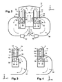
- the oven 10 is characterized in that it comprises the first heating means 32, the sterilization means 76 which are arranged in the second intermediate zone B of delay and which are able to emit UV ultraviolet rays and the second heating means 34 so as to sterilize at least the outer surface 28 of the body 18 of the preform 12 to the determined degree of decontamination.
- the sterilization process used in an oven 10 according to the invention is capable of sterilizing at least the outer surface 28 of the body 14 of the preform 12 to a determined degree of decontamination.
- such a sterilization process is therefore likely to be implemented in an oven 10 such as the oven 10 of a thermal conditioning station 60 of a facility 56 for manufacturing sterile containers from preforms 12 of materials.
- thermoplastics for blow-molding or stretch blow molding are examples of materials.
- the UV ultraviolet rays emitted by the sterilization means 76 in the second intermediate zone B of delay sterilize the air of the cooling air flow circulating around the preforms 12.
- the oven 10 comprises in the second intermediate zone B timing UV ultraviolet sterilization means 76 which consist of UV lamps 78 UV and associated reflecting means 80, such as reflectors.
- the reflectors 80 are arranged inside the oven 10 vis-à-vis the ultraviolet UV lamps 78 so as to selectively reflect UV ultraviolet rays emitted towards the preforms 12.
- the ultraviolet sterilization means 76 formed by the ultraviolet UV lamps 78 and by the reflecting means 80 are here globally arranged "horseshoe" according to the path of the preforms 12 in the second zone B and on either side of the latter which thus scroll at the speed V and rotating on itself between the UV lamps 78 and the reflectors 80.
- the reflectors 80 arranged inside are replaced by a wall provided with ultraviolet UV lamps 78 so that the second intermediate zone B for delaying the oven 10 comprises additional ultraviolet UV emission means for sterilizing the preforms 12 .
- such a variant makes it possible to increase overall the ultraviolet UV radiation emitted and therefore the quantity of radiation received by the external surface 28 of the body 14 and by the neck 18 of the preform 12 so as to increase the final degree of decontamination, for the same speed V of displacement of the preforms 12.
- the sterilization means 76 make it possible to maintain a high degree of decontamination even when the speed V increasing the lapse of time ⁇ t decreases.
- the lapse of time ⁇ t corresponds to the exposure time of the outer surface 28 of the body 14 and the neck 18 of the preform 12 to UV ultraviolet rays.
- the average temperature in the second zone B timing is of the order of 40 to 50 ° C so that the protection means 44 of the necks 18 are advantageously removed.
- the sterilization means 76 such as the lamps 78 and / or the reflectors 80 are arranged so that the neck 18 also is irradiated with UV ultraviolet rays.
- the lamps 78 of the sterilization means 76 are constituted by lamps of the standard type, for example in the form of a tube, which have a surrounding temperature of the order of 50 ° C. in the second intermediate zone B reliable operation and duration of normal life.
- the transport device 30 comprises the gripping means 42 of the neck 18 of each preform 12 provided with the inner core penetrating axially inside the opening 22 of the neck 18 of the preform 12 so that the external surface of the neck 18 of the preform 12 is entirely irradiated by the UV ultraviolet rays emitted by the sterilization means 76.
- the degree of decontamination obtained is relatively low, generally less than 0.5 Log.
- the degree of decontamination obtained is then between 2 Log and 3 Log, by example of the order of 2.5 Log.
- the ultraviolet UV irradiation time of the preforms 12 advantageously corresponds to the predetermined time interval ⁇ t set by each preform 12 to travel through the second delay zone B of a given furnace, each preform 12 being driven through the furnace 10 by the transport device 30 at a determined displacement speed V which is a function of the type of furnace and applications.
- the tests carried out have demonstrated that by consecutively carrying out a UV ultraviolet sterilization step and then a thermal sterilization step by infrared or conversely a step of infrared thermal sterilization then a UV ultraviolet sterilization step, the degree decontamination obtained overall was similar to that obtained previously with the only step of UV ultraviolet sterilization, that is to say of the order of 2.5 Log.
- the combination of the three successive stages used in an oven 10 according to the invention has a degree of decontamination that is as unexpected as it is particularly high.
- the implementation of the method in an oven 10 according to the invention comprising the sterilization means 76 is carried out at least in the successive decontamination steps described above to sterilize at least the outer wall 28 of the body 14 of the preform 12.
- the heating means 32 and 34 of the oven 10 still provide a third function of promoting the decontamination of the preform 12 by combining the sterilizing effects of infrared heating and ultraviolet UV irradiation to obtain a final degree of particularly high decontamination.
- the final degree of decontamination of the external surface 28 of the body 14 is obtained solely by the combination of these three sterilization steps which, carried out consecutively, will successively make it possible to eliminate at least a first part of the seeds, bacteria or spores, etc. . present on the outer surface 28 of the body 14 of the preform 12 which are destroyed and / or altered by the heat of the infrared ray IR1, and which therefore, at the very least, weakened, have an increased vulnerability thanks to which the ultraviolet UV goes destroy or alter other germs, etc. additional, the majority of germs etc. remaining on the outer surface 28 of the body 14 of the preform 12 are then destroyed by the strong heat of infrared rays IR2.
- the sterilization process comprises a preliminary sterilization step of the inner wall 24 of the preform 12 which, prior to the first preheating step, consists in projecting a stream of sterilizing product into the form of a jet of steam. opening 22 of the neck 18 of each preform 12 at a temperature T0 lower than the condensation temperature Tc of the sterilizing product so as to cause, on the inner wall 24 of the preform 12, the deposition by condensation of a vapor film substantially uniform sterilizing product.
- the uniform condensed sterilant vapor misting film which is then thermally activated by the first heating means 32 of the oven, then evaporated off by the second heating means 34, sterilizes the inner wall 26 with a degree of decontamination. at least 3 Logs
- preforms 12 sterilized and thermally conditioned in an oven 10 according to the invention it is possible from preforms 12 sterilized and thermally conditioned in an oven 10 according to the invention to produce sterile containers having a particularly high final degree of decontamination and that both on the inner wall 26 of the preform 12 only on the outer surface 28 of the body 14 of the preform 12.
- the second function of the heating means 32 and 34 of the oven 10 is to thermally activate and then remove by evaporation the sterilant product deposited by condensation.
- the first preheating temperature TC1 is therefore greater than or equal to the activation temperature Ta of the sterilizing product so as to sterilize the inner wall 26 of the preform 12 while the second heating temperature TC2 is greater than the temperature of Te evaporation of the sterilizing product so as to remove by evaporation the sterilizing product previously activated thermally.
- the sterilization method according to the invention can be implemented in a particularly simple, reliable and economical manner, in particular in a sterile container manufacturing facility of the type described and represented in FIG. figure 5 .
- the infrared radiation of the first and second heating means 32, 34 advantageously have a triple action, namely heating the preform 12 for blow-molding or stretch-blow molding into sterile hollow containers, sterilization (or decontamination ) of the inner wall 26 by activation and evaporation of the sterilizing product and, in combination with UV ultraviolet irradiation, so-called thermal sterilization of the outer surface 28 of the body 14.
Abstract
Description
L'invention concerne un four et une installation pour la fabrication de récipients stériles à partir de préformes en matière thermoplastiques décontaminées.The invention relates to an oven and an installation for the manufacture of sterile containers from decontaminated thermoplastic preforms.
La présente invention concerne d'une façon générale le domaine de la stérilisation (ou décontamination) des préformes en matière thermoplastique, notamment en Polyéthylènetéréphtalate (PET), qui sont destinées à la fabrication de récipients, tels que des bouteilles, flacons ou analogues, par un processus de soufflage ou d'étirage-soufflage d'une préforme préalablement conditionnée thermiquement dans un four.The present invention relates generally to the field of the sterilization (or decontamination) of thermoplastic preforms, in particular polyethylene terephthalate (PET), which are intended for the manufacture of containers, such as bottles, flasks or the like, by a blowing or stretch-blow molding process of a preform previously conditioned thermally in an oven.
L'invention concerne, selon un de ses aspects, un four de conditionnement thermique de préformes en matière thermoplastique destinées à la fabrication de récipients à corps creux par soufflage ou étirage-soufflage, comportant un dispositif de transport des préformes qui sont mises en rotation sur elle-même et convoyées successivement entre au moins :
- une première zone, dite de chauffage de pénétration, comportant des premiers moyens de chauffage par rayonnement infrarouge destinés à préchauffer le corps de chaque préforme jusqu'à une première température de consigne ;
- une deuxième zone intermédiaire, dite de temporisation qui, interposée sur le trajet des préformes entre la première zone de chauffage et une troisième zone de chauffage, est parcourue par chaque préforme en un laps de temps déterminé ;
- la troisième zone, dite de chauffage de distribution, comportant des seconds moyens de chauffage par rayonnement infrarouge destinés à chauffer le corps de chaque préforme, selon un profil de chauffe déterminé, jusqu'à une deuxième température de consigne.
- a first zone, referred to as a penetration heating zone, comprising first infrared heating means for preheating the body of each preform to a first setpoint temperature;
- a second intermediate zone, called delay zone which, interposed on the path of the preforms between the first heating zone and a third heating zone, is traversed by each preform in a predetermined period of time;
- the third zone, called distribution heating zone, comprising second infrared heating means for heating the body of each preform, according to a determined heating profile, to a second set temperature.
On connaît de nombreux fours de ce type en particulier pour le chauffage par rayonnement infrarouge d'une préforme afin de la conditionner thermiquement en vue de son moulage, c'est à dire sa transformation par soufflage en un récipient, par exemple une bouteille, un tel four étant alors intégré dans une installation de fabrication dont il constitue l'un des principaux postes.Many furnaces of this type are known, in particular for the heating by infrared radiation of a preform in order to thermally condition it for molding, that is to say its transformation by blowing into a container, for example a bottle, a such oven is then integrated into a manufacturing facility of which it is one of the main positions.
Les documents
De manière connue, les préformes destinées à la fabrication de récipients stériles ou décontaminés dans une installation sont avantageusement traitées en début du processus de fabrication des récipients, plutôt qu'en fin de processus de fabrication une fois le récipient obtenu par soufflage, car on réduit ainsi la quantité de produit stérilisant utilisée qui est en partie fonction de la surface à décontaminer.In known manner, the preforms intended for the manufacture of sterile or decontaminated containers in an installation are advantageously treated at the beginning of the manufacturing process of the containers, rather than at the end of the manufacturing process once the container has been blown, since it reduces thus the amount of sterilizing product used which is partly a function of the surface to be decontaminated.
L'invention concerne, selon un autre de ses aspects, une installation pour la fabrication de récipients stériles, à partir d'une préforme en matière thermoplastique décontaminée, qui comporte généralement au moins :
- un dispositif d'alimentation en préformes ;
- un poste de conditionnement thermique comportant un dispositif de transport de préformes qui sont mises en rotation sur elle-même et convoyées à travers au moins un four destiné à chauffer chaque préforme en vue de son moulage ; et
- un poste de moulage comportant au moins un moule et un dispositif de soufflage associé destiné à transformer chaque préforme en un récipient à corps creux.
- a feed device in preforms;
- a thermal conditioning station comprising a device for transporting preforms which are rotated on itself and conveyed through at least one furnace for heating each preform for molding; and
- a molding station comprising at least one mold and an associated blowing device for transforming each preform into a hollow body container.
On connaît de nombreuses installations pour la fabrication de récipients stériles de ce type par soufflage ou étirage-soufflage et comportant de plus des moyens de stérilisation de ces préformes, par exemple par voie chimique en procédant notamment au mouillage des surfaces à décontaminer par trempage dans une solution stérilisante, telle que du peroxyde d'hydrogène (H2O2).Many installations are known for the manufacture of sterile containers of this type by blow molding or stretch-blow molding and furthermore comprising means for sterilizing these preforms, for example chemically by proceeding in particular wetting the surfaces to decontaminate by soaking in a sterilizing solution, such as hydrogen peroxide (H 2 O 2 ).
Le document
L'installation représentée à la
Dans cette installation, les préformes sont traitées par des moyens de stérilisation, en amont du four de chauffage de la préforme, de manière à décontaminer la surface cylindrique de la paroi interne de la préforme.In this installation, the preforms are treated by sterilization means, upstream of the preform heating furnace, so as to decontaminate the cylindrical surface of the inner wall of the preform.
La paroi interne de la préforme correspond à la paroi interne du récipient à corps creux destiné à être fabriqué par soufflage à partir de cette préforme de sorte que cette paroi interne de la préforme délimite le volume intérieur du récipient destiné à être rempli ultérieurement, par exemple par un liquide donné dans le cas d'une bouteille ou d'un flacon.The inner wall of the preform corresponds to the inner wall of the hollow body container intended to be manufactured by blowing from this preform so that the inner wall of the preform defines the interior volume of the container to be filled later, for example by a given liquid in the case of a bottle or a bottle.
Les moyens de stérilisation décrits dans ce document comprennent notamment un produit de stérilisation, tel qu'une solution de peroxyde d'hydrogène (H2O2), qui est activé thermiquement par la chaleur des moyens de chauffage du four, avant d'être éliminé par évaporation.The sterilization means described in this document comprise in particular a sterilization product, such as a solution of hydrogen peroxide (H 2 O 2 ), which is thermally activated by the heat of the oven heating means, before being eliminated by evaporation.
Les moyens de stérilisation comportent pour ce faire un pulvérisateur constitué par un pistolet de vaporisation permettant de mouiller l'intérieur des préformes avec du produit de stérilisation "froid", c'est-à-dire n'ayant pas été préalablement chauffé et se trouvant donc à l'état liquide.The sterilization means comprise for this purpose a spray consisting of a spray gun for wetting the inside of the preforms with the product of sterilization "cold", that is to say having not been previously heated and therefore being in the liquid state.
Le pistolet est typiquement un pistolet de type bi-fluide comportant une buse de liquide et une buse d'air formant un ensemble de projection circulaire qui est susceptible d'être placé au-dessus du trajet des préformes de manière à pulvériser un brouillard de produit de stérilisation.The gun is typically a bi-fluid type gun having a liquid nozzle and an air nozzle forming a circular projection assembly which is capable of being placed above the path of the preforms so as to spray a product mist. sterilization.
Le brouillard de produit de stérilisation est formé d'un nuage de gouttelettes qui est projeté par le pistolet vers l'intérieur de la préforme suivant un écoulement de type turbulent.The mist of sterilization product is formed of a cloud of droplets which is projected by the gun towards the inside of the preform according to a turbulent type flow.
On a constaté qu'un tel écoulement turbulent de produit de stérilisation à l'intérieur de la préforme conduit à la formation d'un ensemble de gouttelettes qui ne sont pas reparties de manière homogène sur la paroi interne de la préforme.It has been found that such a turbulent flow of sterilization product inside the preform leads to the formation of a set of droplets which are not homogeneously distributed on the inner wall of the preform.
En effet, l'utilisation d'un pistolet de pulvérisation est notamment caractérisé par un débit important de produit stérilisant qui est obtenu en comprimant un gaz, tel que de l'air comprimé à des pressions d'environ 2 à 3 bars, de sorte qu'il produit un écoulement turbulent.Indeed, the use of a spray gun is characterized in particular by a high flow of sterilizing product which is obtained by compressing a gas, such as compressed air at pressures of about 2 to 3 bars, so it produces a turbulent flow.
Or, l'écoulement turbulent conduit au dépôt non homogène de gouttelettes résiduelles de produit stérilisant sur les parois internes des préformes. De plus, les gouttelettes de produit stérilisant forment un excédent qui n'est pas entièrement vaporisé lors du chauffage.However, the turbulent flow leads to inhomogeneous deposition of residual droplets of sterilizing product on the inner walls of the preforms. In addition, the droplets of sterilant product form a surplus that is not fully vaporized during heating.
Ces gouttelettes de produit stérilisant provoquent donc d'une part localement une attaque chimique du matériau de la préforme, généralement en polyéthylène téréphtalate (PET), et, d'autre part, lors du chauffage des préformes, produisent un effet loupe sur les rayonnements thermiques de chauffage, ce qui provoque l'apparition de taches sur les parois des récipients, tels que les bouteilles, issues des préformes traitées.These droplets of sterilizing product thus cause, on the one hand, a chemical attack of the preform material, generally made of polyethylene terephthalate (PET), and, on the other hand, during the heating of the preforms, produce a magnifying effect on the thermal radiation. heating, which causes the appearance of stains on the walls of containers, such as bottles, from processed preforms.
L'apparition de telles taches sur les parois des bouteilles, est un défaut d'aspect du produit, qui est encore parfois appelé "aspect peau d'orange".The appearance of such spots on the walls of bottles, is a lack of appearance of the product, which is still sometimes called "orange peel appearance".
De plus, la quantité de solution de stérilisation susceptible d'être utilisée est limitée en raison des obligations légales d'élimination de la solution de stérilisation dont il ne doit subsister tout au plus que de très infimes traces sur le récipient stérilisé et cela afin notamment que le liquide destiné à remplir le récipient ne présente pas une quantité de solution de stérilisation supérieure au taux légal admis.In addition, the amount of sterilization solution that can be used is limited because of the legal obligations to eliminate the sterilization solution of which there must remain at most only very small traces on the sterilized container and this in particular that the liquid intended to fill the container does not present a quantity of sterilization solution greater than the authorized legal rate.
Par conséquent, les récipients fabriqués conformément à ce procédé ne donnent pas entière satisfaction et, de surcroît, ne présentent pas un degré de décontamination suffisant par rapport au niveau de stérilité requis pour certaines applications industrielles.Therefore, the containers manufactured according to this method are not entirely satisfactory and, moreover, do not have a sufficient degree of decontamination relative to the level of sterility required for certain industrial applications.
En effet, la décontamination opérée dans l'installation selon ce procédé concerne uniquement la paroi interne de la préforme. Cependant, la surface externe du corps de la préforme comporte de manière analogue des germes, bactéries ou spores qui peuvent contaminer les préformes (ou les récipients) ainsi que l'installation de fabrication en général.Indeed, the decontamination performed in the installation according to this method only concerns the inner wall of the preform. However, the outer surface of the body of the preform similarly comprises germs, bacteria or spores that can contaminate the preforms (or containers) and the manufacturing facility in general.
Or, les germes, bactéries etc. présents sur la surface externe du corps de la préforme sont susceptibles de se propager dans l'installation, en utilisant notamment comme vecteur le flux d'air de refroidissement circulant autour des préformes dans le four ou encore en contaminant la surface des moules du poste de soufflage de l'installation.Or, germs, bacteria etc. present on the outer surface of the body of the preform are likely to propagate in the installation, using in particular as a vector the flow of cooling air circulating around the preforms in the furnace or by contaminating the surface of the molds of the station. blowing the installation.
Il existe par conséquent un risque de contamination, encore parfois appelé "risque de contamination croisée", selon lequel la présence de germes, etc. sur la surface externe de la préforme est susceptible d'engendrer des contaminations pouvant affecter la stérilité, du récipient final ou de lots entiers de récipients, notamment la stérilité interne.There is therefore a risk of contamination, sometimes referred to as the "risk of cross-contamination", according to which the presence of germs, etc. on the outer surface of the preform is likely to cause contaminations that can affect sterility, the final container or whole batches of containers, including internal sterility.
C'est l'une des raisons pour lesquelles, des solutions permettant tout particulièrement une décontamination efficace de la surface externe du corps de chaque préforme ont été recherchées.This is one of the reasons why solutions particularly allowing effective decontamination of the outer surface of the body of each preform have been sought.
Une solution possible consiste à traiter la surface externe du corps de la préforme par voie chimique de manière analogue à la paroi interne, c'est-à-dire par pulvérisation, en amont du four de conditionnement thermique, d'une solution de stérilisation, telle que de peroxyde d'hydrogène (H2O2), sur la surface externe du corps de la préforme.One possible solution consists in treating the external surface of the body of the preform chemically in a manner analogous to the internal wall, that is to say by spraying, upstream of the thermal conditioning oven, a sterilization solution. such as hydrogen peroxide (H 2 O 2 ), on the outer surface of the body of the preform.
Des essais ont toutefois démontré que le flux d'air de refroidissement circulant dans le four provoque l'élimination quasi systématique et immédiate de la majeure partie de la solution de stérilisation appliquée sur la surface externe et cela avant que la solution stérilisante n'ait pu être activée thermiquement par les moyens de chauffage, de sorte que la décontamination de la surface externe du corps de la préforme ainsi obtenue est généralement très faible et donc insuffisante pour atteindre un degré final de décontamination élevé.However, tests have shown that the flow of cooling air flowing in the furnace causes almost systematic elimination of the bulk of the sterilization solution applied to the external surface, and this before the sterilizing solution has been able to to be activated thermally by the heating means, so that the decontamination of the outer surface of the body of the preform thus obtained is generally very small and therefore insufficient to achieve a final degree of high decontamination.
L'invention vise à remédier à ces inconvénients en proposant, un nouveau four permettant notamment, selon un procédé de stérilisation global d'une préforme, de fabriquer dans une installation de fabrication de récipients stériles par soufflage ou par étirage-soufflage de préformes, de tels récipients stériles de manière simple, fiable et économique à partir de préformes intégralement stérilisées ou décontaminées, tant à l'intérieur qu'à l'extérieur.The aim of the invention is to overcome these drawbacks by proposing, in particular, a new furnace which makes it possible, in accordance with a process for overall sterilization of a preform, to manufacture sterile containers by blowing or by stretch-blow molding of preforms, such sterile containers simply, reliably and economically from fully sterilized or decontaminated preforms, both indoors and outdoors.
L'invention vise tout particulièrement, mais non exclusivement, la stérilisation de la surface externe du corps d'une préforme, c'est-à-dire l'abaissement du taux de contamination par des germes, bactéries ou spores etc. de cette surface en vue de limiter tout particulièrement le risque de contamination croisée.The invention is particularly, but not exclusively, aimed at sterilization of the external surface of the body of a preform, that is to say the lowering of the contamination rate by germs, bacteria or spores, etc. of this surface in order to particularly limit the risk of cross-contamination.
Dans ce but, l'invention propose un four de conditionnement thermique de préformes en matière thermoplastique, notamment destiné à équiper une installation de fabrication de récipients stériles par soufflage ou par étirage-souffage, du type comportant un dispositif de transport des préformes qui sont mises en rotation sur elle-même et convoyées successivement entre au moins :
- une première zone, dite de chauffage de pénétration, comportant des premiers moyens de chauffage par rayonnement infrarouge destinés à préchauffer le corps de chaque préforme jusqu'à une première température de consigne ;
- une deuxième zone intermédiaire, dite de temporisation qui, interposée sur le trajet des préformes entre la première zone de chauffage et une troisième zone de chauffage, est parcourue par chaque préforme en un laps de temps déterminé ;
- la troisième zone, dite de chauffage de distribution, comportant des seconds moyens de chauffage par rayonnement infrarouge destinés à chauffer le corps de chaque préforme, selon un profil de chauffe déterminé, jusqu'à une deuxième température de consigne,
- a first zone, referred to as a penetration heating zone, comprising first infrared heating means for preheating the body of each preform to a first setpoint temperature;
- a second intermediate zone, called delay zone which, interposed on the path of the preforms between the first heating zone and a third heating zone, is traversed by each preform in a predetermined period of time;
- the third zone, called the distribution heating zone, comprising second infrared radiation heating means for heating the body of each preform, according to a determined heating profile, to a second set temperature,
Selon d'autres caractéristiques du four selon l'invention :
- le four comporte des moyens réfléchissants, tels que des réflecteurs, qui sont agencés dans la deuxième zone intermédiaire de temporisation en vis-à-vis des moyens de stérilisation par ultraviolets, tels que des lampes, de manière à réfléchir sélectivement les rayons ultraviolets émis en direction des préformes circulant entre les moyens de stérilisation et les moyens réfléchissants ;
- le four comporte un dispositif de refroidissement des préformes par circulation d'un flux d'air autour des préformes,
- le dispositif de transport comporte des moyens de préhension du col de chaque préforme comportant au moins un noyau interne qui pénètre axialement à l'intérieur du col de la préforme de manière que les rayons ultraviolets émis par les moyens de stérilisation irradient intégralement le col de la préforme.
- the furnace comprises reflecting means, such as reflectors, which are arranged in the second intermediate zone of delay vis-à-vis the ultraviolet sterilization means, such as lamps, so as to selectively reflect the ultraviolet rays emitted direction of the preforms circulating between the sterilization means and the reflecting means;
- the oven comprises a device for cooling the preforms by circulating a flow of air around the preforms,
- the transport device comprises means for gripping the neck of each preform comprising at least one inner core which penetrates axially inside the neck of the preform so that the ultraviolet rays emitted by the sterilization means radiate completely the neck of the preform. preform.
L'invention propose encore une installation du type décrit précédemment pour la fabrication de récipients stériles à partir d'une préforme en matière thermoplastique décontaminée suivant le procédé de stérilisation, caractérisée en ce que l'installation comporte un four de conditionnement thermique comportant :
- des premiers moyens de chauffage destinés à décontaminer au moins la surface externe du corps de la préforme en préchauffant le corps de chaque préforme jusqu'à une première température de consigne ;
- des moyens de stérilisation par émission de rayons ultraviolets destinés à décontaminer au moins la surface externe du corps de la préforme par irradiation de la la préforme (12) exposée pendant un laps de temps (Δt) déterminé aux rayons ultraviolets (UV) émis par les moyens de stérilisation (76) ; et
- des seconds moyens de chauffage destinés à décontaminer au moins la surface externe du corps de la préforme en chauffant le corps de chaque préforme, jusqu'à une deuxième température de consigne,
de manière à stériliser au moins la surface externe du corps de la préforme jusqu'à un degré de décontamination déterminé.
- first heating means for decontaminating at least the outer surface of the body of the preform by preheating the body of each preform to a first set temperature;
- ultraviolet radiation sterilization means for decontaminating at least the outer surface of the body of the preform by irradiation of the exposed preform (12) for a specified period of time (Δt) to the ultraviolet (UV) rays emitted by the sterilization means (76); and
- second heating means for decontaminating at least the outer surface of the body of the preform by heating the body of each preform to a second set temperature,
so as to sterilize at least the outer surface of the body of the preform to a determined degree of decontamination.
Avantageusement, l'installation comporte, en amont du four de conditionnement thermique, un poste de stérilisation comportant un dispositif de projection de produit stérilisant pourvus d'au moins une buse apte à projeter, sous forme d'un jet de vapeur, un flux de produit stérilisant vers l'ouverture du col de chaque préforme, dont la température est inférieure à la température de condensation du produit stérilisant, de manière à déposer par condensation sur au moins la paroi interne de la préforme un film de buée de produit stérilisant sensiblement uniforme destiné à stériliser la paroi interne.Advantageously, the installation comprises, upstream of the thermal conditioning oven, a sterilization station comprising a sterilizing product spraying device provided with at least one nozzle capable of projecting, in the form of a jet of steam, a stream of sterilizing product towards the opening of the neck of each preform, whose temperature is lower than the condensation temperature of the sterilizing product, so as to deposit by condensation on at least the inner wall of the preform a substantially uniform sterilizing product mist film for sterilizing the inner wall.
Avantageusement, la première température de préchauffage et/ou la deuxième température de chauffage du corps de la préforme sont supérieures ou égales à la température d'activation du produit stérilisant de manière à activer par chauffage le produit stérilisant pour stériliser la paroi interne de la préforme.Advantageously, the first preheating temperature and / or the second heating temperature of the body of the preform are greater than or equal to the activation temperature of the sterilizing product so as to activate by heating the sterilizing product to sterilize the inner wall of the preform. .
Avantageusement, la première température de préchauffage et/ou la deuxième température de chauffage du corps de la préforme sont supérieures à la température d'évaporation du produit stérilisant de manière à éliminer par évaporation le produit stérilisant activé par chauffage.Advantageously, the first preheating temperature and / or the second heating temperature of the body of the preform are greater than the evaporation temperature of the sterilizing product so as to evaporate the heated sterilant product.
D'une manière générale, on rappellera que dans le domaine visé par l'invention, le niveau de stérilité d'une préforme
ou d'un récipient s'apprécie en fonction du nombre de germes, bactéries ou spores, de sorte que l'on se réfère le plus souvent au degré de décontamination obtenu.In general, it will be recalled that in the field targeted by the invention, the sterility level of a preform
or of a container is appraised according to the number of germs, bacteria or spores, so that one refers more often to the degree of decontamination obtained.
Le niveau de stérilité ou degré de décontamination est déterminé par comptage de la quantité de germes, etc. qui sont dénombrés après des opérations de lavage, de filtration et de mise en culture et il est généralement exprimé en "Log" en fonction de la réduction logarithmique du nombre de germes, etc.The level of sterility or degree of decontamination is determined by counting the amount of germs, etc. which are counted after washing, filtering and culturing operations and is usually expressed in "log" as a function of the log reduction in the number of seeds, etc.
A titre d'exemple, la réduction logarithmique du nombre de germes est dite de l'ordre de 3 Log, ou encore 3D, lorsque le degré de décontamination correspond à une réduction de 1000 unités (103).By way of example, the logarithmic reduction in the number of seeds is said to be of the order of 3 log, or else 3D, when the degree of decontamination corresponds to a reduction of 1000 units (10 3 ).
Bien entendu, le niveau de stérilité est déterminé en fonction des applications et le degré obtenu étant proportionnel à la réduction logarithmique du nombre de germes, etc., on considère le plus souvent un degré de décontamination de l'ordre de 1 Log comme faible voir négligeable et, par comparaison, un degré de décontamination de l'ordre de 6 Log comme particulièrement élevé.Of course, the level of sterility is determined according to the applications and the degree obtained being proportional to the logarithmic reduction in the number of seeds, etc., it is generally considered a degree of decontamination of the order of 1 log as low see negligible and, by comparison, a degree of decontamination of the order of 6 Log as particularly high.
D'autres caractéristiques et avantages de l'invention apparaîtront à la lecture de la description détaillée qui suit pour la compréhension de laquelle on se reportera aux dessins annexés dans lesquels :
- la
figure 1 est une vue de dessus qui représente schématiquement un four de conditionnement thermique selon l'invention ; - la
figure 2 est une vue en coupe du four de lafigure 1 selon la section 2-2 qui représente schématiquement les première et troisième zones du four pour le chauffage par infrarouge et la stérilisation des préformes ; - la
figure 3 est une vue en coupe du four de lafigure 1 dans la deuxième zone de temporisation selon la section 3-3 et représente schématiquement un exemple d'implantation des moyens de stérilisation par ultraviolets comportant des réflecteurs associés ; - la
figure 4 est une vue analogue à lafigure 3 qui illustre une variante de réalisation selon laquelle les moyens de stérilisation par ultraviolets sont agencés de part et d'autre des préformes ; - la
figure 5 est une vue de dessus d'une installation de fabrication de récipients stériles comportant un four selon l'invention pourvu de moyens de stérilisation par ultraviolets pour la décontamination de la surface externe du col et du corps des préformes et, en amont du four, d'un poste de stérilisation pour réaliser simultanément dans le four la décontamination de la paroi interne de la préforme.
- the
figure 1 is a top view which schematically shows a thermal conditioning oven according to the invention; - the
figure 2 is a sectional view of the oven from thefigure 1 according to section 2-2 which schematically represents the first and third zones of the furnace for infrared heating and sterilization of the preforms; - the
figure 3 is a sectional view of the oven from thefigure 1 in the second delay zone according to section 3-3 and schematically represents an example of implantation of ultraviolet sterilization means comprising associated reflectors; - the
figure 4 is a view similar to thefigure 3 which illustrates an alternative embodiment according to which the ultraviolet sterilization means are arranged on either side of the preforms; - the
figure 5 is a top view of a facility for manufacturing sterile containers comprising a furnace according to the invention provided with ultraviolet sterilization means for decontaminating the outer surface of the neck and the body of the preforms and, upstream of the furnace, a sterilization station for simultaneously realize in the furnace the decontamination of the inner wall of the preform.
Dans la description, on utilisera à titre non limitatif les expressions telles que "amont" et "aval", "supérieur" et "inférieur", "intérieur" et "extérieur" et les orientations longitudinale, verticale et transversale en référence aux trièdres (L, V, T) représentés sur les figures et aux définitions données dans la description.In the description, expressions such as "upstream" and "downstream", "upper" and "lower", "inside" and "outside" and the longitudinal, vertical and transverse orientations with reference to the trihedrons will be used in a nonlimiting manner ( L, V, T) shown in the figures and in the definitions given in the description.
Dans la suite de la description, des éléments similaires ou identiques seront désignés par les mêmes références.In the remainder of the description, similar or identical elements will be designated by the same references.
Sur la
La
Par définition, le terme "préforme" désigne dans la suite de la présente description aussi bien la préforme initiale obtenue par injection de matière plastique et utilisée dans des procédés de fabrication d'un récipient à une seule étape de soufflage aboutissant directement au récipient final que le récipient intermédiaire dans le cas des procédés à plusieurs étapes de soufflage.By definition, the term "preform" denotes in the following description both the initial preform obtained by plastic injection and used in manufacturing processes of a container with a single blowing step leading directly to the final container that the intermediate container in the case of multi-step blowing processes.
Les préformes 12 sont généralement réalisées selon un procédé de moulage par injection et sont par exemple moulées sur un autre lieu que celui où se trouve l'installation de fabrication des récipients.The
Comme on peut mieux le voir sur la vue de détail, une préforme 12 présente généralement un corps 14 globalement tubulaire, de section cylindrique suivant un plan de coupe horizontal, ledit corps 14 s'étendant verticalement selon un axe principal A1, ici dans une position dite "col en bas".As can be better seen in the detail view, a
La préforme 12 est fermée à son extrémité supérieure par un fond 16 sensiblement hémisphérique, qui correspond à la partie supérieure du corps de la préforme destinée à former le fond du récipient.The
A l'opposé, la préforme 12 est ouverte à son extrémité inférieure qui est conformée en un col 18 qui possède déjà la forme définitive du col ou goulot du récipient.In contrast, the
La préforme 12 comporte à la jonction entre le corps 14 et le col 18, une collerette 20 qui s'étend radialement vers l'extérieur en saillie par rapport au corps 14 et au col 18.The
Le col 18 délimite une ouverture annulaire 22 centrée sur l'axe A1 et il comporte sur sa surface externe un filetage 24 destiné à permettre la mise en place ultérieure de moyens de fermeture à vis du récipient, tels qu'un bouchon (non représenté).The
Les principales parties de la préforme 12 considérées dans le cadre de la stérilisation sont respectivement la surface de la paroi interne 26, la surface externe 28 du corps 14 s'étendant verticalement du fond 16 à la collerette 20 du col 18.The main parts of the
Comme représenté sur la
Les préformes 12 se déplacent ainsi depuis l'entrée du four 10 jusqu'à la sortie suivant le sens les flèches "d" représentées sur la
De manière connue, le four 10 comporte successivement une première zone A, dite de chauffage de pénétration, une deuxième zone intermédiaire B, dite de temporisation, et une troisième zone C de chauffage; dite de chauffage final, qui sont respectivement repérées en trait mixte sur la
La première zone A de chauffage de pénétration comporte des premiers moyens de chauffage 32 émettant un rayonnement infrarouge IR1 qui est destiné à préchauffer le corps 14 de chaque préforme 12 jusqu'à une première température de consigne TC1.The first penetration heating zone A comprises first heating means 32 emitting infrared radiation IR1 which is intended to preheat the
De préférence, la première température de consigne TC1 correspondant ici à la température de préchauffage est comprise entre 50°C et 80°C, par exemple égale à 70°C.Preferably, the first set temperature TC1 corresponding here to the preheating temperature is between 50 ° C and 80 ° C, for example equal to 70 ° C.
La deuxième zone intermédiaire B de temporisation est interposée sur le trajet des préformes 12 entre la première zone A de chauffage et la troisième zone C de chauffage.The second intermediate zone B of delay is interposed in the path of the
La deuxième zone B est parcourue par chaque préforme 12 en un laps de temps Δt déterminé, qui est notamment fonction de la vitesse de déplacement V des préformes 12 entraînées par le dispositif de transport 30.The second zone B is traversed by each
En fonction des applications, le laps de temps Δt est par exemple compris entre 2 et 15 secondes, suivant la cadence de la machine, généralement de l'ordre de 5 secondes.Depending on the applications, the time interval Δt is for example between 2 and 15 seconds, depending on the rate of the machine, generally of the order of 5 seconds.
La temporisation effectuée dans la deuxième zone B, entre les première et troisième zones de chauffage, est destinée à permettre une répartition homogène dans l'ensemble du corps 14 de la chaleur transmise par les premiers moyens de chauffage 32.The delay in the second zone B, between the first and third heating zones, is intended to allow a homogeneous distribution throughout the
La troisième zone C de chauffage de distribution comporte des seconds moyens de chauffage 34 émettant un rayonnement infrarouge IR2 qui est destiné à chauffer le corps 14 de chaque préforme 12 jusqu'à une deuxième température de consigne TC2.The third distribution heating zone C includes second heating means 34 emitting infrared radiation IR2 which is intended to heat the
De préférence, la deuxième température de consigne TC2 correspond ici à la température de chauffage est comprise entre 80°C et 130 °C, généralement de l'ordre de 90°C à 110°C.Preferably, the second set temperature TC2 here corresponds to the heating temperature is between 80 ° C and 130 ° C, generally of the order of 90 ° C to 110 ° C.
La température de chauffage est notamment déterminée en fonction des caractéristiques de la préforme 12 telles que le matériau, l'épaisseur du corps 14, etc. et du récipient.The heating temperature is determined in particular according to the characteristics of the
Les premiers moyens de chauffage 32 et/ou les seconds moyens de chauffage 34 sont par exemple constitués par des lampes à rayonnement infrarouge, généralement en forme de tube, qui en position de fonctionnement dans les zones A et C de chauffage s'étendent longitudinalement et sont montées les unes au dessus des autres dans des râteliers (non représentés).The first heating means 32 and / or the second heating means 34 consist, for example, of infrared lamps, generally tube-shaped, which in operating position in the heating zones A and C extend longitudinally and are mounted one above the other in racks (not shown).
Comme on peut le voir sur la
De préférence, les moyens de support 36 du dispositif de transport 30 comportent des moyens de préhension 42 du col 18 de chaque préforme 12, les moyens de préhension 42 comportant avantageusement un noyau interne (non représenté) qui s'étend verticalement vers le haut de manière à pénétrer axialement selon l'axe A1 à l'intérieur de l'ouverture 22 délimitée par le col 18.Preferably, the support means 36 of the
Le four 10 comporte des moyens de protection 44, par exemple en forme de rail, formant des caches destinés à assurer une protection thermique du col 18 de chaque préforme 12 par rapport aux rayons infrarouges.The
En effet, le col 18 de chaque préforme 12 présentant la forme définitive de celui du col ou goulot du récipient final, celui-ci ne doit pas être exposé au rayonnement infrarouge des moyens de chauffage 32, 34 du four pour éviter tout risque de déformation susceptible en particulier de compromettre ultérieurement, après remplissage, l'opération de bouchage du récipient.Indeed, the
Les moyens de protection 44 s'étendent horizontalement au dessus des supports 36 délimitant entre eux un passage calibré de manière à permettre respectivement au corps 14 de la préforme 12 s'étendant verticalement au dessus d'être chauffé et au col 18 s'étendant en dessous d'être au contraire protégé.The protection means 44 extend horizontally above the
Avantageusement, les moyens de protection 44 sont refroidis par des moyens de refroidissement associés (non représentés).Advantageously, the protection means 44 are cooled by associated cooling means (not shown).
Les première et troisième zones de chauffage A et C du four 10 s'étendent verticalement au dessus des moyens de protection 44 des cols 18 et comportent respectivement une paroi externe 46 et une paroi interne 48 entre lesquelles, transportées par le dispositif 30, défilent les corps 14 des préformes 12 à chauffer.The first and third heating zones A and C of the
Dans chacune des zones de chauffage A et C du four 10, la paroi extérieure 46 comporte de préférence des panneaux isolants associés aux lampes infrarouges de chauffage 32 ou 34 qui sont superposées verticalement les unes au dessus des autres, tandis que la paroi intérieure 48 opposée est constituée de panneaux réflecteurs aptes à réfléchir les rayons infrarouges émis par les lampes 32, 34 en direction des préformes.In each of the heating zones A and C of the
De préférence, la position transversale de chaque lampe de chauffage 32, 34 est susceptible d'être réglée sélectivement selon la direction transversale, notamment dans la troisième zone de chauffage C pour établir un profil de chauffe déterminé en faisant varier la distance entre chacune des lampes des seconds moyens de chauffage 34 et le corps 14 comme le fond 16 des préformes 12 en vis à vis.Preferably, the transverse position of each
Avantageusement, le four 10 comporte un dispositif 50 de refroidissement, dit superficiel, du corps 14 des préformes 12 qui est obtenu par circulation d'un flux d'air F autour des préformes tel qu'illustré par des flèches sur la
Avantageusement, le dispositif 50 de circulation d'air de refroidissement comporte des moyens de filtration 52 destinés à filtrer le flux d'air de refroidissement mis en circulation dans le four 10 de manière à purifier l'air et éviter toute contamination des préformes par des germes, etc.Advantageously, the cooling
Avantageusement, l'air de refroidissement mis en circulation dans le four 10 est constitué par de l'air stérile ou présentant un degré de décontamination élevé.Advantageously, the cooling air circulated in the
De préférence, le dispositif 50 comporte des moyens de thermorégulation (non représentés) de la température de l'air.Preferably, the
Le four 10 est muni d'orifices d'aération pour permettre le passage du flux d'air F soufflé par l'intermédiaire de moyens à hélice 54 destinés à favoriser un chauffage homogène dans toute l'épaisseur de la préforme 12, notamment sans surchauffer la couche de matière superficielle de la surface externe 28 du corps 14 et du fond 16.The
En effet, l'air permet d'évacuer la chaleur de convection provoquée par les moyens de chauffage 32, 34 et de favoriser la pénétration des rayonnements infrarouges IR1, IR2 émis dans l'épaisseur de la matière constituant la préforme 12.Indeed, the air makes it possible to evacuate the convection heat caused by the heating means 32, 34 and to promote the penetration of the infrared radiation IR1, IR2 emitted into the thickness of the material constituting the
La
Une telle installation 56 comporte principalement, suivant le sens de déplacement des préformes 12 de l'amont vers l'aval, un dispositif d'alimentation 58, un poste de conditionnement thermique 60 comportant au moins un four 10 et son dispositif de transport 30, un poste de moulage 62.Such an
De manière connue, le four 10 du poste 60 est destiné à chauffer le corps 14 de chaque préforme en vue de permettre son moulage au poste de moulage 62 situé en aval.In known manner, the
Les moyens de chauffage 32 et 34 du four 10 assurent donc une première fonction consistant à chauffer les préformes 12 pour les ramollir, selon un profil de chauffe déterminé, en les portant à une température de moulage Tm fonction du matériau constitutif de la préforme.The heating means 32 and 34 of the
Dans le cas d'une préforme réalisée en Polyéthylènetéréphtalate ou PET, la température de moulage Tm est d'environ 100°C.In the case of a preform made of polyethylene terephthalate or PET, the molding temperature Tm is about 100 ° C.
La deuxième température de consigne TC2 des seconds moyens de chauffage 34 est égale à la température de moulage Tm, laquelle est supérieure à la température de transition vitreuse Tg du matériau constitutif de la préforme 12.The second setpoint temperature TC2 of the second heating means 34 is equal to the molding temperature Tm, which is greater than the glass transition temperature Tg of the constituent material of the
Le poste de moulage 62 comporte au moins un moule 64 et un dispositif de soufflage 66 associé pour transformer la préforme 12 en un récipient 68 à corps creux, ici une bouteille tel qu'illustré en détail à la
Avantageusement, l'installation 56 comporte en aval du poste de moulage 62 transformant par soufflage chaque préforme 12 en une bouteille 68, un poste de remplissage et un poste de bouchage (non représentés).Advantageously, the
Le dispositif d'alimentation 58 est agencé en entrée de l'installation 56 qu'il est destiné à alimenter en continu en préformes 12.The
Un tel dispositif d'alimentation 58 comporte par exemple une trémie (non représentée) dans laquelle sont déversées en vrac des préformes 12 qui sont prélevées une par une à la base de la trémie pour être acheminées les unes à la suite des autres en position "col en haut".Such a
Dans cette position "col en haut", les préformes 12 sont de préférence acheminées par gravité au moyen d'une glissière 70 inclinée, la glissière étant formée par deux rails parallèles écartés l'un de l'autre de manière à laisser passer verticalement le corps 14 des préformes 12 mais sur lesquels chaque préforme 12 repose par l'intermédiaire de sa collerette 20.In this position "neck up", the
Des moyens préhenseurs aptes à saisir individuellement chaque préforme 12 sont par exemple disposés à l'extrémité de la glissière 70 et constitués par une roue de chargement 72.Prehensile means capable of individually gripping each
La roue de chargement 72 est destinée à délivrer les préformes 12 en entrée du four 10 de conditionnement thermique
où elles sont prises en charge par le dispositif de transport 30.The
where they are supported by the
Avantageusement, les préformes 12 sont convoyées à travers le four 10 par le dispositif de transport 30 dans une position opposée "col en bas", il est prévu des moyens de retournement (non représentés) des préformes entre la roue 72 et les supports 36 à noyau interne du dispositif 30.Advantageously, the
Comme cela a été expliqué précédemment, il est nécessaire pour obtenir des récipients 68 stériles de procéder à une décontamination totale de la préforme 12.As explained above, it is necessary to obtain sterile containers to carry out a total decontamination of the
Avantageusement, l'installation 56 comporte donc un poste de stérilisation 74 qui est par exemple disposé au dessus de la roue de chargement 72, en amont des moyens de retournement des préformes 12 et de l'entrée du four 10.Advantageously, the
De préférence, le poste de stérilisation 74 (non représenté en détail) comporte un dispositif de projection de produit stérilisant pourvu d'au moins une buse apte à projeter, sous forme d'un jet de vapeur, un flux de produit stérilisant vers l'ouverture 22 du col 18 de chaque préforme 12, dont la température T0 est inférieure à la température de condensation Tc du produit stérilisant.Preferably, the sterilization station 74 (not shown in detail) comprises a sterilizing product spraying device provided with at least one nozzle capable of projecting, in the form of a jet of steam, a flow of sterilizing product towards the sterilant. opening 22 of the
Grâce à ces moyens du poste de projection 74, on dépose par condensation sur au moins la paroi interne 26 de la préforme un film de buée de produit stérilisant sensiblement uniforme qui est destiné à stériliser la paroi interne 26.Thanks to these means of the
Avantageusement, le produit stérilisant ou de stérilisation est constitué d'un composé contenant du peroxyde d'hydrogène H2O2 ou de peroxyde d'hydrogène H2O2 vaporisé.Advantageously, the sterilizing or sterilizing product consists of a compound containing hydrogen peroxide H 2 O 2 or vaporized hydrogen peroxide H 2 O 2 .
La température d'activation Ta du peroxyde d'hydrogène H2O2 est d'environ soixante dix degrés Celsius (70°C).The activation temperature Ta of hydrogen peroxide H 2 O 2 is about seventy degrees Celsius (70 ° C).
Par conséquent, le produit stérilisant H2O2 se trouve activé dès l'entrée de la préforme 12 dans la première zone de préchauffage A du four 10 de sorte que la paroi interne 26 de la préforme 12 est stérilisée.Consequently, the sterilizing product H 2 O 2 is activated as soon as the
En effet, les premiers moyens de chauffage 32 à infrarouge du four 10 sont destinés à chauffer le corps 14 de la préforme 12 jusqu'à la première température de consigne TC1, laquelle est avantageusement supérieure ou égale à la température d'activation Ta.Indeed, the first infrared heating means 32 of the
De plus, les seconds moyens de chauffage 34 par infrarouge de la troisième zone C de chauffage du four 10 sont destinés à chauffer la préforme 12 à la deuxième température de consigné TC2 égale à la température de moulage Tm (de 90 à 130°C) qui est supérieure à la température d'évaporation Te d'un produit stérilisant, tel que l'H2O2.In addition, the second infrared heating means 34 of the third heating zone C of the
Par conséquent, le produit stérilisant (H2O2) est automatiquement éliminé par évaporation lors du chauffage dans la zone C, de sorte que le récipient final 68 obtenu présente tout au plus quelques traces infimes de produit stérilisant conformément aux exigences légales en vigueur.Therefore, the sterilizing product (H 2 O 2 ) is automatically removed by evaporation during heating in zone C, so that the
Avantageusement, les moyens de chauffage 32 et 34 du four 10 assurent donc, outre une première fonction conventionnelle de chauffage en vue du moulage, une deuxième fonction consistant à activer thermiquement le produit stérilisant par chauffage de manière à stériliser au moins la paroi interne 26 de la préforme 12 puis à éliminer par évaporation ledit produit préalablement activé afin d'en supprimer quasiment toutes traces dans le récipient final 68.Advantageously, the heating means 32 and 34 of the
Avantageusement, la paroi interne 26 de la préforme 12 est en contact avec le film de buée de produit stérilisant déposé par condensation et qui est activé dès l'entrée dans le four 10 pendant une durée, dite décontamination interne, qui correspond au moins au laps de temps mis par une préforme pour parcourir successivement la première zone A.Advantageously, the
En fonction de la température, la décontamination de la paroi interne 26 peut se poursuivre sur tout ou partie de la deuxième zone intermédiaire B, avant que le film de produit stérilisant ne s'évapore progressivement dans la troisième zone C.Depending on the temperature, the decontamination of the
La stérilisation de la paroi interne 26 de la préforme 12 étant avantageusement réalisée par voie chimique de la manière décrite ci-dessus, il est encore nécessaire pour fabriquer des récipients stériles présentant un degré de décontamination élevé, de procéder à la stérilisation de la surface externe 28 de la préforme 12.Since the sterilization of the
En effet, comme cela a été expliqué précédemment, seule la stérilisation supplémentaire de la surface externe 28 du corps 14 de la préforme 12, comme de préférence celle du col 18, est susceptible de réduire, voir d'éliminer, les risques de contamination croisée selon lesquels des germes, bactéries ou spores etc. présents à l'extérieur de la préforme sont en particulier susceptibles d'être réintroduits à l'intérieur de la préforme 12, notamment par l'air en circulation au poste de moulage 62 lors de l'opération de soufflage.Indeed, as explained above, only the additional sterilization of the
Conformément à l'invention, le four 10 est caractérisé en ce qu'il comporte les premiers moyens de chauffage 32, les moyens de stérilisation 76 qui sont agencés dans la deuxième zone intermédiaire B de temporisation et qui sont aptes à émettre des rayons ultraviolets UV, et les seconds moyens de chauffage 34 de manière à stériliser au moins la surface externe 28 du corps 18 de la préforme 12 jusqu'au degré de décontamination déterminé.According to the invention, the
Avantageusement, le procédé de stérilisation mis en oeuvre dans un four 10 selon l'invention est apte à stériliser au moins la surface externe 28 du corps 14 de la préforme 12 jusqu'à un degré de décontamination déterminé.Advantageously, the sterilization process used in an
En effet, le procédé de stérilisation mis en oeuvre dans un four 10 selon l'invention comporte au moins les étapes successives suivantes :
- une première étape de décontamination par chauffage au cours de laquelle le corps 14 de la préforme 12 est préchauffé par les premiers moyens de chauffage 32 jusqu'à la première température de consigne TC1 ;
- une deuxième étape de décontamination par ultraviolets UV au cours de laquelle au moins la
surface externe 28 ducorps 14 de la préforme 12 est exposée pendant un laps de temps Δt déterminé aux rayons ultraviolets UV émis par des moyens de stérilisation 76 ; et - une troisième étape de stérilisation par chauffage au cours de laquelle le corps 14 de la préforme 12 est chauffé par les seconds moyens de chauffage 34 jusqu'à une deuxième température de consigne TC2.
- a first step of decontamination by heating during which the
body 14 of thepreform 12 is preheated by the first heating means 32 to the first set temperature TC1; - a second ultraviolet UV decontamination step during which at least the
outer surface 28 of thebody 14 of thepreform 12 is exposed for a determined time Δt UV ultraviolet radiation emitted by sterilization means 76; and - a third heating sterilization step in which the
body 14 of thepreform 12 is heated by the second heating means 34 to a second set temperature TC2.
Avantageusement, un tel procédé de stérilisation est donc susceptible d'être mis en oeuvre dans un four 10 tel que le four 10 d'un poste de conditionnement thermique 60 d'une installation 56 de fabrication de récipients stériles à partir de préformes 12 en matières thermoplastiques destinées à être transformées par soufflage ou par étirage-soufflage.Advantageously, such a sterilization process is therefore likely to be implemented in an
Dans un four 10 selon l'inventions, la stérilisation d'au moins la surface externe 28 du corps 18 de la préforme 12 est obtenue par trois étapes consistant successivement à :
- chauffer ou préchauffer le corps 14 de la préforme 12 jusqu'à la première température de consigne TC1 correspondant à une première température donnée de décontamination ;
- irradier au moins le corps 14 de la préforme 12 par des rayons ultraviolets UV pendant une durée déterminée ; et
- chauffer le corps 14 de la préforme 12 jusqu'à la deuxième température de consigne TC2 correspondant à une deuxième température donnée de décontamination.
- heating or preheating the
body 14 of thepreform 12 to the first set temperature TC1 corresponding to a given first decontamination temperature; - irradiating at least the
body 14 of thepreform 12 with UV ultraviolet rays for a predetermined period; and - heating the
body 14 of thepreform 12 to the second set temperature TC2 corresponding to a second given decontamination temperature.
Avantageusement, les rayons ultraviolets UV émis par les moyens de stérilisation 76 dans la deuxième zone intermédiaire B de temporisation stérilisent l'air du flux d'air de refroidissement circulant autour des préformes 12.Advantageously, the UV ultraviolet rays emitted by the sterilization means 76 in the second intermediate zone B of delay sterilize the air of the cooling air flow circulating around the
Selon un exemple de réalisation représenté à la
Avantageusement, les réflecteurs 80 sont agencés à l'intérieur du four 10 en vis-à-vis des lampes 78 à rayons ultraviolets UV de manière à réfléchir sélectivement les rayons ultraviolets UV émis en direction des préformes 12.Advantageously, the
Les moyens de stérilisation 76 par ultraviolets formés par les lampes 78 à rayons ultraviolets UV et par les moyens réfléchissants 80 sont ici globalement agencés "en fer à cheval" suivant le trajet des préformes 12 dans la deuxième zone B et de part et d'autre de ces dernières qui défilent ainsi à la vitesse V et en tournant sur elle-même entre les lampes UV 78 et les réflecteurs 80.The ultraviolet sterilization means 76 formed by the
Selon une variante de réalisation représentée à la
Avantageusement, une telle variante permet d'augmenter globalement le rayonnement ultraviolet UV émis et donc la quantité de radiations reçues par la surface externe 28 du corps 14 et par le col 18 de la préforme 12 de manière à accroître le degré final de décontamination, pour une même vitesse V de déplacement des préformes 12.Advantageously, such a variant makes it possible to increase overall the ultraviolet UV radiation emitted and therefore the quantity of radiation received by the
De plus, les moyens de stérilisation 76 selon cette variante permettent de maintenir un degré de décontamination élevé même lorsque la vitesse V augmentant le laps de temps Δt diminue.In addition, the sterilization means 76 according to this variant make it possible to maintain a high degree of decontamination even when the speed V increasing the lapse of time Δt decreases.
En effet, le laps de temps Δt correspond à la durée d'exposition de la surface externe 28 du corps 14 et du col 18 de la préforme 12 aux rayons ultraviolets UV.Indeed, the lapse of time Δt corresponds to the exposure time of the
La température moyenne dans la deuxième zone B de temporisation est de l'ordre de 40 à 50°C de sorte que les moyens de protection 44 des cols 18 y sont avantageusement supprimés.The average temperature in the second zone B timing is of the order of 40 to 50 ° C so that the protection means 44 of the
Avantageusement, les moyens de stérilisation 76 tels que les lampes 78 et/ou les réflecteurs 80 sont disposés de manière que le col 18 aussi soit irradié par les rayons ultraviolets UV.Advantageously, the sterilization means 76 such as the
Les lampes 78 des moyens de stérilisation 76 sont constituées par des lampes de type standard, par exemple en forme de tube, qui présentent à une température environnante de l'ordre de 50°C dans la deuxième zone B intermédiaire un fonctionnement fiable et une durée de vie normale.The
Avantageusement, le dispositif de transport 30 comporte les moyens de préhension 42 du col 18 de chaque préforme 12 munis du noyau interne pénétrant axialement à l'intérieur de l'ouverture 22 du col 18 de la préforme 12 de sorte que la surface externe du col 18 de la préforme 12 est intégralement irradiée par les rayons ultraviolets UV émis par les moyens de stérilisation 76.Advantageously, the
Le degré de décontamination de la surface externe du col 18 de la préforme 12 est donc au moins égal à 2,5 Log.The degree of decontamination of the external surface of the
Pour déterminer le degré final de décontamination, des essais ont été effectués avec des préformes 12 contaminées par des spores du bacille "Atrophaeus 9372", utilisé ici comme référent, et dont les résultats sont détaillés ci-après.To determine the final degree of decontamination, tests were carried out with
En effet, les spores de germes de ce bacille sont aujourd'hui considérés comme référent dans le monde pour déterminer le niveau de stérilité ou d'asepsie, et cela tant par des organismes (FDA, ...) que par les industriels, en particulier dans un secteur comme l'agro-alimentaire.Indeed, the spores of germs of this bacillus are today considered as referent in the world for determine the level of sterility or asepsis, both by organizations (FDA, ...) and by industry, particularly in a sector such as agri-food.
En réalisant uniquement une étape de stérilisation thermique de la surface externe 28 du corps 14 de la préforme 12 par chauffage avec des rayons infrarouges dans un four 10, le degré de décontamination obtenu est relativement faible, généralement inférieur à 0,5 Log.By performing only a step of thermal sterilization of the
De même, en réalisant uniquement une opération de stérilisation de la surface externe 28 du corps 14 de la préforme 12 par irradiation avec des rayons ultraviolets UV pendant une durée déterminée, le degré de décontamination obtenu est alors compris entre 2 Log et 3 Log, par exemple de l'ordre de 2,5 Log.Similarly, by carrying out only a sterilization operation of the
La durée d'irradiation par ultraviolets UV des préformes 12 correspond avantageusement au laps de temps déterminé Δt mis par chaque préforme 12 pour parcourir la deuxième zone B de temporisation d'un four donné, chaque préforme 12 étant entraînée à travers le four 10 par le dispositif de transport 30 à une vitesse de déplacement V déterminée qui est fonction du type de four et des applications.The ultraviolet UV irradiation time of the
A titre de comparaison, les essais réalisés ont démontré qu'en réalisant consécutivement une étape de stérilisation par ultraviolets UV puis une étape de stérilisation thermique par infrarouge ou inversement une étape de stérilisation thermique par infrarouge puis une étape de stérilisation par ultraviolets UV, le degré de décontamination obtenu restait globalement similaire à celui obtenu auparavant avec la seule étape de stérilisation par ultraviolets UV, c'est-à-dire de l'ordre de 2,5 Log.By way of comparison, the tests carried out have demonstrated that by consecutively carrying out a UV ultraviolet sterilization step and then a thermal sterilization step by infrared or conversely a step of infrared thermal sterilization then a UV ultraviolet sterilization step, the degree decontamination obtained overall was similar to that obtained previously with the only step of UV ultraviolet sterilization, that is to say of the order of 2.5 Log.
Par conséquent, les résultats obtenus démontrent clairement qu'une unique étape de stérilisation par chauffage, notamment par infrarouge, ne permet pas d'accroître le degré de décontamination au delà du degré obtenu avec la seule stérilisation par ultraviolets UV.Therefore, the results obtained clearly demonstrate that a single step of sterilization by heating, especially by infrared, does not increase the degree of decontamination beyond the degree obtained with UV ultraviolet sterilization alone.
Cependant et de manière surprenante, on obtient avec la combinaison des trois étapes successives mises en oeuvre dans un four 10 selon l'invention un degré de décontamination aussi inattendu que particulièrement élevé.Surprisingly, however, the combination of the three successive stages used in an
Par comparaison, un degré final de décontamination de l'ordre de 5 Log à 6 Log a été obtenu lors de ces essais, soit un niveau de stérilisation de la surface externe 28 du corps 14 de la préforme 12 qui est de plus de deux fois supérieur à celui obtenu précédemment en réalisant consécutivement seulement deux étapes de stérilisation par chauffage infrarouge et par irradiation par ultraviolets UV ou inversement.By comparison, a final degree of decontamination of the order of 5 Log to 6 Log was obtained during these tests, ie a level of sterilization of the
La mise en oeuvre du procédé dans un four 10 selon l'invention comportant les moyens de stérilisation 76 s'effectue au moins selon les étapes successives de décontamination décrites précédemment pour stériliser au moins la paroi externe 28 du corps 14 de la préforme 12.The implementation of the method in an
Par conséquent, les moyens de chauffage 32 et 34 du four 10 assurent encore une troisième fonction consistant à favoriser la décontamination de la préforme 12 en combinant les effets stérilisants du chauffage par infrarouge et de l'irradiation par ultraviolets UV pour obtenir un degré final de décontamination particulièrement élevé.Therefore, the heating means 32 and 34 of the
Avantageusement, le degré final de décontamination de la surface externe 28 du corps 14 est obtenu uniquement par la combinaison de ces trois étapes de stérilisation qui, réalisées consécutivement, vont permettre successivement d'éliminer au moins une première partie des germes, bactéries ou spores etc. présents sur la surface externe 28 du corps 14 de la préforme 12 qui sont détruits et/ou altérés par la chaleur des rayons infrarouges IR1, et qui dès lors, à tout le moins fragilisés, présentent une vulnérabilité accrue grâce à laquelle les ultraviolets UV vont réaliser une destruction ou une altération d'autres germes etc. supplémentaires, la majorité des germes etc. subsistants sur la surface externe 28 du corps 14 de la préforme 12 sont alors détruits par la forte chaleur des rayons infrarouges IR2.Advantageously, the final degree of decontamination of the
En effet, la présence de certains germes, bactéries ou spores etc. sur la surface externe 28 du corps 14 de la préforme 12 en sortie de la deuxième zone B, qui n'ont été à ce stade qu'altérés, ne permet pas de garantir de manière irréversible le degré de décontamination, ce n'est qu'après le passage dans la troisième zone C pour être exposés aux rayons infrarouges IR2 que leur destruction est obtenue de manière irréversible.Indeed, the presence of certain germs, bacteria or spores etc. on the
Avantageusement, le procédé de stérilisation comporte une étape préliminaire de stérilisation de la paroi interne 24 de la préforme 12 qui, précédant la première étape de préchauffage, consiste à projeter sous la forme d'un jet de vapeur un flux de produit stérilisant vers l'ouverture 22 du col 18 de chaque préforme 12 se trouvant à une température T0 inférieure à la température de condensation Tc du produit stérilisant de manière à provoquer, sur la paroi interne 24 de la préforme 12, le dépôt par condensation d'un film de buée de produit stérilisant sensiblement uniforme.Advantageously, the sterilization process comprises a preliminary sterilization step of the
Le film uniforme de buée de produit stérilisant condensé qui est ensuite activé thermiquement par les premiers moyens de chauffage 32 du four, puis éliminé par évaporation par les seconds moyens de chauffage 34, permet de stériliser la paroi interne 26 avec un degré de décontamination d'au moins 3 Log.The uniform condensed sterilant vapor misting film which is then thermally activated by the first heating means 32 of the oven, then evaporated off by the second heating means 34, sterilizes the
Grâce à l'invention, il est possible à partir de préformes 12 stérilisées et conditionnées thermiquement dans un four 10 selon l'invention de fabriquer des récipients stériles présentant un degré final de décontamination particulièrement élevé et cela tant sur la paroi interne 26 de la préforme 12 que sur la surface externe 28 du corps 14 de la préforme 12.Thanks to the invention, it is possible from preforms 12 sterilized and thermally conditioned in an
En effet, la deuxième fonction des moyens de chauffage 32 et 34 du four 10 est d'activer thermiquement puis d'éliminer par évaporation le produit stérilisant déposée par condensation.Indeed, the second function of the heating means 32 and 34 of the
Avantageusement, la première température de préchauffage TC1 est donc supérieure ou égale à la température d'activation Ta du produit stérilisant de manière à stériliser la paroi interne 26 de la préforme 12 tandis que la deuxième température de chauffage TC2 est supérieure à la température d'évaporation Te du produit stérilisant de manière à éliminer par évaporation le produit stérilisant préalablement activé thermiquement.Advantageously, the first preheating temperature TC1 is therefore greater than or equal to the activation temperature Ta of the sterilizing product so as to sterilize the
Avantageusement, le procédé de stérilisation selon l'invention peut être mis en oeuvre de manière particulièrement simple, fiable et économique, notamment dans une installation de fabrication de récipients stériles du type de celle décrite et représentée à la
En effet, un four de conditionnement 10 conforme aux enseignements de l'invention décrits précédemment comporte successivement :
- la première zone A, dite de chauffage de pénétration, comportant les premiers moyens de chauffage 32 par rayonnement infrarouge IR1 destinés à préchauffer le corps 14 de chaque préforme 12 jusqu'à ladite première température de consigne TC1 ;
- la deuxième zone intermédiaire B de temporisation qui, interposée sur le trajet des préformes entre la première zone A de chauffage et la troisième zone C de chauffage, est parcourue par chaque préforme en un laps de temps Δt déterminé ; et
- la troisième zone C de chauffage de distribution, comportant les seconds moyens de chauffage 34 par rayonnement infrarouge IR2 destinés à chauffer le corps 14 de chaque préforme 12, selon un profil de chauffe déterminé, jusqu'à ladite deuxième température de consigne TC2.
- the first zone A, referred to as a penetration heating zone, comprising the first infrared radiation heating means 32 intended to preheat the
body 14 of eachpreform 12 up to said first setpoint temperature TC1; - the second intermediate zone B of delay which, interposed in the path of the preforms between the first heating zone A and the third heating zone C, is traversed by each preform in a determined time interval Δt; and
- the third distribution heating zone C, comprising the second infrared radiation heating means IR2 for heating the
body 14 of eachpreform 12, according to a determined heating profile, to said second setpoint temperature TC2.
Par conséquent, les modifications structurelles à apporter dans un tel four 10 existant pour y implanter les moyens de stérilisation 76 par ultraviolets UV sont minimes et parfaitement localisées dans la deuxième zone B de temporisation.Consequently, the structural modifications to be made in such an existing
Les rayonnements infrarouges des premiers et seconds moyens de chauffage 32, 34 ont avantageusement une triple action, à savoir de chauffage de la préforme 12 en vue de la transformation par soufflage ou par étirage-soufflage en un récipients creux stériles, de stérilisation (ou décontamination) de la paroi interne 26 par activation et évaporation du produit stérilisant et, en combinaison avec l'irradiation par ultraviolets UV, de stérilisation dite thermique de la surface externe 28 du corps 14.The infrared radiation of the first and second heating means 32, 34 advantageously have a triple action, namely heating the
Claims (8)
- An oven (10) for heat-conditioning of thermoplastic preforms, particularly intended for equipping an installation for manufacture of sterile receptacles, comprising a device for transport (30) of the preforms (12) which are rotated around their own axes and successively conveyed within at least:- one first zone A, which may be called a deep-heating zone, comprising first means for heating (32) by infrared radiation (IR1) intended to preheat the body (14) of each preform (12) up to a first setpoint temperature (TC1);- a second zone B, which is an intermediate zone, and which may be called a residence zone, through which zone, which is interposed in the path of the preforms (12) between the first zone A, which is a heating zone, and a third zone C, which is a heating zone, each preform (12) passes, during a defined period ( t);- the third zone C, which may be called a distributed-heating zone, comprising second means for heating (34) by infrared radiation (IR2), intended to heat the body (14) of each preform (12), in accordance with a defined heater profile, up to a second setpoint temperature (TC2),characterized in that the oven (10) comprises means for sterilization (76, 78, 80) by emission of ultraviolet (UV) radiation, arranged in the second zone B, which is an intermediate residence zone, in such a way as to sterilize at least the external surface (28) of the body (14) of the preform (12) up to a defined degree of decontamination.
- The oven as claimed in claim 1, characterized in that the oven (10) comprises means for reflection (80), such as reflectors, arranged in the second zone B, which is an intermediate residence zone, opposite to the means for sterilization (76) by ultraviolet (UV) radiation, such as lamps (78), in such a way as to reflect selectively the ultraviolet (UV) radiation emitted in the direction of the preforms (12) passing between the means for sterilization (UV) and the means for reflection (80).
- The oven according to claim 1 or 2, comprising a device for the cooling (50) of the preforms (12) by passage of a current of air (F) around the preforms (12), characterized in that the ultraviolet (UV) radiation emitted by the means for sterilization (76) in the second zone B, which is an intermediate residence zone, sterilizes the air circulating around the preforms (12).
- The oven as claimed in any of the preceding claims, characterized in that the device for transport (30) comprises means for grasping (42) the neck (18) of each preform (12) comprising at least one internal core which penetrates axially into the interior of the neck (18) of the preform (12) in such a way that the ultraviolet (UV) radiation emitted by the means for sterilization (76) irradiates entirely the neck (18) of the preform (12).
- An installation (56) for the manufacture of sterile receptacles (68) starting from a decontaminated thermoplastic preform (12), comprising at least:- one device for feed (58) of preforms;- one unit for heat-conditioning (60) comprising a device for transport (30) of preforms through at least one oven (10) intended to heat each preform (12) with the aim of molding of the same; and- a unit for molding (62) intended to convert each preform (12) to a hollow-bodied receptacle (68),characterized in that the oven (10) for heat-conditioning comprises:- first means for heating (32) intended to decontaminate at least the external surface (28) of the body (14) of the preform (12) by preheating the body (14) of each preform (12) up to a first setpoint temperature (TC1);- means for sterilization (76) by emission of ultraviolet (UV) radiation intended to decontaminate at least the external surface (28) of the body (14) of the preform (12) by irradiation of the preform (12) exposed during a defined period (Δt) to ultraviolet (UV) radiation emitted by the means for sterilization (76); and- second means for heating (34) intended to decontaminate at least the external surface (28) of the body (14) of the preform (12) by heating the body (14) of each preform (12) up to a second setpoint temperature (TC2),
in such a way as to sterilize at least the external surface (28) of the body (14) of the preform (12) up to a defined degree of decontamination. - The installation (56) as claimed in claim 5, characterized in that it comprises, upstream of the oven (10) for heat-conditioning, a unit for sterilization (74) comprising a device for projection of sterilizing product provided with at least one nozzle capable of projecting, in the form of a vapor jet, a flow of sterilizing product toward the aperture (22) of the neck (18) of each preform (12), the temperature (T0) of which is lower than the temperature of condensation (Tc) of the sterilizing product, in such a way as to deposit by condensation on at least the internal wall (26) of the preform (12) an approximately uniform condensation film of sterilizing product, intended to sterilize at least the internal wall (26).
- The installation (56) as claimed in claim 6, characterized in that the first temperature of preheating (TC1) and/or the second temperature of heating (TC2) of the body (14) of the preform (12) in the oven (10) are higher than or equal to the temperature of activation (Ta) of the sterilizing product, in such a way as to sterilize the internal wall (26) of the preform (12) by activation of the sterilizing product by heating.
- The installation (56) as claimed in claim 7, characterized in that the first temperature of preheating (TC1) and/or the second temperature of heating (TC2) of the body of the preform (12) in the oven (10) are higher than the temperature of evaporation (Te) of the sterilizing product, in such a way as to remove by evaporation the sterilizing product activated by heating.
Applications Claiming Priority (2)
| Application Number | Priority Date | Filing Date | Title |
|---|---|---|---|
| FR0654545A FR2907684B1 (en) | 2006-10-26 | 2006-10-26 | METHOD OF STERILIZING A PREFORM, INSTALLATION AND OVEN FOR MANUFACTURING STERILE CONTAINERS ACCORDING TO THIS PROCESS |
| PCT/EP2007/061458 WO2008049876A1 (en) | 2006-10-26 | 2007-10-25 | Furnace and equipment for producing sterile vessels from decontaminated preforms of a thermoplastic material |
Publications (2)
| Publication Number | Publication Date |
|---|---|
| EP2094312A1 EP2094312A1 (en) | 2009-09-02 |
| EP2094312B1 true EP2094312B1 (en) | 2010-03-10 |
Family
ID=38091769
Family Applications (1)
| Application Number | Title | Priority Date | Filing Date |
|---|---|---|---|
| EP07821821A Active EP2094312B1 (en) | 2006-10-26 | 2007-10-25 | Furnace and equipment for producing sterile vessels from decontaminated preforms of a thermoplastic material |
Country Status (11)
| Country | Link |
|---|---|
| US (1) | US8083512B2 (en) |
| EP (1) | EP2094312B1 (en) |
| JP (1) | JP4988852B2 (en) |
| CN (1) | CN101528271B (en) |
| AT (1) | ATE460184T1 (en) |
| DE (1) | DE602007005280D1 (en) |
| ES (1) | ES2339186T3 (en) |
| FR (1) | FR2907684B1 (en) |
| MX (1) | MX2009003826A (en) |
| PT (1) | PT2094312E (en) |
| WO (1) | WO2008049876A1 (en) |
Cited By (3)
| Publication number | Priority date | Publication date | Assignee | Title |
|---|---|---|---|---|
| US9327442B2 (en) | 2008-08-18 | 2016-05-03 | Krones, Ag | Device for sterilizing plastic parisons |
| WO2018083340A1 (en) * | 2016-11-07 | 2018-05-11 | Claranor | Decontamination device and method |
| US11701443B2 (en) | 2016-05-25 | 2023-07-18 | Sidel Participations | Process for treating container preforms with non-contacting plasma treatment |
Families Citing this family (59)
| Publication number | Priority date | Publication date | Assignee | Title |
|---|---|---|---|---|
| FR2913210B1 (en) | 2007-03-02 | 2009-05-29 | Sidel Participations | IMPROVEMENTS IN THE HEATING OF PLASTIC MATERIALS BY INFRARED RADIATION |
| FR2915127B1 (en) * | 2007-04-20 | 2012-10-12 | Sidel Participations | INSTALLATION FOR THE MANUFACTURE OF CONTAINERS COMPRISING A PROTECTION ENCLOSURE EQUIPPED WITH A SYSTEM OF AIR FILTER INSUFFLATION |
| FR2917005B1 (en) * | 2007-06-11 | 2009-08-28 | Sidel Participations | HEATING FACILITY FOR PREFORMING BODIES FOR BLOWING CONTAINERS |
| DE102008030156A1 (en) * | 2008-06-27 | 2009-12-31 | Krones Ag | Apparatus and method for producing plastic containers |
| DE102008037708B4 (en) | 2008-08-14 | 2014-05-28 | Krones Aktiengesellschaft | Method and device for treating beverage containers |
| FR2937271B1 (en) * | 2008-10-22 | 2013-01-11 | Sidel Participations | IMPROVED OVEN FOR THERMAL CONDITIONING OF THERMOPLASTIC PREFORMS |
| FR2940964B1 (en) | 2009-01-13 | 2011-02-11 | Sidel Participations | INSTALLATION FOR THE PRODUCTION OF CONTAINERS COMPRISING A RETRACTABLE TRANSFER WHEEL |
| FR2942740B1 (en) * | 2009-03-09 | 2011-03-18 | Gregoire Lize | INFRARED EMITTER ORIENTATION SYSTEM FOR HEATING PLASTIC PREFORMS |
| FR2957294B1 (en) * | 2010-03-10 | 2012-04-20 | Sidel Participations | UNIT FOR TREATMENT OF RADIATION HOLLOW BODIES, EQUIPPED WITH A RADIATION CONTAINMENT SAS |
| DE102010022128B4 (en) * | 2010-05-20 | 2012-03-15 | Krones Aktiengesellschaft | Device for forming plastic preforms with sterile space |
| DE102010021446A1 (en) * | 2010-05-25 | 2011-12-01 | Krones Ag | Method and device for tempering preforms |
| DE102010021445A1 (en) * | 2010-05-25 | 2011-12-01 | Krones Ag | Method and device for temperature control and / or regulation of a preform heater |
| FR2960816B1 (en) | 2010-06-02 | 2012-07-13 | Sidel Participations | OVEN FOR THERMAL PACKAGING OF PREFORMS AND METHOD FOR CONTROLLING AN AIR COOLING DEVICE PROVIDED WITH SUCH FURNACE |
| FR2961125B1 (en) | 2010-06-10 | 2012-07-13 | Sidel Participations | AIR RECYCLING METHOD COMPRISING A STERILIZING AGENT AND CONTAINER MANUFACTURING PLANT COMPRISING AN AIR RECYCLING CIRCUIT |
| FR2961126B1 (en) | 2010-06-10 | 2012-08-10 | Sidel Participations | CONTAINER MANUFACTURING FACILITY WITH AIR RECYCLING CIRCUIT AND RECYCLING METHOD |
| ITPR20100062A1 (en) | 2010-07-15 | 2012-01-16 | Gea Procomac Spa | METHOD AND ASEPTIC FORMING MACHINE FOR PLASTIC CONTAINERS |
| DE102010032336A1 (en) * | 2010-07-22 | 2012-01-26 | Khs Corpoplast Gmbh | Method and device for sterilizing and device for blow molding of containers |
| DE102010032964A1 (en) * | 2010-07-30 | 2012-02-02 | Krones Aktiengesellschaft | Device for heating plastic preforms with sterile space |
| KR101210856B1 (en) * | 2011-02-07 | 2012-12-11 | 우진기업(주) | Method of fabricating resin form and apparatus for fabricating the same |
| FR2976842B1 (en) | 2011-06-23 | 2013-07-19 | Sidel Participations | METHOD AND MACHINE FOR MANUFACTURING CONTAINERS FOR CHANGING HEATING RATE |
| DE102011106306A1 (en) * | 2011-06-27 | 2012-12-27 | Krones Ag | Apparatus and method for forming plastic preforms into plastic containers with roll bar sealed linear stretching |
| WO2013021882A1 (en) * | 2011-08-05 | 2013-02-14 | 大日本印刷株式会社 | Beverage filling method and device |
| DE102011055552A1 (en) | 2011-11-21 | 2013-05-23 | Krones Ag | Internal gripping holding element for container sterilization by means of electron beams |
| DE102011056437A1 (en) * | 2011-12-14 | 2013-06-20 | Krones Ag | Device for treating plastic containers, beverage filling plant and / or beverage container manufacturing plant and method for the conversion of plastic preforms and use of heating means of transport |
| FR2984751B1 (en) | 2011-12-21 | 2014-08-29 | Sidel Participations | DECONTAMINATION DEVICE BY IRRADIATION OF THE INTERIOR OF AN OBJECT |
| DE102012106310A1 (en) * | 2012-07-13 | 2014-05-22 | Krones Ag | Device for heating plastic preforms with sterile space |
| DE102012106308A1 (en) * | 2012-07-13 | 2014-05-22 | Krones Ag | Sterile heating device for plastic preforms |
| US20140048724A1 (en) * | 2012-08-14 | 2014-02-20 | Strategic Partnerships Alliance, LLC | Antiseptic system using ultraviolet rays |
| ITMI20121855A1 (en) * | 2012-10-31 | 2014-05-01 | Smi Spa | HEATING SYSTEM FOR OVEN FOR PREFORM |
| DE102013100390A1 (en) * | 2013-01-15 | 2014-07-17 | Krones Ag | Device for heating plastic preforms with detachable ventilation shield |
| DE102013101407A1 (en) * | 2013-02-13 | 2014-08-14 | Khs Gmbh | Process for packaging liquid products under pressure in bottles of plastic or similar containers |
| ITRM20130121A1 (en) * | 2013-02-28 | 2014-08-29 | Ne E Automazione S P A | HEATING SYSTEM FOR CONTAINER PREFORMATIONS |
| DE102013104152A1 (en) | 2013-04-24 | 2014-11-13 | Krones Ag | Apparatus and method for external sterilization of plastic preforms |
| CN105339158B (en) * | 2013-06-28 | 2017-06-09 | 日精Asb机械株式会社 | The heater of prefabricated component |
| DE102013013592A1 (en) * | 2013-08-19 | 2015-02-19 | Khs Corpoplast Gmbh | Apparatus and method for producing sterile containers |
| DE102013013590A1 (en) * | 2013-08-19 | 2015-02-19 | Khs Corpoplast Gmbh | Method and apparatus for blow molding at least partially sterile containers |
| CN105682886B (en) * | 2013-09-18 | 2020-08-11 | 三菱重工机械系统株式会社 | Blow molding device |
| CN103817913B (en) * | 2014-02-13 | 2016-08-17 | 江苏星A包装机械集团有限公司 | Aseptic blowing fills the bottle base energy-saving heating apparatus revolved in production line |
| FR3020007B1 (en) * | 2014-04-17 | 2016-05-20 | Sidel Participations | INSTALLATION FOR THE PRODUCTION OF CONTAINERS COMPRISING A DEVICE FOR DISINFECTING A TRANSFER WHEEL |
| JP6502681B2 (en) * | 2015-01-27 | 2019-04-17 | 三菱重工機械システム株式会社 | Blow molding equipment |
| FR3031903B1 (en) | 2015-01-28 | 2017-01-13 | Sidel Participations | DEVICE AND METHOD FOR STERILIZING THERMOPLASTIC CONTAINERS USING A PULSE ELECTRON BEAM |
| EP3393529B1 (en) | 2015-12-22 | 2021-03-17 | Sidel Participations | Method of sterilizing the means of stretching a container moulding device and container manufacturing plant |
| JP6330857B2 (en) * | 2016-06-24 | 2018-05-30 | 大日本印刷株式会社 | Preform sterilization method and apparatus |
| JP6330865B2 (en) * | 2016-08-05 | 2018-05-30 | 大日本印刷株式会社 | Preform sterilization method and apparatus |
| WO2017221991A1 (en) * | 2016-06-24 | 2017-12-28 | 大日本印刷株式会社 | Method and device for sterilizing preform |
| JP6292275B1 (en) * | 2016-10-18 | 2018-03-14 | 大日本印刷株式会社 | Preform heating apparatus and heating method |
| EP3520992B1 (en) * | 2016-09-28 | 2024-04-03 | Dai Nippon Printing Co., Ltd. | Device and method for heating preforms, aseptic blow moulding machine, and aseptic blow moulding method |
| FR3059904B1 (en) * | 2016-12-12 | 2019-05-17 | Sidel Participations | METHOD FOR DECONTAMINATING AN EXTERNAL SURFACE OF A PREFORM IN THERMOPLASTIC MATERIAL |
| JP6458842B2 (en) * | 2017-10-06 | 2019-01-30 | 大日本印刷株式会社 | Preform heating apparatus and heating method |
| FR3088203B1 (en) | 2018-11-09 | 2023-08-25 | Sidel Participations | METHOD AND DEVICE FOR STERILIZING A THERMOPLASTIC MATERIAL CONTAINER BY IRRADIATION |
| FR3088202B1 (en) | 2018-11-09 | 2020-10-16 | Sidel Participations | TREATMENT PROCESS FOR THE STERILIZATION BY IRRADIATION OF CONTAINERS OF THERMOPLASTIC MATERIAL |
| CN112969480B (en) | 2018-11-09 | 2023-04-18 | 西得乐集团 | Method and device for radiation sterilization of containers made of thermoplastic material |
| JP7324397B2 (en) * | 2019-01-12 | 2023-08-10 | 岩崎電気株式会社 | Sterilization device for containers and/or contents |
| CN111889279B (en) * | 2019-05-06 | 2022-12-06 | 苏州金同源金属科技有限公司 | Foundry goods production line that sprays paint |
| CN114585490B (en) * | 2019-08-14 | 2023-04-28 | 康宁股份有限公司 | System and method for reducing surface oil streaking on wet extrudates by irradiation |
| CN111231273B (en) * | 2020-01-19 | 2021-06-18 | 江苏新美星包装机械股份有限公司 | Preform disinfection method and bottle making equipment |
| US11116858B1 (en) | 2020-05-01 | 2021-09-14 | Uv Innovators, Llc | Ultraviolet (UV) light emission device employing visible light for target distance guidance, and related methods of use, particularly suited for decontamination |
| CN114654704A (en) * | 2022-03-30 | 2022-06-24 | 杭州中亚机械股份有限公司 | Sterile air supply device for heating bottle blanks |
| FR3136395A1 (en) * | 2022-06-10 | 2023-12-15 | Sidel Participations | PREFORM HEATING STATION COMPRISING COOLING MEANS |
Family Cites Families (19)
| Publication number | Priority date | Publication date | Assignee | Title |
|---|---|---|---|---|
| SE423517B (en) * | 1972-08-11 | 1982-05-10 | Tetra Pak Dev | PUT UNDER ASEPTIC CONDITIONS PACKAGING STERILY FULL GOODS IN CONTAINER |
| FR2464816A1 (en) * | 1979-09-14 | 1981-03-20 | Settembrini Antoine Di | Blow moulded bottle mfg. appts. - maintains sterile appts. in the working area |
| US4313720A (en) * | 1980-03-03 | 1982-02-02 | Emhart Industries, Inc. | Parison transfer means |
| JPH07112489B2 (en) * | 1989-06-26 | 1995-12-06 | エフ エム シー コーポレーション | Hydrogen peroxide, peracid and U.S. V. Sterilization of containers by irradiation |
| FR2689442B1 (en) | 1992-04-03 | 1995-06-23 | Sidel Sa | PROCESS FOR THERMAL CONDITIONING OF PREFORMS IN THERMOPLASTIC MATERIALS AND DEVICE FOR CARRYING OUT SAID METHOD. |
| FR2703944B1 (en) | 1993-04-15 | 1995-06-23 | Sidel Sa | Method and installation for the heat treatment of the body of a preform of thermoplastic material. |
| US5618489A (en) * | 1995-10-05 | 1997-04-08 | Hoover Universal, Inc. | Apparatus and process for blow molding containers |
| FR2766121B1 (en) * | 1997-07-18 | 1999-09-17 | Sidel Sa | PROCESS FOR THE MANUFACTURE OF STERILE CONTAINERS, AND INSTALLATION FOR THE IMPLEMENTATION |
| US6039922A (en) * | 1997-08-15 | 2000-03-21 | Tetra Laval Holdings & Finance, Sa | UV radiation and vapor-phase hydrogen peroxide sterilization packaging |
| JP3816657B2 (en) * | 1997-12-26 | 2006-08-30 | 日精エー・エス・ビー機械株式会社 | Preform heating device |
| SE511861C2 (en) * | 1998-04-07 | 1999-12-06 | Tetra Laval Holdings & Finance | Method and apparatus for producing a sterile packaging container |
| US6361301B1 (en) * | 2000-02-21 | 2002-03-26 | Plastipak Packaging, Inc. | Heater assembly for blow molding plastic preforms |
| US6517776B1 (en) * | 2000-11-03 | 2003-02-11 | Chevron Phillips Chemical Company Lp | UV oxygen scavenging initiation in angular preformed packaging articles |
| FR2838076B1 (en) * | 2002-04-04 | 2005-03-04 | Sidel Sa | METHOD AND INSTALLATION FOR DECONTAMINATION OF PREFORMS |
| FR2872734B1 (en) | 2004-07-08 | 2008-02-22 | Sidel Sa Sa | PREFORM HEATER HAVING A CONTROLLER FOR DISPLACING A HEATING MEANS BETWEEN INDEXED POSITIONS |
| FR2887526B1 (en) * | 2005-06-24 | 2007-09-07 | Sidel Sas | PROCESS FOR STERILIZING PREFORMS AND SYSTEM PRODUCING STERILE BOTTLES THEREFROM |
| FR2887525B1 (en) * | 2005-06-24 | 2007-09-07 | Sidel Sas | INSTALLATION PRODUCING STERILE BOTTLES BY BLOWING FROM STERILIZED PREFORMS |
| FR2915127B1 (en) * | 2007-04-20 | 2012-10-12 | Sidel Participations | INSTALLATION FOR THE MANUFACTURE OF CONTAINERS COMPRISING A PROTECTION ENCLOSURE EQUIPPED WITH A SYSTEM OF AIR FILTER INSUFFLATION |
| DE102008038143A1 (en) * | 2008-08-18 | 2010-02-25 | Krones Ag | Device for sterilizing plastic preforms |
-
2006
- 2006-10-26 FR FR0654545A patent/FR2907684B1/en not_active Expired - Fee Related
-
2007
- 2007-10-25 ES ES07821821T patent/ES2339186T3/en active Active
- 2007-10-25 EP EP07821821A patent/EP2094312B1/en active Active
- 2007-10-25 US US12/447,418 patent/US8083512B2/en active Active
- 2007-10-25 PT PT07821821T patent/PT2094312E/en unknown
- 2007-10-25 MX MX2009003826A patent/MX2009003826A/en active IP Right Grant
- 2007-10-25 AT AT07821821T patent/ATE460184T1/en not_active IP Right Cessation
- 2007-10-25 DE DE602007005280T patent/DE602007005280D1/en active Active
- 2007-10-25 JP JP2009533838A patent/JP4988852B2/en not_active Expired - Fee Related
- 2007-10-25 CN CN2007800397457A patent/CN101528271B/en active Active
- 2007-10-25 WO PCT/EP2007/061458 patent/WO2008049876A1/en active Application Filing
Cited By (4)
| Publication number | Priority date | Publication date | Assignee | Title |
|---|---|---|---|---|
| US9327442B2 (en) | 2008-08-18 | 2016-05-03 | Krones, Ag | Device for sterilizing plastic parisons |
| US11701443B2 (en) | 2016-05-25 | 2023-07-18 | Sidel Participations | Process for treating container preforms with non-contacting plasma treatment |
| WO2018083340A1 (en) * | 2016-11-07 | 2018-05-11 | Claranor | Decontamination device and method |
| FR3058320A1 (en) * | 2016-11-07 | 2018-05-11 | Claranor | DEVICE AND METHOD FOR DECONTAMINATION |
Also Published As
| Publication number | Publication date |
|---|---|
| FR2907684A1 (en) | 2008-05-02 |
| US20090317506A1 (en) | 2009-12-24 |
| ATE460184T1 (en) | 2010-03-15 |
| JP4988852B2 (en) | 2012-08-01 |
| PT2094312E (en) | 2010-03-31 |
| DE602007005280D1 (en) | 2010-04-22 |
| CN101528271B (en) | 2012-08-15 |
| WO2008049876A1 (en) | 2008-05-02 |
| US8083512B2 (en) | 2011-12-27 |
| EP2094312A1 (en) | 2009-09-02 |
| FR2907684B1 (en) | 2009-12-04 |
| ES2339186T3 (en) | 2010-05-17 |
| JP2010507503A (en) | 2010-03-11 |
| MX2009003826A (en) | 2009-04-27 |
| CN101528271A (en) | 2009-09-09 |
Similar Documents
| Publication | Publication Date | Title |
|---|---|---|
| EP2094312B1 (en) | Furnace and equipment for producing sterile vessels from decontaminated preforms of a thermoplastic material | |
| EP1896245B2 (en) | Method for sterilizing preforms and installation for producing sterile bodies from these preforms | |
| EP1941913B1 (en) | Method and device for sterilising preforms | |
| EP1896329B1 (en) | Installation for producing sterile bottles by blow molding sterilized preforms | |
| EP1490265B8 (en) | Method and installation for decontaminating preform necks | |
| WO1999003667A1 (en) | Method for making sterilised plastic containers, and installation therefor | |
| EP3250241A1 (en) | Device and method for sterilizing thermoplastic containers using a pulsed electron beam and a mobile reflector | |
| EP3463487B1 (en) | Process and plant for manufacturing and treating containers | |
| EP2961437B1 (en) | Process for decontaminating by irradiation the interior of a preform | |
| EP4157609A1 (en) | Facility for manufacturing containers comprising a sterile transfer zone | |
| FR3059904A1 (en) | METHOD FOR DECONTAMINATING AN EXTERNAL SURFACE OF A PREFORM IN THERMOPLASTIC MATERIAL | |
| EP3393529A1 (en) | Method of sterilizing the means of stretching a container moulding device and container manufacturing plant | |
| WO2021005144A1 (en) | Method for decontaminating a preform with reactive species obtained by mixing a precursor agent and a plasma | |
| FR3088202A1 (en) | TREATMENT METHOD FOR IRRADIATION STERILIZATION OF THERMOPLASTIC CONTAINERS |
Legal Events
| Date | Code | Title | Description |
|---|---|---|---|
| PUAI | Public reference made under article 153(3) epc to a published international application that has entered the european phase |
Free format text: ORIGINAL CODE: 0009012 |
|
| 17P | Request for examination filed |
Effective date: 20090416 |
|
| AK | Designated contracting states |
Kind code of ref document: A1 Designated state(s): AT BE BG CH CY CZ DE DK EE ES FI FR GB GR HU IE IS IT LI LT LU LV MC MT NL PL PT RO SE SI SK TR |
|
| GRAP | Despatch of communication of intention to grant a patent |
Free format text: ORIGINAL CODE: EPIDOSNIGR1 |
|
| GRAS | Grant fee paid |
Free format text: ORIGINAL CODE: EPIDOSNIGR3 |
|
| DAX | Request for extension of the european patent (deleted) | ||
| GRAA | (expected) grant |
Free format text: ORIGINAL CODE: 0009210 |
|
| AK | Designated contracting states |
Kind code of ref document: B1 Designated state(s): AT BE BG CH CY CZ DE DK EE ES FI FR GB GR HU IE IS IT LI LT LU LV MC MT NL PL PT RO SE SI SK TR |
|
| REG | Reference to a national code |
Ref country code: GB Ref legal event code: FG4D Free format text: NOT ENGLISH |
|
| REG | Reference to a national code |
Ref country code: CH Ref legal event code: EP |
|
| REG | Reference to a national code |
Ref country code: PT Ref legal event code: SC4A Free format text: AVAILABILITY OF NATIONAL TRANSLATION Effective date: 20100325 |
|
| REG | Reference to a national code |
Ref country code: IE Ref legal event code: FG4D |
|
| REF | Corresponds to: |
Ref document number: 602007005280 Country of ref document: DE Date of ref document: 20100422 Kind code of ref document: P |
|
| REG | Reference to a national code |
Ref country code: ES Ref legal event code: FG2A Ref document number: 2339186 Country of ref document: ES Kind code of ref document: T3 |
|
| REG | Reference to a national code |
Ref country code: NL Ref legal event code: VDEP Effective date: 20100310 |
|
| PG25 | Lapsed in a contracting state [announced via postgrant information from national office to epo] |
Ref country code: LT Free format text: LAPSE BECAUSE OF FAILURE TO SUBMIT A TRANSLATION OF THE DESCRIPTION OR TO PAY THE FEE WITHIN THE PRESCRIBED TIME-LIMIT Effective date: 20100310 |
|
| LTIE | Lt: invalidation of european patent or patent extension |
Effective date: 20100310 |
|
| PG25 | Lapsed in a contracting state [announced via postgrant information from national office to epo] |
Ref country code: LV Free format text: LAPSE BECAUSE OF FAILURE TO SUBMIT A TRANSLATION OF THE DESCRIPTION OR TO PAY THE FEE WITHIN THE PRESCRIBED TIME-LIMIT Effective date: 20100310 Ref country code: AT Free format text: LAPSE BECAUSE OF FAILURE TO SUBMIT A TRANSLATION OF THE DESCRIPTION OR TO PAY THE FEE WITHIN THE PRESCRIBED TIME-LIMIT Effective date: 20100310 Ref country code: SI Free format text: LAPSE BECAUSE OF FAILURE TO SUBMIT A TRANSLATION OF THE DESCRIPTION OR TO PAY THE FEE WITHIN THE PRESCRIBED TIME-LIMIT Effective date: 20100310 Ref country code: PL Free format text: LAPSE BECAUSE OF FAILURE TO SUBMIT A TRANSLATION OF THE DESCRIPTION OR TO PAY THE FEE WITHIN THE PRESCRIBED TIME-LIMIT Effective date: 20100310 Ref country code: FI Free format text: LAPSE BECAUSE OF FAILURE TO SUBMIT A TRANSLATION OF THE DESCRIPTION OR TO PAY THE FEE WITHIN THE PRESCRIBED TIME-LIMIT Effective date: 20100310 |
|
| REG | Reference to a national code |
Ref country code: IE Ref legal event code: FD4D |
|
| PG25 | Lapsed in a contracting state [announced via postgrant information from national office to epo] |
Ref country code: CY Free format text: LAPSE BECAUSE OF FAILURE TO SUBMIT A TRANSLATION OF THE DESCRIPTION OR TO PAY THE FEE WITHIN THE PRESCRIBED TIME-LIMIT Effective date: 20100310 Ref country code: RO Free format text: LAPSE BECAUSE OF FAILURE TO SUBMIT A TRANSLATION OF THE DESCRIPTION OR TO PAY THE FEE WITHIN THE PRESCRIBED TIME-LIMIT Effective date: 20100310 Ref country code: SE Free format text: LAPSE BECAUSE OF FAILURE TO SUBMIT A TRANSLATION OF THE DESCRIPTION OR TO PAY THE FEE WITHIN THE PRESCRIBED TIME-LIMIT Effective date: 20100310 Ref country code: EE Free format text: LAPSE BECAUSE OF FAILURE TO SUBMIT A TRANSLATION OF THE DESCRIPTION OR TO PAY THE FEE WITHIN THE PRESCRIBED TIME-LIMIT Effective date: 20100310 Ref country code: GR Free format text: LAPSE BECAUSE OF FAILURE TO SUBMIT A TRANSLATION OF THE DESCRIPTION OR TO PAY THE FEE WITHIN THE PRESCRIBED TIME-LIMIT Effective date: 20100611 Ref country code: NL Free format text: LAPSE BECAUSE OF FAILURE TO SUBMIT A TRANSLATION OF THE DESCRIPTION OR TO PAY THE FEE WITHIN THE PRESCRIBED TIME-LIMIT Effective date: 20100310 |
|
| PG25 | Lapsed in a contracting state [announced via postgrant information from national office to epo] |
Ref country code: CZ Free format text: LAPSE BECAUSE OF FAILURE TO SUBMIT A TRANSLATION OF THE DESCRIPTION OR TO PAY THE FEE WITHIN THE PRESCRIBED TIME-LIMIT Effective date: 20100310 Ref country code: BG Free format text: LAPSE BECAUSE OF FAILURE TO SUBMIT A TRANSLATION OF THE DESCRIPTION OR TO PAY THE FEE WITHIN THE PRESCRIBED TIME-LIMIT Effective date: 20100610 Ref country code: SK Free format text: LAPSE BECAUSE OF FAILURE TO SUBMIT A TRANSLATION OF THE DESCRIPTION OR TO PAY THE FEE WITHIN THE PRESCRIBED TIME-LIMIT Effective date: 20100310 Ref country code: IS Free format text: LAPSE BECAUSE OF FAILURE TO SUBMIT A TRANSLATION OF THE DESCRIPTION OR TO PAY THE FEE WITHIN THE PRESCRIBED TIME-LIMIT Effective date: 20100710 |
|
| PLBE | No opposition filed within time limit |
Free format text: ORIGINAL CODE: 0009261 |
|
| STAA | Information on the status of an ep patent application or granted ep patent |
Free format text: STATUS: NO OPPOSITION FILED WITHIN TIME LIMIT |
|
| PG25 | Lapsed in a contracting state [announced via postgrant information from national office to epo] |
Ref country code: IE Free format text: LAPSE BECAUSE OF FAILURE TO SUBMIT A TRANSLATION OF THE DESCRIPTION OR TO PAY THE FEE WITHIN THE PRESCRIBED TIME-LIMIT Effective date: 20100310 Ref country code: DK Free format text: LAPSE BECAUSE OF FAILURE TO SUBMIT A TRANSLATION OF THE DESCRIPTION OR TO PAY THE FEE WITHIN THE PRESCRIBED TIME-LIMIT Effective date: 20100310 |
|
| 26N | No opposition filed |
Effective date: 20101213 |
|
| BERE | Be: lapsed |
Owner name: SIDEL PARTICIPATIONS Effective date: 20101031 |
|
| PG25 | Lapsed in a contracting state [announced via postgrant information from national office to epo] |
Ref country code: MC Free format text: LAPSE BECAUSE OF NON-PAYMENT OF DUE FEES Effective date: 20101031 |
|
| PG25 | Lapsed in a contracting state [announced via postgrant information from national office to epo] |
Ref country code: BE Free format text: LAPSE BECAUSE OF NON-PAYMENT OF DUE FEES Effective date: 20101031 |
|
| PG25 | Lapsed in a contracting state [announced via postgrant information from national office to epo] |
Ref country code: MT Free format text: LAPSE BECAUSE OF FAILURE TO SUBMIT A TRANSLATION OF THE DESCRIPTION OR TO PAY THE FEE WITHIN THE PRESCRIBED TIME-LIMIT Effective date: 20100310 |
|
| REG | Reference to a national code |
Ref country code: CH Ref legal event code: PL |
|
| PG25 | Lapsed in a contracting state [announced via postgrant information from national office to epo] |
Ref country code: LI Free format text: LAPSE BECAUSE OF NON-PAYMENT OF DUE FEES Effective date: 20111031 Ref country code: CH Free format text: LAPSE BECAUSE OF NON-PAYMENT OF DUE FEES Effective date: 20111031 |
|
| PG25 | Lapsed in a contracting state [announced via postgrant information from national office to epo] |
Ref country code: LU Free format text: LAPSE BECAUSE OF NON-PAYMENT OF DUE FEES Effective date: 20101025 Ref country code: HU Free format text: LAPSE BECAUSE OF FAILURE TO SUBMIT A TRANSLATION OF THE DESCRIPTION OR TO PAY THE FEE WITHIN THE PRESCRIBED TIME-LIMIT Effective date: 20100911 |
|
| PG25 | Lapsed in a contracting state [announced via postgrant information from national office to epo] |
Ref country code: TR Free format text: LAPSE BECAUSE OF FAILURE TO SUBMIT A TRANSLATION OF THE DESCRIPTION OR TO PAY THE FEE WITHIN THE PRESCRIBED TIME-LIMIT Effective date: 20100310 |
|
| REG | Reference to a national code |
Ref country code: FR Ref legal event code: PLFP Year of fee payment: 9 |
|
| PGFP | Annual fee paid to national office [announced via postgrant information from national office to epo] |
Ref country code: PT Payment date: 20151001 Year of fee payment: 9 |
|
| REG | Reference to a national code |
Ref country code: FR Ref legal event code: PLFP Year of fee payment: 10 |
|
| PG25 | Lapsed in a contracting state [announced via postgrant information from national office to epo] |
Ref country code: PT Free format text: LAPSE BECAUSE OF NON-PAYMENT OF DUE FEES Effective date: 20170426 |
|
| REG | Reference to a national code |
Ref country code: FR Ref legal event code: PLFP Year of fee payment: 11 |
|
| PGFP | Annual fee paid to national office [announced via postgrant information from national office to epo] |
Ref country code: MC Payment date: 20170921 Year of fee payment: 11 |
|
| PGFP | Annual fee paid to national office [announced via postgrant information from national office to epo] |
Ref country code: ES Payment date: 20171103 Year of fee payment: 11 |
|
| REG | Reference to a national code |
Ref country code: FR Ref legal event code: PLFP Year of fee payment: 12 |
|
| GBPC | Gb: european patent ceased through non-payment of renewal fee |
Effective date: 20181025 |
|
| PG25 | Lapsed in a contracting state [announced via postgrant information from national office to epo] |
Ref country code: GB Free format text: LAPSE BECAUSE OF NON-PAYMENT OF DUE FEES Effective date: 20181025 |
|
| REG | Reference to a national code |
Ref country code: ES Ref legal event code: FD2A Effective date: 20191203 |
|
| PG25 | Lapsed in a contracting state [announced via postgrant information from national office to epo] |
Ref country code: ES Free format text: LAPSE BECAUSE OF NON-PAYMENT OF DUE FEES Effective date: 20181026 |
|
| P01 | Opt-out of the competence of the unified patent court (upc) registered |
Effective date: 20230505 |
|
| PGFP | Annual fee paid to national office [announced via postgrant information from national office to epo] |
Ref country code: IT Payment date: 20230920 Year of fee payment: 17 |
|
| PGFP | Annual fee paid to national office [announced via postgrant information from national office to epo] |
Ref country code: FR Payment date: 20230920 Year of fee payment: 17 |
|
| PGFP | Annual fee paid to national office [announced via postgrant information from national office to epo] |
Ref country code: DE Payment date: 20230920 Year of fee payment: 17 |