EP2093824A1 - Solid electrolyte structure for all-solid-state battery, all-solid-state battery, and their production methods - Google Patents
Solid electrolyte structure for all-solid-state battery, all-solid-state battery, and their production methods Download PDFInfo
- Publication number
- EP2093824A1 EP2093824A1 EP07832219A EP07832219A EP2093824A1 EP 2093824 A1 EP2093824 A1 EP 2093824A1 EP 07832219 A EP07832219 A EP 07832219A EP 07832219 A EP07832219 A EP 07832219A EP 2093824 A1 EP2093824 A1 EP 2093824A1
- Authority
- EP
- European Patent Office
- Prior art keywords
- solid electrolyte
- solid
- active material
- porous layer
- dense body
- Prior art date
- Legal status (The legal status is an assumption and is not a legal conclusion. Google has not performed a legal analysis and makes no representation as to the accuracy of the status listed.)
- Withdrawn
Links
Images
Classifications
-
- H—ELECTRICITY
- H01—ELECTRIC ELEMENTS
- H01M—PROCESSES OR MEANS, e.g. BATTERIES, FOR THE DIRECT CONVERSION OF CHEMICAL ENERGY INTO ELECTRICAL ENERGY
- H01M10/00—Secondary cells; Manufacture thereof
- H01M10/05—Accumulators with non-aqueous electrolyte
- H01M10/056—Accumulators with non-aqueous electrolyte characterised by the materials used as electrolytes, e.g. mixed inorganic/organic electrolytes
- H01M10/0561—Accumulators with non-aqueous electrolyte characterised by the materials used as electrolytes, e.g. mixed inorganic/organic electrolytes the electrolyte being constituted of inorganic materials only
- H01M10/0562—Solid materials
-
- C—CHEMISTRY; METALLURGY
- C04—CEMENTS; CONCRETE; ARTIFICIAL STONE; CERAMICS; REFRACTORIES
- C04B—LIME, MAGNESIA; SLAG; CEMENTS; COMPOSITIONS THEREOF, e.g. MORTARS, CONCRETE OR LIKE BUILDING MATERIALS; ARTIFICIAL STONE; CERAMICS; REFRACTORIES; TREATMENT OF NATURAL STONE
- C04B35/00—Shaped ceramic products characterised by their composition; Ceramics compositions; Processing powders of inorganic compounds preparatory to the manufacturing of ceramic products
- C04B35/01—Shaped ceramic products characterised by their composition; Ceramics compositions; Processing powders of inorganic compounds preparatory to the manufacturing of ceramic products based on oxide ceramics
- C04B35/447—Shaped ceramic products characterised by their composition; Ceramics compositions; Processing powders of inorganic compounds preparatory to the manufacturing of ceramic products based on oxide ceramics based on phosphates, e.g. hydroxyapatite
-
- C—CHEMISTRY; METALLURGY
- C04—CEMENTS; CONCRETE; ARTIFICIAL STONE; CERAMICS; REFRACTORIES
- C04B—LIME, MAGNESIA; SLAG; CEMENTS; COMPOSITIONS THEREOF, e.g. MORTARS, CONCRETE OR LIKE BUILDING MATERIALS; ARTIFICIAL STONE; CERAMICS; REFRACTORIES; TREATMENT OF NATURAL STONE
- C04B35/00—Shaped ceramic products characterised by their composition; Ceramics compositions; Processing powders of inorganic compounds preparatory to the manufacturing of ceramic products
- C04B35/01—Shaped ceramic products characterised by their composition; Ceramics compositions; Processing powders of inorganic compounds preparatory to the manufacturing of ceramic products based on oxide ceramics
- C04B35/46—Shaped ceramic products characterised by their composition; Ceramics compositions; Processing powders of inorganic compounds preparatory to the manufacturing of ceramic products based on oxide ceramics based on titanium oxides or titanates
- C04B35/462—Shaped ceramic products characterised by their composition; Ceramics compositions; Processing powders of inorganic compounds preparatory to the manufacturing of ceramic products based on oxide ceramics based on titanium oxides or titanates based on titanates
-
- H—ELECTRICITY
- H01—ELECTRIC ELEMENTS
- H01M—PROCESSES OR MEANS, e.g. BATTERIES, FOR THE DIRECT CONVERSION OF CHEMICAL ENERGY INTO ELECTRICAL ENERGY
- H01M4/00—Electrodes
- H01M4/02—Electrodes composed of, or comprising, active material
- H01M4/13—Electrodes for accumulators with non-aqueous electrolyte, e.g. for lithium-accumulators; Processes of manufacture thereof
-
- C—CHEMISTRY; METALLURGY
- C04—CEMENTS; CONCRETE; ARTIFICIAL STONE; CERAMICS; REFRACTORIES
- C04B—LIME, MAGNESIA; SLAG; CEMENTS; COMPOSITIONS THEREOF, e.g. MORTARS, CONCRETE OR LIKE BUILDING MATERIALS; ARTIFICIAL STONE; CERAMICS; REFRACTORIES; TREATMENT OF NATURAL STONE
- C04B2235/00—Aspects relating to ceramic starting mixtures or sintered ceramic products
- C04B2235/02—Composition of constituents of the starting material or of secondary phases of the final product
- C04B2235/30—Constituents and secondary phases not being of a fibrous nature
- C04B2235/32—Metal oxides, mixed metal oxides, or oxide-forming salts thereof, e.g. carbonates, nitrates, (oxy)hydroxides, chlorides
- C04B2235/3201—Alkali metal oxides or oxide-forming salts thereof
- C04B2235/3203—Lithium oxide or oxide-forming salts thereof
-
- C—CHEMISTRY; METALLURGY
- C04—CEMENTS; CONCRETE; ARTIFICIAL STONE; CERAMICS; REFRACTORIES
- C04B—LIME, MAGNESIA; SLAG; CEMENTS; COMPOSITIONS THEREOF, e.g. MORTARS, CONCRETE OR LIKE BUILDING MATERIALS; ARTIFICIAL STONE; CERAMICS; REFRACTORIES; TREATMENT OF NATURAL STONE
- C04B2235/00—Aspects relating to ceramic starting mixtures or sintered ceramic products
- C04B2235/02—Composition of constituents of the starting material or of secondary phases of the final product
- C04B2235/30—Constituents and secondary phases not being of a fibrous nature
- C04B2235/32—Metal oxides, mixed metal oxides, or oxide-forming salts thereof, e.g. carbonates, nitrates, (oxy)hydroxides, chlorides
- C04B2235/3217—Aluminum oxide or oxide forming salts thereof, e.g. bauxite, alpha-alumina
-
- C—CHEMISTRY; METALLURGY
- C04—CEMENTS; CONCRETE; ARTIFICIAL STONE; CERAMICS; REFRACTORIES
- C04B—LIME, MAGNESIA; SLAG; CEMENTS; COMPOSITIONS THEREOF, e.g. MORTARS, CONCRETE OR LIKE BUILDING MATERIALS; ARTIFICIAL STONE; CERAMICS; REFRACTORIES; TREATMENT OF NATURAL STONE
- C04B2235/00—Aspects relating to ceramic starting mixtures or sintered ceramic products
- C04B2235/02—Composition of constituents of the starting material or of secondary phases of the final product
- C04B2235/30—Constituents and secondary phases not being of a fibrous nature
- C04B2235/32—Metal oxides, mixed metal oxides, or oxide-forming salts thereof, e.g. carbonates, nitrates, (oxy)hydroxides, chlorides
- C04B2235/3224—Rare earth oxide or oxide forming salts thereof, e.g. scandium oxide
- C04B2235/3227—Lanthanum oxide or oxide-forming salts thereof
-
- C—CHEMISTRY; METALLURGY
- C04—CEMENTS; CONCRETE; ARTIFICIAL STONE; CERAMICS; REFRACTORIES
- C04B—LIME, MAGNESIA; SLAG; CEMENTS; COMPOSITIONS THEREOF, e.g. MORTARS, CONCRETE OR LIKE BUILDING MATERIALS; ARTIFICIAL STONE; CERAMICS; REFRACTORIES; TREATMENT OF NATURAL STONE
- C04B2235/00—Aspects relating to ceramic starting mixtures or sintered ceramic products
- C04B2235/02—Composition of constituents of the starting material or of secondary phases of the final product
- C04B2235/30—Constituents and secondary phases not being of a fibrous nature
- C04B2235/32—Metal oxides, mixed metal oxides, or oxide-forming salts thereof, e.g. carbonates, nitrates, (oxy)hydroxides, chlorides
- C04B2235/3287—Germanium oxides, germanates or oxide forming salts thereof, e.g. copper germanate
-
- H—ELECTRICITY
- H01—ELECTRIC ELEMENTS
- H01M—PROCESSES OR MEANS, e.g. BATTERIES, FOR THE DIRECT CONVERSION OF CHEMICAL ENERGY INTO ELECTRICAL ENERGY
- H01M2300/00—Electrolytes
- H01M2300/0017—Non-aqueous electrolytes
- H01M2300/0065—Solid electrolytes
- H01M2300/0068—Solid electrolytes inorganic
- H01M2300/0071—Oxides
-
- H—ELECTRICITY
- H01—ELECTRIC ELEMENTS
- H01M—PROCESSES OR MEANS, e.g. BATTERIES, FOR THE DIRECT CONVERSION OF CHEMICAL ENERGY INTO ELECTRICAL ENERGY
- H01M2300/00—Electrolytes
- H01M2300/0088—Composites
- H01M2300/0094—Composites in the form of layered products, e.g. coatings
-
- Y—GENERAL TAGGING OF NEW TECHNOLOGICAL DEVELOPMENTS; GENERAL TAGGING OF CROSS-SECTIONAL TECHNOLOGIES SPANNING OVER SEVERAL SECTIONS OF THE IPC; TECHNICAL SUBJECTS COVERED BY FORMER USPC CROSS-REFERENCE ART COLLECTIONS [XRACs] AND DIGESTS
- Y02—TECHNOLOGIES OR APPLICATIONS FOR MITIGATION OR ADAPTATION AGAINST CLIMATE CHANGE
- Y02E—REDUCTION OF GREENHOUSE GAS [GHG] EMISSIONS, RELATED TO ENERGY GENERATION, TRANSMISSION OR DISTRIBUTION
- Y02E60/00—Enabling technologies; Technologies with a potential or indirect contribution to GHG emissions mitigation
- Y02E60/10—Energy storage using batteries
-
- Y—GENERAL TAGGING OF NEW TECHNOLOGICAL DEVELOPMENTS; GENERAL TAGGING OF CROSS-SECTIONAL TECHNOLOGIES SPANNING OVER SEVERAL SECTIONS OF THE IPC; TECHNICAL SUBJECTS COVERED BY FORMER USPC CROSS-REFERENCE ART COLLECTIONS [XRACs] AND DIGESTS
- Y02—TECHNOLOGIES OR APPLICATIONS FOR MITIGATION OR ADAPTATION AGAINST CLIMATE CHANGE
- Y02P—CLIMATE CHANGE MITIGATION TECHNOLOGIES IN THE PRODUCTION OR PROCESSING OF GOODS
- Y02P70/00—Climate change mitigation technologies in the production process for final industrial or consumer products
- Y02P70/50—Manufacturing or production processes characterised by the final manufactured product
Definitions
- the present invention relates to a solid electrolyte structure for all-solid-state batteries, an all-solid-state battery, and methods of producing the same. More particularly, the present invention relates to a solid electrolyte structure for all-solid-state batteries that can reduce the contact resistance at the interface between the solid electrolyte and an electrode, an all-solid-state battery using the solid electrolyte structure, and methods of producing the same.
- an all-solid-state battery that utilizes a solid electrolyte instead of a liquid electrolyte and is entirely formed of solid elements has been developed in order to ensure safety. Since the electrolyte of the all-solid-state battery is formed of a sintered ceramic (solid), leakage or ignition does not occur. Moreover, a deterioration in battery performance due to corrosion rarely occurs, for example. In particular, an all-solid-state lithium secondary battery has been extensively studied as a secondary battery of which the energy density can be easily increased (see Patent Document 1, for example).
- the all-solid-state battery exhibits excellent safety and the like.
- the entire electrolyte is solid, an improvement of ion conductivity of the solid electrolyte, a reduction of contact resistance (grain boundary resistance) between the electrolyte particles, and a reduction of contact resistance at the interface between the electrode and the electrolyte have been desired.
- a liquid lithium ion secondary battery utilizes a liquid electrolyte
- the space between the particles of the solid electrode and electrolyte is filled with the liquid electrolyte easily. Therefore, the contact area between the solid electrode and the liquid electrolyte does not correspond to the surface area of the solid electrode, but corresponds to the specific surface area of the solid electrode.
- the solid electrode advantageously comes in contact with the electrolyte when the solid electrode is sufficiently filled with the electrolyte.
- the contact area between the solid electrode and the electrolyte depends on the contact area between the particles of the solid electrode and the particles of the electrolyte.
- the particles of the solid electrode come in point-contact with the particles of the electrolyte.
- the contact area between the particles increases so that the contact resistance (grain boundary resistance) at the interface decreases. Specifically, the contact resistance decreases as the contact area (necking) between the particles increases.
- the reactivity of the materials must be taken into consideration when employing a firing temperature at which sufficient necking occurs, a substantial contact area cannot be easily obtained.
- an electrode material e.g., active material precursor
- the contact area does not exceed the area of the surface on which the electrode is formed. Since the contact area is the total area in which the particles of the electrode come in contact with the particles of the solid electrolyte, the contact area is generally smaller than the total surface area of the electrode.
- an all-solid-state battery in which a solid electrolyte is interposed between particles of an active material used for positive and negative electrodes has been disclosed (see Patent Document 2, for example).
- the positive electrode and the negative electrode are formed by firing a green sheet obtained by forming a slurry prepared by mixing an active material and an electrolyte in the shape of a sheet, and the solid electrolyte (solid electrolyte layer) disposed between the electrodes is formed by firing a sheet formed only of a solid electrolyte material.
- the positive electrode, the solid electrolyte layer, and the negative electrode thus produced are press-bonded or fired under pressure to produce an all-solid-state battery.
- Such an all-solid-state battery is considered to allow an electrolyte network to be formed in the active material of the positive and negative electrodes.
- the contact resistance (grain boundary resistance) at the interface cannot be reduced so that excellent charge/discharge characteristics cannot be obtained.
- the electrodes of the all-solid-state battery disclosed in Patent Document 2 are formed using a material prepared by mixing the positive/negative active material and the solid electrolyte.
- a sufficient contact area (necking) cannot be formed when the material has a high sintering temperature.
- the active material and the solid electrolyte have a similar sintering temperature, the materials react with each other so that another substance is produced between the materials. As a result, the performance of the active material deteriorates so that the charge/discharge capacity may decrease or the reaction resistance may increase. Therefore, a material design that can overcome such problems is desired in order to maintain the performance of the active material while reducing the contact resistance.
- the active material In the charge/discharge process of the secondary battery, the active material repeatedly undergoes expansion and contraction when ions enter and leave the active material that forms the electrode. For example, since a liquid electrolyte having fluidity is used for a liquid secondary battery, the stress due to expansion and contraction is reduced so that the interface between the electrode and the electrolyte is not affected. On the other hand, since the stress due to expansion and contraction directly acts on the interface between the electrode and the electrolyte of the all-solid-state battery, cracks and the like occur at the interface between the electrode and the electrolyte so that delamination occurs. As a result, the charge/discharge operation is hindered. When delamination occurs to a larger extent, the function of the battery is impaired.
- An object of the present invention is to provide a solid electrolyte structure for all-solid-state batteries that can reduce the contact resistance at the interface between the solid electrolyte and an electrode, and can effectively disperse and reduce the stress caused by expansion and contraction of an active material during the charge/discharge process, an all-solid-state battery using such a solid electrolyte structure, and methods of producing the same.
- the inventors of the present invention conducted extensive studies in order to achieve the above object. As a result, the inventors found that the above object can be achieved by a solid electrolyte structure obtained by integrating a dense layer and a porous layer by firing. This finding has led to the completion of the present invention.
- a solid electrolyte structure for all-solid-state batteries comprising a plate-like dense body formed of a ceramic that includes a solid electrolyte, and a porous layer formed of a ceramic that includes a solid electrolyte that is the same as or different from the solid electrolyte of the dense body, the porous layer being integrally formed on at least one surface of the dense body by firing.
- each of the solid electrolyte included in the ceramic that forms the dense body and the solid electrolyte included in the ceramic that forms the porous layer is a phosphoric acid compound.
- An all-solid-state battery comprising the all-solid-state battery according to any one of [1] to [4], and an electrode formed of an active material, pores in the porous layer of the solid electrolyte structure being filled with the active material.
- a method of producing a solid electrolyte structure for all-solid-state batteries comprising: forming a first ceramic material that includes a solid electrolyte in a shape of a plate to obtain a first formed body, and firing the first formed body to form a dense body; and applying a second ceramic material that includes a solid electrolyte that is the same as or different from the solid electrolyte of the dense body to at least one surface of the dense body to form a second formed body, and firing the second formed body together with the dense body at a temperature lower than the firing temperature employed for the first formed body to form a porous layer that is integrally formed on the at least one surface of the dense body.
- a method of producing an all-solid-state battery comprising producing a solid electrolyte structure using the method according to [9], filling pores in a porous layer that forms the solid electrolyte structure with an active material precursor, and firing the active material precursor to form an electrode.
- the solid electrolyte structure and the all-solid-state battery according to the present invention can show excellent charge/discharge characteristics due to a reduction of contact resistance at the interface between the solid electrolyte and the electrode. Moreover, the stress caused by expansion and contraction of the active material during the charge/discharge process can be effectively dispersed and reduced.
- the method of producing a solid electrolyte structure and the method of producing an all-solid-state battery according to the present invention can produce the solid electrolyte structure and the all-solid-state battery to produce easily and inexpensively.
- 1 solid electrolyte structure
- 2 dense body
- 3a, 3b porous layer
- 4 pore
- 10 all-solid-state battery
- 11a positive electrode
- 11b negative electrode
- 12 first formed body
- 13 second formed body
- 14 positive collector
- 15 negative collector
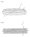
- FIG. 1 is a perspective view showing the solid electrolyte structure according to one embodiment of the present invention
- FIG. 2 is a schematic view illustrative of the configuration of the solid electrolyte structure according to one embodiment of the present invention, and showing the cross section of the solid electrolyte structure shown in FIG. 1 along the line A-A'. As shown in FIGS.
- a solid electrolyte structure 1 for all-solid-state batteries includes a plate-like dense body 2 formed of a ceramic that includes a solid electrolyte, and a porous layer 3 formed of a ceramic that includes a solid electrolyte that is the same as or different from the solid electrolyte of the dense body 2, the porous layer 3 being integrally formed on at least one surface of the dense body 2 (each surface of the plate-like dense body 2 in FIGS. 1 and 2 ) by firing.
- porous layer refers to a layer formed of a porous body having a number of pores that three-dimensionally extend from the surface to the inside of the porous body.
- the pores are filled with an active material to form an electrode.
- the term “dense body” refers to a member that does not have the above-mentioned pores (i.e., pores are not positively formed).
- the term “dense body” refers to a member in which the ceramic that includes the solid electrolyte is formed densely.
- the solid electrolyte structure 1 is a laminate in which the dense body 2 that substantially serves as a solid electrolyte and the porous layer 3 that can increases the contact area with the active material due to a large specific surface area are integrated by firing.
- the contact resistance at the interface between the solid electrolyte and the electrode can be reduced by filling pores 4 in the porous layer 3 with the active material to form an electrode so that excellent charge/discharge characteristics can be implemented.
- the dense body 2 and the porous layer 3 are a laminate body having been integrated by firing, the contact state (necking) between the dense body 2 that substantially serves as a solid electrolyte and the porous layer 3 that is filled with the active material to form an electrode is improved. Therefore, the contact resistance (grain boundary resistance) between the dense body 2 and the porous layer 3 can be reduced as compared with an all-solid-state battery in which an electrode and an electrolyte layer are merely stacked and bonded under pressure.
- the interface between the active material and the electrolyte is formed three-dimensionally and randomly. Therefore, since the stress caused by expansion and contraction of the active material during the charge/discharge operation occurs three-dimensionally and randomly, the stress can be effectively dispersed and reduced.
- the dense body 2 of the solid electrolyte structure 1 is formed of a ceramic that includes a solid electrolyte.
- the dense body 2 is in the shape of a plate.
- the dense body 2 is disposed to separate the positive electrode and the negative electrode of the all-solid-state battery, and substantially serves as a solid electrolyte.
- the solid electrolyte included in the ceramic that forms the dense body 2 is not particularly limited.
- a known solid electrolyte may be used.
- a solid electrolyte that includes lithium as a mobile ion may be suitably used as the solid electrolyte included in the ceramic that forms the dense body 2.
- Examples of an electrolyte preferably used as the solid electrolyte include Li 3 PO 4 , LiPON prepared by mixing nitrogen with Li 3 PO 4 , a lithium ion conductive glassy solid electrolyte (e.g., Li 2 S-SiS 2 , Li 2 S-P 2 S 5 , and Li 2 S-B 2 S 3 ), a lithium ion conductive solid electrolyte prepared by doping such a glassy solid electrolyte with a lithium halide (e.g., LiI) or a lithium oxyacid salt (e.g., Li 3 PO 4 ), and so on.
- a lithium ion conductive glassy solid electrolyte e.g., Li 2 S-SiS 2 , Li 2 S-P 2 S 5 , and Li 2 S-B 2 S 3
- LiI lithium ion conductive solid electrolyte prepared by doping such a glassy solid electrolyte with a lithium halide (e.g., LiI
- a titanium oxide-type solid electrolyte that contains lithium, titanium, and oxygen e.g., Li x La y TiO 3 (wherein 0 ⁇ x ⁇ 1 and 0 ⁇ y ⁇ 1)
- a phosphoric acid compound e.g., Li 1+x Al x Ti 2-x (PO 4 ) 3 and Li 1+x Al x Ge 2-x (PO 4 ) 3 (wherein 0 ⁇ x ⁇ 1), and the like are preferable since these compounds exhibit stable performance during firing in an oxygen atmosphere.
- Solid electrolyte examples include Li 0.35 La 0.55 TiO 3 and the like.
- the solid electrolyte is still more preferably Li 1.5 Al 0.5 Ge 1.5 (PO 4 ) 3 that is a NASICON-type phosphoric acid compound.
- the thickness of the dense body 2 is not particularly limited, but is preferably 5 ⁇ m to 1 mm, and more preferably 5 to 100 ⁇ m.
- the porous layer 3 of the solid electrolyte structure 1 is formed of a ceramic that includes a solid electrolyte that is the same as or different from the solid electrolyte of the dense body 2, and is integrally formed on at least one surface of the dense body 2 by firing.
- the porous layer 3 has a number of pores 4 that three-dimensionally extend from the surface to the inside of the porous layer 3.
- the pores 4 are filled with the active material to form an electrode.
- the solid electrolyte included in the ceramic that forms the porous layer 3 is not particularly limited.
- a known solid electrolyte may be used.
- any of the substances mentioned above as the solid electrolyte of the dense body 2 may be used as the solid electrolyte.
- the solid electrolyte of the porous layer 3 may be the same as or different from the solid electrolyte of the dense body 2. It is preferable to use the same solid electrolyte as that of the dense body 2 since the contact resistance between the porous layer 3 and the dense body 2 can be further reduced.
- each of the solid electrolyte included in the ceramic that forms the dense body 2 and the solid electrolyte included in the ceramic that forms the porous layer 3 be a phosphoric acid compound, for example. According to this configuration, the internal resistance of an all-solid-state battery produced using the solid electrolyte structure can be reduced.
- the thickness of the porous layer 3 is not particularly limited, but is preferably 5 ⁇ m to 1 mm, and more preferably 5 to 500 ⁇ m.
- the porosity of the porous layer 3 is preferably 10 to 70 vol%, and more preferably 30 to 60 vol%.
- porosity used herein refers to a value measured by mercury porosimetry.
- the porous layer 3 be integrally formed on at least one surface of the dense body 2 by firing.
- the porous layer 3 be formed on each surface of the dense body 2, as shown in FIGS. 1 and 2 .
- the positive electrode and the negative electrode of the all-solid-state battery can be formed in the pores 4 in the respective porous layers 3.
- the porous layer 3 is formed on only one surface of the dense body 2 (not shown) , one of the positive electrode and the negative electrode is formed in the pores in the porous layer, and the other of the positive electrode and the negative electrode is disposed on the surface of the dense body opposite to the side on which the porous layer is formed to obtain an all-solid-state battery.
- the porous layer 3 may be formed using a ceramic material that includes optimum amounts of a binder and an organic solvent in addition to the solid electrolyte corresponding to the shape of the pores 4 formed in the porous layer 3, or may be formed using a ceramic material that further includes a pore-forming agent (e.g., theobromine, starch, or carbon) that is appropriately selected corresponding to the firing atmosphere, for example.
- a pore-forming agent e.g., theobromine, starch, or carbon
- a method of producing a solid electrolyte structure according to one embodiment of the present invention is described in detail below.
- the method of producing a solid electrolyte structure according to this embodiment is used to produce the solid electrolyte structure 1 for all-solid-state batteries shown in FIGS. 1 and 2 that includes the dense body 2 formed of a ceramic that includes a solid electrolyte, and the porous layer 3 formed of a ceramic that includes a solid electrolyte that is integrally formed on at least one surface of the dense body 2 by firing.
- the method of producing a solid electrolyte structure includes: forming a first ceramic material that includes a solid electrolyte in the shape of a plate to obtain a first formed body 12, and firing the first formed body 12 to form a dense body 2 (see FIG. 3 ) (hereinafter referred to as "step (1)"); and applying a second ceramic material that includes a solid electrolyte that is the same as or different from the solid electrolyte of the dense body 2 to at least one surface of the dense body 2 (each surface of the dense body 2 in FIG. 4 ) to form a second formed body 13, and firing the second formed body 13 together with the dense body 2 at a temperature lower than the firing temperature employed for the first formed body 12 (see FIG.
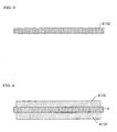
- FIG. 3 is a schematic view illustrative of the step (1) of the method of producing a solid electrolyte structure according to one embodiment of the present invention
- FIG. 4 is a schematic view illustrative of the step (2) of the method of producing a solid electrolyte structure according to one embodiment of the present invention.
- the solid electrolyte structure 1 shown in FIG. 1 can be easily and inexpensively produced.
- Each step of the method of producing a solid electrolyte structure according to this embodiment is described in detail below.
- the dense body 2 of the solid electrolyte structure 1 (see FIG. 1 ) is formed, as shown in FIG. 3 .
- the first formed body 12 may be formed by a press method, a doctor-blade method, a reverse roll coating method, or the like.
- a press method a die or the like is filled with the powdery first ceramic material that includes a solid electrolyte, and the first ceramic material is pressurized to obtain the first formed body 12.
- the shape and the thickness of the first formed body 12 may be appropriately selected corresponding to the configuration of the all-solid-state battery produced using the solid electrolyte structure.
- the thickness of the first formed body 12 is preferably 5 ⁇ m to 1 mm, and more preferably 5 to 100 ⁇ m.
- the first formed body 12 thus obtained is fired in a given atmosphere under firing conditions set corresponding to the type of solid electrolyte to form the dense body 2.
- the porous layer 3 is integrally formed by firing on at least one surface of the plate-like dense body 2 obtained by the step (1), as shown in FIG. 4 .
- the second ceramic material that is fired to form the porous layer 3 is applied to at least one surface of the dense body 2 to obtain the second formed body 13.
- the second ceramic material may be applied using a screen printing method or the like.
- the second ceramic material may be a ceramic material that includes optimum amounts of a binder and an organic solvent in addition to the solid electrolyte corresponding to the shape of the pores formed in the porous layer 3, or may be a ceramic material that further includes a pore-forming agent (e.g., theobromine, starch, or carbon) that is appropriately selected corresponding to the firing atmosphere, for example.
- a pore-forming agent e.g., theobromine, starch, or carbon
- the pore-forming agent a material that is decomposed at a temperature lower than the firing temperature employed when forming the porous layer 3 is selected. The pore-forming agent disappears due to firing so that pores are formed.
- the second formed body 13 be formed on at least one surface of the dense body 2. However, it is preferable to form the second formed body 13 on each surface of the dense body 2 so that the positive electrode and the negative electrode of the all-solid-state battery can be formed in the pores in the respective porous layers 3.
- the shape and the thickness of the second formed body 13 may be appropriately selected corresponding to the configuration of the all-solid-state battery produced using the solid electrolyte structure.
- the thickness of the second formed body 13 is preferably 5 ⁇ m to 1 mm, and more preferably 5 to 500 ⁇ m.
- the second formed body 13 is then fired together with the dense body 2 at a temperature lower than the firing temperature employed for the first formed body 12 (see FIG. 3 ) to form the porous layer 3 that is integrally formed on at least one surface of the dense body 2.
- the firing operation can be completed before the pores formed by decomposition of the binder, the pore-forming agent, and the like are lost due to shrinkage, by firing the second formed body 13 at a temperature lower than the firing temperature employed for the first formed body 12 (see FIG. 3 ) . Therefore, the porous layer 3 that has a number of pores that three-dimensionally extend from the surface to the inside of the porous layer 3 can be formed advantageously.
- the firing temperature may be appropriately determined corresponding to the types of solid electrolyte, binder, pore-forming agent, and so on.
- An excellent contact area (necking) between the particles of the porous layer 3 can be formed by firing the second formed body 13 at a temperature lower than the firing temperature employed for the first formed body 12 (see FIG. 3 ). Moreover, an excellent contact area (necking) can also be formed at the interface between the dense body 2 and the porous layer 3. If the firing temperature is too low, necking between the particles may become insufficient so that the contact resistance (grain boundary resistance) at the interface between the dense body 2 and the porous layer 3 may increase. It is preferable that the firing temperature employed for the second formed body 13 be lower than the firing temperature employed for the first formed body 12 (see FIG. 3 ) by 10 to 200°C, and more preferably 30 to 100°C, for example.
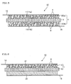
- FIG. 5 is a schematic view illustrative of the configuration of the all-solid-state battery according to one embodiment of the present invention.
- an all-solid-state battery 10 according to this embodiment includes the solid electrolyte structure 1 (see FIG. 1 ) according to one embodiment of the present invention, and an electrode 11 formed of an active material provided in the pores 4 in the porous layer 3 of the solid electrolyte structure 1.
- the porous layer 3 (3a and 3b) is formed on each surface of the dense body 2 of the solid electrolyte structure 1.
- a positive electrode 11a is formed of an active material in the pores 4 in one porous layer 3a
- a negative electrode 11b is formed of an active material in the pores 4 in the other porous layer 3b.
- a positive collector 14 is electrically connected to the positive electrode 11a.
- a negative collector 15 is electrically connected to the negative electrode 11b.
- the dense body 2 of the solid electrolyte structure 1 substantially serves as a solid electrolyte of the all-solid-state battery 10, and the positive electrode 11a and the negative electrode 11b formed of the active material in the pores 4 in the porous layer 3 having a large specific surface area are disposed on either side of the dense body 2. Therefore, excellent charge/discharge characteristics can be implemented by reducing the contact resistance at the interface between the solid electrolyte and the electrode.
- the dense body 2 and the porous layer 3 that form the solid electrolyte structure 1 are integrated by firing, the contact state (necking) between the dense body 2 that substantially serves as a solid electrolyte and the porous layer 3 that is filled with the active material to form an electrode is improved. Therefore, the contact resistance between the dense body 2 and the porous layer 3 can be reduced as compared with an all-solid-state battery in which an electrode and an electrolyte layer are merely stacked and bonded under pressure.
- the porous layer 3 (3a and 3b) is formed on each surface of the dense body 2 of the solid electrolyte structure 1.
- the porous layer 3 may be formed only on one surface of the dense body 2 of the solid electrolyte structure 1, as shown in FIG. 6 .
- an electrode 21 e.g., positive electrode
- an electrode 22 e.g., negative electrode
- a solid electrolyte structure configured in the same manner as the above-described solid electrolyte structure 1 (see FIG. 1 ) according to one embodiment of the present invention may be suitably used for the all-solid-state battery 10 according to this embodiment.
- the types of solid electrolyte included in the ceramics that form the dense body 2 and the porous layer 3 of the solid electrolyte structure 1 may be appropriately selected corresponding to the type of the active material that forms the positive electrode 11a and the negative electrode 11b.
- the solid electrolyte that forms the solid electrolyte structure 1 have a sintering temperature higher than that of the active material that forms the electrode 11. According to this configuration, the reactivity of the active materials with the solid electrolyte structure suppressed during firing.
- At least one of the positive electrode 11a and the negative electrode 11b (the positive electrode 11a and the negative electrode 11b in FIG. 5 ) of the all-solid-state battery 10 according to this embodiment is formed of the active material in the pores 4 in the porous layer 3 of the solid electrolyte structure 1.
- the electrode 11 may be formed by filling the pores 4 in the porous layer 3 with an active material precursor.
- the electrode 21 is formed of the active material provided in the pores 4 in the porous layer 3
- the electrode 22 is formed by an electrode material that includes the active material in the shape of a thin film or a sheet having a given thickness.
- the electrode 22 may be produced by a press method, a doctor-blade method, a roll coating method, or the like, and may be disposed on the side of the dense body 2 opposite to the surface on which the porous layer 3 is formed, by a sputtering method, a resistive heating deposition method that heats and deposits the deposition source using a resistor, an ion-beam deposition method that heats and deposits the deposition source using ion beams, an electron beam deposition method that heats and deposits the deposition source using electron beams, or the like.
- the positive electrode 11a shown in FIG. 5 is formed of a positive electrode active material (positive active material).
- the positive active material is not particularly limited.
- a positive active material generally used for all-solid-state batteries may be used.
- the secondary battery can be sintered in an oxygen atmosphere.
- the positive active material include manganese dioxide (MnO 2 ), iron oxide, copper oxide, nickel oxide, a lithium-manganese composite oxide (e.g., Li x Mn 2 O 4 and Li x MnO 2 ), a lithium-nickel complex oxide (e.g., Li x NiO 2 ), a lithium-cobalt complex oxide (e.g., Li x CoO 2 ), a lithium-nickel-cobalt complex oxide (e.g., LiNi 1-y Co y O 2 ), a lithium-manganese-cobalt complex oxide (e.g., LiMn y Co 1-y O 2 ), a spinel-type lithium-manganese-nickel complex oxide (e.g., Li x Mn 2-y Ni y O 4 ), a lithium phosphate compound having an olivine structure (e.g., Li x FePO 4 , Li x Fe 1-y Mn y PO 4 , and Li x Co
- the positive electrode may appropriately include an electron conduction assistant in addition to the positive active material.
- the electron conduction assistant include acetylene black, carbon black, graphite, carbon fibers, carbon nanotubes, and the like.
- the electron conductivity in the layer that forms the electrode can be improved by adding the electron conduction assistant so that the internal resistance of the battery due to electron conduction can be reduced.
- the electron conduction assistant is used to assist the electron conductivity of the active material used as the electrode.
- the electron conduction assistant may not be added when the active material exhibits electron conductivity.
- the electron conductivity is improved by adding the electron conduction assistant so that the battery characteristics can be improved.
- a more preferable positive active material examples include LiCoO 2 , Li x Mn 2 O 4 , Li x MnO 2 , and the like.
- the positive active material is still more preferably Li 3 V 2 (PO 4 ) 3 that is a lithium phosphate compound having a NASICON structure.
- the negative electrode 11b is formed of a negative electrode active material (negative active material).
- the negative active material is not particularly limited.
- a negative active material generally used for all-solid-state batteries may be used.
- the negative active material include carbon, lithium metal (Li), a metal compound, a metal oxide, a Li metal compound, a Li metal oxide (including a lithium-transition metal complex oxide), boron-doped carbon, graphite, a compound having a NASICON structure, and the like. These materials may be used either individually or in combination. For example, the capacity of the all-solid-state battery can be increased when using lithium metal (Li).
- Examples of carbon include a carbon material such as graphitic carbon, hard carbon, and soft carbon.
- Examples of the metal compound include LiAl, LiZn, Li 3 Bi, Li 3 Cd, Li 3 Sd, Li 4 Si, Li 4.4 Pb, Li 4.4 Sn, Li 0.17 C(LiC 6 ), and the like.
- Examples of the metal oxide include SnO, SnO 2 , GeO, GeO 2 , In 2 O, In 2 O 3 , PbO, PbO 2 , Pb 2 O 3 , Pb 3 O 4 , Ag 2 O, AgO, Ag 2 O 3 , Sb 2 O 3 , Sb 2 O 4 , Sb 2 O 5 , SiO, ZnO, CoO, NiO, TiO 2 , FeO, and the like.
- Examples of the Li metal compound include Li 3 FeN 2 , Li 2.6 Co 0.4 N, Li 2.6 Cu 0.4 N, and the like.
- Examples of the Li metal oxide (lithium-transition metal complex oxide) include a lithium-titanium complex oxide shown by Li 4 Ti 5 O 12 and the like.
- Examples of boron-doped carbon include boron-doped carbon, boron-doped graphite, and the like.
- the negative electrode may appropriately include a conduction assistant in addition to the negative active material.
- a material similar to the conduction assistant mentioned for the positive active material may be suitably used.
- the compound having a NASICON structure include a lithium phosphate compound (e.g., Li x V 2 (PO 4 ) 3 ) and the like.
- a more preferable negative active material include Li 4 Ti 5 O 12 , TiO 2 , and the like.
- the negative active material is still more preferably Li 3 V 2 (PO 4 ) 3 that is a lithium phosphate compound having a NASICON structure.
- the solid electrolyte included in the ceramic material that forms the solid electrolyte structure be a phosphoric acid compound
- the active material positive active material and negative active material
- the electrode 11 formed in the pores 4 in the porous layer 3 may be formed using an active material precursor in which the refined active material is dispersed in the form of a colloid using an organic solvent, an aqueous solvent, pure water, or the like, or an active material precursor that is a sol of the active material, for example.
- the pores in the porous layer be filled with the active material in a state in which the pores have an opening therein (i.e., the pores in the porous layer are not completely filled with the active material).
- the active material repeatedly undergoes expansion and contraction when ions enter and exit the porous layer during the charge/discharge operation of the battery.
- Examples of the material that forms the positive collector 14 and the negative collector 15 used for the all-solid-state battery 10 according to this embodiment include electron-conductive metal materials such as platinum (Pt), platinum (Pt)/palladium (Pd), gold (Au), silver (Ag), aluminum (Al), copper (Cu), indium-tin oxide (ITO), and an SUS plate.
- electron-conductive metal materials such as platinum (Pt), platinum (Pt)/palladium (Pd), gold (Au), silver (Ag), aluminum (Al), copper (Cu), indium-tin oxide (ITO), and an SUS plate.
- the method of producing an all-solid-state battery according to this embodiment includes producing a solid electrolyte structure by the method of producing a solid electrolyte structure according to one embodiment of the present invention, filling pores in a porous layer that forms the solid electrolyte structure with an active material precursor, and firing the active material precursor to form an electrode.
- the first ceramic material that includes a solid electrolyte is formed in the shape of a plate to obtain the first formed body 12, and the first formed body 12 is fired to form the dense body 2 (see FIG. 3 ).
- the second ceramic material that includes a solid electrolyte that is the same as or different from the solid electrolyte of the dense body 2 is applied to at least one surface of the dense body 2 (each surface of the dense body 2 in FIG. 4 ) to form the second formed body 13.
- the second formed body 13 is fired together with the dense body 2 at a temperature lower than the firing temperature employed for the first formed body 12 (see FIG. 3 ) to form the porous layer 3 that is integrally formed on at least one surface of the dense body 2 (see FIG. 4 ).
- the pores 4 (see FIG. 2 ) in the porous layer 3 of the solid electrolyte structure 1 are filled with an active material precursor, and the active material precursor provided in the pores 4 is fired to form the electrode 11 shown in FIG. 5 .
- the steps carried out to obtain the solid electrolyte structure 1 are the same as those of the method of producing a solid electrolyte structure according to one embodiment of the present invention. Therefore, description thereof is omitted.
- an active material precursor in which the refined active material such as the positive active material or the negative active material described for the all-solid-state battery according to the present invention is dispersed in the form of a colloid using an organic solvent, an aqueous solvent, pure water, or the like, or an active material precursor that is a sol of the active material may be used, for example.
- the pores 4 in the porous layer 3 of the solid electrolyte structure 1 may be filled with the active material precursor by dripping the active material precursor sol onto the surface of the porous layer 3 in air, an Ar atmosphere or under vacuum, or dipping the solid electrolyte structure 1 in the active material precursor sol, and causing the pores 4 in the porous layer 3 to be impregnated with the active material precursor under vacuum, for example.
- the active material precursor with which the pores 4 in the porous layer 3 are filled is fired (heated) together with the solid electrolyte structure to volatilize the liquid (e.g., organic solvent) contained in the active material precursor (or burn the organic substance).
- the filling operation is repeated so that the pores 4 in the porous layer 3 are sufficiently filled with the active material precursor.
- the porous layer 3 is formed on each surface of the dense body 2 of the solid electrolyte structure 1 (see FIG. 5 ), the pores 4 in the porous layers 3 are filled with the positive active material precursor or the negative active material precursor, and the active material precursors are then fired.
- the electrode 21 is formed by filling the pores 4 in the porous layer 3 with the active material precursor using the above-mentioned method.
- the electrode 22 is formed by a press method, a doctor-blade method, a roll coating method, or the like, and is disposed on the surface of the dense body 2 opposite to the surface on which the porous layer 3 is formed, by a method that applies and bonds the active material precursor or an adhesive paste formed of the same raw material as the solid electrolyte, a sputtering method, a resistive heating deposition method that heats and deposits the deposition source using a resistor, an ion-beam deposition method that heats and deposits the deposition source using ion beams, an electron beam deposition method that heats and deposits the deposition source using electron beams, or the like.
- the electrode 22 may be formed by lithium metal (Li). In this case, the charge/discharge capacity increases.
- the method of producing an all-solid-state battery according to this embodiment may further include disposing the positive collector 14 and the negative collector 15 on the electrodes 11 (positive electrode 11a and negative electrode 11b).
- the material for the positive collector 14 and the negative collector 15 include platinum (Pt), platinum (Pt)/palladium (Pd), gold (Au), silver (Ag), aluminum (Al), copper (Cu), an indium-tin oxide film (ITO), an electron-conductive metal material, and the like.
- the positive collector 14 and the negative collector 15 may be disposed on the electrodes 11 (positive electrode 11a and negative electrode 11b) by a sputtering method, a resistive heating deposition method that heats and deposits the deposition source using a resistor, an ion-beam deposition method that heats and deposits the deposition source using ion beams, an electron beam deposition method that heats and deposits the deposition source using electron beams, or the like.
- a sputtering method a resistive heating deposition method that heats and deposits the deposition source using a resistor
- an ion-beam deposition method that heats and deposits the deposition source using ion beams
- an electron beam deposition method that heats and deposits the deposition source using electron beams, or the like.
- An Li 0.35 La 0.55 TiO 3 (solid electrolyte) powder (first ceramic material) was formed with a press-mold to obtain a first formed body having a diameter of about 13 mm and a thickness of 1 mm (dimensions after firing). The first formed body was fired at 1150°C in air to obtain a dense body.
- a screen printing paste (second ceramic material) was prepared using a solid electrolyte powder having the same composition as that of the solid electrolyte used for the first formed body.
- S-LEC B manufactured by Sekisui Chemical Co., Ltd.
- bin bin
- CS-12 manufactured by Chisso Corporation
- organic solvent organic solvent
- theobromine pore-forming agent
- the second formed body was fired together with the dense body at a temperature lower than the firing temperature employed for the first formed body to form a porous layer that is integrally formed on at least one surface of the dense body.
- a solid electrolyte structure was thus produced.
- the second formed body was fired at 1100°C in air.
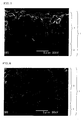
- FIG. 7 shows an SEM photograph of the cross section of the dense body 2 and the porous layer 3 of the solid electrolyte structure 1 produced in Example 1.
- the pores in the porous layer of the solid electrolyte structure were filled with an active material precursor sol to form an electrode.
- an active material precursor sol As the positive active material precursor, an LiCoO (LiCoO 2 precursor) sol solution was used.
- As the negative active material precursor an LiTiO (Li 4 Ti 5 O 12 precursor) sol solution was used.
- the pores were filled with the active material precursor by dripping the active material precursor onto the porous layer and causing the pores to be impregnated with the active material precursor under vacuum.
- the step of filling the pores with the active material precursor was repeated until the pores were filled with a desired amount of active material precursor.
- the product was fired at 450°C in air to burn the remaining organic component each time of the filling operation was performed.
- the active material precursor was fired to form an electrode.
- the active material precursor was fired after filling the pores with the negative active material precursor and after filling the pores with the positive active material precursor. Specifically, after filling the pores with the negative active material precursor (Li 4 Ti 5 O 12 ), the active material precursor was fired at 800°C to form the negative electrode. Then, after filling the pores with the positive active material precursor (LiCoO 2 ), the active material precursor was fired at 700°C to form the positive electrode.
- Gold (Au) was then sputtered onto the surface of each of the positive electrode and the negative electrode to form a collector having a thickness of about 50 nm.
- An all-solid-state battery (Example 2) was produced in the same manner as in Example 1, except that the screen printing paste (second ceramic material) used to form the porous layer of the solid electrolyte structure was prepared using the solid electrolyte powder, S-LEC B (manufactured by Sekisui Chemical Co., Ltd.) (binder), and CS-12 (manufactured by Chisso Corporation) (organic solvent) so that the porous layer had a porosity lower than that of the porous layer of Example 1 and the pore size of the pores was smaller than that of the porous layer of Example 1.
- FIG. 8 shows an SEM photograph of the cross section of the dense body 2 and the porous layer 3 of the solid electrolyte structure 1 produced in Example 2.
- An Li 1.5 Al 0.5 Ge 1.5 (PO 4 ) 3 (solid electrolyte) powder (first ceramic material) was formed with a press-mold to obtain a first formed body having a diameter of about 13 mm and a thickness of 1 mm (dimensions after firing). The first formed body was fired at 840°C in air to obtain a dense body.
- the second formed body was fired together with the dense body at a temperature lower than the firing temperature employed for the first formed body to form a porous layer that is integrally formed on at least one surface of the dense body. A solid electrolyte structure was thus produced.
- the second formed body was fired at 800°C in air.
- the pores in the porous layer of the solid electrolyte structure were filled with an active material precursor sol to form an electrode.
- an active material precursor sol As the positive active material precursor, an LiFePO 4 precursor sol solution was used.
- an Li 3 V 2 (PO 4 ) 3 precursor sol solution As the negative active material precursor, an Li 3 V 2 (PO 4 ) 3 precursor sol solution was used.
- the pores were filled with the active material precursor by dripping the active material precursor onto the porous layer and causing the pores to be impregnated with the active material precursor under vacuum.
- the active material precursor was fired to form an electrode.
- the active material precursor was fired after filling the pores with the positive active material precursor and after filling the pores with the negative active material precursor.
- the active material precursor was fired at 600°C in an Ar atmosphere when forming the negative electrode and the positive electrode.
- Gold (Au) was then sputtered onto the surface of each of the positive electrode and the negative electrode to form a collector having a thickness of about 50 nm.
- the solid electrolyte structure in which the electrode was formed in the pores in the porous layer and the collector was formed on the surface of the porous layer was dried by heating under vacuum (130°C, overnight), and incorporated in a CR2032 coin battery in a glove box containing an inert gas to obtain an all-solid-state battery (Example 3).
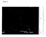
- FIG. 9 shows an SEM photograph of the cross section of the dense body 2 and the porous layer 3 of the solid electrolyte structure 1 produced in Example 4.
- the pores in the porous layer of the solid electrolyte structure were filled with an active material precursor sol to form an electrode.
- an active material precursor sol As the positive active material precursor, an Li 3 V 2 (PO 4 ) 3 precursor sol solution was used.
- As the negative active material precursor an Li 3 V 2 (PO 4 ) 3 precursor sol solution was also used.
- the pores were filled with the active material precursor by dripping the active material precursor onto the porous layer and causing the pores to be impregnated with the active material precursor under vacuum in the same manner as in Example 3.
- the step of filling the pores with the active material precursor was repeated until the pores were filled with a desired amount of active material precursor.
- the product was dried at 80°C in air each time of the filling operation was performed.
- the active material precursor was fired to form an electrode.
- the active material precursor was fired once after filling the pores with the negative active material and the positive active material.
- the active material precursor was fired at 600°C under an Ar atmosphere.
- Gold (Au) was then sputtered onto the surface of each of the positive electrode and the negative electrode to form a collector having a thickness of about 50 nm.
- the solid electrolyte structure in which the electrode was formed in the pores in the porous layer and the collector was formed on the surface of the porous layer was dried by heating under vacuum (130°C, overnight), and incorporated in a CR2032 coin battery in a glove box filling with an inert gas to obtain an all-solid-state battery (Example 4).
- a solid electrolyte powder having the same composition as that of the solid electrolyte used for the first formed body and an electrode material powder formed of the same active material as the active material for the positive electrode or the negative electrode of Example 1 were mixed to obtain a mixed powder.
- S-LEC B manufactured by Sekisui Chemical Co., Ltd.
- bin bin
- CS-12 manufactured by Chisso Corporation
- the negative electrode screen printing paste containing the negative active material was applied to one surface of the dense body by a screen printing method, and then fired at 800°C.
- the positive electrode screen printing paste containing the positive active material was applied to the other surface of the dense body by a screen printing method, and then fired at 700°C.
- a positive electrode and a negative electrode having a diameter of about 12 mm and a thickness of 10 ⁇ m (dimensions after firing) were thus formed on either surface of the dense body.
- Gold (Au) was then sputtered onto the surface of each of the positive electrode and the negative electrode to form a collector having a thickness of about 50 nm.
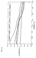
- FIG. 10 is a graph showing the measurement results.
- the vertical axis indicates AC impedance ( ⁇ ), and the horizontal axis indicates frequency (Hz).
- the graph shown in FIG. 10 is a graph showing the measurement results.
- a triangle ( ⁇ ) indicates the measurement results of Example 1
- a square ( ⁇ ) indicates the measurement results of Example 2
- a cross ( ⁇ ) indicates the measurement results of Example 3
- a diamond ( ⁇ ) indicates the measurement results of Example 4
- a circle ( ⁇ ) indicates the measurement results of Comparative Example 1.
- Example 1 Example 2
- Example 3 Example 4 Comparative Example 1 Internal impedance during charging/dischargin g (k ⁇ cm 2 ) 146 34 20 2 1747 Charge/discharge capability Possible Possible Possible Possible Impossible
- the all-solid-state batteries of Examples 1 and 2 showed good results as compared with the all-solid-state battery of Comparative Example 1 (i.e., the AC impedance decreased by about one or two digits with respect to the low-frequency-side impedance that indicates the total impedance including the reaction resistance of the electrode and the electrolyte). Good results were also obtained by the all-solid-state batteries of Examples 3 and 4 in which the phosphoric acid compound was used as the solid electrolyte and the active material.
- Example 4 in which the lithium phosphate compound having a NASICON structure was used as the active material, the internal impedance further decreased by one digit as compared with Examples 1 and 2 and Example 3 in which the lithium phosphate compound having an olivine structure was used.
- the all-solid-state battery according to the present invention showed better results by selecting appropriate materials for the solid electrolyte and the active material.
- the all-solid-state battery of Comparative Example 1 had a very high internal impedance during charging/discharging so that charging and discharging were impossible.
- the all-solid-state batteries of Examples 1 to 4 had a low internal impedance during charging/discharging so that charging and discharging were possible.
- the all-solid-state battery according to the present invention is suitable as a battery for portable instruments, a built-in battery for IC cards, a battery for medical implant equipment, a battery mounted on a substrate surface, a battery (hybrid power supply battery) used in combination with another battery (e.g., solar battery), and the like.
Landscapes
- Chemical & Material Sciences (AREA)
- Engineering & Computer Science (AREA)
- Ceramic Engineering (AREA)
- Materials Engineering (AREA)
- Manufacturing & Machinery (AREA)
- Structural Engineering (AREA)
- Chemical Kinetics & Catalysis (AREA)
- Electrochemistry (AREA)
- General Chemical & Material Sciences (AREA)
- Organic Chemistry (AREA)
- Inorganic Chemistry (AREA)
- General Physics & Mathematics (AREA)
- Condensed Matter Physics & Semiconductors (AREA)
- Physics & Mathematics (AREA)
- Secondary Cells (AREA)
- Battery Electrode And Active Subsutance (AREA)
- Compositions Of Oxide Ceramics (AREA)
Abstract
Description
- The present invention relates to a solid electrolyte structure for all-solid-state batteries, an all-solid-state battery, and methods of producing the same. More particularly, the present invention relates to a solid electrolyte structure for all-solid-state batteries that can reduce the contact resistance at the interface between the solid electrolyte and an electrode, an all-solid-state battery using the solid electrolyte structure, and methods of producing the same.
- In recent years, along with the remarkable development of portable instruments such as personal computers and portable telephones, batteries used to supply power to such portable instruments have been in great demand. In a battery used in such applications, a liquid electrolyte (electrolytic solution) utilizing a flammable organic solvent (dilution solvent) has been used as a medium through which ions move. A battery that utilizes such an electrolytic solution may ignite or explode due to leakage of the electrolytic solution, for example.
- In order to solve such a problem, an all-solid-state battery that utilizes a solid electrolyte instead of a liquid electrolyte and is entirely formed of solid elements has been developed in order to ensure safety. Since the electrolyte of the all-solid-state battery is formed of a sintered ceramic (solid), leakage or ignition does not occur. Moreover, a deterioration in battery performance due to corrosion rarely occurs, for example. In particular, an all-solid-state lithium secondary battery has been extensively studied as a secondary battery of which the energy density can be easily increased (see
Patent Document 1, for example). - The all-solid-state battery exhibits excellent safety and the like. On the other hand, since the entire electrolyte is solid, an improvement of ion conductivity of the solid electrolyte, a reduction of contact resistance (grain boundary resistance) between the electrolyte particles, and a reduction of contact resistance at the interface between the electrode and the electrolyte have been desired.
- For example, since a liquid lithium ion secondary battery utilizes a liquid electrolyte, the space between the particles of the solid electrode and electrolyte is filled with the liquid electrolyte easily. Therefore, the contact area between the solid electrode and the liquid electrolyte does not correspond to the surface area of the solid electrode, but corresponds to the specific surface area of the solid electrode. The solid electrode advantageously comes in contact with the electrolyte when the solid electrode is sufficiently filled with the electrolyte.
- Since the electrode and the electrolyte of the all-solid-state battery are solid, the contact area between the solid electrode and the electrolyte depends on the contact area between the particles of the solid electrode and the particles of the electrolyte. When the electrode and the electrolyte are not sufficiently sintered due to a low firing temperature, the particles of the solid electrode come in point-contact with the particles of the electrolyte. When the electrode and the electrolyte are sufficiently sintered so that the particles are fusion-bonded, the contact area between the particles increases so that the contact resistance (grain boundary resistance) at the interface decreases. Specifically, the contact resistance decreases as the contact area (necking) between the particles increases. However, since the reactivity of the materials must be taken into consideration when employing a firing temperature at which sufficient necking occurs, a substantial contact area cannot be easily obtained.
- When producing an all-solid-state battery by way of trial, an electrode material (e.g., active material precursor) is applied to the flat surface of a solid electrolyte and is fired to form an electrode. In this case, the contact area does not exceed the area of the surface on which the electrode is formed. Since the contact area is the total area in which the particles of the electrode come in contact with the particles of the solid electrolyte, the contact area is generally smaller than the total surface area of the electrode.
- In order to reduce the contact resistance (grain boundary resistance) at the interface between the electrode and the solid electrolyte, an all-solid-state battery in which a solid electrolyte is interposed between particles of an active material used for positive and negative electrodes has been disclosed (see
Patent Document 2, for example). Specifically, the positive electrode and the negative electrode are formed by firing a green sheet obtained by forming a slurry prepared by mixing an active material and an electrolyte in the shape of a sheet, and the solid electrolyte (solid electrolyte layer) disposed between the electrodes is formed by firing a sheet formed only of a solid electrolyte material. The positive electrode, the solid electrolyte layer, and the negative electrode thus produced are press-bonded or fired under pressure to produce an all-solid-state battery. Such an all-solid-state battery is considered to allow an electrolyte network to be formed in the active material of the positive and negative electrodes. -
- Patent Document 1:
JP-A-5-205741 - Patent Document 2:
JP-A-2000-311710 - According to the method of producing the all-solid-state battery disclosed in
Patent Document 2, if the active material and the solid electrolyte differ in sintering temperature, the contact resistance (grain boundary resistance) at the interface cannot be reduced so that excellent charge/discharge characteristics cannot be obtained. Specifically, the electrodes of the all-solid-state battery disclosed inPatent Document 2 are formed using a material prepared by mixing the positive/negative active material and the solid electrolyte. However, since the active material and the solid electrolyte differ in sintering temperature, a sufficient contact area (necking) cannot be formed when the material has a high sintering temperature. - On the other hand, when the active material and the solid electrolyte have a similar sintering temperature, the materials react with each other so that another substance is produced between the materials. As a result, the performance of the active material deteriorates so that the charge/discharge capacity may decrease or the reaction resistance may increase. Therefore, a material design that can overcome such problems is desired in order to maintain the performance of the active material while reducing the contact resistance.
- In the charge/discharge process of the secondary battery, the active material repeatedly undergoes expansion and contraction when ions enter and leave the active material that forms the electrode. For example, since a liquid electrolyte having fluidity is used for a liquid secondary battery, the stress due to expansion and contraction is reduced so that the interface between the electrode and the electrolyte is not affected. On the other hand, since the stress due to expansion and contraction directly acts on the interface between the electrode and the electrolyte of the all-solid-state battery, cracks and the like occur at the interface between the electrode and the electrolyte so that delamination occurs. As a result, the charge/discharge operation is hindered. When delamination occurs to a larger extent, the function of the battery is impaired.
- The present invention was conceived in view of the above-described problems. An object of the present invention is to provide a solid electrolyte structure for all-solid-state batteries that can reduce the contact resistance at the interface between the solid electrolyte and an electrode, and can effectively disperse and reduce the stress caused by expansion and contraction of an active material during the charge/discharge process, an all-solid-state battery using such a solid electrolyte structure, and methods of producing the same.
- The inventors of the present invention conducted extensive studies in order to achieve the above object. As a result, the inventors found that the above object can be achieved by a solid electrolyte structure obtained by integrating a dense layer and a porous layer by firing. This finding has led to the completion of the present invention.
- According to the present invention, a solid electrolyte structure for all-solid-state batteries, an all-solid-state battery, and methods of producing the same given below are provided.
- [1] A solid electrolyte structure for all-solid-state batteries, the solid electrolyte structure comprising a plate-like dense body formed of a ceramic that includes a solid electrolyte, and a porous layer formed of a ceramic that includes a solid electrolyte that is the same as or different from the solid electrolyte of the dense body, the porous layer being integrally formed on at least one surface of the dense body by firing.
- [2] The solid electrolyte structure according to [1], wherein the porous layer has a porosity of 10 to 70 vol%.
- [3] The solid electrolyte structure according to [1] or [2], wherein the porous layer is integrally formed on each surface of the dense body by firing.
- [4] The solid electrolyte structure according to any one of [1] to [3], wherein each of the solid electrolyte included in the ceramic that forms the dense body and the solid electrolyte included in the ceramic that forms the porous layer is a phosphoric acid compound.
- [5] An all-solid-state battery comprising the all-solid-state battery according to any one of [1] to [4], and an electrode formed of an active material, pores in the porous layer of the solid electrolyte structure being filled with the active material.
- [6] The all-solid-state battery according to [5], wherein the pores in the porous layer are filled with the active material in a state in which the pores have an opening therein.
- [7] The all-solid-state battery according to [5] or [6], wherein the solid electrolyte structure has been sintered by firing a ceramic material that includes the solid electrolyte, and the solid electrolyte has a sintering temperature higher than that of the active material that forms the electrode.
- [8] The all-solid-state battery according to any one of [5] to [7], wherein the solid electrolyte is a phosphoric acid compound, and the active material is also a phosphoric acid compound.
- [9] A method of producing a solid electrolyte structure for all-solid-state batteries, the method comprising: forming a first ceramic material that includes a solid electrolyte in a shape of a plate to obtain a first formed body, and firing the first formed body to form a dense body; and applying a second ceramic material that includes a solid electrolyte that is the same as or different from the solid electrolyte of the dense body to at least one surface of the dense body to form a second formed body, and firing the second formed body together with the dense body at a temperature lower than the firing temperature employed for the first formed body to form a porous layer that is integrally formed on the at least one surface of the dense body.
- [10] A method of producing an all-solid-state battery comprising producing a solid electrolyte structure using the method according to [9], filling pores in a porous layer that forms the solid electrolyte structure with an active material precursor, and firing the active material precursor to form an electrode.
- The solid electrolyte structure and the all-solid-state battery according to the present invention can show excellent charge/discharge characteristics due to a reduction of contact resistance at the interface between the solid electrolyte and the electrode. Moreover, the stress caused by expansion and contraction of the active material during the charge/discharge process can be effectively dispersed and reduced.
- The method of producing a solid electrolyte structure and the method of producing an all-solid-state battery according to the present invention can produce the solid electrolyte structure and the all-solid-state battery to produce easily and inexpensively.
-
-
FIG. 1 is a perspective view showing a solid electrolyte structure according to one embodiment of the present invention. -
FIG. 2 is a schematic view illustrative of the configuration of the solid electrolyte structure according to one embodiment of the present invention, and showing the cross section of the solid electrolyte structure shown inFIG. 1 along the line A-A'. -
FIG. 3 is a schematic view illustrative of a step (1) of a method of producing a solid electrolyte structure according to one embodiment of the present invention. -
FIG. 4 is a schematic view illustrative of a step (2) of a method of producing a solid electrolyte structure according to one embodiment of the present invention. -
FIG. 5 is a schematic view illustrative of the configuration of an all-solid-state battery according to one embodiment of the present invention. -
FIG. 6 is a schematic view illustrative of the other configuration of an all-solid-state battery according to another embodiment of the present invention. -
FIG. 7 shows an SEM photograph of the cross section of a dense body and a porous layer of a solid electrolyte structure produced in Example 1. -
FIG. 8 shows an SEM photograph of the cross section of a dense body and a porous layer of a solid electrolyte structure produced in Example 2. -
FIG. 9 shows an SEM photograph of the cross section of a dense body and a porous layer of a solid electrolyte structure produced in Example 4. -
FIG. 10 is a graph showing AC impedance measurement results, wherein the vertical axis indicates AC impedance (Ω) and the horizontal axis indicates frequency (Hz). - 1: solid electrolyte structure, 2: dense body, 3, 3a, 3b: porous layer, 4: pore, 10: all-solid-state battery, 11, 21, 22: electrode, 11a: positive electrode, 11b: negative electrode, 12: first formed body, 13: second formed body, 14: positive collector, 15: negative collector
- Preferred embodiments of the present invention are described below. Note that the present invention is not limited to the following embodiments. Various modifications and improvements may be made of the following embodiments without departing from the scope of the present invention based on the knowledge of a person skilled in the art.
- A solid electrolyte structure for all-solid-state batteries (hereinafter may be simply referred to as "solid electrolyte structure") according to one embodiment of the present invention is described in detail below.
FIG. 1 is a perspective view showing the solid electrolyte structure according to one embodiment of the present invention,FIG. 2 is a schematic view illustrative of the configuration of the solid electrolyte structure according to one embodiment of the present invention, and showing the cross section of the solid electrolyte structure shown inFIG. 1 along the line A-A'. As shown inFIGS. 1 and 2 , asolid electrolyte structure 1 for all-solid-state batteries according to this embodiment includes a plate-likedense body 2 formed of a ceramic that includes a solid electrolyte, and aporous layer 3 formed of a ceramic that includes a solid electrolyte that is the same as or different from the solid electrolyte of thedense body 2, theporous layer 3 being integrally formed on at least one surface of the dense body 2 (each surface of the plate-likedense body 2 inFIGS. 1 and 2 ) by firing. - The term "porous layer" refers to a layer formed of a porous body having a number of pores that three-dimensionally extend from the surface to the inside of the porous body. When the solid electrolyte structure according to this embodiment is used for an all-solid-state battery, the pores are filled with an active material to form an electrode. The term "dense body" refers to a member that does not have the above-mentioned pores (i.e., pores are not positively formed). Specifically, the term "dense body" refers to a member in which the ceramic that includes the solid electrolyte is formed densely.
- The
solid electrolyte structure 1 according to this embodiment is a laminate in which thedense body 2 that substantially serves as a solid electrolyte and theporous layer 3 that can increases the contact area with the active material due to a large specific surface area are integrated by firing. The contact resistance at the interface between the solid electrolyte and the electrode can be reduced by fillingpores 4 in theporous layer 3 with the active material to form an electrode so that excellent charge/discharge characteristics can be implemented. - Since the
dense body 2 and theporous layer 3 are a laminate body having been integrated by firing, the contact state (necking) between thedense body 2 that substantially serves as a solid electrolyte and theporous layer 3 that is filled with the active material to form an electrode is improved. Therefore, the contact resistance (grain boundary resistance) between thedense body 2 and theporous layer 3 can be reduced as compared with an all-solid-state battery in which an electrode and an electrolyte layer are merely stacked and bonded under pressure. - When the pores in the porous layer are filled with the active material, the interface between the active material and the electrolyte is formed three-dimensionally and randomly. Therefore, since the stress caused by expansion and contraction of the active material during the charge/discharge operation occurs three-dimensionally and randomly, the stress can be effectively dispersed and reduced.
- The
dense body 2 of thesolid electrolyte structure 1 according to this embodiment is formed of a ceramic that includes a solid electrolyte. Thedense body 2 is in the shape of a plate. Thedense body 2 is disposed to separate the positive electrode and the negative electrode of the all-solid-state battery, and substantially serves as a solid electrolyte. - The solid electrolyte included in the ceramic that forms the
dense body 2 is not particularly limited. A known solid electrolyte may be used. For example, a solid electrolyte that includes lithium as a mobile ion may be suitably used as the solid electrolyte included in the ceramic that forms thedense body 2. Examples of an electrolyte preferably used as the solid electrolyte include Li3PO4, LiPON prepared by mixing nitrogen with Li3PO4, a lithium ion conductive glassy solid electrolyte (e.g., Li2S-SiS2, Li2S-P2S5, and Li2S-B2S3), a lithium ion conductive solid electrolyte prepared by doping such a glassy solid electrolyte with a lithium halide (e.g., LiI) or a lithium oxyacid salt (e.g., Li3PO4), and so on. Especially among these, a titanium oxide-type solid electrolyte that contains lithium, titanium, and oxygen (e.g., LixLayTiO3 (wherein 0<x<1 and 0<y<1)), a phosphoric acid compound (particularly a NASICON-type phosphoric acid compound) (e.g., Li1+xAlxTi2-x (PO4) 3 and Li1+xAlxGe2-x (PO4) 3 (wherein 0<x<1), and the like are preferable since these compounds exhibit stable performance during firing in an oxygen atmosphere. - Specific examples of a more preferable solid electrolyte include Li0.35La0.55TiO3 and the like. The solid electrolyte is still more preferably Li1.5Al0.5Ge1.5(PO4)3 that is a NASICON-type phosphoric acid compound.
- The thickness of the
dense body 2 is not particularly limited, but is preferably 5 µm to 1 mm, and more preferably 5 to 100 µm. - The
porous layer 3 of thesolid electrolyte structure 1 according to this embodiment is formed of a ceramic that includes a solid electrolyte that is the same as or different from the solid electrolyte of thedense body 2, and is integrally formed on at least one surface of thedense body 2 by firing. Theporous layer 3 has a number ofpores 4 that three-dimensionally extend from the surface to the inside of theporous layer 3. When thesolid electrolyte structure 1 is used for an all-solid-state battery, thepores 4 are filled with the active material to form an electrode. - The solid electrolyte included in the ceramic that forms the
porous layer 3 is not particularly limited. A known solid electrolyte may be used. For example, any of the substances mentioned above as the solid electrolyte of thedense body 2 may be used as the solid electrolyte. The solid electrolyte of theporous layer 3 may be the same as or different from the solid electrolyte of thedense body 2. It is preferable to use the same solid electrolyte as that of thedense body 2 since the contact resistance between theporous layer 3 and thedense body 2 can be further reduced. In thesolid electrolyte structure 1 according to this embodiment, it is preferable that each of the solid electrolyte included in the ceramic that forms thedense body 2 and the solid electrolyte included in the ceramic that forms theporous layer 3 be a phosphoric acid compound, for example. According to this configuration, the internal resistance of an all-solid-state battery produced using the solid electrolyte structure can be reduced. - The thickness of the
porous layer 3 is not particularly limited, but is preferably 5 µm to 1 mm, and more preferably 5 to 500 µm. - The porosity of the
porous layer 3 is preferably 10 to 70 vol%, and more preferably 30 to 60 vol%. The term "porosity" used herein refers to a value measured by mercury porosimetry. - It suffices that the
porous layer 3 be integrally formed on at least one surface of thedense body 2 by firing. However, it is preferable that theporous layer 3 be formed on each surface of thedense body 2, as shown inFIGS. 1 and 2 . According to this configuration, the positive electrode and the negative electrode of the all-solid-state battery can be formed in thepores 4 in the respectiveporous layers 3. When theporous layer 3 is formed on only one surface of the dense body 2 (not shown) , one of the positive electrode and the negative electrode is formed in the pores in the porous layer, and the other of the positive electrode and the negative electrode is disposed on the surface of the dense body opposite to the side on which the porous layer is formed to obtain an all-solid-state battery. - The
porous layer 3 may be formed using a ceramic material that includes optimum amounts of a binder and an organic solvent in addition to the solid electrolyte corresponding to the shape of thepores 4 formed in theporous layer 3, or may be formed using a ceramic material that further includes a pore-forming agent (e.g., theobromine, starch, or carbon) that is appropriately selected corresponding to the firing atmosphere, for example. - A method of producing a solid electrolyte structure according to one embodiment of the present invention is described in detail below. The method of producing a solid electrolyte structure according to this embodiment is used to produce the
solid electrolyte structure 1 for all-solid-state batteries shown inFIGS. 1 and 2 that includes thedense body 2 formed of a ceramic that includes a solid electrolyte, and theporous layer 3 formed of a ceramic that includes a solid electrolyte that is integrally formed on at least one surface of thedense body 2 by firing. - The method of producing a solid electrolyte structure according to this embodiment includes: forming a first ceramic material that includes a solid electrolyte in the shape of a plate to obtain a first formed
body 12, and firing the first formedbody 12 to form a dense body 2 (seeFIG. 3 ) (hereinafter referred to as "step (1)"); and applying a second ceramic material that includes a solid electrolyte that is the same as or different from the solid electrolyte of thedense body 2 to at least one surface of the dense body 2 (each surface of thedense body 2 inFIG. 4 ) to form a second formedbody 13, and firing the second formedbody 13 together with thedense body 2 at a temperature lower than the firing temperature employed for the first formed body 12 (seeFIG. 3 ) to form aporous layer 3 that is integrally formed on at least one surface of the dense body 2 (seeFIG. 4 ) (hereinafter referred to as "step (2)").FIG. 3 is a schematic view illustrative of the step (1) of the method of producing a solid electrolyte structure according to one embodiment of the present invention, andFIG. 4 is a schematic view illustrative of the step (2) of the method of producing a solid electrolyte structure according to one embodiment of the present invention. - According to the above configuration, the
solid electrolyte structure 1 shown inFIG. 1 can be easily and inexpensively produced. Each step of the method of producing a solid electrolyte structure according to this embodiment is described in detail below. - In the step (1), the
dense body 2 of the solid electrolyte structure 1 (seeFIG. 1 ) is formed, as shown inFIG. 3 . The first formedbody 12 may be formed by a press method, a doctor-blade method, a reverse roll coating method, or the like. When using a press method, a die or the like is filled with the powdery first ceramic material that includes a solid electrolyte, and the first ceramic material is pressurized to obtain the first formedbody 12. - When using a doctor-blade method or a reverse roll coating method, a binder such as polyvinyl alcohol is mixed with the first ceramic material that includes a solid electrolyte to obtain a mixture. An organic solvent such as toluene is added to the mixture to prepare a slurry. The slurry is formed into a thin film or a sheet having a given thickness using a doctor-blade method or a reverse roll coating method to obtain the first formed
body 12. In this case, the first formedbody 12 is preferably dried after forming. The first formedbody 12 may optionally be cut, for example. - The shape and the thickness of the first formed
body 12 may be appropriately selected corresponding to the configuration of the all-solid-state battery produced using the solid electrolyte structure. For example, the thickness of the first formedbody 12 is preferably 5 µm to 1 mm, and more preferably 5 to 100 µm. - The first formed
body 12 thus obtained is fired in a given atmosphere under firing conditions set corresponding to the type of solid electrolyte to form thedense body 2. - In the step (2), the
porous layer 3 is integrally formed by firing on at least one surface of the plate-likedense body 2 obtained by the step (1), as shown inFIG. 4 . - In the step (2), the second ceramic material that is fired to form the
porous layer 3 is applied to at least one surface of thedense body 2 to obtain the second formedbody 13. The second ceramic material may be applied using a screen printing method or the like. - The second ceramic material may include a solid electrolyte that is the same as or different from the solid electrolyte (the solid electrolyte of the dense body 2) used in the step (1). In the step (2), since the second ceramic material is applied to the
dense body 2 to form the second formedbody 13, a binder such as polyvinyl alcohol is mixed with the solid electrolyte to prepare a paste. - The second ceramic material may be a ceramic material that includes optimum amounts of a binder and an organic solvent in addition to the solid electrolyte corresponding to the shape of the pores formed in the
porous layer 3, or may be a ceramic material that further includes a pore-forming agent (e.g., theobromine, starch, or carbon) that is appropriately selected corresponding to the firing atmosphere, for example. As the pore-forming agent, a material that is decomposed at a temperature lower than the firing temperature employed when forming theporous layer 3 is selected. The pore-forming agent disappears due to firing so that pores are formed. - It suffices that the second formed
body 13 be formed on at least one surface of thedense body 2. However, it is preferable to form the second formedbody 13 on each surface of thedense body 2 so that the positive electrode and the negative electrode of the all-solid-state battery can be formed in the pores in the respectiveporous layers 3. - The shape and the thickness of the second formed
body 13 may be appropriately selected corresponding to the configuration of the all-solid-state battery produced using the solid electrolyte structure. For example, the thickness of the second formedbody 13 is preferably 5 µm to 1 mm, and more preferably 5 to 500 µm. - It is preferable to dry the second formed
body 13 obtained by applying the second ceramic material in order to volatilize the binder contained in the second ceramic material. - The second formed
body 13 is then fired together with thedense body 2 at a temperature lower than the firing temperature employed for the first formed body 12 (seeFIG. 3 ) to form theporous layer 3 that is integrally formed on at least one surface of thedense body 2. The firing operation can be completed before the pores formed by decomposition of the binder, the pore-forming agent, and the like are lost due to shrinkage, by firing the second formedbody 13 at a temperature lower than the firing temperature employed for the first formed body 12 (seeFIG. 3 ) . Therefore, theporous layer 3 that has a number of pores that three-dimensionally extend from the surface to the inside of theporous layer 3 can be formed advantageously. The firing temperature may be appropriately determined corresponding to the types of solid electrolyte, binder, pore-forming agent, and so on. - An excellent contact area (necking) between the particles of the
porous layer 3 can be formed by firing the second formedbody 13 at a temperature lower than the firing temperature employed for the first formed body 12 (seeFIG. 3 ). Moreover, an excellent contact area (necking) can also be formed at the interface between thedense body 2 and theporous layer 3. If the firing temperature is too low, necking between the particles may become insufficient so that the contact resistance (grain boundary resistance) at the interface between thedense body 2 and theporous layer 3 may increase. It is preferable that the firing temperature employed for the second formedbody 13 be lower than the firing temperature employed for the first formed body 12 (seeFIG. 3 ) by 10 to 200°C, and more preferably 30 to 100°C, for example. - The
solid electrolyte structure 1 for all-solid-state batteries shown inFIGS. 1 and 2 that includes thedense body 2 formed of a ceramic that includes a solid electrolyte and theporous layer 3 formed of a ceramic that includes a solid electrolyte that is the same as or different from the solid electrolyte of thedense body 2 and is integrally formed on at least one surface of the dense body 2 (each surface of thedense body 2 inFIG. 1 ) by firing, can be produced in this manner. - An all-solid-state battery according to one embodiment of the present invention is described in detail below.
FIG. 5 is a schematic view illustrative of the configuration of the all-solid-state battery according to one embodiment of the present invention. As shown inFIG. 5 , an all-solid-state battery 10 according to this embodiment includes the solid electrolyte structure 1 (seeFIG. 1 ) according to one embodiment of the present invention, and anelectrode 11 formed of an active material provided in thepores 4 in theporous layer 3 of thesolid electrolyte structure 1. - In the all-solid-
state battery 10 according to this embodiment shown inFIG. 5 , the porous layer 3 (3a and 3b) is formed on each surface of thedense body 2 of thesolid electrolyte structure 1. Apositive electrode 11a is formed of an active material in thepores 4 in oneporous layer 3a, and anegative electrode 11b is formed of an active material in thepores 4 in the other porous layer 3b. Apositive collector 14 is electrically connected to thepositive electrode 11a. Anegative collector 15 is electrically connected to thenegative electrode 11b. - In the all-solid-
state battery 10 according to this embodiment, thedense body 2 of the solid electrolyte structure 1 (seeFIG. 1 ) according to one embodiment of the present invention substantially serves as a solid electrolyte of the all-solid-state battery 10, and thepositive electrode 11a and thenegative electrode 11b formed of the active material in thepores 4 in theporous layer 3 having a large specific surface area are disposed on either side of thedense body 2. Therefore, excellent charge/discharge characteristics can be implemented by reducing the contact resistance at the interface between the solid electrolyte and the electrode. - Since the
dense body 2 and theporous layer 3 that form thesolid electrolyte structure 1 are integrated by firing, the contact state (necking) between thedense body 2 that substantially serves as a solid electrolyte and theporous layer 3 that is filled with the active material to form an electrode is improved. Therefore, the contact resistance between thedense body 2 and theporous layer 3 can be reduced as compared with an all-solid-state battery in which an electrode and an electrolyte layer are merely stacked and bonded under pressure. - In the all-solid-
state battery 10 shown inFIG. 5 , the porous layer 3 (3a and 3b) is formed on each surface of thedense body 2 of thesolid electrolyte structure 1. Note that theporous layer 3 may be formed only on one surface of thedense body 2 of thesolid electrolyte structure 1, as shown inFIG. 6 . In this case, an electrode 21 (e.g., positive electrode) may be formed of the active material in thepores 4 in theporous layer 3, and an electrode 22 (e.g., negative electrode) formed separately may be disposed on the side of thedense body 2 opposite to the surface on which theporous layer 3 is formed. Even when using thesolid electrolyte structure 1 in which theporous layer 3 is formed only on one surface of thedense body 2, excellent charge/discharge characteristics can be implemented due to a reduction in contact resistance at the interface between the solid electrolyte and the electrode. - As shown in
FIG. 5 , a solid electrolyte structure configured in the same manner as the above-described solid electrolyte structure 1 (seeFIG. 1 ) according to one embodiment of the present invention may be suitably used for the all-solid-state battery 10 according to this embodiment. The types of solid electrolyte included in the ceramics that form thedense body 2 and theporous layer 3 of thesolid electrolyte structure 1 may be appropriately selected corresponding to the type of the active material that forms thepositive electrode 11a and thenegative electrode 11b. - In the all-solid-
state battery 10 according to this embodiment, it is preferable that the solid electrolyte that forms thesolid electrolyte structure 1 have a sintering temperature higher than that of the active material that forms theelectrode 11. According to this configuration, the reactivity of the active materials with the solid electrolyte structure suppressed during firing. - As shown in
FIG. 5 , at least one of thepositive electrode 11a and thenegative electrode 11b (thepositive electrode 11a and thenegative electrode 11b inFIG. 5 ) of the all-solid-state battery 10 according to this embodiment is formed of the active material in thepores 4 in theporous layer 3 of thesolid electrolyte structure 1. Theelectrode 11 may be formed by filling thepores 4 in theporous layer 3 with an active material precursor. - When the
porous layer 3 is formed only on one surface of thedense body 2 of the solid electrolyte structure 1 (seeFIG. 6 ), theelectrode 21 is formed of the active material provided in thepores 4 in theporous layer 3, and theelectrode 22 is formed by an electrode material that includes the active material in the shape of a thin film or a sheet having a given thickness. Theelectrode 22 may be produced by a press method, a doctor-blade method, a roll coating method, or the like, and may be disposed on the side of thedense body 2 opposite to the surface on which theporous layer 3 is formed, by a sputtering method, a resistive heating deposition method that heats and deposits the deposition source using a resistor, an ion-beam deposition method that heats and deposits the deposition source using ion beams, an electron beam deposition method that heats and deposits the deposition source using electron beams, or the like. - The
positive electrode 11a shown inFIG. 5 is formed of a positive electrode active material (positive active material). The positive active material is not particularly limited. A positive active material generally used for all-solid-state batteries may be used. When using a metal oxide as the positive active material, the secondary battery can be sintered in an oxygen atmosphere. Specific examples of the positive active material include manganese dioxide (MnO2), iron oxide, copper oxide, nickel oxide, a lithium-manganese composite oxide (e.g., LixMn2O4 and LixMnO2), a lithium-nickel complex oxide (e.g., LixNiO2), a lithium-cobalt complex oxide (e.g., LixCoO2), a lithium-nickel-cobalt complex oxide (e.g., LiNi1-yCoyO2), a lithium-manganese-cobalt complex oxide (e.g., LiMnyCo1-yO2), a spinel-type lithium-manganese-nickel complex oxide (e.g., LixMn2-yNiyO4), a lithium phosphate compound having an olivine structure (e.g., LixFePO4, LixFe1-yMnyPO4, and LixCoPO4), a lithium phosphate compound having a NASICON structure (e.g., LixV2(PO4)3), iron sulfate (Fe2(SO4)3), vanadium oxide (e.g., V2O5), and the like. These materials may be used either individually or in combination. It is preferable that 1<x<5 and 0<y<1. - The positive electrode may appropriately include an electron conduction assistant in addition to the positive active material. Examples of the electron conduction assistant include acetylene black, carbon black, graphite, carbon fibers, carbon nanotubes, and the like.
- The electron conductivity in the layer that forms the electrode can be improved by adding the electron conduction assistant so that the internal resistance of the battery due to electron conduction can be reduced. The electron conduction assistant is used to assist the electron conductivity of the active material used as the electrode. The electron conduction assistant may not be added when the active material exhibits electron conductivity. When the active material does not exhibit electron conductivity, the electron conductivity is improved by adding the electron conduction assistant so that the battery characteristics can be improved.
- Specific examples of a more preferable positive active material include LiCoO2, LixMn2O4, LixMnO2, and the like. The positive active material is still more preferably Li3V2(PO4)3 that is a lithium phosphate compound having a NASICON structure.
- The
negative electrode 11b is formed of a negative electrode active material (negative active material). The negative active material is not particularly limited. A negative active material generally used for all-solid-state batteries may be used. Examples of the negative active material include carbon, lithium metal (Li), a metal compound, a metal oxide, a Li metal compound, a Li metal oxide (including a lithium-transition metal complex oxide), boron-doped carbon, graphite, a compound having a NASICON structure, and the like. These materials may be used either individually or in combination. For example, the capacity of the all-solid-state battery can be increased when using lithium metal (Li). - Examples of carbon include a carbon material such as graphitic carbon, hard carbon, and soft carbon. Examples of the metal compound include LiAl, LiZn, Li3Bi, Li3Cd, Li3Sd, Li4Si, Li4.4Pb, Li4.4Sn, Li0.17C(LiC6), and the like. Examples of the metal oxide include SnO, SnO2, GeO, GeO2, In2O, In2O3, PbO, PbO2, Pb2O3, Pb3O4, Ag2O, AgO, Ag2O3, Sb2O3, Sb2O4, Sb2O5, SiO, ZnO, CoO, NiO, TiO2, FeO, and the like. Examples of the Li metal compound include Li3FeN2, Li2.6Co0.4N, Li2.6Cu0.4N, and the like. Examples of the Li metal oxide (lithium-transition metal complex oxide) include a lithium-titanium complex oxide shown by Li4Ti5O12 and the like. Examples of boron-doped carbon include boron-doped carbon, boron-doped graphite, and the like.
- The negative electrode may appropriately include a conduction assistant in addition to the negative active material. A material similar to the conduction assistant mentioned for the positive active material may be suitably used. Examples of the compound having a NASICON structure include a lithium phosphate compound (e.g., LixV2(PO4)3) and the like.
- Specific examples of a more preferable negative active material include Li4Ti5O12, TiO2, and the like. The negative active material is still more preferably Li3V2(PO4)3 that is a lithium phosphate compound having a NASICON structure.
- In the all-solid-state battery according to this embodiment, it is preferable that the solid electrolyte included in the ceramic material that forms the solid electrolyte structure be a phosphoric acid compound, and the active material (positive active material and negative active material) be a phosphoric acid compound. This further reduces the internal resistance of the all-solid-state battery.
- The
electrode 11 formed in thepores 4 in the porous layer 3 (seeFIG. 5 ) may be formed using an active material precursor in which the refined active material is dispersed in the form of a colloid using an organic solvent, an aqueous solvent, pure water, or the like, or an active material precursor that is a sol of the active material, for example. - In the all-solid-state battery according to this embodiment, it is preferable that the pores in the porous layer be filled with the active material in a state in which the pores have an opening therein (i.e., the pores in the porous layer are not completely filled with the active material). The active material repeatedly undergoes expansion and contraction when ions enter and exit the porous layer during the charge/discharge operation of the battery. According to the above configuration, since the pores in the porous layer are not completely filled with the active material and have an opening, the stress caused by expansion and contraction of the active material is reduced so that delamination due to cracks and the like can be suppressed.
- Examples of the material that forms the
positive collector 14 and thenegative collector 15 used for the all-solid-state battery 10 according to this embodiment include electron-conductive metal materials such as platinum (Pt), platinum (Pt)/palladium (Pd), gold (Au), silver (Ag), aluminum (Al), copper (Cu), indium-tin oxide (ITO), and an SUS plate. - A method of producing an all-solid-state battery according to one embodiment of the present invention is described in detail below. The method of producing an all-solid-state battery according to this embodiment includes producing a solid electrolyte structure by the method of producing a solid electrolyte structure according to one embodiment of the present invention, filling pores in a porous layer that forms the solid electrolyte structure with an active material precursor, and firing the active material precursor to form an electrode.
- Specifically, the first ceramic material that includes a solid electrolyte is formed in the shape of a plate to obtain the first formed
body 12, and the first formedbody 12 is fired to form the dense body 2 (seeFIG. 3 ). The second ceramic material that includes a solid electrolyte that is the same as or different from the solid electrolyte of thedense body 2 is applied to at least one surface of the dense body 2 (each surface of thedense body 2 inFIG. 4 ) to form the second formedbody 13. The second formedbody 13 is fired together with thedense body 2 at a temperature lower than the firing temperature employed for the first formed body 12 (seeFIG. 3 ) to form theporous layer 3 that is integrally formed on at least one surface of the dense body 2 (seeFIG. 4 ). The pores 4 (seeFIG. 2 ) in theporous layer 3 of thesolid electrolyte structure 1 are filled with an active material precursor, and the active material precursor provided in thepores 4 is fired to form theelectrode 11 shown inFIG. 5 . - The steps carried out to obtain the
solid electrolyte structure 1 are the same as those of the method of producing a solid electrolyte structure according to one embodiment of the present invention. Therefore, description thereof is omitted. - As the active material precursor with which the
pores 4 in theporous layer 3 of thesolid electrolyte structure 1 are filled, an active material precursor in which the refined active material such as the positive active material or the negative active material described for the all-solid-state battery according to the present invention is dispersed in the form of a colloid using an organic solvent, an aqueous solvent, pure water, or the like, or an active material precursor that is a sol of the active material may be used, for example. - The
pores 4 in theporous layer 3 of thesolid electrolyte structure 1 may be filled with the active material precursor by dripping the active material precursor sol onto the surface of theporous layer 3 in air, an Ar atmosphere or under vacuum, or dipping thesolid electrolyte structure 1 in the active material precursor sol, and causing thepores 4 in theporous layer 3 to be impregnated with the active material precursor under vacuum, for example. - The active material precursor with which the
pores 4 in theporous layer 3 are filled is fired (heated) together with the solid electrolyte structure to volatilize the liquid (e.g., organic solvent) contained in the active material precursor (or burn the organic substance). When thepores 4 in theporous layer 3 are not sufficiently filled with the active material precursor by a single operation, the filling operation is repeated so that thepores 4 in theporous layer 3 are sufficiently filled with the active material precursor. - When the
porous layer 3 is formed on each surface of thedense body 2 of the solid electrolyte structure 1 (seeFIG. 5 ), thepores 4 in theporous layers 3 are filled with the positive active material precursor or the negative active material precursor, and the active material precursors are then fired. When theporous layer 3 is formed on one surface of thedense body 2 of the solid electrolyte structure 1 (seeFIG. 6 ), theelectrode 21 is formed by filling thepores 4 in theporous layer 3 with the active material precursor using the above-mentioned method. Theelectrode 22 is formed by a press method, a doctor-blade method, a roll coating method, or the like, and is disposed on the surface of thedense body 2 opposite to the surface on which theporous layer 3 is formed, by a method that applies and bonds the active material precursor or an adhesive paste formed of the same raw material as the solid electrolyte, a sputtering method, a resistive heating deposition method that heats and deposits the deposition source using a resistor, an ion-beam deposition method that heats and deposits the deposition source using ion beams, an electron beam deposition method that heats and deposits the deposition source using electron beams, or the like. For example, theelectrode 22 may be formed by lithium metal (Li). In this case, the charge/discharge capacity increases. - According to the above configuration, the all-solid-
state battery 10 that includes thesolid electrolyte structure 1 in which theporous layer 3 is integrally formed on at least one surface of thedense body 2 by firing and theelectrode 11 formed of the active material provided in thepores 4 in theporous layer 3 of thesolid electrolyte structure 1 can be easily and inexpensively produced. - The method of producing an all-solid-state battery according to this embodiment may further include disposing the
positive collector 14 and thenegative collector 15 on the electrodes 11 (positive electrode 11a andnegative electrode 11b). Examples of the material for thepositive collector 14 and thenegative collector 15 include platinum (Pt), platinum (Pt)/palladium (Pd), gold (Au), silver (Ag), aluminum (Al), copper (Cu), an indium-tin oxide film (ITO), an electron-conductive metal material, and the like. - The
positive collector 14 and thenegative collector 15 may be disposed on the electrodes 11 (positive electrode 11a andnegative electrode 11b) by a sputtering method, a resistive heating deposition method that heats and deposits the deposition source using a resistor, an ion-beam deposition method that heats and deposits the deposition source using ion beams, an electron beam deposition method that heats and deposits the deposition source using electron beams, or the like. When placing the all-solid-state battery in a casing or the like, thepositive collector 14 and thenegative collector 15 are insulated. - The present invention is further described below by way of examples. Note that the present invention is not limited to the following examples.
- An Li0.35La0.55TiO3 (solid electrolyte) powder (first ceramic material) was formed with a press-mold to obtain a first formed body having a diameter of about 13 mm and a thickness of 1 mm (dimensions after firing). The first formed body was fired at 1150°C in air to obtain a dense body.
- A screen printing paste (second ceramic material) was prepared using a solid electrolyte powder having the same composition as that of the solid electrolyte used for the first formed body. In this example, S-LEC B (manufactured by Sekisui Chemical Co., Ltd.) (binder), CS-12 (manufactured by Chisso Corporation) (organic solvent), and theobromine (pore-forming agent) were added to the solid electrolyte powder when preparing the screen printing paste corresponding to the design of pores formed in a porous layer. The screen printing paste was applied to the surface of the dense body by a screen printing method to obtain a second formed body having a diameter of about 12 mm and a thickness of 10 µm (dimensions after firing).
- The second formed body was fired together with the dense body at a temperature lower than the firing temperature employed for the first formed body to form a porous layer that is integrally formed on at least one surface of the dense body. A solid electrolyte structure was thus produced. The second formed body was fired at 1100°C in air.
FIG. 7 shows an SEM photograph of the cross section of thedense body 2 and theporous layer 3 of thesolid electrolyte structure 1 produced in Example 1. - The pores in the porous layer of the solid electrolyte structure were filled with an active material precursor sol to form an electrode. As the positive active material precursor, an LiCoO (LiCoO2 precursor) sol solution was used. As the negative active material precursor, an LiTiO (Li4Ti5O12 precursor) sol solution was used. The pores were filled with the active material precursor by dripping the active material precursor onto the porous layer and causing the pores to be impregnated with the active material precursor under vacuum.
- The step of filling the pores with the active material precursor was repeated until the pores were filled with a desired amount of active material precursor. The product was fired at 450°C in air to burn the remaining organic component each time of the filling operation was performed.
- After the pores were filled with a given amount of active material precursor, the active material precursor was fired to form an electrode. The active material precursor was fired after filling the pores with the negative active material precursor and after filling the pores with the positive active material precursor. Specifically, after filling the pores with the negative active material precursor (Li4Ti5O12), the active material precursor was fired at 800°C to form the negative electrode. Then, after filling the pores with the positive active material precursor (LiCoO2), the active material precursor was fired at 700°C to form the positive electrode.
- Gold (Au) was then sputtered onto the surface of each of the positive electrode and the negative electrode to form a collector having a thickness of about 50 nm.
- The solid electrolyte structure in which the electrode was formed in the pores in the porous layer and the collector was formed on the surface of the porous layer was dried by heating under vacuum (130°C, overnight), and incorporated in a CR2032 coin battery in a glove box filling with an inert gas to obtain an all-solid-state battery (Example 1).
- An all-solid-state battery (Example 2) was produced in the same manner as in Example 1, except that the screen printing paste (second ceramic material) used to form the porous layer of the solid electrolyte structure was prepared using the solid electrolyte powder, S-LEC B (manufactured by Sekisui Chemical Co., Ltd.) (binder), and CS-12 (manufactured by Chisso Corporation) (organic solvent) so that the porous layer had a porosity lower than that of the porous layer of Example 1 and the pore size of the pores was smaller than that of the porous layer of Example 1.
FIG. 8 shows an SEM photograph of the cross section of thedense body 2 and theporous layer 3 of thesolid electrolyte structure 1 produced in Example 2. - An Li1.5Al0.5Ge1.5(PO4)3 (solid electrolyte) powder (first ceramic material) was formed with a press-mold to obtain a first formed body having a diameter of about 13 mm and a thickness of 1 mm (dimensions after firing). The first formed body was fired at 840°C in air to obtain a dense body.
- A screen printing paste (second ceramic material) was prepared using a solid electrolyte powder having the same composition as that of the solid electrolyte used for the first formed body. In this example, S-LEC B (manufactured by Sekisui Chemical Co., Ltd.) (binder), CS-12 (manufactured by Chisso Corporation) (organic solvent), and theobromine (pore-forming agent) were added to the solid electrolyte powder when preparing the screen printing paste corresponding to the design of pores formed in a porous layer. The screen printing paste was applied to the surface of the dense body by a screen printing method to obtain a second formed body having a diameter of about 12 mm and a thickness of 20 µm (dimensions after firing).
- The second formed body was fired together with the dense body at a temperature lower than the firing temperature employed for the first formed body to form a porous layer that is integrally formed on at least one surface of the dense body. A solid electrolyte structure was thus produced. The second formed body was fired at 800°C in air.
- The pores in the porous layer of the solid electrolyte structure were filled with an active material precursor sol to form an electrode. As the positive active material precursor, an LiFePO4 precursor sol solution was used. As the negative active material precursor, an Li3V2(PO4)3 precursor sol solution was used. The pores were filled with the active material precursor by dripping the active material precursor onto the porous layer and causing the pores to be impregnated with the active material precursor under vacuum.
- After the pores were filled with a given amount of active material precursor, the active material precursor was fired to form an electrode. The active material precursor was fired after filling the pores with the positive active material precursor and after filling the pores with the negative active material precursor. The active material precursor was fired at 600°C in an Ar atmosphere when forming the negative electrode and the positive electrode.
- Gold (Au) was then sputtered onto the surface of each of the positive electrode and the negative electrode to form a collector having a thickness of about 50 nm.
- The solid electrolyte structure in which the electrode was formed in the pores in the porous layer and the collector was formed on the surface of the porous layer was dried by heating under vacuum (130°C, overnight), and incorporated in a CR2032 coin battery in a glove box containing an inert gas to obtain an all-solid-state battery (Example 3).
- A solid electrolyte structure formed of Li1.5Al0.5Ge1.5(PO4)3 was produced in the same manner as in Example 3.
FIG. 9 shows an SEM photograph of the cross section of thedense body 2 and theporous layer 3 of thesolid electrolyte structure 1 produced in Example 4. - The pores in the porous layer of the solid electrolyte structure were filled with an active material precursor sol to form an electrode. As the positive active material precursor, an Li3V2(PO4) 3 precursor sol solution was used. As the negative active material precursor, an Li3V2(PO4)3 precursor sol solution was also used. The pores were filled with the active material precursor by dripping the active material precursor onto the porous layer and causing the pores to be impregnated with the active material precursor under vacuum in the same manner as in Example 3.
- The step of filling the pores with the active material precursor was repeated until the pores were filled with a desired amount of active material precursor. The product was dried at 80°C in air each time of the filling operation was performed.
- After the pores were filled with a given amount of active material precursor, the active material precursor was fired to form an electrode. The active material precursor was fired once after filling the pores with the negative active material and the positive active material. The active material precursor was fired at 600°C under an Ar atmosphere.
- Gold (Au) was then sputtered onto the surface of each of the positive electrode and the negative electrode to form a collector having a thickness of about 50 nm.
- The solid electrolyte structure in which the electrode was formed in the pores in the porous layer and the collector was formed on the surface of the porous layer was dried by heating under vacuum (130°C, overnight), and incorporated in a CR2032 coin battery in a glove box filling with an inert gas to obtain an all-solid-state battery (Example 4).
- An Li0.35La0.55TiO3 (solid electrolyte) powder (first ceramic material) was formed with a press-mold to obtain a first formed body having a diameter of about 13 mm and a thickness of 1 mm (dimensions after firing). The first formed body was fired at 1150°C in air to obtain a dense body (solid electrolyte layer).
- A solid electrolyte powder having the same composition as that of the solid electrolyte used for the first formed body and an electrode material powder formed of the same active material as the active material for the positive electrode or the negative electrode of Example 1 were mixed to obtain a mixed powder. S-LEC B (manufactured by Sekisui Chemical Co., Ltd.) (binder) and CS-12 (manufactured by Chisso Corporation) (organic solvent) were added to the mixed powder to prepare a positive electrode screen printing paste and a negative electrode screen printing paste.
- The negative electrode screen printing paste containing the negative active material was applied to one surface of the dense body by a screen printing method, and then fired at 800°C. The positive electrode screen printing paste containing the positive active material was applied to the other surface of the dense body by a screen printing method, and then fired at 700°C. A positive electrode and a negative electrode having a diameter of about 12 mm and a thickness of 10 µm (dimensions after firing) were thus formed on either surface of the dense body.
- Gold (Au) was then sputtered onto the surface of each of the positive electrode and the negative electrode to form a collector having a thickness of about 50 nm.
- The resulting laminate was incorporated in a CR2032 coin battery in a glove box containing an inert atmosphere to obtain an all-solid-state battery (Comparative Example 1).
- AC impedance measurement: The AC impedance was measured using a 1287 potentiostat/galvanostat and a 1255B frequency response analyzer (manufactured by Solartron). The AC impedance was measured at a frequency of 1 MHz to 0.1 Hz and a measurement signal voltage of 10 mV.
FIG. 10 is a graph showing the measurement results. InFIG. 10 , the vertical axis indicates AC impedance (Ω), and the horizontal axis indicates frequency (Hz). In the graph shown inFIG. 10 , a triangle (Δ) indicates the measurement results of Example 1, a square (□) indicates the measurement results of Example 2, a cross (×) indicates the measurement results of Example 3, a diamond (◇) indicates the measurement results of Example 4, and a circle (○) indicates the measurement results of Comparative Example 1. - Internal impedance during charging/discharging: The spontaneous potential in a state in which the battery was open for a given period of time after completion of charging and the discharge potential immediately after starting discharging were measured. A value obtained by dividing the potential difference between the spontaneous potential and the discharge potential by the discharge current was taken as the internal impedance (kΩ·cm2). Table 1 shows the internal impedance measurement results. Table 1 also shows the charge/discharge capability results.
-
TABLE 1 Example 1 Example 2 Example 3 Example 4 Comparative Example 1 Internal impedance during charging/dischargin g (kΩ·cm2) 146 34 20 2 1747 Charge/discharge capability Possible Possible Possible Possible Impossible - As is clear from the AC impedance measurement results shown in
FIG. 10 , the all-solid-state batteries of Examples 1 and 2 showed good results as compared with the all-solid-state battery of Comparative Example 1 (i.e., the AC impedance decreased by about one or two digits with respect to the low-frequency-side impedance that indicates the total impedance including the reaction resistance of the electrode and the electrolyte). Good results were also obtained by the all-solid-state batteries of Examples 3 and 4 in which the phosphoric acid compound was used as the solid electrolyte and the active material. In Example 4 in which the lithium phosphate compound having a NASICON structure was used as the active material, the internal impedance further decreased by one digit as compared with Examples 1 and 2 and Example 3 in which the lithium phosphate compound having an olivine structure was used. - Therefore, it was confirmed that the all-solid-state battery according to the present invention showed better results by selecting appropriate materials for the solid electrolyte and the active material. As shown in Table 1, the all-solid-state battery of Comparative Example 1 had a very high internal impedance during charging/discharging so that charging and discharging were impossible. The all-solid-state batteries of Examples 1 to 4 had a low internal impedance during charging/discharging so that charging and discharging were possible.
- The all-solid-state battery according to the present invention is suitable as a battery for portable instruments, a built-in battery for IC cards, a battery for medical implant equipment, a battery mounted on a substrate surface, a battery (hybrid power supply battery) used in combination with another battery (e.g., solar battery), and the like.
Claims (10)
- A solid electrolyte structure for all-solid-state batteries, the solid electrolyte structure comprising a plate-like dense body formed of a ceramic that includes a solid electrolyte, and a porous layer formed of a ceramic that includes a solid electrolyte that is the same as or different from the solid electrolyte of the dense body, the porous layer being integrally formed on at least one surface of the dense body by firing.
- The solid electrolyte structure according to claim 1, wherein the porous layer has a porosity of 10 to 70 vol%.
- The solid electrolyte structure according to claim 1 or 2, wherein the porous layer is integrally formed on each surface of the dense body by firing.
- The solid electrolyte structure according to any one of claims 1 to 3, wherein each of the solid electrolyte included in the ceramic that forms the dense body and the solid electrolyte included in the ceramic that forms the porous layer is a phosphoric acid compound.
- An all-solid-state battery comprising the all-solid-state battery according to any one of claims 1 to 4, and an electrode formed of an active material, pores in the porous layer of the solid electrolyte structure being filled with the active material.
- The all-solid-state battery according to claim 5, wherein the pores in the porous layer are filled with the active material in a state in which the pores have an opening therein.
- The all-solid-state battery according to claim 5 or 6, wherein the solid electrolyte structure has been sintered by firing a ceramic material that includes the solid electrolyte, and the solid electrolyte has a sintering temperature higher than that of the active material that forms the electrode.
- The all-solid-state battery according to any one of claims 5 to 7, wherein the solid electrolyte is a phosphoric acid compound, and the active material is also a phosphoric acid compound.
- A method of producing a solid electrolyte structure for all-solid-state batteries, the method comprising: forming a first ceramic material that includes a solid electrolyte in a shape of a plate to obtain a first formed body, and firing the first formed body to form a dense body; and applying a second ceramic material that includes a solid electrolyte that is the same as or different from the solid electrolyte of the dense body to at least one surface of the dense body to form a second formed body, and firing the second formed body together with the dense body at a temperature lower than the firing temperature employed for the first formed body to form a porous layer that is integrally formed on the at least one surface of the dense body.
- A method of producing an all-solid-state battery comprising producing a solid electrolyte structure using the method according to claim 9, filling pores in a porous layer that forms the solid electrolyte structure with an active material precursor, and firing the active material precursor to form an electrode.
Applications Claiming Priority (2)
| Application Number | Priority Date | Filing Date | Title |
|---|---|---|---|
| JP2006308146 | 2006-11-14 | ||
| PCT/JP2007/072489 WO2008059987A1 (en) | 2006-11-14 | 2007-11-14 | Solid electrolyte structure for all-solid-state battery, all-solid-state battery, and their production methods |
Publications (2)
| Publication Number | Publication Date |
|---|---|
| EP2093824A1 true EP2093824A1 (en) | 2009-08-26 |
| EP2093824A4 EP2093824A4 (en) | 2014-08-06 |
Family
ID=39401789
Family Applications (1)
| Application Number | Title | Priority Date | Filing Date |
|---|---|---|---|
| EP07832219.5A Withdrawn EP2093824A4 (en) | 2006-11-14 | 2007-11-14 | SOLID ELECTROLYTE STRUCTURE FOR A FULLY ELECTRONIC ACCUMULATOR, FULLY ELECTRONIC ACCUMULATOR, AND METHODS OF PRODUCING THE SAME |
Country Status (4)
| Country | Link |
|---|---|
| US (1) | US7824795B2 (en) |
| EP (1) | EP2093824A4 (en) |
| JP (1) | JP5281896B2 (en) |
| WO (1) | WO2008059987A1 (en) |
Cited By (5)
| Publication number | Priority date | Publication date | Assignee | Title |
|---|---|---|---|---|
| EP2248218A4 (en) * | 2008-02-25 | 2011-12-28 | Alliance Sustainable Energy | Homogeneous, dual layer, solid state, thin film deposition for structural and/or electrochemical characteristics |
| EP2842926A4 (en) * | 2012-04-25 | 2015-12-30 | Toho Titanium Co Ltd | SINTERED BODY BASED ON LITHIUM, LANTHAN AND TITANIUM OXIDE, SOLID ELECTROLYTE CONTAINING OXIDE, LITHIUM-AIR BATTERY USING SOLID ELECTROLYTE AND LITHIUM BATTERY IN SOLID STATE |
| WO2016177575A1 (en) * | 2015-05-06 | 2016-11-10 | Robert Bosch Gmbh | Separator for a battery cell and battery cell |
| US20230299342A1 (en) * | 2022-01-28 | 2023-09-21 | GM Global Technology Operations LLC | Thin Solid-State Electrolyte Having High Ionic Conductivity |
| US12002925B2 (en) | 2019-03-08 | 2024-06-04 | Tdk Corporation | Solid-state secondary battery |
Families Citing this family (87)
| Publication number | Priority date | Publication date | Assignee | Title |
|---|---|---|---|---|
| JP5211527B2 (en) * | 2007-03-29 | 2013-06-12 | Tdk株式会社 | All-solid lithium ion secondary battery and method for producing the same |
| JP5299860B2 (en) * | 2007-11-12 | 2013-09-25 | 国立大学法人九州大学 | All solid battery |
| JP5304168B2 (en) * | 2007-11-12 | 2013-10-02 | 国立大学法人九州大学 | All solid battery |
| JP5289072B2 (en) * | 2008-01-31 | 2013-09-11 | 株式会社オハラ | Lithium ion secondary battery and manufacturing method thereof |
| JP5376364B2 (en) | 2008-03-07 | 2013-12-25 | 公立大学法人首都大学東京 | Solid electrolyte structure manufacturing method, all solid state battery manufacturing method, solid electrolyte structure and all solid state battery |
| DE602009000386D1 (en) | 2008-03-07 | 2011-01-13 | Ngk Insulators Ltd | Method for filling with electrode-active material and method for producing a solid cell |
| JP5577541B2 (en) | 2008-03-07 | 2014-08-27 | 公立大学法人首都大学東京 | Electrode active material filling method and manufacturing method of all solid state battery |
| JP5348607B2 (en) * | 2008-06-16 | 2013-11-20 | 住友電気工業株式会社 | All-solid lithium secondary battery |
| JP2010272494A (en) * | 2008-08-18 | 2010-12-02 | Sumitomo Electric Ind Ltd | Non-aqueous electrolyte secondary battery and manufacturing method thereof |
| JPWO2011111555A1 (en) * | 2010-03-09 | 2013-06-27 | 株式会社村田製作所 | All-solid secondary battery and manufacturing method thereof |
| JP2011204511A (en) * | 2010-03-26 | 2011-10-13 | Kyocera Corp | All-solid state lithium ion secondary battery |
| US8974720B2 (en) * | 2010-07-01 | 2015-03-10 | Toyota Jidosha Kabushiki Kaisha | Method for producing ceramic laminate |
| JPWO2012008422A1 (en) * | 2010-07-12 | 2013-09-09 | 株式会社村田製作所 | All solid battery |
| FR2963026B1 (en) * | 2010-07-23 | 2013-03-15 | Univ Paul Verlaine Metz | ELECTROLYTE SEPARATION WALL FOR SELECTIVE CATION TRANSFER THROUGH THE WALL, MANUFACTURING METHOD, AND TRANSFER METHOD. |
| JP2012146553A (en) * | 2011-01-13 | 2012-08-02 | Idemitsu Kosan Co Ltd | Negative electrode member for lithium ion battery, and negative electrode |
| CN103718371A (en) * | 2011-05-23 | 2014-04-09 | 国立大学法人名古屋工业大学 | Manufacturing method of material used in at least any one of energy device and electric storage device, and material used in at least one of energy device and electric storage device |
| US20130236794A1 (en) * | 2011-09-06 | 2013-09-12 | Youngsik Kim | Inorganic solid/organic liquid hybrid electrolyte for li ion battery |
| DE102011121236A1 (en) * | 2011-12-12 | 2013-06-13 | Fraunhofer-Gesellschaft zur Förderung der angewandten Forschung e.V. | Solid electrolyte for use in lithium-air or lithium-water storage batteries |
| KR20150016210A (en) | 2012-03-01 | 2015-02-11 | 엑셀라트론 솔리드 스테이트 엘엘씨 | High Capacity Solid State Composite Cathode, Solid State Composite Separator, Solid-State Rechargeable Lithium Battery and Methods of Making Same |
| JP5447578B2 (en) * | 2012-04-27 | 2014-03-19 | 株式会社豊田自動織機 | Solid electrolyte and secondary battery |
| KR101382869B1 (en) * | 2012-06-04 | 2014-04-08 | 현대자동차주식회사 | Solid high-ionic conductor for battery and Litium-Sulfur battery using the same |
| US20140093760A1 (en) * | 2012-09-28 | 2014-04-03 | Quantumscape Corporation | Battery control systems |
| US9793525B2 (en) | 2012-10-09 | 2017-10-17 | Johnson Battery Technologies, Inc. | Solid-state battery electrodes |
| US11888149B2 (en) | 2013-03-21 | 2024-01-30 | University Of Maryland | Solid state battery system usable at high temperatures and methods of use and manufacture thereof |
| KR102165543B1 (en) * | 2013-03-21 | 2020-10-14 | 유니버시티 오브 메릴랜드, 컬리지 파크 | Ion-conducting batteries with solid state electrolyte materials |
| WO2014186634A2 (en) | 2013-05-15 | 2014-11-20 | Quantumscape Corporation | Solid state catholyte or electrolyte for battery using liampbsc (m = si, ge, and/or sn) |
| US9761861B1 (en) | 2013-06-25 | 2017-09-12 | Quantumscape Corporation | Pulse plating of lithium material in electrochemical devices |
| USD776610S1 (en) | 2014-04-22 | 2017-01-17 | Briggs & Stratton Corporation | Battery |
| USD776052S1 (en) * | 2014-04-22 | 2017-01-10 | Briggs & Stratton Corporation | Battery receptacle |
| US9859560B2 (en) | 2014-06-04 | 2018-01-02 | Quantumscape Corporation | Electrode materials with mixed particle sizes |
| USD777100S1 (en) * | 2014-06-23 | 2017-01-24 | Duracell U.S. Operations, Inc. | Battery pack |
| WO2016126610A1 (en) | 2015-02-03 | 2016-08-11 | Quantumscape Corporation | Metal sulfide anolytes for electrochemical cells |
| US9837684B2 (en) | 2015-02-19 | 2017-12-05 | Samsung Electronics Co., Ltd. | All solid secondary battery and method of manufacturing the same |
| CN114388879A (en) | 2015-06-24 | 2022-04-22 | 昆腾斯科普电池公司 | Composite electrolyte |
| US20200075960A1 (en) * | 2015-11-30 | 2020-03-05 | University Of Maryland, College Park | Solid-State Li-S Batteries and Methods of Making Same |
| JP7071264B2 (en) | 2015-12-04 | 2022-05-18 | クアンタムスケイプ バテリー, インク. | Lithium, Phosphorus, Sulfur, and Iodine-Containing Electrolytes and Casolite Compositions, Electrolyte Membranes for Electrochemical Devices, and Annealing Methods for Producing These Electrolytes and Casolite |
| EP3394918B1 (en) | 2015-12-21 | 2025-10-29 | Johnson IP Holding, LLC | Solid-state batteries, separators, electrodes, and methods of fabrication |
| US10218044B2 (en) | 2016-01-22 | 2019-02-26 | Johnson Ip Holding, Llc | Johnson lithium oxygen electrochemical engine |
| USD841572S1 (en) | 2016-03-08 | 2019-02-26 | Briggs & Stratton Corporation | Battery |
| EP3267513A1 (en) * | 2016-07-04 | 2018-01-10 | IMEC vzw | Ion insertion battery electrode and method of fabrication |
| US9972838B2 (en) | 2016-07-29 | 2018-05-15 | Blue Current, Inc. | Solid-state ionically conductive composite electrodes |
| US11342630B2 (en) | 2016-08-29 | 2022-05-24 | Quantumscape Battery, Inc. | Catholytes for solid state rechargeable batteries, battery architectures suitable for use with these catholytes, and methods of making and using the same |
| US20180254518A1 (en) | 2017-03-03 | 2018-09-06 | Blue Current, Inc. | Polymerized in-situ hybrid solid ion-conductive compositions |
| WO2018165606A1 (en) | 2017-03-10 | 2018-09-13 | Quantumscape Corporation | Metal negative electrode ultrasonic charging |
| KR102699849B1 (en) * | 2017-03-29 | 2024-08-29 | 유니버시티 오브 매릴랜드, 칼리지 파크 | Solid-state hybrid electrolyte, method for preparing the same and uses thereof |
| US20200112050A1 (en) * | 2017-03-29 | 2020-04-09 | University Of Maryland, College Park | Solid-state hybrid electrolytes, methods of making same, and uses thereof |
| KR101894385B1 (en) * | 2017-10-11 | 2018-09-04 | 울산과학기술원 | Manufacturing Method of Anode for Secondary Battery and Anode for Secondary Battery Manufactured thereby |
| US12388117B2 (en) * | 2018-01-31 | 2025-08-12 | Sakuu Corporation | Hybrid solid-state cell with a 3D porous cathode structure |
| JP6933351B2 (en) | 2018-02-08 | 2021-09-08 | 日本ファインセラミックス株式会社 | Solid electrolytes and all-solid-state batteries and methods for manufacturing them |
| CN111886090B (en) | 2018-02-15 | 2023-07-04 | 马里兰大学派克分院 | Ordered porous solid electrolyte structure, electrochemical device having the structure, method for manufacturing the structure |
| CN110224107A (en) * | 2018-03-02 | 2019-09-10 | 上海汽车集团股份有限公司 | A kind of solid state battery electrode and preparation method thereof and a kind of solid state battery |
| DE102018205483A1 (en) * | 2018-04-11 | 2019-10-17 | Bayerische Motoren Werke Aktiengesellschaft | Solid electrolyte material |
| US11424512B2 (en) | 2018-11-02 | 2022-08-23 | Samsung Electronics Co., Ltd. | All-solid secondary battery and method of manufacturing the same |
| DE102018219925A1 (en) * | 2018-11-21 | 2020-05-28 | Robert Bosch Gmbh | Composite electrode with homogeneous deposition behavior |
| US11581570B2 (en) | 2019-01-07 | 2023-02-14 | Blue Current, Inc. | Polyurethane hybrid solid ion-conductive compositions |
| KR102949670B1 (en) | 2019-01-24 | 2026-04-06 | 삼성전자주식회사 | Cathode and Lithium air battery comprising cathode and Preparing method thereof |
| JP7261995B2 (en) * | 2019-01-30 | 2023-04-21 | パナソニックIpマネジメント株式会社 | All-solid-state battery and manufacturing method thereof |
| DE102019000841A1 (en) * | 2019-02-06 | 2020-08-06 | Forschungszentrum Jülich GmbH | Solid-state battery and method for producing the same |
| JP7358745B2 (en) | 2019-02-22 | 2023-10-11 | 富士フイルムビジネスイノベーション株式会社 | all solid state battery |
| EP3916873B1 (en) | 2019-03-19 | 2025-11-05 | LG Energy Solution, Ltd. | Solid electrolyte membrane, method for manufacturing same, and method for selecting solid electrolyte membrane |
| KR102605224B1 (en) * | 2019-03-19 | 2023-11-23 | 주식회사 엘지에너지솔루션 | A solid electrolyte membrane, a method for manufacturing the same and a method for selecting a solid electrolyte membrane |
| US11569527B2 (en) | 2019-03-26 | 2023-01-31 | University Of Maryland, College Park | Lithium battery |
| JP7316861B2 (en) * | 2019-07-16 | 2023-07-28 | 株式会社デンソー | Secondary battery and manufacturing method thereof |
| JP7233333B2 (en) * | 2019-07-30 | 2023-03-06 | 株式会社豊田中央研究所 | Manufacturing method of sintered body |
| US20210050619A1 (en) * | 2019-08-12 | 2021-02-18 | GM Global Technology Operations LLC | Lithium oxide co-modifier to enhance the air stability of sulfide and oxysulfide glass and glass-ceramic solid-state electrolytes |
| JP7709120B2 (en) * | 2019-09-05 | 2025-07-16 | 日本電気硝子株式会社 | Solid electrolyte sheet and method for producing same |
| US11329267B2 (en) * | 2019-11-12 | 2022-05-10 | Enevate Corporation | Heat treatment of whole cell structures |
| US12166239B2 (en) | 2019-12-20 | 2024-12-10 | Blue Current, Inc. | Polymer microspheres as binders for composite electrolytes |
| EP4078698A4 (en) | 2019-12-20 | 2024-08-14 | Blue Current, Inc. | COMPOSITE ELECTROLYTES WITH BINDERS |
| CN110931848A (en) * | 2019-12-30 | 2020-03-27 | 华南师范大学 | Preparation method of all-solid-state electrolyte battery and all-solid-state electrolyte battery |
| EP4128414A4 (en) * | 2020-04-02 | 2025-04-23 | Corning Incorporated | Rapidly sintered cathodes with optimal size and concentration of secondary phases and methods of formation thereof |
| KR102856486B1 (en) | 2020-04-14 | 2025-09-09 | 세인트-고바인 세라믹스 앤드 플라스틱스, 인크. | Ion conductive material, electrolyte including ion conductive material, and methods of forming |
| US12095089B2 (en) | 2020-04-23 | 2024-09-17 | Saint-Gobain Ceramics & Plastics, Inc. | Ion conductive layer and methods of forming |
| KR102957965B1 (en) | 2020-04-23 | 2026-04-28 | 세인트-고바인 세라믹스 앤드 플라스틱스, 인크. | Ion conductive layer and methods of forming |
| US12230752B2 (en) | 2020-05-18 | 2025-02-18 | Ge Infrastructure Technology Llc | Solid state battery, ceramic electrolyte structure and methods of making |
| US12191444B2 (en) * | 2020-08-06 | 2025-01-07 | Samsung Electronics Co., Ltd. | All-solid secondary battery and method of manufacturing the same |
| CN112010647A (en) * | 2020-09-07 | 2020-12-01 | 南京医科大学 | Self-supporting ceramic diaphragm and preparation method and application thereof |
| CN112103555A (en) * | 2020-10-21 | 2020-12-18 | 中国科学技术大学 | All-solid-state lithium ion battery and preparation method thereof |
| WO2022235696A2 (en) | 2021-05-03 | 2022-11-10 | Blue Current, Inc. | Solid-state lithium-ion battery cell conditioning process and composition |
| JP7589116B2 (en) * | 2021-07-16 | 2024-11-25 | 株式会社東芝 | Secondary battery, battery pack and vehicle |
| CN114678578A (en) * | 2022-03-08 | 2022-06-28 | 昆明理工大学 | A kind of preparation method of integrated all-solid-state lithium battery structure |
| USD1065046S1 (en) | 2022-09-16 | 2025-03-04 | Briggs & Stratton, Llc | Battery |
| JP2024059443A (en) * | 2022-10-18 | 2024-05-01 | パナソニックIpマネジメント株式会社 | Energy Storage Devices |
| USD1106072S1 (en) | 2023-02-09 | 2025-12-16 | Briggs & Stratton, Llc | Battery pack connector |
| JP2025095810A (en) * | 2023-12-15 | 2025-06-26 | トヨタ自動車株式会社 | Lithium secondary battery and method for manufacturing lithium secondary battery |
| CN118834076A (en) * | 2024-06-21 | 2024-10-25 | 西安交通大学 | Inorganic solid electrolyte prepared by electron beam heating, battery and method |
| CN119542479B (en) * | 2024-11-07 | 2025-07-22 | 华北电力大学 | Solid oxide battery containing gradient layer and preparation method thereof |
Family Cites Families (12)
| Publication number | Priority date | Publication date | Assignee | Title |
|---|---|---|---|---|
| JP3082388B2 (en) | 1992-01-24 | 2000-08-28 | 松下電器産業株式会社 | Lithium secondary battery |
| US5871866A (en) * | 1996-09-23 | 1999-02-16 | Valence Technology, Inc. | Lithium-containing phosphates, method of preparation, and use thereof |
| JP2000164252A (en) * | 1998-11-27 | 2000-06-16 | Kyocera Corp | Solid electrolyte battery |
| JP2000311710A (en) | 1999-04-27 | 2000-11-07 | Kyocera Corp | Solid electrolyte battery and method of manufacturing the same |
| JP2000331684A (en) * | 1999-05-24 | 2000-11-30 | Kyocera Corp | Stacked solid secondary battery |
| JP2001102056A (en) * | 1999-07-29 | 2001-04-13 | Kyocera Corp | Lithium battery |
| JP2003346895A (en) * | 2002-05-30 | 2003-12-05 | Fujitsu Ltd | Method for forming solid electrolyte and lithium battery |
| US20070259271A1 (en) * | 2004-12-13 | 2007-11-08 | Tetsuo Nanno | Laminate Including Active Material Layer and Solid Electrolyte Layer, and All Solid Lithium Secondary Battery Using the Same |
| JP5165843B2 (en) * | 2004-12-13 | 2013-03-21 | パナソニック株式会社 | Laminated body including active material layer and solid electrolyte layer, and all-solid lithium secondary battery using the same |
| JP4615339B2 (en) * | 2005-03-16 | 2011-01-19 | 独立行政法人科学技術振興機構 | Porous solid electrode and all-solid lithium secondary battery using the same |
| JP5078120B2 (en) * | 2006-02-24 | 2012-11-21 | 日本碍子株式会社 | All solid battery |
| US7914932B2 (en) * | 2006-02-24 | 2011-03-29 | Ngk Insulators, Ltd. | All-solid-state battery |
-
2007
- 2007-11-14 JP JP2008544221A patent/JP5281896B2/en not_active Expired - Fee Related
- 2007-11-14 WO PCT/JP2007/072489 patent/WO2008059987A1/en not_active Ceased
- 2007-11-14 EP EP07832219.5A patent/EP2093824A4/en not_active Withdrawn
-
2009
- 2009-05-04 US US12/434,806 patent/US7824795B2/en not_active Expired - Fee Related
Cited By (9)
| Publication number | Priority date | Publication date | Assignee | Title |
|---|---|---|---|---|
| EP2248218A4 (en) * | 2008-02-25 | 2011-12-28 | Alliance Sustainable Energy | Homogeneous, dual layer, solid state, thin film deposition for structural and/or electrochemical characteristics |
| US8691447B2 (en) | 2008-02-25 | 2014-04-08 | Alliance For Sustainable Energy, Llc | Homogeneous, dual layer, solid state, thin film deposition for structural and/or electrochemical characteristics |
| EP2842926A4 (en) * | 2012-04-25 | 2015-12-30 | Toho Titanium Co Ltd | SINTERED BODY BASED ON LITHIUM, LANTHAN AND TITANIUM OXIDE, SOLID ELECTROLYTE CONTAINING OXIDE, LITHIUM-AIR BATTERY USING SOLID ELECTROLYTE AND LITHIUM BATTERY IN SOLID STATE |
| US9711822B2 (en) | 2012-04-25 | 2017-07-18 | Toho Titanium Co., Ltd. | Lithium-lanthanum-titanium oxide sintered material, solid electrolyte containing the oxide, and lithium air battery and all-solid lithium battery including the solid electrolyte |
| WO2016177575A1 (en) * | 2015-05-06 | 2016-11-10 | Robert Bosch Gmbh | Separator for a battery cell and battery cell |
| CN107548525A (en) * | 2015-05-06 | 2018-01-05 | 罗伯特·博世有限公司 | Separators and battery cells for battery cells |
| CN107548525B (en) * | 2015-05-06 | 2020-12-08 | 罗伯特·博世有限公司 | Separator and battery cells for battery cells |
| US12002925B2 (en) | 2019-03-08 | 2024-06-04 | Tdk Corporation | Solid-state secondary battery |
| US20230299342A1 (en) * | 2022-01-28 | 2023-09-21 | GM Global Technology Operations LLC | Thin Solid-State Electrolyte Having High Ionic Conductivity |
Also Published As
| Publication number | Publication date |
|---|---|
| JP5281896B2 (en) | 2013-09-04 |
| EP2093824A4 (en) | 2014-08-06 |
| US7824795B2 (en) | 2010-11-02 |
| WO2008059987A1 (en) | 2008-05-22 |
| JPWO2008059987A1 (en) | 2010-03-04 |
| US20090226816A1 (en) | 2009-09-10 |
Similar Documents
| Publication | Publication Date | Title |
|---|---|---|
| US7824795B2 (en) | Solid electrolyte structure for all-solid-state battery, all-solid-state battery, and their production methods | |
| JP4927609B2 (en) | Method for producing solid electrolyte structure for all solid state battery and method for producing all solid state battery | |
| JP7276316B2 (en) | All-solid battery | |
| TWI527289B (en) | Lithium ion secondary battery and manufacturing method thereof | |
| CN100495801C (en) | Laminate comprising active material layer and solid electrolyte layer, and all-solid-state lithium secondary battery using same | |
| JP5296323B2 (en) | All solid battery | |
| JPWO2019189311A1 (en) | All solid state battery | |
| WO2013137224A1 (en) | All solid state cell and method for producing same | |
| WO2012008422A1 (en) | All-solid-state battery | |
| CN103201893B (en) | All-solid-state battery and manufacture method thereof | |
| CN110235295B (en) | Lithium-ion solid storage battery and manufacturing method thereof | |
| JP2012099225A (en) | All-solid lithium ion secondary battery and method of manufacturing the same | |
| JP2005078985A (en) | Electrode for nonaqueous secondary battery and lithium secondary battery using the same | |
| WO2022009811A1 (en) | Sintered body electrode, battery member, sintered body electrode and battery member manufacturing methods, solid electrolyte precursor solution, solid electrolyte precursor, and solid electrolyte | |
| CN111313087A (en) | Electrolyte materials, sodium ion solid electrolytes and their applications and sodium ion solid state batteries | |
| WO2013100002A1 (en) | All-solid-state battery, and manufacturing method therefor | |
| CN112886101B (en) | Metal-air battery and method of manufacturing a metal-air battery | |
| CN119153663B (en) | A lithium battery negative electrode, a niobium-based negative electrode and a method for preparing the niobium-based negative electrode material | |
| CN114982031A (en) | Laminated all-solid-state battery | |
| KR100681455B1 (en) | Electrode for lithium secondary micro battery and manufacturing method thereof | |
| CN120202573A (en) | Solid-state battery and method for manufacturing the same | |
| KR102765190B1 (en) | Solid electrolyte and all-solid-state battery and method for manufacturing them | |
| JP2011222131A (en) | Method of manufacturing lithium-ion secondary battery, lithium-ion secondary battery and lithium-ion secondary battery precursor | |
| EP4459637A1 (en) | Solid electrolyte sheet and method for producing same | |
| KR20250053603A (en) | All-solid-state baterry |
Legal Events
| Date | Code | Title | Description |
|---|---|---|---|
| PUAI | Public reference made under article 153(3) epc to a published international application that has entered the european phase |
Free format text: ORIGINAL CODE: 0009012 |
|
| 17P | Request for examination filed |
Effective date: 20090522 |
|
| AK | Designated contracting states |
Kind code of ref document: A1 Designated state(s): AT BE BG CH CY CZ DE DK EE ES FI FR GB GR HU IE IS IT LI LT LU LV MC MT NL PL PT RO SE SI SK TR |
|
| DAX | Request for extension of the european patent (deleted) | ||
| A4 | Supplementary search report drawn up and despatched |
Effective date: 20140707 |
|
| RIC1 | Information provided on ipc code assigned before grant |
Ipc: H01M 4/62 20060101ALI20140701BHEP Ipc: C04B 35/462 20060101ALI20140701BHEP Ipc: C04B 35/447 20060101ALI20140701BHEP Ipc: H01M 10/36 20100101AFI20140701BHEP Ipc: H01M 4/02 20060101ALI20140701BHEP Ipc: H01M 10/0562 20100101ALI20140701BHEP Ipc: H01M 4/13 20100101ALI20140701BHEP |
|
| STAA | Information on the status of an ep patent application or granted ep patent |
Free format text: STATUS: THE APPLICATION HAS BEEN WITHDRAWN |
|
| 18W | Application withdrawn |
Effective date: 20141128 |