EP2093517B1 - Component for a compact heating system - Google Patents
Component for a compact heating system Download PDFInfo
- Publication number
- EP2093517B1 EP2093517B1 EP08003223.8A EP08003223A EP2093517B1 EP 2093517 B1 EP2093517 B1 EP 2093517B1 EP 08003223 A EP08003223 A EP 08003223A EP 2093517 B1 EP2093517 B1 EP 2093517B1
- Authority
- EP
- European Patent Office
- Prior art keywords
- heat exchanger
- plate heat
- unit according
- construction unit
- installed position
- Prior art date
- Legal status (The legal status is an assumption and is not a legal conclusion. Google has not performed a legal analysis and makes no representation as to the accuracy of the status listed.)
- Not-in-force
Links
- 238000010438 heat treatment Methods 0.000 title claims description 57
- XLYOFNOQVPJJNP-UHFFFAOYSA-N water Substances O XLYOFNOQVPJJNP-UHFFFAOYSA-N 0.000 claims description 32
- 238000010276 construction Methods 0.000 claims description 25
- 238000009434 installation Methods 0.000 claims description 16
- 239000008236 heating water Substances 0.000 claims description 9
- 238000012546 transfer Methods 0.000 claims description 3
- 230000008844 regulatory mechanism Effects 0.000 claims 1
- 238000000429 assembly Methods 0.000 description 14
- 238000013461 design Methods 0.000 description 8
- 238000001746 injection moulding Methods 0.000 description 4
- 238000004519 manufacturing process Methods 0.000 description 4
- 239000004033 plastic Substances 0.000 description 4
- 238000005516 engineering process Methods 0.000 description 3
- 238000002347 injection Methods 0.000 description 3
- 239000007924 injection Substances 0.000 description 3
- 238000000034 method Methods 0.000 description 3
- 238000007789 sealing Methods 0.000 description 3
- 230000000712 assembly Effects 0.000 description 2
- 230000002349 favourable effect Effects 0.000 description 2
- 230000010354 integration Effects 0.000 description 2
- 239000000463 material Substances 0.000 description 2
- 239000002184 metal Substances 0.000 description 2
- 241000196324 Embryophyta Species 0.000 description 1
- 240000006829 Ficus sundaica Species 0.000 description 1
- 108010001267 Protein Subunits Proteins 0.000 description 1
- 238000010521 absorption reaction Methods 0.000 description 1
- 230000001914 calming effect Effects 0.000 description 1
- 150000001875 compounds Chemical class 0.000 description 1
- 230000001419 dependent effect Effects 0.000 description 1
- 238000011161 development Methods 0.000 description 1
- 238000010586 diagram Methods 0.000 description 1
- 238000010348 incorporation Methods 0.000 description 1
- 239000002991 molded plastic Substances 0.000 description 1
- 230000010355 oscillation Effects 0.000 description 1
- 230000035882 stress Effects 0.000 description 1
- 230000008646 thermal stress Effects 0.000 description 1
- 238000011144 upstream manufacturing Methods 0.000 description 1
- 238000003809 water extraction Methods 0.000 description 1
Images


Classifications
-
- F—MECHANICAL ENGINEERING; LIGHTING; HEATING; WEAPONS; BLASTING
- F24—HEATING; RANGES; VENTILATING
- F24D—DOMESTIC- OR SPACE-HEATING SYSTEMS, e.g. CENTRAL HEATING SYSTEMS; DOMESTIC HOT-WATER SUPPLY SYSTEMS; ELEMENTS OR COMPONENTS THEREFOR
- F24D19/00—Details
- F24D19/10—Arrangement or mounting of control or safety devices
- F24D19/1006—Arrangement or mounting of control or safety devices for water heating systems
- F24D19/1066—Arrangement or mounting of control or safety devices for water heating systems for the combination of central heating and domestic hot water
-
- F—MECHANICAL ENGINEERING; LIGHTING; HEATING; WEAPONS; BLASTING
- F24—HEATING; RANGES; VENTILATING
- F24H—FLUID HEATERS, e.g. WATER OR AIR HEATERS, HAVING HEAT-GENERATING MEANS, e.g. HEAT PUMPS, IN GENERAL
- F24H9/00—Details
- F24H9/14—Arrangements for connecting different sections, e.g. in water heaters
- F24H9/142—Connecting hydraulic components
-
- F—MECHANICAL ENGINEERING; LIGHTING; HEATING; WEAPONS; BLASTING
- F24—HEATING; RANGES; VENTILATING
- F24H—FLUID HEATERS, e.g. WATER OR AIR HEATERS, HAVING HEAT-GENERATING MEANS, e.g. HEAT PUMPS, IN GENERAL
- F24H1/00—Water heaters, e.g. boilers, continuous-flow heaters or water-storage heaters
- F24H1/48—Water heaters for central heating incorporating heaters for domestic water
- F24H1/52—Water heaters for central heating incorporating heaters for domestic water incorporating heat exchangers for domestic water
Definitions
- the invention relates to a unit for a compact heating system with two heating circuits, one for the domestic water heating and one for space heating.
- the assembly comprises in particular the almost complete piping of the device in one or more injection molded plastic parts.
- the assembly consists of sub-units, which in turn may be handled individually with the associated components or assemblies and joined to the assembly together.
- a heating systems which are intended for both space heating and hot water, typically a plate heat exchanger for heating the service water and a heating circulation pump is provided which supplies the heating water, which is heated in a gas-driven primary heat exchanger, the heating circuits.
- a changeover valve is also provided.
- a variety of connections, receiving spaces for sensors and cable connections are provided, which are to be realized in the smallest possible space manufacturing technology low.
- Such a unit is for example off EP 1 528 330 B1 known.
- the plate heat exchanger the design of such units tabular, ie long, narrow and comparatively flat, has near its two narrow sides on each of two connections, each associated with different thermal sides of the plate heat exchanger, the connection is made so that the plate heat exchanger in its longitudinal direction is flowed through in opposite directions.
- the EP 1 528 330 B1 known unit is the heating water through the lower connections (lower pair of ports) to and discharged whereas the hot water via the upper ports (upper pair of ports) and is discharged.
- EP 0 953 808 A2 In so far cheaper constructions, as they are made EP 0 953 808 A2 are known, in which two sub-assemblies connected to each one formed of superimposed terminals terminal pairs of the plate heat exchanger and are practically interconnected only via the plate heat exchanger.
- document EP 0 953 808 discloses a structural unit according to the preamble of claim 1.
- EP 1 582 824 A2 A similar construction is also made EP 1 582 824 A2 However, in which a bypass connecting the subassemblies is provided, which is guided over the plate heat exchanger.
- one of the partial building units has a circulating pump and the other partial building unit has an electric motor-operated changeover valve.
- the accessibility of the switching valve and this controlling electric motor can cause problems in practice, since the sub-assemblies are not accessible in the installed position from the back and poorly accessible from below. Also, the construction should be as compact as possible to allow the smallest possible outside dimensions of the compact heating system.
- the present invention seeks to provide a generic structural unit that largely avoids the aforementioned disadvantages, at least reduced and which is inexpensive to produce and their components are easily accessible in the installed state.
- the assembly according to the invention for a compact heating system with two heating circuits, one for domestic water heating and one for space heating, has a first sub-assembly, which is a centrifugal pump having.
- the assembly is also equipped with a plate heat exchanger having a lower terminal pair and an upper pair of terminals in construction position, which are each connected via the plate heat exchanger fiuid facedd, a second sub-unit has an electrically controlled switching valve for selectively guiding a coming from a primary heat exchanger heat transfer to Heating circuit for space heating or plate heat exchanger on.
- the two sub-assemblies are mechanically interconnected by the plate heat exchanger and connect at least to the top pair of the plate heat exchanger.
- the upper connection pair of the plate heat exchanger leads the heating water, whereas the lower connection pair leads the hot water.
- the above-mentioned and also mentioned hereinafter spatial allocations relate to the installation position of the unit in the heating system from the front, so seen from the operating side.
- a compact heating system is typically arranged wall-mounted, with all four water connections and the gas connection are supplied from below. Since the primary heat exchanger, via which the heating water is heated by means of a gas flame, in the upper part of the compact heating system, ie arranged above the unit, the arrangement inevitably results in the installation position such that the plate heat exchanger is arranged with its flat side approximately parallel to the wall, the wiring to Primary heat exchanger near the right and left side of the system upwards and the Leltungsan ensure for space heating [supply and return) and for the hot water (inflow cold water and hot water supply) are led out down.
- the wiring is chosen so that the upper connection pair of the plate heat exchanger the heating water leads, whereas the lower leads the hot water.
- This is particularly advantageous because it structurally facilitates a connection arrangement in which the down out of the assembly out in a row connections approximately parallel to the wall on which the compact heating system is located, is located.
- the user-water-carrying connections must not be performed in front of or behind the hot water-carrying connections, but can be derived practically directly down.
- the wiring to the primary heat exchanger is simplified, which must necessarily be directed upward due to the installation position in the upper arrangement of the primary heat exchanger.
- the sub-assemblies are mechanically connected via the plate heat exchanger, in such a way that they are advantageous only or substantially only connected via the plate heat exchanger.
- This arrangement is by design free of stresses that are caused by thermal expansion of the plate heat exchanger.
- the entire unit can be easily and inexpensively formed by only two sub-assemblies and the already separately produced plate heat exchanger.
- the arrangement of the assembly according to the invention enables a central gas guide approximately in the middle of the compact heating system, since in this construction, a corresponding clearance can be formed in this area.
- an electrically controlled switching valve has proven to have a substantially cylindrical receptacle for at least one, but typically two movable switch body. These switch body sit on a shift rod, which is moved by an electric motor.
- the switch body is movable by an electric motor and the electric motor is arranged in the installed position over the receptacle for the switch body.
- the leading to the primary heat exchanger connecting piece of the changeover valve is directed in the installed position to the front.
- the electric motor is protected by the liquid-carrying components of the assembly.
- the cylindrical receptacle of the switching valve is advantageously arranged so that it is arranged in the installed position in front of the plate heat exchanger and with its longitudinal central axis parallel thereto.
- Such an arrangement is unusual and offers design, manufacturing and technical advantages.
- it is thus possible, without lost cores, to create a supply connection for the space heating, which leads downwards from the receptacle.
- the arrangement is advantageous in that the longitudinal central axis of the receptacle is arranged at a right angle askew to the running axis of the centrifugal pump.
- the arrangement is such that remains until the side panel of the compact heating system sufficient clearance that allows removal or replacement of the switch body without problems.
- a bypass between flow and return is advantageously formed by an arranged in the installed position in front of the plate heat exchanger pipe section, which line interconnects the sub-assemblies accordingly.
- the pipe section should be as parallel to the longitudinal central axis of the plate heat exchanger and telescopic, so on the one tolerances of the plate heat exchanger with respect to the distance of the terminals of a terminal pair can be compensated in a simple way, on the other hand thermal expansions of the typically metallic plate heat exchanger compared to the otherwise typically made of plastic injection molding sub-assemblies can be compensated.
- the telescoping can be ensured in a simple manner by nested pipe sections with intermediate seal, such as an O-ring.
- the bypass line is provided with a double bend, wherein a substantially perpendicular to the plate heat exchanger part receives in an installed position from the front preferably between two connecting pieces of the unit accessible and influencing the flow through the bypass actuator mechanism.
- Such an adjustment mechanism can then be advantageously incorporated from the front and is easily accessible even in the installed position.
- At least one further connection can be provided in the front pipe section arranged parallel to the heat exchanger, for example for the integration of a sensor.
- This is particularly favorable, since on the one hand this area is particularly well accessible in the installed position, and on the other hand, it is difficult to implement in terms of tool technology, so that the provision of such a further connection increases the tool costs only insignificantly.
- the first subassembly has a flow rate regulator, which is advantageously arranged in a common housing with the centrifugal pump.
- a flow regulator is provided for the service water flowing through the unit and to be heated and typically operates mechanically, but may also be electrically controlled via an electronic control, in the form of a control valve.
- Such a flow regulator ensures that, regardless of the line pressure, essentially the same amount flows through when the service water extraction valve is fully opened. This ensures in particular that at too high line pressure the Hot water in the plate heat exchanger can still be heated to the desired temperature, ie that whenever possible water can be removed at the same temperature.
- the flow regulator arranged in a common housing with the centrifugal pump.
- Such a housing may be constructed in one or more parts, in a multi-part design there is the advantage that the same unit can be created either with or without flow regulator, without making major structural changes.
- first sub-assembly side by side arranged pipe sections which are interconnected by a component having at least parts of the flow regulator, in which the flow is deflected by about 180 °.
- a component having at least parts of the flow regulator, in which the flow is deflected by about 180 °.
- Such a component can be easily replaced by a 180 ° elbow manifold for a simplified design without a regulator, without having to change the construction and thus the injection molding tool or the injection molding tools for the first sub-assembly.
- the line sections are advantageously connected in such a way that one of the line sections adjoins the heat exchanger and the other line section preferably adjoins or forms a lower connection of the building unit in the installed position.
- the non-adjoining the heat exchanger line section advantageously has a flow meter.
- a flow meter operating according to the vortex principle is incorporated here, wherein the line section is designed so that a sufficient distance for calming the flow and after the obstruction a sufficient measuring section is formed before the obstruction which triggers the oscillation of the flow the flow rate-dependent vibration can form and can be detected by a pressure sensor or differential pressure sensor.
- the flow meter to arrange near the beginning of the line section seen in the direction of flow, ie in the direction of flow with sufficient distance in front of the flow regulator.
- the aforementioned line sections are arranged side by side, in such a way that they are arranged in the installed position approximately perpendicular and side by side in front of the plate heat exchanger next to the centrifugal pump.
- Such parallel line sections are particularly favorable in terms of production since they can be produced with simple drawing cores. The same applies to the connections to be provided perpendicular to the line sections, be it to the plate heat exchanger or to accommodate the flow meter.
- the line section leading from the flow regulator to the plate heat exchanger has an opening which is conductively connected to the suction side of the pump.
- the connection thus formed with the suction side of the pump can then serve for the integration of a shut-off valve, via which the heating system can be filled without having to provide a separate line connection for this purpose.
- the sub-assembly may also be formed without opening, which is possible by slight change of the tool, in which case advantageously a shut-off valve and a connecting piece is provided on this sub-assembly and on the other sub-assembly also with a connecting piece Shut-off valve, but for service water.
- a shut-off valve and a connecting piece is provided on this sub-assembly and on the other sub-assembly also with a connecting piece Shut-off valve, but for service water.
- the opening opens into a preferably open at the bottom valve chamber (in installation position), which is provided for receiving a valve body with which either the line connection between the service water pipe and the heating cable can be interrupted or connected or but the line connection between the connecting piece and the heating cable can be made or interrupted.
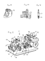
- the assembly 1 shown in the figures is arranged in the installed position in a chassis 2, which accommodates all components of the compact heating system and is attached to its rear wall 3 typically hanging on a wall or can be fixed floor-mounted or ceiling-mounted in providing a corresponding frame.
- the assembly 1 is arranged in the lower part of the chassis 2 and has four downgoing outgoing lines 4, 5, 6 and 7, which lie in a row parallel to the rear wall of the chassis 2 and to which the house-side water-carrying lines are connected.
- the upper part of the assembly 1 is, as usual in these devices, for receiving a burner and a primary heat exchanger arranged above it, these components are in Fig. 1 away.
- the assembly 1 has a right side in installation position upwards to the primary heat exchanger outgoing line 8, and a left side arranged, coming from the top of the primary heat exchanger line 9.
- a gas line 10 is guided, which is arranged in front of the unit 1 and in a likewise arranged in front of the unit 1 valve unit 11, which controls the gas supply to the burner.
- the assembly 1 has a plate heat exchanger 12, which is arranged parallel to the rear wall 3 and is tabular. In the installation position, a first sub-assembly 13 shoots from the front on the plate heat exchanger 12 and a second sub-assembly 14 on the left side.
- the sub-assemblies 13 and 14 are essentially made of plastic injection molded bodies and arranged so that their mechanical connection substantially over the existing metal Plate heat exchanger 5 takes place.
- the cable routing within the unit 1 and within the compact heating system results in detail Fig. 15 ,
- the flowing back from the return of the space heating water passes through the right in the installed position line connection in the line 7 and thus in the first sub-assembly 13, which includes, inter alia, a centrifugal pump 15 and an air separator 16.
- the line 7 opens into the suction chamber of the centrifugal pump 15, to which the air separator 16 connects at the top.
- the discharge nozzle of the pump 15 is connected to the leading to the primary heat exchanger line 8.
- the pump housing and the remaining lines of the first sub-assembly 13 are formed by an injection-molded component.
- the centrifugal pump 15 has, as usual in such units, a flanged, in the installed position accessible from the front electric motor 17, the terminal box 18 is disposed at the top of the motor housing.
- the line section 19 includes a flow diverting by 180 ° component 22, which connects the line section 19 with the right in the installed position next to it between pump 15 and line section 19 arranged right line section 20.
- the component 22 comprises a flow regulator, with which the flow rate is controlled, so that it is substantially independent of the line pressure.
- a pin-shaped actuating body 23 in the component 22 is arranged in alignment with the line section 20.
- the adjusting body has at its upper end a tool holder, here a square, with which it can be rotated about its longitudinal axis.
- the adjusting body 23 is mounted by means of a thread in the component 22, so that depending on the direction of rotation a flow-limiting provided with axis-parallel groove-like channels cone 24 more or less in an elastic receptacle 25 (see Fig. 13 ) can be inserted, which is incorporated at the upper end of the right line section 20.
- Such flow regulators are state of the art, which is why their function is not described in detail here.
- the component 22 is fastened by means of screws to the line sections 19 and 20 laterally projecting projections. If a flow rate regulator is not to be provided, the component 22 can be replaced by a 180 ° pipe bend without the injection molding component of the first substructure unit 13 adjoining it having to be changed.
- the installation in the lower end of the line section 20 is connected via an arcuately guided in the sub-assembly 13 channel line section 42 with the lower right in the installed position of the plate heat exchanger 12.
- the overlying upper port of the plate heat exchanger 12 is connected via a likewise arcuate line section 43 with the suction chamber of the pump 15.
- These line sections 42 and 43 are arc-shaped, so that they can be formed by pivot cores from the back of the sub-assembly 13, while allowing a certain lateral offset.
- the line section 42 has an opening at the bottom, which lines lead this line section 42 with a vertically downwardly leading channel 44, which formed widened down and forms a receptacle 45 for a valve 46, the valve body 47 via a from the outside between the Connection piece for the cold service water and the connection piece for the return of the heating water is arranged and accessible.
- This valve 46 has a sealing body 48 near the upper end of the valve body 47, which closes or opens the channel 44 depending on the position of the valve and then over the space formed by the receptacle 45 with a subsequent back within the sub-assembly 13 to the bypass line line and thus connects to the return side of the heating circuit.
- the sub-assembly 13 may be formed by correspondingly changing the take-up 45 and the channel 44 forming die core of the tool so that an opening between the channel 44 and the line section 42 is not formed. Then, the valve 46 is modified so that it forms only a connecting piece, which is connected depending on the position of the valve body 47 to the heating circuit or is closed off in contrast. This nozzle is then also used to fill or refill the heating circuit with water and is either fixed via a Disconnecteur, d. H.
- the right-hand conduit section 20 adjoins the lower right-hand connection of the plate heat exchanger 12 in the installed position so that the cold process water flows into the lower right-hand connection of the plate heat exchanger 12, flows through this to the lower left connection and there in a line part bent downwards through 90 ° opens, which forms at the end of the line 5 for emerging from the unit 1 warm hot water.
- This hot water is heated by heating water flowing countercurrently from the upper left port of the plate heat exchanger 12 to the upper right port.
- the upper right-hand connection is connected via a line section to the suction chamber of the pump 15 of the first sub-assembly 13.
- the emerging from the primary heat exchanger hot heat transfer medium passes through the line 9 via a line section 26, which is part of the second unit 14 and seen in the installation position extends down and behind in an arc (s. Fig. 2
- the receptacle 27 lies with its axis parallel to the plate heat exchanger 12 and at right angles askew to the impeller axis of the centrifugal pump 15.
- the recording is to the left in installation position from the left side a closure lid 29 accessible after removing the switch body can be pulled out of the receptacle side.
- the switching valve 28 is controlled by an electric servomotor 30, which is above the plate heat exchanger 12, however, arranged in front of this and the axis of rotation lies in a vertical plane in which the longitudinal axis of the receptacle 27 is seconded.
- the switching valve 28 with the associated servomotor 30 is not described in detail here, it is so far as an example EP 04 026 233 A1 referenced where such a valve is described in detail.
- the second sub-assembly 14, whose basic structure is also formed of a plastic injection molded part, thus includes the switching valve 28 with the corresponding line connections and is firmly connected to the left in the installed position line connections of the plate heat exchanger 12, thus also includes the line 5.
- the first sub-assembly 13 and the second sub-assembly 14 substantially connected to each other via the plate heat exchanger 12, but also connect other compounds, such as the bottom plate of the chassis 2 and a bypass line, but which are connected so that they in the longitudinal direction of the plate heat exchanger 12 (in installation position in horizontal Direction) are movably guided in order to avoid the introduction of thermal stresses due to different material expansions.
- a line section 31 to a bypass line 32, which connects the second sub-unit 14 with the first sub-unit 13 and laterally connected to the first sub-unit 13 in the region between plate heat exchanger 12 and the line sections 19 and 20 and thus forms a connection to the suction region of the pump 15.
- the line section 31 connects to a perpendicular thereto in the same plane extending line portion 33 which extends in addition to the plate heat exchanger 12 in alignment with it. This is angled in the installed position on the right side by 90 ° to the front and there goes into a line section 34 which is open toward the front and serves to receive a valve 35 in the form of an adjustable pressure relief valve.
- a line section 36 connects to the right, which extends parallel to the plate heat exchanger 12 in front of it.
- a back of this cantilevered support 37 comes to the bottom of the plate heat exchanger 12 to the plant.
- At this line section 36 in turn closes perpendicular to a fitting 38 receiving and thus open to the front line section on, which is designed here for example as a filling valve for filling the heating system with water.
- the right end of the line section 36 is provided with an O-ring 39 and guided only in the direction transverse to the longitudinal axis of the line section 36 in the corresponding aligned receiving the first sub-assembly 14 so that a movement in the axial direction to compensate for tolerances and thermal expansion is possible.
Abstract
Description
Die Erfindung betrifft eine Baueinheit für eine Kompaktheizungsanlage mit zwei Heizkreisen, einen für die Brauchwassererwärmung und einen für die Raumheizung.The invention relates to a unit for a compact heating system with two heating circuits, one for the domestic water heating and one for space heating.
Derartige Baueinheiten zählen zum Stand der Technik und werden eingesetzt, um die zahlreichen in einer solchen Kompaktheizungsanlage unterzubringenden Bauteile und Baugruppen aufnehmen und zusammen mit der Baueinheit als Ganzes handhaben zu können. Dabei umfasst die Baueinheit insbesondere die nahezu komplette Verrohrung des Gerätes in einem oder mehreren Kunststoffspritzgussteilen. Im letzteren Fall besteht die Baueinheit aus Teilbaueinheiten, die ihrerseits ggf. mit den zugehörigen Bauteilen bzw. Baugruppen einzeln handhabbar sind und zur Baueinheit zusammen gefügt werden. Dabei sind bei derartigen Heizungsanlagen, die sowohl für die Raumheizung als auch für die Warmwasserbereitung vorgesehen sind, typischerweise ein Plattenwärmetauscher zur Erwärmung des Brauchwassers sowie eine Heizungsumwälzpumpe vorgesehen, welche das Heizungswasser, welches in einem meist gasbetriebenen Primärwärmetauscher erwärmt wird, den Heizkreisen zuführt. Um wahlweise den einen oder anderen Heizkreis versorgen zu können, ist darüber hinaus ein Umschaltventil vorgesehen. Schließlich sind eine Vielzahl von Anschlüssen, Aufnahmeräumen für Sensorik und Leitungsverbindungen vorgesehen, die auf möglichst engem Raum fertigungstechnisch günstig realisiert werden sollen.Such units are state of the art and are used to accommodate the numerous housed in such a compact heating system components and assemblies and to be able to handle together with the unit as a whole. In this case, the assembly comprises in particular the almost complete piping of the device in one or more injection molded plastic parts. In the latter case, the assembly consists of sub-units, which in turn may be handled individually with the associated components or assemblies and joined to the assembly together. In this case, such a heating systems, which are intended for both space heating and hot water, typically a plate heat exchanger for heating the service water and a heating circulation pump is provided which supplies the heating water, which is heated in a gas-driven primary heat exchanger, the heating circuits. In order to be able to supply either one or the other heating circuit, a changeover valve is also provided. Finally, a variety of connections, receiving spaces for sensors and cable connections are provided, which are to be realized in the smallest possible space manufacturing technology low.
Eine solche Baueinheit ist beispielsweise aus
Diese Anordnung ist zwar äußerst kompakt und fertigungstechnisch vor teilhaft, hat jedoch konstruktionsbedingt auch Nachteile. So sind die Anschlussstutzen, die bei derartigen Kompaktheizungsanlagen typischerweise nach unten abgehen, über die Bodenebene zweidimensional verteilt angeordnet. Da der Plattenwärmetauscher typischerweise aus Metall, die Teilbaueinheiten sowie das Pumpengehäuse jedoch aus Kunststoff bestehen, sind bei dieser bekannten Konstruktion die Werkstoffe sorgfältig aufeinander abzustimmen, damit bei Wärmedehnungen nicht unzulässig hohe Spannungen in der Baueinheit entstehen. Auch bedingt die Konstruktion die Gasführung innerhalb der Kompaktheizungsanlage im Seitenbereich, was nicht immer gewünscht wird.Although this arrangement is extremely compact and manufacturing technology before geous, but has design-related disadvantages. Thus, the connecting pieces, which typically go down in such compact heating systems, arranged distributed over the ground plane two-dimensionally. Since the plate heat exchanger is typically made of metal, the subassemblies and the pump housing, however, made of plastic, in this known construction, the materials are carefully matched to each other so that thermal expansion does not cause unacceptably high voltages in the unit. Also, the construction requires the gas flow within the compact heating system in the side area, which is not always desired.
Insoweit günstiger sind Konstruktionen, wie sie aus
Die Zugänglichkeit des Umschaltventils und des dieses steuernden Elektromotors kann in der Praxis Probleme bereiten, da die Teilbaueinheiten in Einbaulage von der Rückseite gar nicht und von unten nur schlecht zugänglich sind. Auch soll die Konstruktion möglichst kompakt bauen, um möglichst kleine Außenabmessungen der Kompaktheizungsanlage zu ermöglichen.The accessibility of the switching valve and this controlling electric motor can cause problems in practice, since the sub-assemblies are not accessible in the installed position from the back and poorly accessible from below. Also, the construction should be as compact as possible to allow the smallest possible outside dimensions of the compact heating system.
Vor diesem Hintergrund liegt der Erfindung die Aufgabe zugrunde, eine gattungsgemäße Baueinheit zu schaffen, die die vorgenannten Nachteile weitgehend vermeidet, zumindest vermindert und die kostengünstig herstellbar ist und deren Bauteile im Einbauzustand gut zugänglich sind.Against this background, the present invention seeks to provide a generic structural unit that largely avoids the aforementioned disadvantages, at least reduced and which is inexpensive to produce and their components are easily accessible in the installed state.
Diese Aufgabe wird gemäß der Erfindung durch die in Anspruch 1 aufgeführten Merkmale gelöst. Vorteilhafte Ausgestaltungen sind in den unteransprüchen, der nachfolgenden Beschreibung und der Zeichnung dargestellt.This object is achieved according to the invention by the features listed in
Die erfindungsgemäße Baueinheit für eine Kompaktheizungsanlage mit zwei Heizkreisen, einen für die Brauchwassererwärmung und einen für die Raumheizung, weist eine erste Teilbaueinheit auf, welche eine Kreiselpumpe aufweist. Die Baueinheit ist darüber hinaus mit einem Plattenwärmetauscher ausgestattet, der in Enbaulage ein unteres Anschlusspaar und ein oberes Anschlusspaar aufweist, die jeweils über den Plattenwärmetauscher fiuidleitend miteinander verbunden sind, Eine zweite Teilbaueinheit weist ein elektrisch gesteuertes Umschaltventil zum wahlweisen Führen eines von einem Primärwärmetauscher kommenden Wärmeträgerstroms zum Heizkreis für die Raumheizung oder zum Plattenwärmetauscher auf. Die beiden Teilbaueinheiten sind mechanisch durch den Plattenwärmetauscher miteinander verbunden und schließen mindestens am oberen Anschlusspaar des Plattenwärmetauschers an. Das obere Anschlusspaar des Plattenwärmetauschers führt dabei das Heizwasser, wohingegen das untere Anschlusspaar das Brauchwasser führt.The assembly according to the invention for a compact heating system with two heating circuits, one for domestic water heating and one for space heating, has a first sub-assembly, which is a centrifugal pump having. The assembly is also equipped with a plate heat exchanger having a lower terminal pair and an upper pair of terminals in construction position, which are each connected via the plate heat exchanger fiuidleitend, a second sub-unit has an electrically controlled switching valve for selectively guiding a coming from a primary heat exchanger heat transfer to Heating circuit for space heating or plate heat exchanger on. The two sub-assemblies are mechanically interconnected by the plate heat exchanger and connect at least to the top pair of the plate heat exchanger. The upper connection pair of the plate heat exchanger leads the heating water, whereas the lower connection pair leads the hot water.
Die vorgenannten sowie auch im Weiteren genannten räumlichen Zuordnungen beziehen sich auf die Einbaulage der Baueinheit in der Heizungsanlage von vorne, also von der Bedienseite aus gesehen. Eine solche Kompaktheizungsanlage ist typischerweise wandhängend angeordnet, wobei sämtliche vier Wasseranschlüsse sowie der Gasanschluss von unten zugeführt sind. Da der Primärwärmetauscher, über den mittels einer Gasflamme das Heizwasser erhitzt wird, im oberen Teil der Kompaktheizungsanlage, also über der Baueinheit angeordnet ist, ergibt sich die Anordnung in Einbaulage zwangsläufig dergestalt, dass der Plattenwärmetauscher mit seiner Flachseite etwa wandparallel angeordnet ist, die Leitungsführung zum Primärwärmetauscher nahe der rechten und linken Seite der Anlage nach oben erfolgt und die Leltungsanschlüsse für die Raumheizung [Vor- und Rücklauf) und für das Brauchwasser (Zulauf Kaltwasser und Warmwasseranschluss) nach unten herausgeführt sind.The above-mentioned and also mentioned hereinafter spatial allocations relate to the installation position of the unit in the heating system from the front, so seen from the operating side. Such a compact heating system is typically arranged wall-mounted, with all four water connections and the gas connection are supplied from below. Since the primary heat exchanger, via which the heating water is heated by means of a gas flame, in the upper part of the compact heating system, ie arranged above the unit, the arrangement inevitably results in the installation position such that the plate heat exchanger is arranged with its flat side approximately parallel to the wall, the wiring to Primary heat exchanger near the right and left side of the system upwards and the Leltungsanschlüsse for space heating [supply and return) and for the hot water (inflow cold water and hot water supply) are led out down.
Bei der erfindungsgemäßen Ausgestaltung der Baueinheit ist die Leitungsführung so gewählt, dass das obere Anschlusspaar des Plattenwärmetauschers das Heizwasser führt, wohingegen das untere das Brauchwasser führt. Dies ist besonders vorteilhaft, da es konstruktiv eine Anschlussanordnung erleichtert, bei welcher die nach unten aus der Baueinheit heraus geführten Anschlüsse in einer Reihe etwa parallel zur Wand, an der die Kompaktheizungsanlage angeordnet ist, liegt. Bei dieser Anordnung müssen nämlich die brauchwasserführenden Anschlüsse nicht vor oder hinter den heizungswasserführenden Anschlüssen geführt werden, sondern können praktisch direkt nach unten abgeleitet werden. Auch die Leitungsführung zum Primärwärmetauscher wird vereinfacht, die aufgrund der in Einbaulage oberen Anordnung des Primärwärmetauschers zwangsläufig ebenfalls nach oben gerichtet sein muss.In the embodiment of the assembly according to the invention, the wiring is chosen so that the upper connection pair of the plate heat exchanger the heating water leads, whereas the lower leads the hot water. This is particularly advantageous because it structurally facilitates a connection arrangement in which the down out of the assembly out in a row connections approximately parallel to the wall on which the compact heating system is located, is located. In this arrangement, namely the user-water-carrying connections must not be performed in front of or behind the hot water-carrying connections, but can be derived practically directly down. The wiring to the primary heat exchanger is simplified, which must necessarily be directed upward due to the installation position in the upper arrangement of the primary heat exchanger.
Ein weiterer wesentlicher Vorteil der erfindungsgemäßen Baueinheit liegt darin, dass die Teilbaueinheiten mechanisch über den Plattenwärmetauscher verbunden sind, und zwar dergestalt, dass sie vorteilhaft nur oder im Wesentlich nur über den Plattenwärmetauscher verbunden sind. Diese Anordnung ist konstruktionsbedingt frei von Spannungen, die durch Wärmedehnung des Plattenwärmetauschers bedingt sind. Darüber hinaus kann die gesamte Baueinheit einfach und kostengünstig durch lediglich zwei Teilbaueinheiten und den ohnehin gesondert herzustellenden Plattenwärmetauscher gebildet werden. Schließlich ermöglicht die erfindungsgemäße Anordnung der Baueinheit eine zentrale Gasführung etwa in der Mitte der Kompaktheizungsanlage, da bei dieser Konstruktion in diesem Bereich ein entsprechender Freiraum gebildet werden kann.Another significant advantage of the assembly according to the invention is that the sub-assemblies are mechanically connected via the plate heat exchanger, in such a way that they are advantageous only or substantially only connected via the plate heat exchanger. This arrangement is by design free of stresses that are caused by thermal expansion of the plate heat exchanger. In addition, the entire unit can be easily and inexpensively formed by only two sub-assemblies and the already separately produced plate heat exchanger. Finally, the arrangement of the assembly according to the invention enables a central gas guide approximately in the middle of the compact heating system, since in this construction, a corresponding clearance can be formed in this area.
Bei modernen Kompaktheizungsanlagen hat sich ein elektrisch gesteuertes Umschaltventil bewährt, welches eine im Wesentlichen zylindrische Aufnahme für mindestens einen, typischerweise aber zwei bewegbare Schaltkörper aufweist. Diese Schaltkörper sitzen auf einer Schaltstange, welche elektromotorisch verfahrbar ist.In modern compact heating systems, an electrically controlled switching valve has proven to have a substantially cylindrical receptacle for at least one, but typically two movable switch body. These switch body sit on a shift rod, which is moved by an electric motor.
Gemäß der Erfindung ist der Schaltkörper elektromotorisch bewegbar und der Elektromotor in Einbaulage über der Aufnahme für den Schaltkörper angeordnet. Dabei ist der zum Primärwärmetauscher führende Anschlussstutzen des Umschaltventils in Einbaulage nach vorne gerichtet. Bei dieser Anordnung ist in Einbaulage der zum Primärwärmetauscher führende Anschlussstutzen des Umschaltventils besonders gut zugänglich, der Elektromotor liegt dabei geschützt über den flüssigkeitsführenden Bauteilen der Baueinheit.According to the invention, the switch body is movable by an electric motor and the electric motor is arranged in the installed position over the receptacle for the switch body. Here, the leading to the primary heat exchanger connecting piece of the changeover valve is directed in the installed position to the front. In this arrangement, in the installed position leading to the primary heat exchanger connecting piece of the changeover valve is particularly accessible, the electric motor is protected by the liquid-carrying components of the assembly.
Gemäß der Erfindung ist die zylindrische Aufnahme des Umschaltventils dabei vorteilhaft so angeordnet, dass diese in Einbaulage vor dem Plattenwärmetauscher und mit ihrer Längsmittelachse parallel dazu angeordnet ist. Eine solche Anordnung ist ungewöhnlich und bietet konstruktive, fertigungstechnische und anschlusstechnische Vorteile. Es ist insbesondere damit möglich, ohne verlorene Kerne einen von der Aufnahme nach unten abgehenden Vorlaufanschluss für die Raumheizung zu schaffen. Dabei ist die Anordnung vorteilhaft so, dass die Längsmittelachse der Aufnahme in einem rechten Winkel windschief zur Laufachse der Kreiselpumpe angeordnet ist.According to the invention, the cylindrical receptacle of the switching valve is advantageously arranged so that it is arranged in the installed position in front of the plate heat exchanger and with its longitudinal central axis parallel thereto. Such an arrangement is unusual and offers design, manufacturing and technical advantages. In particular, it is thus possible, without lost cores, to create a supply connection for the space heating, which leads downwards from the receptacle. In this case, the arrangement is advantageous in that the longitudinal central axis of the receptacle is arranged at a right angle askew to the running axis of the centrifugal pump.
Gemäß einer vorteilhaften Weiterbildung der Erfindung weist die Aufnahme einen stirnseitigen Verschluss auf. über den der oder die Schaltkörper zugänglich sind und der in Einbaulage von der Seite zugänglich ist. Vorteilhaft ist die Anordnung so, dass bis zur seitlichen Verkleidung der Kompaktheizungsanlage ein ausreichender Freiraum verbleibt, der ein Entfernen oder Austauschen des Schaltkörpers ohne Probleme ermöglicht.According to an advantageous embodiment of the invention, the receptacle on an end-side closure. over which the switch body or the switch body are accessible and which is accessible in the installed position from the side. Advantageously, the arrangement is such that remains until the side panel of the compact heating system sufficient clearance that allows removal or replacement of the switch body without problems.
Auch wenn die mechanische Verbindung der Teilbaueinheiten durch den Plattenwärmetauscher erfolgt, so kann es je nach Auslegung der Heizungsanlage erforderlich sein, weltere Leitungsverbindungen zwischen den Teilbaueinheiten vorzusehen, so typischerweise einen Bypass zwischen Vor- und Rücklauf. Gemäß einer Weiterbildung der Erfindung wird ein solcher Bypass vorteilhaft durch einen in Einbaulage vor dem Plattenwärmetauscher angeordneten Rohrabschnitt gebildet, welcher die Teilbaueinheiten entsprechend miteinander leitungsverbindet. Dabei sollte der Rohrabschnitt möglichst parallel zur Längsmittelachse des Plattenwärmetauschers liegen und teleskopierbar ausgebildet sein, sodass zum einen Toleranzen des Plattenwärmetauschers hinsichtlich des Abstandes der Anschlüsse eines Anschlusspaares auf einfache Weise ausgeglichen werden können, andererseits Wärmedehnungen des typischerweise metallischen Plattenwärmetauschers gegenüber den sonst typischerweise aus Kunststoffspritzguss bestehenden Teilbaueinheiten ausgeglichen werden können. Die Teleskopierbarkeit kann in einfacher Weise durch ineinander gesteckte Rohrabschnitte mit dazwischen liegender Dichtung, beispielsweise eines O-Rings gewährleistet werden.Even if the mechanical connection of the sub-assemblies takes place through the plate heat exchanger, depending on the design of the heating system it may be necessary to provide world-wide cable connections between to provide the sub-assemblies, so typically a bypass between flow and return. According to one embodiment of the invention, such a bypass is advantageously formed by an arranged in the installed position in front of the plate heat exchanger pipe section, which line interconnects the sub-assemblies accordingly. In this case, the pipe section should be as parallel to the longitudinal central axis of the plate heat exchanger and telescopic, so on the one tolerances of the plate heat exchanger with respect to the distance of the terminals of a terminal pair can be compensated in a simple way, on the other hand thermal expansions of the typically metallic plate heat exchanger compared to the otherwise typically made of plastic injection molding sub-assemblies can be compensated. The telescoping can be ensured in a simple manner by nested pipe sections with intermediate seal, such as an O-ring.
Gemäß einer Weiterbildung der Erfindung ist die Bypassleitung mit einer zweifachen Abwinklung versehen, wobei ein im Wesentlichen senkrecht zum Plattenwärmetauscher angeordneter Teil ein in Einbaulage von vorne vorzugsweise zwischen zwei Anschlussstutzen der Baueinheit zugänglichen und den Durchfluss durch den Bypass beeinflussenden Stellmechanismus aufnimmt. Ein solcher Stellmechanismus kann dann vorteilhaft von vorne eingegliedert werden und ist auch in Einbaulage gut zugänglich.According to one embodiment of the invention, the bypass line is provided with a double bend, wherein a substantially perpendicular to the plate heat exchanger part receives in an installed position from the front preferably between two connecting pieces of the unit accessible and influencing the flow through the bypass actuator mechanism. Such an adjustment mechanism can then be advantageously incorporated from the front and is easily accessible even in the installed position.
Vorteilhaft kann in dem parallel zum Wärmetauscher angeordneten vorderen Rohrabschnitt mindestens ein weiterer Anschluss vorgesehen sein, beispielsweise zur Eingliederung eines Sensors. Dies ist besonders günstig, da zum einen dieser Bereich in Einbaulage besonders gut zugänglich ist, zum anderen werkzeugtechnisch wenig kompliziert zu realisieren ist, sodass durch das Vorsehen eines solchen weiteren Anschlusses die Werkzeugkosten nur unwesentlich erhöht werden.Advantageously, at least one further connection can be provided in the front pipe section arranged parallel to the heat exchanger, for example for the integration of a sensor. This is particularly favorable, since on the one hand this area is particularly well accessible in the installed position, and on the other hand, it is difficult to implement in terms of tool technology, so that the provision of such a further connection increases the tool costs only insignificantly.
Gemäß einer vorteilhaften Weiterbildung der Erfindung weist die erste Teilbaueinheit einen Durchflussmengenregler auf, der vorteilhaft in einem gemeinsamen Gehäuse mit der Kreiselpumpe angeordnet ist. Ein solcher Durchflussmengenregler ist für das durch die Baueinheit durchströmende und zu erwärmende Brauchwasser vorgesehen und arbeitet typischerweise mechanisch, kann jedoch auch über eine elektronische Regelung elektrisch gesteuert sein, in Form eines Stellventils. Ein solcher Durchflussmengenregler sorgt dafür, dass unabhängig vom Leitungsdruck stets im Wesentlichen die gleiche Menge durchfließt, wenn das Brauchwasserentnahmeventil vollständig geöffnet ist. Hierdurch wird insbesondere sichergestellt, dass bei zu hohem Leitungsdruck das Brauchwasser im Plattenwärmetauscher noch auf die gewünschte Temperatur erwärmt werden kann, d.h. dass nach Möglichkeit stets Wasser mit derselben Temperatur entnommen werden kann. Dabei ist vorteilhaft gemäß der Erfindung der Durchflussmengenregler in einem gemeinsamen Gehäuse mit der Kreiselpumpe angeordnet. Ein solches Gehäuse kann ein- oder mehrteilig aufgebaut sein, bei einem mehrteiligen Aufbau ergibt sich der Vorteil, dass die gleiche Baueinheit wahlweise mit oder ohne Durchflussmengenregler erstellt werden kann, ohne größere bauliche Änderungen vorzunehmen.According to an advantageous development of the invention, the first subassembly has a flow rate regulator, which is advantageously arranged in a common housing with the centrifugal pump. Such a flow regulator is provided for the service water flowing through the unit and to be heated and typically operates mechanically, but may also be electrically controlled via an electronic control, in the form of a control valve. Such a flow regulator ensures that, regardless of the line pressure, essentially the same amount flows through when the service water extraction valve is fully opened. This ensures in particular that at too high line pressure the Hot water in the plate heat exchanger can still be heated to the desired temperature, ie that whenever possible water can be removed at the same temperature. It is advantageous according to the invention, the flow regulator arranged in a common housing with the centrifugal pump. Such a housing may be constructed in one or more parts, in a multi-part design there is the advantage that the same unit can be created either with or without flow regulator, without making major structural changes.
Vorteilhaft sind in der ersten Teilbaueinheit nebeneinander angeordnete Leitungsabschnitte vorgesehen, die durch ein zumindest Teile des Durchflussmengenreglers aufweisendes Bauteil miteinander leitungsverbunden sind, in dem die Strömung um etwa 180° umgelenkt wird. Ein solches Bauteil kann für eine vereinfachte Ausführung ohne Regler in einfacher Weise durch einen 180°-Rohrkrümmer ersetzt werden, ohne die Konstruktion und damit das Spritzgusswerkzeug bzw. die Spritzgusswerkzeuge für die erste Teilbaueinheit ändern zu müssen.Advantageously, in the first sub-assembly side by side arranged pipe sections are provided which are interconnected by a component having at least parts of the flow regulator, in which the flow is deflected by about 180 °. Such a component can be easily replaced by a 180 ° elbow manifold for a simplified design without a regulator, without having to change the construction and thus the injection molding tool or the injection molding tools for the first sub-assembly.
Die Leitungsabschnitte sind vorteilhaft so angeschlossen, dass einer der Leitungsabschnitte an den Wärmetauscher und der andere Leitungsabschnitt bevorzugt an einen in Einbaulage unteren Anschluss der Baueinheit anschließt oder diesen bildet. Dabei weist der nicht an den Wärmetauscher anschließende Leitungsabschnitt vorteilhaft einen Durchflussmesser auf. Vorteilhaft ist hier ein nach dem Vortex-Prinzip arbeitender Durchflussmesser eingegliedert, wobei der Leitungsabschnitt so ausgebildet ist, dass vor der Obstruktion, welche die Schwingung der Strömung auslöst, eine ausreichende Strecke zur Beruhigung der Strömung und nach der Obstruktion eine ausreichende Messstrecke gebildet ist, damit sich die strömungsgeschwindigkeitsabhöngige Schwingung ausbilden und durch einen Drucksensor bzw. Differenzdrucksensor erfasst werden kann. Hierzu ist es zweckmäßig, den Durchflussmesser nahe dem in Durchflussrichtung gesehenen Anfang des Leitungsabschnitts anzuordnen, d.h. in Durchflussrichtung mit ausreichendem Abstand vor dem Durchflussmengenregler.The line sections are advantageously connected in such a way that one of the line sections adjoins the heat exchanger and the other line section preferably adjoins or forms a lower connection of the building unit in the installed position. In this case, the non-adjoining the heat exchanger line section advantageously has a flow meter. Advantageously, a flow meter operating according to the vortex principle is incorporated here, wherein the line section is designed so that a sufficient distance for calming the flow and after the obstruction a sufficient measuring section is formed before the obstruction which triggers the oscillation of the flow the flow rate-dependent vibration can form and can be detected by a pressure sensor or differential pressure sensor. For this purpose, it is expedient, the flow meter to arrange near the beginning of the line section seen in the direction of flow, ie in the direction of flow with sufficient distance in front of the flow regulator.
Zweckmäßigerweise sind die vorgenannten Leitungsabschnitte nebeneinander angeordnet, und zwar so, dass sie in Einbaulage etwa senkrecht und nebeneinander vor dem Plattenwärmetauscher neben der Kreiselpumpe angeordnet sind. Solche parallelen Leitungsabschnitte sind fertigungstechnisch besonders günstig, da sie mit einfachen Ziehkernen hergestellt werden können. Ebenso verhält es sich mit den senkrecht zu den Leitungsabschnitten vorzusehenden Anschlüssen, sei es zum Plattenwärmetauscher oder auch zur Aufnahme des Durchflussmengenmessers.Appropriately, the aforementioned line sections are arranged side by side, in such a way that they are arranged in the installed position approximately perpendicular and side by side in front of the plate heat exchanger next to the centrifugal pump. Such parallel line sections are particularly favorable in terms of production since they can be produced with simple drawing cores. The same applies to the connections to be provided perpendicular to the line sections, be it to the plate heat exchanger or to accommodate the flow meter.
Vorteilhaft weist der vom Durchflussmengenregler zum Plattenwärmetauscher führende Leitungsabschnitt eine Durchbrechung auf, die mit der Saugseite der Pumpe leitungsverbunden ist. Die so gebildete Verbindung mit der Saugseite der Pumpe kann dann zur Eingliederung eines Absperrventils dienen, über das die Heizungsanlage befüllt werden kann, ohne hierfür eine gesonderte Leitungsverbindung vorsehen zu müssen. Da dies nicht in allen Ländern zulässig ist, kann alternativ die Teilbaueinheit auch ohne Durchbrechung ausgebildet sein, was durch geringfügige Änderung des Werkzeugs möglich ist, wobei dann vorteilhaft ein Absperrventil und ein Anschlussstutzen an dieser Teilbaueinheit vorgesehen ist und an der anderen Teilbaueinheit ebenfalls ein Anschlussstutzen mit Absperrventil, jedoch zur Brauchwasserleitung. Diese können je nach Zulässigkeit zum Befüllen der Heizungsanlage mit einem Schlauch verbunden werden oder stationär mit einem Disconnecteur ständig verbunden sein, welcher zusätzlich ein Rückschlagventil aufweist, um sicherzustellen, dass kein Wasser aus der Heizungsanlage in die Brauchwasserleitung zurückfließen kann.Advantageously, the line section leading from the flow regulator to the plate heat exchanger has an opening which is conductively connected to the suction side of the pump. The connection thus formed with the suction side of the pump can then serve for the integration of a shut-off valve, via which the heating system can be filled without having to provide a separate line connection for this purpose. Since this is not permitted in all countries, alternatively, the sub-assembly may also be formed without opening, which is possible by slight change of the tool, in which case advantageously a shut-off valve and a connecting piece is provided on this sub-assembly and on the other sub-assembly also with a connecting piece Shut-off valve, but for service water. These can be connected depending on the admissibility to fill the heating system with a hose or stationary connected to a Disconnecteur, which additionally has a check valve to ensure that no water from the heating system can flow back into the service water pipe.
Zur Eingliederung des vorgenannten Ventils ist es vorteilhaft, wenn die Durchbrechung in eine vorzugsweise unten offene Ventilkammer (in Einbaulage) mündet, die zur Aufnahme eines Ventilkörpers vorgesehen ist, mit dem entweder die Leitungsverbindung zwischen der Brauchwasserleitung und der Heizleitung unterbrochen bzw. verbunden werden kann oder aber die Leitungsverbindung zwischen dem Anschlussstutzen und der Heizleitung hergestellt bzw. unterbrochen werden kann.For incorporation of the aforementioned valve, it is advantageous if the opening opens into a preferably open at the bottom valve chamber (in installation position), which is provided for receiving a valve body with which either the line connection between the service water pipe and the heating cable can be interrupted or connected or but the line connection between the connecting piece and the heating cable can be made or interrupted.
Die Erfindung ist nachfolgend anhand eines in der Zeichnung dargestellten Ausführungsbeispiels näher erläutert. Es zeigen:
- Fig. 1
- in perspektivischer vereinfachter Darstellung eine erfindungsgemäße Baueinheit in Einbaulage im Chassis einer Kompaktheizungsanlage,
- Fig. 2
- eine perspektivische Ansicht der Baueinheit,
- Fig. 3
- eine Draufsicht auf die Baueinheit,
- Fig. 4
- eine Ansicht von vorne auf die Baueinheit,
- Fig. 5
- eine Ansicht von der ein Einbaulage rechten Seite auf die Baueinheit,
- Fig. 6
- eine Ansicht von der in Einbaulage linken Seite auf die Baueinheit,
- Fig. 7
- die einen Bypass bildenden und die Teilbaueinheiten verbindenden Bauteile in perspektivischer Darstellung,
- Fig. 8
- eine Ansicht auf die Bauteile gemäß
Fig. 7 in Einbaulage gesehen von vorne, - Fig. 9
- einen Schnitt längs der Linie A-A in
Fig. 8 , - Fig. 10
- eine perspektivische Ansicht des Druckreglers,
- Fig. 11
- den Druckregler gemäß
Fig. 10 im Schnitt, - Fig. 12
- den Stellkörper des Druckreglers in Ansicht,
- Fig. 13
- einen Längsschnitt durch die parallel nebeneinander verlaufenden Leitungsabschnitte der ersten Teilbaueinheit,
- Fig. 14
- einen Längsschnitt durch die erste Teilbaueinheit im Bereich der Anschlussstutzen und
- Fig. 15
- ein hydraulisches Schaltbild der Heizungsanlage mit Baueinheit.
- Fig. 1
- in perspective simplified representation of an assembly according to the invention in the installed position in the chassis of a compact heating system,
- Fig. 2
- a perspective view of the unit,
- Fig. 3
- a plan view of the unit,
- Fig. 4
- a view from the front of the unit,
- Fig. 5
- a view from the one installation position right side on the unit,
- Fig. 6
- a view from the left in the mounting position on the unit,
- Fig. 7
- the components forming a bypass and connecting the sub-assemblies in a perspective view,
- Fig. 8
- a view of the components according to
Fig. 7 seen in installation position from the front, - Fig. 9
- a section along the line AA in
Fig. 8 . - Fig. 10
- a perspective view of the pressure regulator,
- Fig. 11
- the pressure regulator according to
Fig. 10 on average, - Fig. 12
- the actuator of the pressure regulator in view,
- Fig. 13
- a longitudinal section through the parallel adjacent line sections of the first sub-assembly,
- Fig. 14
- a longitudinal section through the first sub-assembly in the region of the connecting piece and
- Fig. 15
- a hydraulic circuit diagram of the heating system with unit.
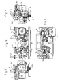
Die anhand der Figuren dargestellte Baueinheit 1 ist in Einbaulage in einem Chassis 2 angeordnet, welches sämtliche Bauteile der Kompaktheizungsanlage aufnimmt und mit seiner Rückwand 3 typischerweise an einer Wand hängend befestigt ist oder bei Vorsehen eines entsprechenden Gestells auch bodenstehend bzw. deckenhängend befestigt sein kann. Die Baueinheit 1 ist im unteren Teil des Chassis 2 angeordnet und weist vier nach unten abgehende Leitungen 4, 5, 6 und 7 auf, die in einer Reihe parallel zur Rückwand des Chassis 2 liegen und an welche die hausseitigen wasserführenden Leitungen angeschlossen werden. Der obere Teil der Baueinheit 1 ist, wie bei diesen Geräten üblich, zur Aufnahme eines Brenners sowie eines darüber angeordneten Primärwärmetauschers vorgesehen, diese Bauteile sind in
Die Baueinheit 1 weist einen Plattenwärmetauscher 12 auf, der parallel zur Rückwand 3 angeordnet ist und tafelförmig ausgebildet ist. An den Plattenwärmetauscher 12 schießt in Einbaulage rechtsseitig von vorne eine erste Teilbaueinheit 13 an sowie linksseitig eine zweite Teilbaueinheit 14. Die Teilbaueinheiten 13 und 14 sind im Wesentlichen aus Grundkörpern aus Kunststoffspritzguss gefertigt und so angeordnet, dass ihre mechanische Verbindung im Wesentlichen über den aus Metall bestehenden Plattenwärmetauscher 5 erfolgt.The
Die Leitungsführung innerhalb der Baueinheit 1 sowie innerhalb der Kompaktheizungsanlage ergibt sich im Einzelnen aus
In Einbaulage von vorne (
An das obere Ende des Leitungsabschnitts 19 schließt ein die Strömung um 180° umlenkendes Bauteil 22 an, das den Leitungsabschnitt 19 mit dem in Einbaulage rechts daneben zwischen Pumpe 15 und Leitungsabschnitt 19 angeordneten rechten Leitungsabschnitt 20 verbindet. Das Bauteil 22 umfasst einen Durchflussmengenregler, mit dem die Durchflussmenge geregelt wird, sodass diese im Wesentlichen unabhängig vom Leitungsdruck ist. Hierzu ist ein zapfenförmiger Stellkörper 23 im Bauteil 22 fluchtend zum Leitungsabschnitt 20 angeordnet. Der Stellkörper weist an seinem oberen Ende eine Werkzeugaufnahme auf, hier einen Vierkant, mit dem er um seine Längsachse gedreht werden kann. Der Stellkörper 23 ist mittels eines Gewindes im Bauteil 22 gelagert, sodass je nach Drehrichtung ein den Durchfluss begrenzender mit achsparallelen nutähnlichen Kanälen versehener Konus 24 mehr oder weniger weit in eine elastische Aufnahme 25 (siehe
Das in Einbaulage untere Ende des Leitungsabschnitts 20 ist über einen bogenförmig in der Teilbaueinheit 13 geführten Kanalleitungsabschnitt 42 mit dem in Einbaulage unteren rechten Anschluss des Plattenwärmetauschers 12 verbunden. Der darüber liegende obere Anschluss des Plattenwärmetauschers 12 ist über einen ebenfalls bogenförmig ausgebildeten Leitungsabschnitt 43 mit dem Saugraum der Pumpe 15 verbunden. Diese Leitungsabschnitte 42 und 43 sind bogenförmig ausgebildet, so dass sie durch Schwenkkerne von der Rückseite der Teilbaueinheit 13 aus gebildet werden können, gleichzeitig jedoch einen gewissen seitlichen Versatz erlauben.The installation in the lower end of the
Der Leitungsabschnitt 42 weist nach unten hin eine Durchbrechung auf, welche diesen Leitungsabschnitt 42 mit einem senkrecht nach unten führenden Kanal 44 leitungsverbindet, der nach unten hin aufgeweitet ausgebildet und eine Aufnahme 45 für ein Ventil 46 bildet, dessen Ventilkörper 47 über ein von außen zwischen dem Anschlussstutzen für das kalte Brauchwasser und dem Anschlussstutzen für den Rücklauf des Heizungswassers angeordnet und zugänglich ist. Dieses Ventil 46 weist einen Dichtkörper 48 nahe dem oberen Ende des Ventilkörpers 47 auf, welcher je nach Stellung des Ventils den Kanal 44 verschließt oder öffnet und dann über den durch die Aufnahme 45 gebildeten Raum mit einer rückseitig innerhalb der Teilbaueinheit 13 an die Bypassleitung anschließenden Leitung und somit mit der Rücklaufseite des Heizkreises verbindet. Mittels dieses Ventils 46 kann die Brauchwasserleitung mit dem Heizkreis verbunden werden, um den Heizkreis zu befüllen oder nachzufüllen.The
Alternativ kann die Teilbaueinheit 13 durch entsprechende Änderung des die Aufnahme 45 und den Kanal 44 bildenden Ziehkerns des Werkzeugs so ausgebildet werden, dass eine Durchbrechung zwischen dem Kanal 44 und dem Leitungsabschnitt 42 nicht gebildet ist. Dann ist das Ventil 46 so modifiziert, dass es lediglich einen Anschlussstutzen bildet, der je nach Stellung des Ventilkörpers 47 mit dem Heizkreis verbunden ist oder demgegenüber abgesperrt ist. Dieser Stutzen dient dann ebenfalls zum Befüllen bzw. Nachfüllen des Heizkreises mit Wasser und ist entweder fest über einen Disconnecteur, d. h. über eine Leitung mit darin befindlichem Rückschlagventil mit der Brauchwasserseite der anderen, in Einbaulage linken Teilbaueinheit 14 verbunden oder über eine schlauchartige Leitung mit einem entsprechenden Anschluss an der Teilbaueinheit 14, der dort ebenfalls mit einem Absperrventil ausgestattet ist.Alternatively, the sub-assembly 13 may be formed by correspondingly changing the take-
Der rechte Leitungsabschnitt 20 schließt an dem in Einbaulage unteren rechten Anschluss des Plattenwärmetauschers 12 an, sodass das kalte Brauchwasser an dem unteren rechten Anschluss des Plattenwärmetauschers 12 in diesen einströmt, diesen zum unteren linken Anschluss durchströmt und dort in einem um 90° nach unten abgebogenen Leitungsteil mündet, welches am Ende die Leitung 5 für das aus der Baueinheit 1 austretende warme Brauchwasser bildet. Erwärmt wird dieses Brauchwasser durch im Gegenstrom von dem oberen linken Anschluss des Plattenwärmetauschers 12 zum oberen rechten Anschluss strömendes Heizwasser. Der obere rechte Anschluss ist über einen Leitungsabschnitt mit dem Saugraum der Pumpe 15 der ersten Teilbaueinheit 13 verbunden.The right-
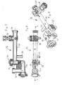
Das aus dem Primärwärmetauscher austretende heiße Wärmeträgermedium gelangt durch die Leitung 9 über einen Leitungsabschnitt 26, welcher Teil der zweiten Baueinheit 14 ist und der sich in Einbaulage gesehen nach unten und hinten in einen Bogen erstreckt (s.
Mittig in der Aufnahme 27 mündet der Leitungsabschnitt 26, der je nach Schaltstellung des Schaltkörpers des Umschaltventils 28 die vom Primärwärmetauscher kommende Leitung 9 mit der Leitung 4 für den Vorlauf der Raumheizung oder mit dem in Einbaulage oberen linken Anschluss des Plattenwärmetauschers 12 zur Erhitzung des Brauchwassers verbindet. Entsprechend schließt die Leitung 4 nahe der offenen Stirnseite der Aufnahme 27 im Wesentlichen nach unten an diese an, wohingegen der Leitungsabschnitt 26 daneben, im Wesentlichen von oben und vorne und die zum Plattenwärmetauscher 12 führende Leitung nahe dem geschlossenen Ende der Aufnahme 27 anschließt.Center of the
Das Umschaltventil 28 wird von einem elektrischen Stellmotor 30 gesteuert, der oberhalb des Plattenwärmetauschers 12 jedoch vor diesem angeordnet ist und dessen Drehachse in einer vertikalen Ebene liegt, in der auch die Längsachse der Aufnahme 27 abgeordnet ist. Das Umschaltventil 28 mit dem zugehörigen Stellmotor 30 ist hier nicht im Einzelnen beschrieben, es wird insoweit beispielhaft auf
Die zweite Teilbaueinheit 14, deren Grundaufbau ebenfalls aus einem Kunststoffspritzgussteil gebildet ist, umfasst somit das Umschaltventil 28 mit den entsprechenden Leitungsanschlüsse und ist mit den in Einbaulage linksseitigen Leitungsanschlüssen des Plattenwärmetauschers 12 fest verbunden, sie umfasst somit auch die Leitung 5. Mechanisch sind die erste Teilbaueinheit 13 und die zweite Teilbaueinheit 14 im Wesentlichen über den Plattenwärmetauscher 12 miteinander verbunden, gleichwohl auch andere Verbindungen, wie beispielsweise die Bodenplatte des Chassis 2 sowie eine Bypassleitung verbinden, die jedoch so verbunden sind, dass sie in Längsrichtung des Plattenwärmetauschers 12 (in Einbaulage in horizontaler Richtung) bewegbar geführt sind, um das Einbringen von Wärmspannungen aufgrund unterschiedlicher Materialdehnungen zu vermeiden.The second sub-assembly 14, whose basic structure is also formed of a plastic injection molded part, thus includes the switching
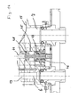
An die Leitung 4 für den Vorlauf der Raumheizung schließt rückseitig mit einem Leitungsabschnitt 31 eine Bypassleitung 32 an, die die zweite Teilbaueinheit 14 mit der ersten Teilbaueinheit 13 verbindet und seitlich an die erste Teilbaueinheit 13 im Bereich zwischen Plattenwärmetauscher 12 und den Leitungsabschnitten 19 und 20 anschließt und somit eine Verbindung zum Saugbereich der Pumpe 15 bildet. Der Leitungsabschnitt 31 schließt an einen senkrecht dazu in gleicher Ebene verlaufenden Leitungsabschnitt 33 an, der neben den Plattenwärmetauscher 12 in Flucht dazu verläuft. Dieser ist in Einbaulage rechtsseitig um 90° nach vorne abgewinkelt und geht dort in einen Leitungsabschnitt 34 über, der nach vorne hin offen ausgebildet ist und zur Aufnahme einer Armatur 35 in Form eines einstellbaren Druckbegrenzungsventils dient. Nahe dem vorderen Ende des Leitungsabschnitts 34 schließt nach rechts ein Leitungsabschnitt 36 an, der vor dem Plattenwärmetauscher 12 parallel dazu verläuft. Eine rückseitig von diesem auskragende Stütze 37 kommt an der Unterseite des Plattenwärmetauschers 12 zur Anlage. An diesem Leitungsabschnitt 36 schließt wiederum senkrecht dazu ein eine Armatur 38 aufnehmender und somit nach vorne offener Leitungsabschnitt an, der hier beispielsweise als Füllventil zum Befüllen der Heizungsanlage mit Wasser ausgebildet ist. Das rechte Ende des Leitungsabschnitts 36 ist mit einem O-Ring 39 versehen und lediglich in Richtung quer zur Längsachse des Leitungsabschnitts 36 in der entsprechend dazu fluchtenden Aufnahme der ersten Teilbaueinheit 14 geführt, sodass eine Bewegung in Achsrichtung zum Ausgleich von Toleranzen und Wärmedehnungen möglich ist.To the
- 1 -1 -
- Baueinheitunit
- 2 -2 -
- Chassischassis
- 3 -3 -
- Rückwandrear wall
- 4 -4 -
- Leitung für den HeizungsvorlaufLine for the heating flow
- 5 -5 -
- Leitung für das warme BrauchwasserHead for the hot service water
- 6 -6 -
- Leitung für das kalte BrauchwasserLine for the cold process water
- 7 -7 -
- Leitung für den HeizungsrücklaufLine for the heating return
- 8 -8th -
- Leitung zum PrimärwärmetauscherLine to the primary heat exchanger
- 9 -9 -
- Leitung vom PrimärwärmetauscherLine from the primary heat exchanger
- 10 -10 -
- Gasleitunggas pipe
- 11 -11 -
- Ventileinheitvalve unit
- 12 -12 -
- PlattenwärmetauscherPlate heat exchanger
- 13 -13 -
- erste Teilbaueinheitfirst sub-assembly
- 14 -14 -
- zweite Teilbaueinheitsecond sub-assembly
- 15 -15 -
- Kreiselpumperotary pump
- 16 -16 -
- Luftabscheiderair separator
- 17 -17 -
- Elektromotorelectric motor
- 18 -18 -
- Klemmenkastenterminal box
- 19 -19 -
- Leitungsabschnitt links vertikalLine section left vertical
- 20 -20 -
- Leitungsabschnitt rechts vertikalLine section right vertical
- 21 -21 -
- Sensoreinheit VortexSensor unit Vortex
- 22 -22 -
- Bauteilcomponent
- 23 -23 -
- Stellkörperadjusting body
- 24 -24 -
- Konuscone
- 25 -25 -
- elastische Aufnahmeelastic absorption
- 26 -26 -
- Leitungsabschnittline section
- 27 -27 -
- Aufnahme des UmschaltventilsRecording of the changeover valve
- 28 -28 -
- Umschaltventilswitching valve
- 29 -29 -
- Verschlussdeckelcap
- 30 -30 -
- Stellmotorservomotor
- 31 -31 -
- Leitungsabschnittline section
- 32 -32 -
- Bypassleitungbypass line
- 33 -33 -
- Leitungsabschnittline section
- 34 -34 -
- Leitungsabschnittline section
- 35 -35 -
- Armaturfitting
- 36 -36 -
- Leitungsabschnittline section
- 37 -37 -
- Stützesupport
- 38 -38 -
- Armaturfitting
- 39 -39 -
- O-RingO-ring
- 40 -40 -
- Obstruktionobstruction
- 41 -41 -
- DifferenzdrucksensorDifferential Pressure Sensor
- 42 -42 -
- Leitungsabschnittline section
- 43 -43 -
- Leitungsabschnittline section
- 44 -44 -
- Kanalchannel
- 45 -45 -
- Aufnahmeadmission
- 46 -46 -
- VentilValve
- 47 -47 -
- Ventilkörpervalve body
- 48 -48 -
- Dichtkörpersealing body
Claims (15)
- A construction unit for a compact heating installation with two heating circuits, one for service water heating and one for room heating, with a first part-construction-unit (13) which comprises a centrifugal pump (15), with a plate heat exchanger (12) with a connection pair which is at the bottom in the installed position and with a connection pair which is at the top in the installed position, said connection pairs being connected to one another in a fluid-leading manner in each case via the plate heat exchanger (12), and with a second part-construction-unit (14) which comprises an electrically controlled switch-over valve (28) for the selective leading of a heat transfer flow coming from a primary heat exchanger to the heating circuit for the room heating or to the plate heat exchanger (12), wherein the part-construction-units (13, 14) are mechanically connected to one another by way of the plate heat exchanger (12) and connect at least on the upper connection pair of the plate heat exchanger (12) leading the heating water, and the switch-over valve (28) comprises a switch body which is arranged in an essentially cylindrical receiver (27) and is electromotorically movable, characterised in that the electric motor (30) in the installed position is arranged above the receiver (27) for the switch body, and the switch-over valve (28) comprises a connection which leads to the primary heat exchanger and which is directed to the front in the installed position.
- A construction unit according to claim 1, with which the receiver (27) is arranged in a manner such that in the installed position it is arranged in front of the plate heat exchanger (12) and with its longitudinal middle axis is arranged essentially parallel thereto.
- A construction unit according to one of the preceding claims, with which the longitudinal middle axis of the receiver (27) is arranged at right angles in a skew manner to the impeller axis of the centrifugal pump (15).
- A construction unit according to one of the preceding claims, with which the receiver (27) comprises a face-side closure (29) which is accessible from the side in the installed position.
- A construction unit according to one of the preceding claims, with which the part- construction-units (13, 14) are connected by way of a pipe section (36) which is arranged in front of the plate heat exchanger (12) in the installed position and which forms a bypass (32) between the feed and the return.
- A construction unit according to claim 5, with which the bypass is formed telescopically in a pipe section (36) arranged parallel to the heat exchanger (12).
- A construction unit according to claim 5 or 6, with which the pipe section (32) has a double angling, wherein a part (34) arranged essentially perpendicular to the plate heat exchanger (12) receives a regulation mechanism (35) which in the installed position is accessible from the front preferably between two connection nozzles of the construction unit (1) and influences the flow through the bypass (32).
- A construction unit according to one of the preceding claims, with which the bypass (32) in particular in a pipe section (36) arranged parallel to the heat exchanger (12) comprises at least one further connection.
- A construction unit according to one of the preceding claims, with which the first part-construction-unit (13) comprises a flow rate regulator (24, 25) preferably in a common housing with the centrifugal pump (15).
- A construction unit according to one of the preceding claims, with which conduit sections (19, 20) arranged next to one another are provided in the first part-construction-unit (13) and are conduit-connected to one another by way of a component (22) which comprises at least parts of the flow rate regulator (24, 25) and in which the flow is deflected by about 180°.
- A construction unit according to claim 10, with which the one conduit section (20) connects to the heat exchanger (12), and the other conduit section (19) comprises a flowmeter (40, 41).
- A construction unit according to claim 11, with which the flowmeter (40, 41) is one operating according to the vortex principle and is arranged in the flow direction close to the beginning of the other conduit section (19).
- A construction unit according to one of the claims 10 to 12, with which the conduit sections (19, 20) which are arranged next to one another, in the installed position are arranged roughly perpendicularly in front of the plate heat exchanger (12) and next to the centrifugal pump (15).
- A construction unit according to one of the preceding claims, with which the conduit section (42) leading from the flow rate regulator (24, 25) to the plate heat exchanger (12) comprises an opening (44) which is conduit-connectable to the suction side of the pump (15).
- A construction unit according to claim 14, with which the opening (44) runs out into a valve chamber (45) which is preferably open to the bottom in the installed position and which is designed for receiving a valve body (47).
Priority Applications (1)
| Application Number | Priority Date | Filing Date | Title |
|---|---|---|---|
| EP08003223.8A EP2093517B1 (en) | 2008-02-22 | 2008-02-22 | Component for a compact heating system |
Applications Claiming Priority (1)
| Application Number | Priority Date | Filing Date | Title |
|---|---|---|---|
| EP08003223.8A EP2093517B1 (en) | 2008-02-22 | 2008-02-22 | Component for a compact heating system |
Publications (2)
| Publication Number | Publication Date |
|---|---|
| EP2093517A1 EP2093517A1 (en) | 2009-08-26 |
| EP2093517B1 true EP2093517B1 (en) | 2014-01-15 |
Family
ID=39681308
Family Applications (1)
| Application Number | Title | Priority Date | Filing Date |
|---|---|---|---|
| EP08003223.8A Not-in-force EP2093517B1 (en) | 2008-02-22 | 2008-02-22 | Component for a compact heating system |
Country Status (1)
| Country | Link |
|---|---|
| EP (1) | EP2093517B1 (en) |
Cited By (2)
| Publication number | Priority date | Publication date | Assignee | Title |
|---|---|---|---|---|
| EP3012553A1 (en) | 2014-10-21 | 2016-04-27 | Grundfos Holding A/S | Construction unit for a heating system |
| DE202015004260U1 (en) * | 2015-06-16 | 2016-09-19 | Gebr. Kemper Gmbh + Co. Kg Metallwerke | Module for heating water |
Families Citing this family (4)
| Publication number | Priority date | Publication date | Assignee | Title |
|---|---|---|---|---|
| EP2397777B1 (en) * | 2010-06-19 | 2016-08-03 | Grundfos Management A/S | Housing unit for a heating system |
| EP2413044B1 (en) * | 2010-07-30 | 2015-10-28 | Grundfos Management A/S | Domestic water heating unit |
| IT1402889B1 (en) * | 2010-11-23 | 2013-09-27 | Riello Spa | TEMPERATURE SELECTOR OF A WATER HEATER FOR THE PRODUCTION OF HOT WATER |
| CN102818368B (en) * | 2012-05-19 | 2014-10-29 | 威能(无锡)供热设备有限公司 | Adaptor, gas water heater and adaptor and gas water heater assembly |
Family Cites Families (4)
| Publication number | Priority date | Publication date | Assignee | Title |
|---|---|---|---|---|
| DE19819714A1 (en) | 1998-05-02 | 1999-11-04 | Wilo Gmbh | Hydraulic assembly with pressure sensor for a combined heating and sanitary water system |
| DE50309957D1 (en) | 2003-11-03 | 2008-07-17 | Grundfos As | Assembly unit for a compact heating system |
| ITMI20040314A1 (en) | 2004-02-24 | 2004-05-24 | Gv Stamperie S P A | DEVICE FOR THE MANAGEMENT OF FLOWS IN COMBINED HEATING AND DOMESTIC ENVIRONMENT GROUPS AND BOILER GROUP FOR COMBINED HEATING OF DOMESTIC WATER AND DOMESTIC ENVIRONMENTS |
| PL1884720T3 (en) * | 2006-07-28 | 2016-08-31 | Grundfos Management As | Assembly for a compact heating installation |
-
2008
- 2008-02-22 EP EP08003223.8A patent/EP2093517B1/en not_active Not-in-force
Cited By (4)
| Publication number | Priority date | Publication date | Assignee | Title |
|---|---|---|---|---|
| EP3012553A1 (en) | 2014-10-21 | 2016-04-27 | Grundfos Holding A/S | Construction unit for a heating system |
| EP3012553B1 (en) | 2014-10-21 | 2018-01-17 | Grundfos Holding A/S | Construction unit for a heating system |
| DE202015004260U1 (en) * | 2015-06-16 | 2016-09-19 | Gebr. Kemper Gmbh + Co. Kg Metallwerke | Module for heating water |
| EP3106765A1 (en) | 2015-06-16 | 2016-12-21 | Gebr. Kemper GmbH + Co. KG Metallwerke | Module for heating water |
Also Published As
| Publication number | Publication date |
|---|---|
| EP2093517A1 (en) | 2009-08-26 |
Similar Documents
| Publication | Publication Date | Title |
|---|---|---|
| EP2093517B1 (en) | Component for a compact heating system | |
| EP2397777B1 (en) | Housing unit for a heating system | |
| EP2229550B1 (en) | Exhaust gas recirculation valve for a motor vehicle | |
| EP1884720B1 (en) | Assembly for a compact heating installation | |
| EP1528330B1 (en) | Assembly for a compact heating installation | |
| EP1528329B1 (en) | Assembly for a compact heating installation | |
| DE10007873C1 (en) | Component of compact heating system has housings joined to pump housing on two oppositely facing sides, each forming pair of rear connections, stiffening plate near connections | |
| EP1672286B1 (en) | Distributor for a liquid filled circuit of a heating installation | |
| EP1884723B1 (en) | Module | |
| EP2093515B1 (en) | Component for a compact heating system | |
| EP3012553B1 (en) | Construction unit for a heating system | |
| EP0358843B1 (en) | Pumps for a hot water heating system | |
| DE19912284B4 (en) | Compact heating installation | |
| EP1418387A1 (en) | Compact heating system with two heating circuits | |
| EP0092032A2 (en) | Device for transferring heat from a supply pipe to a consumer | |
| DE19751515C2 (en) | Unit for a compact heating system | |
| WO2000055548A1 (en) | Heating/cooling body | |
| WO2019219377A1 (en) | Device for connecting at least two hose or line elements to a housing | |
| EP2093516B1 (en) | Component for a compact heating system | |
| EP1936314B1 (en) | Stratified hot water storage tank | |
| WO2013087842A1 (en) | Rapid coupling | |
| EP1136765B1 (en) | Connecting device for radiator | |
| EP2629019B1 (en) | Housing unit for a heater | |
| EP1217310B1 (en) | Compact unit | |
| EP2149729A1 (en) | Ball valve with T connection |
Legal Events
| Date | Code | Title | Description |
|---|---|---|---|
| PUAI | Public reference made under article 153(3) epc to a published international application that has entered the european phase |
Free format text: ORIGINAL CODE: 0009012 |
|
| AK | Designated contracting states |
Kind code of ref document: A1 Designated state(s): AT BE BG CH CY CZ DE DK EE ES FI FR GB GR HR HU IE IS IT LI LT LU LV MC MT NL NO PL PT RO SE SI SK TR |
|
| AX | Request for extension of the european patent |
Extension state: AL BA MK RS |
|
| 17P | Request for examination filed |
Effective date: 20100107 |
|
| 17Q | First examination report despatched |
Effective date: 20100312 |
|
| AKX | Designation fees paid |
Designated state(s): AT BE BG CH CY CZ DE DK EE ES FI FR GB GR HR HU IE IS IT LI LT LU LV MC MT NL NO PL PT RO SE SI SK TR |
|
| GRAP | Despatch of communication of intention to grant a patent |
Free format text: ORIGINAL CODE: EPIDOSNIGR1 |
|
| RIN1 | Information on inventor provided before grant (corrected) |
Inventor name: DOESSING, BENT Inventor name: JENSEN, OLAV Inventor name: GREVE, ROBERT |
|
| INTG | Intention to grant announced |
Effective date: 20130812 |
|
| GRAS | Grant fee paid |
Free format text: ORIGINAL CODE: EPIDOSNIGR3 |
|
| GRAA | (expected) grant |
Free format text: ORIGINAL CODE: 0009210 |
|
| AK | Designated contracting states |
Kind code of ref document: B1 Designated state(s): AT BE BG CH CY CZ DE DK EE ES FI FR GB GR HR HU IE IS IT LI LT LU LV MC MT NL NO PL PT RO SE SI SK TR |
|
| REG | Reference to a national code |
Ref country code: GB Ref legal event code: FG4D Free format text: NOT ENGLISH Ref country code: CH Ref legal event code: EP |
|
| REG | Reference to a national code |
Ref country code: AT Ref legal event code: REF Ref document number: 650014 Country of ref document: AT Kind code of ref document: T Effective date: 20140215 |
|
| REG | Reference to a national code |
Ref country code: DE Ref legal event code: R096 Ref document number: 502008011214 Country of ref document: DE Effective date: 20140220 |
|
| REG | Reference to a national code |
Ref country code: IE Ref legal event code: FG4D Free format text: LANGUAGE OF EP DOCUMENT: GERMAN |
|
| REG | Reference to a national code |
Ref country code: NL Ref legal event code: VDEP Effective date: 20140115 |
|
| REG | Reference to a national code |
Ref country code: LT Ref legal event code: MG4D |
|
| PG25 | Lapsed in a contracting state [announced via postgrant information from national office to epo] |
Ref country code: IS Free format text: LAPSE BECAUSE OF FAILURE TO SUBMIT A TRANSLATION OF THE DESCRIPTION OR TO PAY THE FEE WITHIN THE PRESCRIBED TIME-LIMIT Effective date: 20140515 Ref country code: LT Free format text: LAPSE BECAUSE OF FAILURE TO SUBMIT A TRANSLATION OF THE DESCRIPTION OR TO PAY THE FEE WITHIN THE PRESCRIBED TIME-LIMIT Effective date: 20140115 Ref country code: NO Free format text: LAPSE BECAUSE OF FAILURE TO SUBMIT A TRANSLATION OF THE DESCRIPTION OR TO PAY THE FEE WITHIN THE PRESCRIBED TIME-LIMIT Effective date: 20140415 |
|
| PG25 | Lapsed in a contracting state [announced via postgrant information from national office to epo] |
Ref country code: FI Free format text: LAPSE BECAUSE OF FAILURE TO SUBMIT A TRANSLATION OF THE DESCRIPTION OR TO PAY THE FEE WITHIN THE PRESCRIBED TIME-LIMIT Effective date: 20140115 Ref country code: ES Free format text: LAPSE BECAUSE OF FAILURE TO SUBMIT A TRANSLATION OF THE DESCRIPTION OR TO PAY THE FEE WITHIN THE PRESCRIBED TIME-LIMIT Effective date: 20140115 Ref country code: SE Free format text: LAPSE BECAUSE OF FAILURE TO SUBMIT A TRANSLATION OF THE DESCRIPTION OR TO PAY THE FEE WITHIN THE PRESCRIBED TIME-LIMIT Effective date: 20140115 Ref country code: PT Free format text: LAPSE BECAUSE OF FAILURE TO SUBMIT A TRANSLATION OF THE DESCRIPTION OR TO PAY THE FEE WITHIN THE PRESCRIBED TIME-LIMIT Effective date: 20140515 Ref country code: NL Free format text: LAPSE BECAUSE OF FAILURE TO SUBMIT A TRANSLATION OF THE DESCRIPTION OR TO PAY THE FEE WITHIN THE PRESCRIBED TIME-LIMIT Effective date: 20140115 Ref country code: CY Free format text: LAPSE BECAUSE OF FAILURE TO SUBMIT A TRANSLATION OF THE DESCRIPTION OR TO PAY THE FEE WITHIN THE PRESCRIBED TIME-LIMIT Effective date: 20140115 |
|
| BERE | Be: lapsed |
Owner name: GRUNDFOS MANAGEMENT A/S Effective date: 20140228 |
|
| PG25 | Lapsed in a contracting state [announced via postgrant information from national office to epo] |
Ref country code: HR Free format text: LAPSE BECAUSE OF FAILURE TO SUBMIT A TRANSLATION OF THE DESCRIPTION OR TO PAY THE FEE WITHIN THE PRESCRIBED TIME-LIMIT Effective date: 20140115 Ref country code: LV Free format text: LAPSE BECAUSE OF FAILURE TO SUBMIT A TRANSLATION OF THE DESCRIPTION OR TO PAY THE FEE WITHIN THE PRESCRIBED TIME-LIMIT Effective date: 20140115 |
|
| REG | Reference to a national code |
Ref country code: CH Ref legal event code: PL |
|
| REG | Reference to a national code |
Ref country code: DE Ref legal event code: R097 Ref document number: 502008011214 Country of ref document: DE |
|
| PG25 | Lapsed in a contracting state [announced via postgrant information from national office to epo] |
Ref country code: EE Free format text: LAPSE BECAUSE OF FAILURE TO SUBMIT A TRANSLATION OF THE DESCRIPTION OR TO PAY THE FEE WITHIN THE PRESCRIBED TIME-LIMIT Effective date: 20140115 Ref country code: DK Free format text: LAPSE BECAUSE OF FAILURE TO SUBMIT A TRANSLATION OF THE DESCRIPTION OR TO PAY THE FEE WITHIN THE PRESCRIBED TIME-LIMIT Effective date: 20140115 Ref country code: RO Free format text: LAPSE BECAUSE OF FAILURE TO SUBMIT A TRANSLATION OF THE DESCRIPTION OR TO PAY THE FEE WITHIN THE PRESCRIBED TIME-LIMIT Effective date: 20140115 Ref country code: CH Free format text: LAPSE BECAUSE OF NON-PAYMENT OF DUE FEES Effective date: 20140228 Ref country code: MC Free format text: LAPSE BECAUSE OF FAILURE TO SUBMIT A TRANSLATION OF THE DESCRIPTION OR TO PAY THE FEE WITHIN THE PRESCRIBED TIME-LIMIT Effective date: 20140115 Ref country code: LI Free format text: LAPSE BECAUSE OF NON-PAYMENT OF DUE FEES Effective date: 20140228 Ref country code: CZ Free format text: LAPSE BECAUSE OF FAILURE TO SUBMIT A TRANSLATION OF THE DESCRIPTION OR TO PAY THE FEE WITHIN THE PRESCRIBED TIME-LIMIT Effective date: 20140115 |
|
| PLBE | No opposition filed within time limit |
Free format text: ORIGINAL CODE: 0009261 |
|
| STAA | Information on the status of an ep patent application or granted ep patent |
Free format text: STATUS: NO OPPOSITION FILED WITHIN TIME LIMIT |
|
| PG25 | Lapsed in a contracting state [announced via postgrant information from national office to epo] |
Ref country code: PL Free format text: LAPSE BECAUSE OF FAILURE TO SUBMIT A TRANSLATION OF THE DESCRIPTION OR TO PAY THE FEE WITHIN THE PRESCRIBED TIME-LIMIT Effective date: 20140115 Ref country code: SK Free format text: LAPSE BECAUSE OF FAILURE TO SUBMIT A TRANSLATION OF THE DESCRIPTION OR TO PAY THE FEE WITHIN THE PRESCRIBED TIME-LIMIT Effective date: 20140115 |
|
| REG | Reference to a national code |
Ref country code: IE Ref legal event code: MM4A |
|
| 26N | No opposition filed |
Effective date: 20141016 |
|
| PG25 | Lapsed in a contracting state [announced via postgrant information from national office to epo] |
Ref country code: IE Free format text: LAPSE BECAUSE OF NON-PAYMENT OF DUE FEES Effective date: 20140222 Ref country code: BE Free format text: LAPSE BECAUSE OF NON-PAYMENT OF DUE FEES Effective date: 20140228 |
|
| REG | Reference to a national code |
Ref country code: DE Ref legal event code: R097 Ref document number: 502008011214 Country of ref document: DE Effective date: 20141016 |
|
| REG | Reference to a national code |
Ref country code: AT Ref legal event code: MM01 Ref document number: 650014 Country of ref document: AT Kind code of ref document: T Effective date: 20140222 |
|
| PG25 | Lapsed in a contracting state [announced via postgrant information from national office to epo] |
Ref country code: AT Free format text: LAPSE BECAUSE OF NON-PAYMENT OF DUE FEES Effective date: 20140222 Ref country code: SI Free format text: LAPSE BECAUSE OF FAILURE TO SUBMIT A TRANSLATION OF THE DESCRIPTION OR TO PAY THE FEE WITHIN THE PRESCRIBED TIME-LIMIT Effective date: 20140115 |
|
| REG | Reference to a national code |
Ref country code: FR Ref legal event code: PLFP Year of fee payment: 9 |
|
| PG25 | Lapsed in a contracting state [announced via postgrant information from national office to epo] |
Ref country code: MT Free format text: LAPSE BECAUSE OF FAILURE TO SUBMIT A TRANSLATION OF THE DESCRIPTION OR TO PAY THE FEE WITHIN THE PRESCRIBED TIME-LIMIT Effective date: 20140115 |
|
| PG25 | Lapsed in a contracting state [announced via postgrant information from national office to epo] |
Ref country code: BG Free format text: LAPSE BECAUSE OF FAILURE TO SUBMIT A TRANSLATION OF THE DESCRIPTION OR TO PAY THE FEE WITHIN THE PRESCRIBED TIME-LIMIT Effective date: 20140115 |
|
| PG25 | Lapsed in a contracting state [announced via postgrant information from national office to epo] |
Ref country code: GR Free format text: LAPSE BECAUSE OF FAILURE TO SUBMIT A TRANSLATION OF THE DESCRIPTION OR TO PAY THE FEE WITHIN THE PRESCRIBED TIME-LIMIT Effective date: 20140416 |
|
| PG25 | Lapsed in a contracting state [announced via postgrant information from national office to epo] |
Ref country code: LU Free format text: LAPSE BECAUSE OF NON-PAYMENT OF DUE FEES Effective date: 20140222 Ref country code: TR Free format text: LAPSE BECAUSE OF FAILURE TO SUBMIT A TRANSLATION OF THE DESCRIPTION OR TO PAY THE FEE WITHIN THE PRESCRIBED TIME-LIMIT Effective date: 20140115 Ref country code: HU Free format text: LAPSE BECAUSE OF FAILURE TO SUBMIT A TRANSLATION OF THE DESCRIPTION OR TO PAY THE FEE WITHIN THE PRESCRIBED TIME-LIMIT; INVALID AB INITIO Effective date: 20080222 |
|
| REG | Reference to a national code |
Ref country code: FR Ref legal event code: PLFP Year of fee payment: 10 |
|
| REG | Reference to a national code |
Ref country code: FR Ref legal event code: PLFP Year of fee payment: 11 |
|
| PGFP | Annual fee paid to national office [announced via postgrant information from national office to epo] |
Ref country code: GB Payment date: 20220221 Year of fee payment: 15 Ref country code: DE Payment date: 20220221 Year of fee payment: 15 |
|
| PGFP | Annual fee paid to national office [announced via postgrant information from national office to epo] |
Ref country code: IT Payment date: 20220228 Year of fee payment: 15 Ref country code: FR Payment date: 20220221 Year of fee payment: 15 |
|
| REG | Reference to a national code |
Ref country code: DE Ref legal event code: R082 Ref document number: 502008011214 Country of ref document: DE |
|
| REG | Reference to a national code |
Ref country code: DE Ref legal event code: R119 Ref document number: 502008011214 Country of ref document: DE |
|
| GBPC | Gb: european patent ceased through non-payment of renewal fee |
Effective date: 20230222 |
|
| PG25 | Lapsed in a contracting state [announced via postgrant information from national office to epo] |
Ref country code: GB Free format text: LAPSE BECAUSE OF NON-PAYMENT OF DUE FEES Effective date: 20230222 |
|
| PG25 | Lapsed in a contracting state [announced via postgrant information from national office to epo] |
Ref country code: IT Free format text: LAPSE BECAUSE OF NON-PAYMENT OF DUE FEES Effective date: 20230222 Ref country code: GB Free format text: LAPSE BECAUSE OF NON-PAYMENT OF DUE FEES Effective date: 20230222 Ref country code: FR Free format text: LAPSE BECAUSE OF NON-PAYMENT OF DUE FEES Effective date: 20230228 Ref country code: DE Free format text: LAPSE BECAUSE OF NON-PAYMENT OF DUE FEES Effective date: 20230901 |