EP2093445A2 - Friction clutch - Google Patents
Friction clutch Download PDFInfo
- Publication number
- EP2093445A2 EP2093445A2 EP09250432A EP09250432A EP2093445A2 EP 2093445 A2 EP2093445 A2 EP 2093445A2 EP 09250432 A EP09250432 A EP 09250432A EP 09250432 A EP09250432 A EP 09250432A EP 2093445 A2 EP2093445 A2 EP 2093445A2
- Authority
- EP
- European Patent Office
- Prior art keywords
- clutch
- circlip
- plate
- retainer
- force
- Prior art date
- Legal status (The legal status is an assumption and is not a legal conclusion. Google has not performed a legal analysis and makes no representation as to the accuracy of the status listed.)
- Granted
Links
- 230000002093 peripheral effect Effects 0.000 claims abstract description 4
- 230000007246 mechanism Effects 0.000 claims description 26
- 230000005540 biological transmission Effects 0.000 description 36
- 230000004048 modification Effects 0.000 description 13
- 238000012986 modification Methods 0.000 description 13
- 239000000470 constituent Substances 0.000 description 5
- 230000008901 benefit Effects 0.000 description 4
- 125000006850 spacer group Chemical group 0.000 description 3
- 230000008859 change Effects 0.000 description 2
- 238000010586 diagram Methods 0.000 description 1
- 239000002828 fuel tank Substances 0.000 description 1
- 230000009467 reduction Effects 0.000 description 1
- 230000004044 response Effects 0.000 description 1
Images


Classifications
-
- F—MECHANICAL ENGINEERING; LIGHTING; HEATING; WEAPONS; BLASTING
- F16—ENGINEERING ELEMENTS AND UNITS; GENERAL MEASURES FOR PRODUCING AND MAINTAINING EFFECTIVE FUNCTIONING OF MACHINES OR INSTALLATIONS; THERMAL INSULATION IN GENERAL
- F16D—COUPLINGS FOR TRANSMITTING ROTATION; CLUTCHES; BRAKES
- F16D13/00—Friction clutches
- F16D13/58—Details
- F16D13/583—Diaphragm-springs, e.g. Belleville
- F16D13/585—Arrangements or details relating to the mounting or support of the diaphragm on the clutch on the clutch cover or the pressure plate
-
- F—MECHANICAL ENGINEERING; LIGHTING; HEATING; WEAPONS; BLASTING
- F16—ENGINEERING ELEMENTS AND UNITS; GENERAL MEASURES FOR PRODUCING AND MAINTAINING EFFECTIVE FUNCTIONING OF MACHINES OR INSTALLATIONS; THERMAL INSULATION IN GENERAL
- F16D—COUPLINGS FOR TRANSMITTING ROTATION; CLUTCHES; BRAKES
- F16D13/00—Friction clutches
- F16D13/04—Friction clutches with means for actuating or keeping engaged by a force derived at least partially from one of the shafts to be connected
-
- F—MECHANICAL ENGINEERING; LIGHTING; HEATING; WEAPONS; BLASTING
- F16—ENGINEERING ELEMENTS AND UNITS; GENERAL MEASURES FOR PRODUCING AND MAINTAINING EFFECTIVE FUNCTIONING OF MACHINES OR INSTALLATIONS; THERMAL INSULATION IN GENERAL
- F16D—COUPLINGS FOR TRANSMITTING ROTATION; CLUTCHES; BRAKES
- F16D13/00—Friction clutches
- F16D13/22—Friction clutches with axially-movable clutching members
- F16D13/38—Friction clutches with axially-movable clutching members with flat clutching surfaces, e.g. discs
- F16D13/52—Clutches with multiple lamellae ; Clutches in which three or more axially moveable members are fixed alternately to the shafts to be coupled and are pressed from one side towards an axially-located member
-
- F—MECHANICAL ENGINEERING; LIGHTING; HEATING; WEAPONS; BLASTING
- F16—ENGINEERING ELEMENTS AND UNITS; GENERAL MEASURES FOR PRODUCING AND MAINTAINING EFFECTIVE FUNCTIONING OF MACHINES OR INSTALLATIONS; THERMAL INSULATION IN GENERAL
- F16D—COUPLINGS FOR TRANSMITTING ROTATION; CLUTCHES; BRAKES
- F16D43/00—Automatic clutches
- F16D43/02—Automatic clutches actuated entirely mechanically
- F16D43/04—Automatic clutches actuated entirely mechanically controlled by angular speed
- F16D43/06—Automatic clutches actuated entirely mechanically controlled by angular speed with centrifugal masses actuating axially a movable pressure ring or the like
- F16D43/08—Automatic clutches actuated entirely mechanically controlled by angular speed with centrifugal masses actuating axially a movable pressure ring or the like the pressure ring actuating friction plates, cones or similar axially-movable friction surfaces
- F16D43/12—Automatic clutches actuated entirely mechanically controlled by angular speed with centrifugal masses actuating axially a movable pressure ring or the like the pressure ring actuating friction plates, cones or similar axially-movable friction surfaces the centrifugal masses acting on, or forming a part of, an actuating mechanism by which the pressure ring can also be actuated independently of the masses
Definitions
- the present invention relates to a friction clutch.
- the friction clutch having such a structure is, for example, a friction clutch described in Japanese Patent Application Laid-Open No. 2003-322177 .
- the friction clutch described in JP2003-322177 is a multiple-disc automatic centrifugal friction clutch used in a motorcycle.
- the weight roller receives a centrifugal force by rotation of the clutch shaft and moves radially outward of the clutch shaft.
- the centrifugal force of the weight roller is converted into a pressing force in the thrust direction of the pressure plate by an internal structure of the clutch.
- the drive plate and the driven plate are pressed by the pressing force of the pressure plate.
- the drive plate and the driven plate which are pressed transmit a drive force of an engine of the motorcycle to a rear wheel.
- a position at which the circlip is fitted into the clutch housing is one end side of the clutch housing in the axial direction of the clutch shaft.
- the circlip restricts positions of the constituent elements of the clutch housing such as the plate, the centrifugal weight, and the clutch plate spring related to rotation of the clutch shaft in the axial direction of the clutch shaft by being fitted into the clutch housing. Further, the circlip receives a reaction force to an urge force of the clutch plate spring and prevents detachment of such plates as the drive plate and the driven plate from the clutch housing by being fitted into the clutch housing.
- the clutch serving as a transmission mechanism transmitting the drive force of the engine is configured, for example, so that diameters of the plates including the friction plate and the clutch plate are increased so as to correspond to the high-power engine.
- a diameter of the circlip preventing detachment of such plates as the friction plate and the clutch plate is also made larger.
- the present invention has been made in view of known systems. It is an object of one aspect of the present invention to prevent a retaining ring (such as a circlip) from detaching from a clutch housing.
- a retaining ring such as a circlip
- a cause for detachment of the circlip is a radially inward deformation of the circlip.
- the circlip has a substantially circular shape and an outer circumferential side of the circlip is fitted into the clutch housing. Therefore, this follows that the deformation of the circlip tends to occur on an inner circumferential side rather than on the outer circumferential side. This deformation is considered to result from the fact that the circlip has a substantially circular shape and has a so-called C shape having a slit formed in a part of the circlip.
- the C-shaped circlip is, for example, a circlip shown in Fig. 5 .
- This circlip has a slit unit 85b.
- a diameter of an outer circumference side of the circlip is temporarily reduced to be smaller than an inner hull of the clutch housing.
- the diameter of the circlip is reduced by, for example, applying a force from an outer circular arc of this circlip so that the slit unit 85b contacts left and right portions of the circlip separated by the slit unit 85b with each other.
- the circlip fitted into the clutch housing generates a force extending the diameter (hereinafter, referred to as "extension force"). This extension force enables the inner hull of the clutch housing and the outer circumferential side of this circlip to contact each other.
- the clutch employing the circlip shown in Fig. 5 often includes a clutch spring (clutch plate spring).
- a circlip 85 is fitted into the clutch housing, thereby receiving a reaction force to the urge force of the clutch spring.
- the reaction force to the urge force of the clutch housing causes front and rear surfaces (front and rear surfaces on a sheet of Fig. 5(a) ) of the circlip to contact with the clutch housing.
- the contact of the circlip 85 with the clutch housing allows the circlip 85 and the clutch housing to generate a frictional force in a portion in which the circlip 85 and the clutch housing contact each other.
- the clutch including the circlip 85 is a centrifugal clutch similar to the clutch described in JP2003-322177 , a magnitude of the reaction force to the urge force of the clutch spring changes according to a change in a rotational speed of the clutch shaft.
- the weight roller receives the centrifugal force and moves radially outward of the clutch shaft by rotation of the clutch shaft.
- the centrifugal force of the weight roller is converted into the pressing force in the thrust direction of the pressure plate by the internal structure of the clutch.
- the drive plate and the driven plate are pressed by the pressing force of the pressure plate.
- the clutch includes the clutch plate spring as means for urging the pressing force. If the rotational speed of the clutch shaft is higher, the clutch plate spring needs a greater urge force for the pressing on the drive plate and the driven plate. In this way, if the urge force of the clutch disc spring is relatively great, the circlip receives a greater reaction force to the urge force of the clutch plate spring. If the reaction force to the urge force of the clutch plate spring is greater, a greater frictional force is generated in the portion of the circlip in which the circlip contacts with the clutch housing.
- the outer circumferential side of the circlip contacts with the inner hull of clutch housing by the extension force radially outward of the circlip. Further, the circlip receives the reaction force to the urge force of the clutch spring.
- the front and rear surfaces (front and rear surfaces on the sheet of Fig. 5(a) ) of the circlip contact with the clutch housing by the reaction force of the clutch housing to the urge force. Due to this, the frictional force is generated in the portion in which the circlip contacts with the clutch housing.
- the frictional force applied to the portion in which the circlip contacts with the clutch housing is not uniform on the entire circlip. Namely, the frictional force of the friction with the clutch housing differs in magnitude or the like among the mass points on the circlip.
- the circlip is considered to deform.
- the outer circumferential side of the circlip can contact with the inner hull of the clutch housing. Due to this, it is considered that the inner circumferential side of the circlip deforms more easily than the outer circumferential side thereof.
- a friction clutch according to the present invention p is a friction clutch according to the present invention p:
- the diameter of the circlip preventing detachment of such plates as the friction plate and the clutch plate is also made larger. Furthermore, since it is necessary to increase the pressing force of the pressure plate pressing the friction plate and the clutch plate, the urge force of the clutch spring urging this pressing force is also increased. If the urge force of the clutch spring is greater, the load imposed on the circlip receiving the reaction force to the urge force of the clutch spring becomes heavier.
- the centrifugal force is generated at the respective mass points on the circlip when the clutch shaft rotates during driving of the engine.
- a greater centrifugal force according to a mass of the circlip is generated in an entire larger-diameter circlip than a smaller-diameter circlip.
- a greater centrifugal force is generated than that generated when the clutch shaft rotates at low rotational speed.
- a length of a circular arc on the outer circumferential side of the circlip in contact with the inner hull of the clutch housing is according to the diameter of the circlip. Due to this, if the circlip has a larger diameter, a contact area between the inner hull of the clutch housing and the outer circumferential side of the circlip is larger. Therefore, the frictional force generated between the outer circumferential side of the larger-diameter circlip and the inner hull of the clutch housing is relatively great by as much as an increase in the contact area.
- the detachment of the circlip is conspicuously recognized when the drive force is instantaneously recovered from driving of the engine at high engine speed.
- the detachment of the circlip is a phenomenon that occurs when a throttle valve used to drive the engine is closed to a minimum opening position instantaneously from a maximum opening position. Due to this, the inventor of the present application has considered, as a cause for the detachment of the circlip, a sudden drop in the rotational speed of the clutch shaft and a sudden drop in the centrifugal force on the entire circlip, accordingly. Further, when the centrifugal force of the entire circlip suddenly drops, it is considered that the frictional force between the circlip and the clutch housing also suddenly falls.
- the circlip for which the frictional force between the circlip and the clutch housing falls is considered to rotate relatively to the clutch housing.
- the relative rotation of the circlip to the clutch housing is considered to result from sliding of the circlip having an inertial force generated by the rotation of the clutch shaft on the clutch housing having the reduced frictional force.
- the frictional force differs among the mass points on the circlip in the magnitude or the like. Due to this, during the relative rotation of the circlip to the clutch housing, it is considered that the inertial force is greater than the frictional force at some mass points and that the frictional force is greater than the inertial force at other mass points. Therefore, the inventor of the present application has estimated that the circlip deforms according to changes in the magnitude or the like of the frictional force at the respective mass points on the circular portion of the circlip.
- the shape of the circlip is not limited to a specific shape. However, as the shape of the circlip, the circular C shape (see Fig. 5 ) is popular and normally adopted. Due to this, the inventor of the present application has used a C-shaped circlip in a clutch without exception. As shown in Fig. 5 , the circlip 85 includes the slit unit 85b in one certain portion. Since the outer circumferential side of the circlip 85 is fitted into the clutch housing, the deformation of the outer circumferential side of the circlip 85 less occurs. However, the inner circumferential side of the circlip 85 is considered to deform more easily than the outer circumferential side thereof.
- the circlip 85 If the inner circumferential side of the circlip 85 deforms radially inward, the circlip 85 often temporarily detaches from the portion (clutch housing) held in the clutch instantaneously. Even if a detached portion is only a part of the circlip 85, the circlip 85 instantaneously detaches from the clutch housing by the great urge force of the clutch spring.
- an interior of the clutch is configured to suppress the radially inward deformation of the circlip so as to be able to prevent the detachment of the circlip from the clutch housing.
- a vehicle including a centrifugal clutch according to embodiments of the present invention will be described hereinafter in detail with reference to the drawings. It is to be noted, however, that the vehicle described below is only an example of a preferred mode for carrying out the present invention.
- the vehicle according to the present invention is not limited to a motorcycle 1.
- the motorcycle is a vehicle of a type in which the vehicle body is leaned at the time of a turn.
- the motorcycle mentioned herein is not limited to a two-wheeled vehicle but may be a vehicle having three or more wheels.
- Fig. 1 is a left side view of the motorcycle 1 according to an embodiment.
- longitudinal and crosswise directions are directions viewed from a passenger seated on a seat 16 to be described later.
- the motorcycle 1 includes a vehicle main body 7, a front wheel 14 provided in front of the vehicle main body 7, and a rear wheel 19 provided in rear of the vehicle main body 7.
- the vehicle main body 7 includes a body frame 10.
- the body frame 10 includes a head pipe 11.
- a handle 12 is attached to an upper end of the head pipe 11.
- the front wheel 14 is rotatably attached to a lower end of the head pipe 11 via a front fork 13.
- a power unit 3 is suspended on the body frame 10.
- a vehicle cover 15 is attached to the body frame 10.
- the seat 16 is arranged from a substantially central portion of the vehicle main body 7 to a rear side thereof in the longitudinal direction.
- a fuel tank 17 is arranged in front of the seat 16.
- a rear arm 18 is pivotally supported on the body frame 10.
- the rear wheel 19 serving as a driving wheel is rotatably attached to a rear end of the rear arm 18.
- the rear wheel 19 is coupled to an engine 4 (see Fig. 2 ) via a power transmission mechanism that is not shown. Power of the engine 4 is thereby transmitted to the rear wheel 19 to rotate the rear wheel 19.
- An accelerator grip serving as an accelerator manipulating element is provided on the right of the handle 12.
- a left grip 29 is provided on the left of the handle 12.
- a clutch lever 24 serving as a clutch manipulating element operated if a clutch 2 (see Fig. 2 ), to be described later, is to be disengaged is provided on the left of the handle 12 in front of the left grip 29.
- a footrest 20L is provided in a central portion of each of left and right sides of the vehicle main body 7 in the longitudinal direction.
- a shift pedal 27 operated if a transmission gear ratio of a transmission 5 (see Fig. 2 ), to be described later, is to be changed is provided on the left of the vehicle main body 7 and slightly forward of the left footrest 20L.
- a side stand 28 is provided on the left of the vehicle main boy 7 and below the shift pedal 27 and the footrest 20L.
- the power unit 3 includes the engine 4, the transmission 5, and the clutch 2.
- the type of the engine 4 is not limited to a specific type, the engine 4 is a water-cooled, four-stroke cycle, transverse four-cylinder engine according to the embodiment.
- the engine 4 includes four cylinders, pistons reciprocating in the cylinders, respectively, and a crankshaft 32 connected to the pistons via a connecting rod.
- the crankshaft 32 extends in a vehicle width direction.
- Reference numeral 31 denotes a crankcase.
- the crankshaft 32 is connected to the transmission 5 via the clutch 2.
- the transmission 5 includes a main shaft 33, a drive shaft 23, and a gear selection mechanism 36.
- the main shaft 33 is connected to the crankshaft 32 via the clutch 2.
- the main shaft 33 and the drive shaft 23 are arranged in parallel to the crankshaft 32, respectively.
- Multiple transmission gears 34 are attached to the main shaft 33.
- a plurality of transmission gears 35 corresponding to the multiple transmission gears 34 is attached to the drive shaft 23.
- the plural transmission gears 34 and the plural transmission gears 35 are engaged with one another only based on a one-to-one correspondence.
- At least either the transmission gears 34 other than the selected transmission gear 34 among the plural transmission gears 34 or the transmission gears 35 other than the selected transmission gear 35 among the plural transmission gears 35 are rotatable about the main shaft 33 or the drain shaft 23. Namely, at least either the unselected transmission gears 34 or the unselected transmission gears 35 run idle about the main shaft 33 or the drive shaft 23. In other words, rotation is transmitted between the main shaft 33 and the drive shaft 23 only via the selected transmission gear 34 and the selected transmission gear 35 engaged with each other.
- the gear selection mechanism 36 selects the transmission gears 34 and 35. Specifically, a shift cam 37 of the gear selection mechanism 36 selects the transmission gears 34 and 35. A plurality of cam grooves 37a is formed on an outer peripheral surface of the shift cam 37. A shift fork 38 is attached to each of the cam grooves 37a. The shift fork 38 is engaged with predetermined transmission gears 34 and 35 of the main shaft 33 and the drive shaft 23, respectively. By rotation of the shift cam 37, a plurality of shift forks 38 is guided by the cam grooves 37a and moved in an axial direction of the main shaft 33. The transmission gears 34 and 35 engaged with each other are thereby selected.
- the clutch 2 is engaged and the engine 4 is driven, the power of the engine 4 is transmitted to the main shaft 33 via the clutch 2. Furthermore, rotation is transmitted between the main shaft 33 and the drive shaft 23 at the predetermined transmission gear ratio via the predetermined paired transmission gears 34 and 35, thereby driving the drive shaft 23 to rotate.
- a transmission mechanism such as a chain connecting the drive shaft 23 to the rear wheel 19 transmits a drive force to the rear wheel 19, thereby rotating the rear wheel 19.
- the power transmission mechanism connecting the engine 4 to the rear wheel 19 is constituted by the clutch 2, the transmission 5, and the transmission mechanism (not shown) such as a chain.
- the clutch 2 is constituted by a multiple-disc friction clutch. Further, the clutch 2 is a centrifugal clutch automatically disengaged at the time of takeoff and standstill and disengaged by rider's operating the clutch lever 24. A configuration of the clutch 2 will be described in detail.
- the clutch 2 includes a clutch housing 46.
- the main shaft 33 penetrates through the clutch housing 46.
- the clutch housing 46 includes a housing main body 46c.
- the housing main body 46c is formed into a substantially cylindrical shape having one end closed by a bottom 46a.
- the main shaft 33 is inserted into the bottom 46a of the housing main body 46c.
- the housing main body 46c includes a plurality of pairs of arms 46d. Each of the arms 46d extends from the bottom 46a toward outside of the vehicle width direction. Further, a circlip groove 46e is provided in each arm 46d on the inner periphery of the arm 46d as described later.
- the vehicle width direction is the crosswise direction.
- the clutch 2 is arranged on the right side of the main shaft 33, the outside' of the vehicle width direction corresponds to the right side and the inside thereof corresponds to the left side. Therefore, the outside and inside of the vehicle width direction will be simply referred to as "right side and left side", respectively.
- a scissors gear 45 is attached to the clutch housing 46.
- the scissors gear 45 includes two gears 45a and 45b, a spring 49, and two plates 51 and 52.
- the gears 45a and 45b are located between these two plates 51 and 52.
- the two plates 51 and 52 are mutually fixed by a fixing tool such as a rivet or a screw with respect to the axial direction of the main shaft 33.
- the two gears 45a and 45b are thereby substantially fixed to each other with respect to the axial direction of the main shaft 33. With respect to the rotational direction, the two gears 45a and 45b are thereby substantially rotatable about each other.
- the gears 45a and 45b are equal in the number of teeth.
- the gears 45a and 45b are arranged so that the teeth are alternately located in a circumferential direction.
- the spring 49 is provided between the gears 45a and 45b. Due to this, torsion torque is applied to the gears 45a and 45b by the spring 49. The torsion torque absorbs fluctuation torque of the engine 4.
- the gear 45a of the scissors gear 45 is engaged with a gear 32a (see Fig. 2 ) of the crankshaft 2.
- the gear 45a of the scissors gear 45 is fixed to the bottom 46a of the clutch housing 46 so as not to be able to relatively rotate. With such a configuration, the gear 45a of the scissors gear 45 and the clutch housing 46 integrally rotate to follow rotation of the crankshaft 32.
- a needle bearing 53 and a spacer 54 that is nonrotatably fixed to the main shaft 33 are arranged between the scissors gear 45 and the main shaft 33.
- the scissors gear 45 is rotatable about the main shaft 33 by this needle bearing 53. Namely, rotation of the scissors gear 45 is intended not to be directly transmitted to the main shaft 33.
- a clutch boss 48 is nonrotatably fixed to the main shaft 33 by a nut 67. Namely, the clutch boss 48 rotates along with the main shaft 44.
- a thrust bearing 63 is arranged between the clutch boss 48 and the scissors gear 45. The scissors gear 45, the needle bearing 53, the spacer 54, and the clutch boss 48 are restricted by the thrust bearing 63 so as not to be close to one another at a predetermined distance or less. Namely, the scissors gear 45, the needle bearing 53, and the spacer 54 are restricted to move to the clutch boss 48 with respect to the axial direction of the main shaft 33.
- a plurality of friction plates 64 is arranged inside of the clutch housing 46. Each friction plate 64 is fixed to the clutch housing 46 with respect to the rotational direction of the main shaft 33. Due to this, the plural friction plates 64 rotate along with the clutch housing 46. Each friction plate 64 is displaceable with respect to the axial direction of the main shaft 33. Due to this, a distance between the two adjacent friction plates 64 is variable.
- the plural friction plates 64 are arranged in the axial direction of the main shaft 33.
- a clutch plate 65 is arranged between the two adjacent friction plates 64.
- the clutch plate 65 is opposed to the adjacent friction plate 64.
- Each clutch plate 65 is fixed to the clutch boss 48 with respect to the rotational direction of the main shaft 33. Due to this, the plural clutch plates 65 rotate along with the clutch boss 48.
- Each clutch plate 65 is displaceable with respect to the axial direction of the main shaft 33. Due to this, a distance between the two adjacent clutch plates 65 is variable.
- a plate group 66 is constituted by these plural friction plates 64 and the plural clutch plates 65.
- a pressure plate 77 is arranged on the right of the main shaft 33.
- the pressure plate 77 is formed into a substantially disc shape.
- a sub-clutch 100 is provided in a center-side portion of the pressure plate 77.
- a radially outward end of the pressure plate 77 is engaged with arms 46d. The pressure plate 77 is thereby nonrotatable about the clutch housing 46 and rotates along with the clutch housing 46.
- a pressing portion 77b protruding toward the plate group 66 is formed in a radially outward portion of the pressure plate 77.
- This pressing portion 77b is opposed to the friction plate 64 located on a rightmost side of the plate group 66. If the pressure plate 77 moves left, this pressing portion 77b presses the plate group 66 leftward. As a result, the friction plates 64 and the clutch plates 65 of the plate group 66 are press-contacted.
- a cam surface 81 supporting a roller weight 41 is formed on an opposite surface to the plate group 66 in the radially outward portion of the pressure plate 77.
- a plurality of cam surfaces 81 and a plurality of roller weights 41 are provided along the circumferential direction.
- the plural cam surfaces 81 are arranged radially about an axial center of the main shaft 33.
- the cam surfaces 81 are inclined so as to be directed to righter side on outer side of the radial direction.
- a roller retainer 78 is arranged on the right of the pressure plate 77.
- the roller retainer 78 is formed into an orbicular zone shape viewed from the axial direction of the main shaft 33.
- the roller retainer 78 is opposed to the cam surfaces 81 of the pressure plate 77.
- a space 82 narrower toward outward of the radial direction of the main shaft 33 is thereby formed by each cam surface 81 and the roller retainer 78.
- roller retainer 78 Similarly to the pressure plate 77, a radially outward end of the roller retainer 78 is engaged with the plural arms 46d.
- the roller retainer 78 is thereby nonrotatable about the clutch housing 46. In other words, the roller retainer 78 rotates along with the clutch housing 46. In the axial direction of the main shaft 33, the roller retainer 78 is displaceable with respect to the clutch housing 46.
- the roller retainer 78 supports an inner side end 83b of a disc spring. Due to this, the roller retainer 78 is urged leftward by a disc spring 83. In other words, the roller retainer 78 is urged toward the plate group 66 by the disc spring 83.
- the roller retainer 78 and the disc spring 83 constitute an abutment member 70 abutting one roller weight 41 on one of the cam surfaces 81.
- the roller weights 41 are arranged in a plurality of spaces 82, respectively. Each roller weight 41 revolves to follow rotation of the clutch housing 46 and moves on one cam surface 81 toward radially outward by a centrifugal force generated during the revolution. The roller weight 41 receives a reaction force from the abutment member 70 and presses the pressure plate 77 toward the plate group 66.
- the rotational speed of the crankshaft 32 is relatively high, the rotational speed of the clutch housing 46 becomes relatively high accordingly. Due to this, as the rotational speed of the clutch housing 46 is larger, the centrifugal force acting on each roller weight 41 becomes stronger. If the centrifugal force acting on the roller weight 41 is equal to or greater than a predetermined value, the roller weight 41 moves outward. The pressure plate 77 is thereby pressed leftward by the roller weight 41 and moved toward the plate group 66. As a result, the plate group 66 is pressure-contacted relatively strongly and the torque transmittable from the clutch housing 46 to the clutch boss 48 becomes relatively high.
- the clutch 2 includes a sub clutch 100.
- the sub clutch 100 includes a friction plate 101, a first pressing plate 102 opposed to a left surface (hereinafter, "first friction surface”) 101a of the friction plate 101, and a second pressing plate 102 opposed to a right surface (hereinafter, “second friction surface”) 101b of the friction plate 101.
- the clutch 2 includes a clutch release mechanism 86.
- the clutch release mechanism 86 forcibly releases a pressure-contact state of the plate group 66 in response to rider's operation of the clutch lever 24. This clutch release mechanism 86 enables the clutch 2 to be disengaged by a manual operation of the rider of the motorcycle 1.
- the clutch 2 includes a toggle mechanism 200.
- the toggle mechanism 200 converts a part of the torque of the pressure plate 77 into a force disengaging the clutch 2 so as to reduce a force required to disengage the clutch 2.
- the toggle mechanism 200 according to the embodiment is constituted by a so-called ball cam.
- the toggle mechanism 200 includes a slide shaft 201 fixed to the second pressing plate 103, a first cam plate 202, a second cam plate 203, a ball plate 204, and a coil spring 205 urging the second cam plate 203 in a direction in which the second cam plate 203 separates from the first cam plate 202.
- a support plate 250 supporting the coil spring 205 by abutting on a right portion of the coil spring 205 is fixed onto a tip end side of the slide shaft 201.
- the toggle mechanism 200 is not limited to the ball cam structure and may be any structure as long as the mechanism is configured to reduce the force required to disengage the clutch 2.
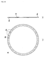
- a retainer 84 is arranged on a right end of the housing main body 46c. As shown in Fig. 6 , the retainer 84 is shaped to be fitted into an outer hull of the housing main body 46c. In the embodiment, the clutch housing 46 is cylindrical. Due to this, the retainer 85 is circular.
- the retainer 84 includes mount holes 84a and the arms 46d (see Figs. 3.and 4 ) of the housing main body 46c are fitted into the mount holes 84a.
- a stopper 84c is provided on the retainer 84 along an inner circumference of a circular portion of the retainer 84.
- the stopper 84c is shaped so that the inner circumference of the circular portion of the retainer 84 is bent in a front surface direction of Fig. 6(a) (right direction in Fig. 6(b) ).
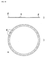
- Fig. 5(a) is a front view of a circlip 85 according to the embodiment.
- the circlip 85 has a circular shape so as to lock the retainer 84 in the housing main body 46c.
- the circlip 85 includes a slit unit 85b in a part of the circular portion.
- the retainer 84 is locked to the arms 46d by the circlip 85.
- a circlip groove 46e into which an outer circumference of the circlip 85 is fitted is provided in each arm 46d on the inner periphery of the housing main body 46c (see Fig. 4 ).
- the retainer 84 is locked to the arms 46d and supports an outer side end 83a of the disc spring 83.
- the roller retainer 78 supports the inner side end 83b of the disc spring 83 as stated above.
- a reaction force of the disc spring 83 against each roller weight 41 is always applied to the retainer 84 from left to right in Fig. 8 .
- the circlip 85 is fitted into the circlip groove 46e so as not to detach the retainer 84 from the housing main body 46c by this reaction force. Further, by fitting the circlip 85 into the circlip groove 46e, the circlip 85 restricts positions of at least the pressure plate 77 and the roller weight 41 among constituent elements of the clutch 2 in the axial direction of the main shaft 33 (see Fig. 3 ). Due to this, it is possible to ensure that the pressure plate 77 receives the centrifugal force of each roller weight 41 generated by rotation of the main shaft 33.
- the circlip 85 is suppressed from deforming radially inward by the stopper 84c provided on the retainer 84.
- a height of the stopper 84c at this time is not limited to a specific height and may be set to a height capable of suppressing radially inward deformation of the circlip 85 during actuation of the power unit 3 and preventing detachment of the circlip 85.
- the circlip 85 locks the retainer 84 and is fitted into the housing main body 46c in the following order.
- the arms 46d of the clutch housing 46 are inserted into the mount holes 84a of the retainer 84.
- the slide shaft 201 is rotated in a predetermined direction by a tool such as a driver to allow the pressure plate 77 to press the plate group 66.
- a diameter of a circle of the circlip 85 is reduced to be smaller than a diameter of a bottom of the circlip groove 46e.
- the diameter of the circle of the circlip 85 is reduced by applying a force to the circlip 85 from an outer circular arc of the circle of the circlip 85 so as to contact left and right portions of the circlip 85 separated from each other by the slit unit 85b as shown in Fig. 5 in the slit unit 85b.
- the reduced circlip 85 is fitted into the circlip groove 46e.
- Fig. 5(a) is a front view of a circlip 85 according to a first modification.
- pin stoppers 84b are provided on a circular portion of a retainer 84 according to the first modification.
- the stoppers 84b are ribs formed on a surface of the retainer 84.
- the retainer 84 is locked to the arms 46d by the circlip 85.
- the circlip 85 is suppressed from deforming radially inward by the stoppers 84b provided on the retainer 84.
- the number of the stoppers 84b and arrangement intervals thereof at this time are not limited specifically.
- a height of each of the stoppers 84b at this time is not limited to a specific height and may be set to a height capable of suppressing radially inward deformation of the circlip 85 and preventing detachment of the circlip 85 during actuation of a power unit 3.
- a manner of forming the stoppers 84b is not limited to forming of ribs on the surface of the retainer 84.
- commonly used screws are screwed into screw holes (not shown) provided in the retainer 84 and heads of the screws remaining on the surface of the retainer 84 can be used as the stoppers, respectively.
- Fig. 5(a) is a front view of a circlip 85 according to a second modification.
- the circlip 85 used in the second modification is similar to the circlip 85 used in the first modification.
- a stopper 84d is provided in one portion of a circular portion of a retainer 84.
- the stopper 84d is a rib formed on a surface of the retainer 84.
- the retainer 84 is locked to arms 46d by the circlip 85.
- the circlip 85 is suppressed from deforming radially inward by the stopper 84d provided on the retainer 84 and a housing main body 46.
- a position of the stopper 84d at this time is not limited to a specific position on the circular portion of the retainer 84.
- the position of the stopper 84d may be set to a position capable of suppressing radially inward deformation of the circlip 85 and preventing detachment of the circlip 85 during actuation of a power unit 3.
- a manner of forming the stopper 84d is not limited to forming of the rib on the surface of the retainer 84.
- a commonly used bolt is screwed into a bolt hole (not shown) provided in one portion of the circular portion of the retainer 84 and a head of the bolt remaining on the surface of the retainer 84 can be used as the stopper.
- the clutch 2 can suppress the radially inward deformation of the circlip 85 during driving of the engine 4.
- the radially inward deformation of the circlip 85 By suppressing the radially inward deformation of the circlip 85, detachment of the circlip 85 from the clutch housing 46 can be prevented.
- the clutch 2 includes the stopper suppressing the radially inward deformation of the circlip 85.
- the stopper suppressing the radially inward deformation of the circlip 85 is the stopper 84b, each of the stoppers 84c or the stopper 84d provided on the surface of the retainer 84.
- the circlip 85 is suppressed from deforming radially inward by the stopper during driving of the engine 4. It is, therefore, possible to prevent detachment of the circlip 85 from the clutch housing 46.
- each stopper 84c, and the stopper 84d is provided on the surface of the retainer 84 as a part of the retainer 84, the position of the circlip 85 in the housing main body 46c can be held and the circlip 85 can be prevented from detaching from the arms 46d without increasing the number of components related to the clutch 2.
- the clutch 2 is a centrifugal friction clutch.
- the clutch 2 includes the centrifugal weights 41 and the roller retainer 78.
- Each of the centrifugal weights 41 receives a centrifugal force by rotation of the main shaft 33 and moves toward the centrifugal direction from the axial center of the main shaft 33.
- Each of the cam surfaces 81 which are provided on the pressure plate 77, restricts movement of one of the centrifugal weights 41 in the centrifugal direction and converts the centrifugal force into the force in the axial direction of the main shaft 33.
- the roller retainer 78 stops movement of the centrifugal weight 41 in the axial direction and supports the inner side end 83b of the disc spring 83.
- the retainer 84 supports the outer side end 83a of the disc spring 83. By supporting the outer side end 83a of the disc spring 83, the retainer 84 receives the reaction force of the disc spring 83. Due to this, in the centrifugal friction clutch 2 according to the embodiment, the reaction force of the disc spring 83 loaded onto the retainer 84 is great, as compared with a non-centrifugal friction clutch. Moreover, the circlip 85 locks the retainer 84 by being fitted into the housing main body 46c. Therefore, the clutch 2 according to the embodiment exhibits a greater advantage of preventing the detachment of the circlip 85 than that of the non-centrifugal friction clutch.
- the clutch 2 is a multiple-disc friction clutch.
- the clutch 2 includes a plurality of friction plates 64 in the clutch housing 46 and includes a plurality of clutch plates 65 in the clutch boss 48.
- the plural friction plates 64 and the plural clutch plates 65 are alternately arranged in a predetermined direction. Further, the pressure plate 77 contacts the friction plates 64 with the clutch plates 65 by moving in the predetermined direction.
- the disc spring 83 applies a force assisting in the contact between the friction plates 64 and the clutch plates 65.
- the retainer 84 receives the reaction force of the disc spring 83 by supporting the outer side end 83a of the disc spring 83.
- the disc spring 83 needs a greater urge force than that in a friction clutch that is not the multiple-disc type by a plurality of pairs of friction plates 64 and clutch plates 65. Due to this, in the multiple-disc friction clutch according to the embodiment, the reaction force of the disc spring 83 loaded onto the retainer 84 is greater than that in the friction clutch that is not the multiple-disc type. Further, the circlip 85 locks the retainer 84 by being fitted into the housing main body 46c. Therefore, the clutch 2 according to the embodiment exhibits a greater advantage of preventing detachment of the circlip 85 than that of the friction clutch that is not the multiple-disc type.
- the clutch 2 according to the embodiment includes the toggle mechanism 200.
- the toggle mechanism 200 By including the toggle mechanism 200 in a large-capacity clutch such as the clutch 2, it is possible to facilitate disengaging the clutch 2 by the clutch lever 24. Namely, as compared with a clutch that does not include the toggle mechanism 200, a force required to disengage the clutch can be reduced.
- the toggle mechanism 200 is provided in the clutch so as to reduce the force required to manipulate the large-capacity clutch.
- the diameter of each of the plates, for example, the friction plates 64 and the clutch plates 65 related to disengagement of the clutch 2 is larger than that of each of plates in a small-capacity clutch.
- the diameter of the clutch housing 46 covering up the friction plates 64 and the clutch plates 65 is larger than that in the small-capacity clutch.
- the disc spring 83 applies the force assisting in the contact between the friction plates 64 and the clutch plates 65. Due to this, the disc spring 83 needs a greater urge force than that in the small-capacity clutch.
- the retainer 84 receives the reaction force of the disc spring 83 by supporting the outer side end 83a of the disc spring 83.
- the circlip 85 locks the retainer 84 by being fitted into the arms 46d of the housing main body 46c. In the large-diameter clutch, the diameter of the circle of the circlip 85 is large as compared with the small-diameter clutch.
- the clutch 2 Due to this, during actuation of the power unit 3, a greater centrifugal force is generated on the entire circlip 85 than that in the small-capacity clutch. If a relatively great centrifugal force is generated on the entire circlip 85, a greater frictional force is generated between the outer circumferential side of the circle of the circlip 85 and the inner hull of the housing main body 46c. If such a relatively great frictional force is dropped instantaneously, the probability of deforming the circular portion of the circlip 85 increases. If the circlip 85 deforms, the circlip 85 may possibly detach from the housing main body 45c. Therefore, the clutch 2 according to the embodiment exhibits the greater advantage of preventing the detachment of the circlip 85 than that of the small-capacity clutch 2.
- the clutch 2 according to the embodiment can be used in a vehicle.
- the vehicle including the clutch 2 can run stably in various running conditions because the detachment of the circlip 85 is prevented.
- the clutch 2 according to the embodiment can be used in a motorcycle.
- the motorcycle often requires complicated throttle operation as compared with the other types of vehicles.
- the engine 4 is driven at higher engine speed than that of the engine of the other types of vehicles. Due to this, the main shaft 33 of the clutch 2 is driven at a higher rotational speed.
- a greater centrifugal force is generated on the circlip 85 fitted into the clutch housing 46 by driving at the higher engine speed. If a relatively great centrifugal force is generated on the entire circlip 85, a greater frictional force is generated between the outer circumferential side of the circle of the circlip 85 and the inner hull of the housing main body 46c.
- the clutch 2 exhibits the greater advantage of preventing the detachment of the circlip 85 by being included in the motorcycle 1.
- the stopper is provided on the retainer 84 as means for suppressing the radially inward deformation of the circlip 85.
- the means for suppressing the radially inward deformation of the circlip 85 is not necessarily limited to a structure provided on the retainer 84.
- the circlip 85 may be structured per se to suppress the radially inward deformation of the circlip 85.
- a circlip 85 is circular so as to lock a retainer 84 to a housing main body 46c.
- a slit 85a is provided in one certain portion on a circular portion of the circlip 85.
- a shape and an angle of the slit 85a are not limited specifically as long as the circular portion of the circlip 85 is broken in one portion.
- the slit 85a is formed at right angle toward a center of a circle from one portion on an outer circular arc of the circle.
- a width W of the slit 85a shown in Fig. 16 is smaller than a difference in radius between an outer circle and an inner circle of the circlip 85. In other words, the width W satisfies T ⁇ (D1-D2)/2 while a diameter of the outer circle of the circlip 85 is assumed as D1 and that of the inner circle thereof is assumed as D2.
- the retainer 84 has such a shape as to be fitted into an outer hull of the housing main body 46c.
- a clutch housing 46 has a cylindrical shape. Due to this, the retainer 84 has a circular shape.
- Mount holes 84a are formed in the retainer 84 and arms 46d (see Figs. 3 and 4 ) of the housing main body 46c are fitted into the mount holes 84a.
- the retainer 84 is locked to the arm 46d by the circlip 85.
- a circlip groove 46e into which an outer circumference of the circlip 85 is fitted is provided in each of the arms 46d on an inner periphery of the housing main body 46c (see Fig. 4 ).
- the retainer 84 is locked to the arms 46d and supports an outer side end 83a of a disc spring 83.
- a roller retainer 78 supports an inner side end of the disc spring 83 as stated above.
- a reaction force of the disc spring 83 against each roller weight 41 is always applied to the retainer 84 from left to right in Fig. 8 .
- the circlip 85 is fitted into the circlip groove 46e so as not to detach the retainer 84 from the housing main body 46c by this reaction force. Further, by fitting the circlip 85 into the circlip groove 46e, the circlip 85 restricts positions of at least a pressure plate 77 and the roller weight 41 among constituent elements of the clutch 2 in an axial direction of a main shaft 33 (see Fig. 3 ). Due to this, it is possible to ensure that the pressure plate 77 receives a centrifugal force of each roller weight 41 generated by rotation of the main shaft 33.
- the circlip 85 locks the retainer 84 and is fitted into the housing main body 46c in the following order.
- the arms 46d of the clutch housing 46 are inserted into the mount holes 84a of the retainer 84.
- a slide shaft 201 is rotated in a predetermined direction by a tool such as a driver to allow the pressure plate 77 to press the plate group 66.
- a diameter of the circle of the circlip 85 is reduced to be smaller than a diameter of a bottom of the circlip groove 46e.
- the diameter of the circle of the circlip 85 is reduced by applying a force to the circlip 85 from an outer circular arc of the circle of the circlip 85 so as to cross left and right portions of the circlip 85 separated by the slit 85a as shown in Fig. 16 with each other from the slit 85a.
- the reduced circlip 85 is fitted into the circlip groove 46e.
- the crossing portions overlap each other on front and rear surfaces of a sheet of Fig. 16 (crosswise in Figs.
- a portion in which the left and right of the circlip 85 overlap each other has a thickness twice or more as large as that of other portions of the circlip 85. Due to this, one of the circlip grooves 46e has a width twice or more as large as that of the other circlip grooves 46e in one of the portions and regions of a plurality of arms 46d so that the portion in which the left and right of the circlip 85 overlap each other can be fitted into the housing main body 46c.
- the portion and region in which the twice or more width is set are not limited to a specific one of the arms 46d as long as the circlip 85 does not detach during actuation of a power unit 3.
- the left and right portions of the circlip 85 can contact each other in a cross section of the slit 85a by the slit 85a. Namely, even if the diameter of the circle of the circlip 85 is to be reduced, the diameter is hardly reduced during actuation of the power unit 3 since both side portions of the circlip 85 across the slit 85a abut on each other. Therefore, it is possible to prevent detachment of the circlip 85 from the arms 46d by providing the slit 85a in the circlip 85.
- the clutch 2 according to the second embodiment is configured to suppress the radially inward deformation of the circlip 85.
- Examples of a configuration for suppressing the radially inward deformation of the circlip 85 include the slit 85a formed by working the circlip 85.
- the left and right portions of the circlip 85 can contact each other in the cross section of the slit 85a even if the diameter of the circle of the circlip 85 is to be reduced while an engine 4 is being driven. Namely, even if the diameter of the circle of the circlip 85 is to be reduced, both side portions of the slit 85a abut on each other. Due to this, the diameter of the circle of the circlip 85 is hardly reduced during actuation of the power unit 3. It is, therefore, possible to prevent detachment of the circlip 85 from the clutch housing 46.
- the present invention is effective for a friction clutch.
Abstract
Description
- The present invention relates to a friction clutch.
- There is conventionally known a friction clutch structured to restrict positions of constituent elements of the friction clutch such as plates and a clutch spring related to rotation of a clutch shaft in an axial direction of the clutch shaft. The friction clutch having such a structure is, for example, a friction clutch described in Japanese Patent Application Laid-Open No.
2003-322177 - The friction clutch described in
JP2003-322177 - Moreover, the multiple-disc automatic centrifugal friction clutch includes a clutch plate spring (=clutch spring) generating the pressing force of the pressure plate. Namely, the clutch plate spring presses the drive plate and the driven plate. Further, the pressurization on the drive plate and the driven plate should hold the drive plate and the driven plate at predetermined positions at predetermined intervals. Due to this, the multiple-disc automatic centrifugal friction clutch includes a circlip (retaining ring) for restricting positions of constituent elements of a clutch housing such as the pressure plate, the drive plate, the driven plate, the centrifugal weight, and the clutch plate spring in the axial direction of the clutch shaft. This circlip is fitted into the clutch housing covering up the drive plate and the driven plate included in the clutch. A position at which the circlip is fitted into the clutch housing is one end side of the clutch housing in the axial direction of the clutch shaft. The circlip restricts positions of the constituent elements of the clutch housing such as the plate, the centrifugal weight, and the clutch plate spring related to rotation of the clutch shaft in the axial direction of the clutch shaft by being fitted into the clutch housing. Further, the circlip receives a reaction force to an urge force of the clutch plate spring and prevents detachment of such plates as the drive plate and the driven plate from the clutch housing by being fitted into the clutch housing.
- However, if power of the engine is improved in a motorcycle or the like, it is necessary to ensure transmitting the drive force of the high-power engine. Due to this, the clutch serving as a transmission mechanism transmitting the drive force of the engine is configured, for example, so that diameters of the plates including the friction plate and the clutch plate are increased so as to correspond to the high-power engine. In the clutch having such larger-diameter plates, a diameter of the circlip preventing detachment of such plates as the friction plate and the clutch plate is also made larger.
- Nevertheless, the inventor of the present application has discovered from various experiments that the circlip often detaches from the clutch housing in the friction clutch including the larger-diameter circlip.
- The present invention has been made in view of known systems. It is an object of one aspect of the present invention to prevent a retaining ring (such as a circlip) from detaching from a clutch housing.
- The inventor of the present application has identified that a cause for detachment of the circlip is a radially inward deformation of the circlip.
- Namely, it is considered that a shape of the circlip and a load imposed on the circlip influence the detachment of the circlip. The circlip has a substantially circular shape and an outer circumferential side of the circlip is fitted into the clutch housing. Therefore, this follows that the deformation of the circlip tends to occur on an inner circumferential side rather than on the outer circumferential side. This deformation is considered to result from the fact that the circlip has a substantially circular shape and has a so-called C shape having a slit formed in a part of the circlip.
- The C-shaped circlip is, for example, a circlip shown in
Fig. 5 . This circlip has aslit unit 85b. When this circlip is fitted into a clutch housing, a diameter of an outer circumference side of the circlip is temporarily reduced to be smaller than an inner hull of the clutch housing. The diameter of the circlip is reduced by, for example, applying a force from an outer circular arc of this circlip so that theslit unit 85b contacts left and right portions of the circlip separated by theslit unit 85b with each other. The circlip fitted into the clutch housing generates a force extending the diameter (hereinafter, referred to as "extension force"). This extension force enables the inner hull of the clutch housing and the outer circumferential side of this circlip to contact each other. - Furthermore, similarly to the clutch described in
JP2003-322177 Fig. 5 often includes a clutch spring (clutch plate spring). In this case, similarly to the circlip described inJP2003-322177 circlip 85 is fitted into the clutch housing, thereby receiving a reaction force to the urge force of the clutch spring. The reaction force to the urge force of the clutch housing causes front and rear surfaces (front and rear surfaces on a sheet ofFig. 5(a) ) of the circlip to contact with the clutch housing. The contact of thecirclip 85 with the clutch housing allows thecirclip 85 and the clutch housing to generate a frictional force in a portion in which thecirclip 85 and the clutch housing contact each other. - Moreover, if the clutch including the
circlip 85 is a centrifugal clutch similar to the clutch described inJP2003-322177 JP2003-322177 - Further, as the clutch shaft rotates, a centrifugal force is generated at mass points on a circular portion of the circlip. This centrifugal force is greater if the rotational speed of the clutch shaft is higher. This centrifugal force and the extension force of the circlip described previously enable the circlip to contact with the inner hull of the clutch housing on the outer circumferential side of the circlip.
- As stated above, the outer circumferential side of the circlip contacts with the inner hull of clutch housing by the extension force radially outward of the circlip. Further, the circlip receives the reaction force to the urge force of the clutch spring. The front and rear surfaces (front and rear surfaces on the sheet of
Fig. 5(a) ) of the circlip contact with the clutch housing by the reaction force of the clutch housing to the urge force. Due to this, the frictional force is generated in the portion in which the circlip contacts with the clutch housing. However, the frictional force applied to the portion in which the circlip contacts with the clutch housing is not uniform on the entire circlip. Namely, the frictional force of the friction with the clutch housing differs in magnitude or the like among the mass points on the circlip. This results from the fact that a shape of the outer circumferential side of the circlip does not completely coincide with that of the inner hull of the clutch housing. Furthermore, surfaces of the circlip and the clutch housing are not completely flat physically, so that portions in which the clutch housing contacts with the circlip with very small space therebetween are present. Besides, during driving of the engine related to actuation of the clutch, the frictional force is considered to change at the respective mass points on the circlip. - If the frictional force changes at the respective mass points on the circlip, the circlip is considered to deform. However, the outer circumferential side of the circlip can contact with the inner hull of the clutch housing. Due to this, it is considered that the inner circumferential side of the circlip deforms more easily than the outer circumferential side thereof.
- From these viewpoints, the inventor of the present application has conducted studies about the radially inward deformation of the circlip and finally attained the following invention.
- A friction clutch according to the present invention p:
- a main shaft driven to rotate by the engine; a clutch housing including a first plate, and rotating along the main shaft; a clutch boss including a second plate opposed to the first plate in a predetermined direction; a pressure plate, and causing the first plate and the second plate to contact each other by moving in the predetermined direction; a clutch spring arranged on an opposite side of the pressure plate to the first and second plates in the predetermined direction, and applying a force in a direction of causing the first plate and the second plate to contact each other to the pressure plate; a retainer formed into a substantially circular shape, and receiving a reaction force of the clutch spring by supporting one end of the clutch spring opposite to the pressure plate; and a retaining ring having a substantially circular shape, having a slit extending in a radial direction and formed in a circumferential part of the retaining ring, fitted into an inner peripheral side of the clutch housing, and locking the retainer to the clutch housing by abutting on an opposite side of the retainer to the clutch spring, and the friction clutch is configured to suppress the circlip from deforming radially inward.
- As stated above, according to the present invention, it is possible to prevent detachment of the retaining ring (circlip or the like) from the clutch housing.
- Embodiments of the invention will be described hereinafter, by way of example only, with reference to the accompanying drawings in which:
-
Fig. 1 is a side view of a motorcycle; -
Fig. 2 is a configuration diagram of principal elements of a power unit; -
Fig. 3 is a cross-sectional view of a clutch; -
Fig. 4 is a perspective view showing a clutch housing seen from obliquely upward; -
Figs. 5(a) and 5(b) show a circlip according to a first embodiment, whereinFig. 5 (a) is a front view andFig. 5(b) is a cross-sectional view; -
Figs. 6 (a) and 6 (b) show a retainer according to the first embodiment, whereinFig. 6 (a) is a front view andFig. 6 (b) is a cross-sectional view; -
Fig. 7 is a front view showing a state in which the retainer and the circlip are attached to a clutch housing according to the first embodiment; -
Fig. 8 is an enlarged cross-sectional view of a clutch according to the first embodiment; -
Figs. 9(a) and 9(b) show a retainer according to a first modification, whereinFig. 9(a) is a front view andFig. 9(b) is a cross-sectional view; -
Fig. 10 is a front view showing a state in which the retainer and a circlip are attached to a clutch housing according to the first modification; -
Fig. 11 is an enlarged cross-sectional view of a clutch according to the first modification; -
Figs. 12 (a) and 12 (b) show a retainer according to a second modification, whereinFig. 12 (a) is a front view andFig. 12 (b) is a cross-sectional view; -
Fig. 13 is a front view showing a state in which the retainer and a circlip are attached to a clutch housing according to the second modification; -
Fig. 14 is an enlarged cross-sectional view of a clutch according to the second modification; -
Figs. 15 (a) and 15 (b) show a retainer according to a second embodiment, whereinFig. 15 (a) is a front view andFig. 15(b) is a cross-sectional view; -
Figs. 16(a) and 16(b) show a circlip according to the second embodiment, whereinFig. 16 (a) is a front view andFig. 16(b) is a cross-sectional view; -
Fig. 17 is a front view showing a state in which the retainer and the circlip are attached to a clutch housing according to the second embodiment; and -
Fig. 18 is an enlarged cross-sectional view of a clutch according to the second embodiment. - While the invention is susceptible to various modifications and alternative forms, specific embodiments are shown by way of example in the drawings and are herein described in detail. It should be understood, however, that drawings and detailed description thereto are not intended to limit the invention to the particular form disclosed, but on the contrary, the invention is to cover all modifications, equivalents and alternatives falling within the spirit and scope of the present invention as defined by the appended claims.
- Prior to description of embodiments of the present invention, background of the present invention will be described first.
- As already stated, in the clutch having larger-diameter plates such as the friction plate and the clutch plate, the diameter of the circlip preventing detachment of such plates as the friction plate and the clutch plate is also made larger. Furthermore, since it is necessary to increase the pressing force of the pressure plate pressing the friction plate and the clutch plate, the urge force of the clutch spring urging this pressing force is also increased. If the urge force of the clutch spring is greater, the load imposed on the circlip receiving the reaction force to the urge force of the clutch spring becomes heavier.
- The centrifugal force is generated at the respective mass points on the circlip when the clutch shaft rotates during driving of the engine. In the high-power engine, a greater centrifugal force according to a mass of the circlip is generated in an entire larger-diameter circlip than a smaller-diameter circlip. Moreover, if the clutch shaft rotates at high rotational speed by being driven by the engine at high engine speed, a greater centrifugal force is generated than that generated when the clutch shaft rotates at low rotational speed.
- Furthermore, a length of a circular arc on the outer circumferential side of the circlip in contact with the inner hull of the clutch housing is according to the diameter of the circlip. Due to this, if the circlip has a larger diameter, a contact area between the inner hull of the clutch housing and the outer circumferential side of the circlip is larger. Therefore, the frictional force generated between the outer circumferential side of the larger-diameter circlip and the inner hull of the clutch housing is relatively great by as much as an increase in the contact area.
- The detachment of the circlip is conspicuously recognized when the drive force is instantaneously recovered from driving of the engine at high engine speed. Namely, the detachment of the circlip is a phenomenon that occurs when a throttle valve used to drive the engine is closed to a minimum opening position instantaneously from a maximum opening position. Due to this, the inventor of the present application has considered, as a cause for the detachment of the circlip, a sudden drop in the rotational speed of the clutch shaft and a sudden drop in the centrifugal force on the entire circlip, accordingly. Further, when the centrifugal force of the entire circlip suddenly drops, it is considered that the frictional force between the circlip and the clutch housing also suddenly falls. The circlip for which the frictional force between the circlip and the clutch housing falls is considered to rotate relatively to the clutch housing. The relative rotation of the circlip to the clutch housing is considered to result from sliding of the circlip having an inertial force generated by the rotation of the clutch shaft on the clutch housing having the reduced frictional force.
- As already stated, the frictional force differs among the mass points on the circlip in the magnitude or the like. Due to this, during the relative rotation of the circlip to the clutch housing, it is considered that the inertial force is greater than the frictional force at some mass points and that the frictional force is greater than the inertial force at other mass points. Therefore, the inventor of the present application has estimated that the circlip deforms according to changes in the magnitude or the like of the frictional force at the respective mass points on the circular portion of the circlip.
- In
JP2003-322177 Fig. 5 ) is popular and normally adopted. Due to this, the inventor of the present application has used a C-shaped circlip in a clutch without exception. As shown inFig. 5 , thecirclip 85 includes theslit unit 85b in one certain portion. Since the outer circumferential side of thecirclip 85 is fitted into the clutch housing, the deformation of the outer circumferential side of thecirclip 85 less occurs. However, the inner circumferential side of thecirclip 85 is considered to deform more easily than the outer circumferential side thereof. - If the inner circumferential side of the
circlip 85 deforms radially inward, thecirclip 85 often temporarily detaches from the portion (clutch housing) held in the clutch instantaneously. Even if a detached portion is only a part of thecirclip 85, thecirclip 85 instantaneously detaches from the clutch housing by the great urge force of the clutch spring. - Therefore, an interior of the clutch is configured to suppress the radially inward deformation of the circlip so as to be able to prevent the detachment of the circlip from the clutch housing.
- A vehicle including a centrifugal clutch according to embodiments of the present invention will be described hereinafter in detail with reference to the drawings. It is to be noted, however, that the vehicle described below is only an example of a preferred mode for carrying out the present invention. The vehicle according to the present invention is not limited to a motorcycle 1. In the present specification, the motorcycle is a vehicle of a type in which the vehicle body is leaned at the time of a turn. The motorcycle mentioned herein is not limited to a two-wheeled vehicle but may be a vehicle having three or more wheels.
-
Fig. 1 is a left side view of the motorcycle 1 according to an embodiment. In the following description, it is assumed that longitudinal and crosswise directions are directions viewed from a passenger seated on aseat 16 to be described later. - As shown in
Fig. 1 , the motorcycle 1 includes a vehicle main body 7, afront wheel 14 provided in front of the vehicle main body 7, and arear wheel 19 provided in rear of the vehicle main body 7. - The vehicle main body 7 includes a
body frame 10. Thebody frame 10 includes ahead pipe 11. Ahandle 12 is attached to an upper end of thehead pipe 11. Thefront wheel 14 is rotatably attached to a lower end of thehead pipe 11 via afront fork 13. - A
power unit 3 is suspended on thebody frame 10. Avehicle cover 15 is attached to thebody frame 10. Theseat 16 is arranged from a substantially central portion of the vehicle main body 7 to a rear side thereof in the longitudinal direction. Afuel tank 17 is arranged in front of theseat 16. - A
rear arm 18 is pivotally supported on thebody frame 10. Therear wheel 19 serving as a driving wheel is rotatably attached to a rear end of therear arm 18. Therear wheel 19 is coupled to an engine 4 (seeFig. 2 ) via a power transmission mechanism that is not shown. Power of theengine 4 is thereby transmitted to therear wheel 19 to rotate therear wheel 19. - An accelerator grip, not shown, serving as an accelerator manipulating element is provided on the right of the
handle 12. Aleft grip 29 is provided on the left of thehandle 12. Further, a clutch lever 24 serving as a clutch manipulating element operated if a clutch 2 (seeFig. 2 ), to be described later, is to be disengaged is provided on the left of thehandle 12 in front of theleft grip 29. - A
footrest 20L is provided in a central portion of each of left and right sides of the vehicle main body 7 in the longitudinal direction. Ashift pedal 27 operated if a transmission gear ratio of a transmission 5 (seeFig. 2 ), to be described later, is to be changed is provided on the left of the vehicle main body 7 and slightly forward of theleft footrest 20L. A side stand 28 is provided on the left of the vehicle main boy 7 and below theshift pedal 27 and thefootrest 20L. - Referring to
Fig. 2 , a configuration of principal elements of thepower unit 3 will next be described. As shown inFig. 2 , thepower unit 3 includes theengine 4, thetransmission 5, and theclutch 2. Although the type of theengine 4 is not limited to a specific type, theengine 4 is a water-cooled, four-stroke cycle, transverse four-cylinder engine according to the embodiment. - Although not shown, the
engine 4 includes four cylinders, pistons reciprocating in the cylinders, respectively, and acrankshaft 32 connected to the pistons via a connecting rod. Thecrankshaft 32 extends in a vehicle width direction.Reference numeral 31 denotes a crankcase. - As shown in
Fig. 2 , thecrankshaft 32 is connected to thetransmission 5 via theclutch 2. Thetransmission 5 includes amain shaft 33, adrive shaft 23, and agear selection mechanism 36. Themain shaft 33 is connected to thecrankshaft 32 via theclutch 2. Themain shaft 33 and thedrive shaft 23 are arranged in parallel to thecrankshaft 32, respectively. - Multiple transmission gears 34 are attached to the
main shaft 33. A plurality of transmission gears 35 corresponding to the multiple transmission gears 34 is attached to thedrive shaft 23. The plural transmission gears 34 and the plural transmission gears 35 are engaged with one another only based on a one-to-one correspondence. At least either the transmission gears 34 other than the selectedtransmission gear 34 among the plural transmission gears 34 or the transmission gears 35 other than the selected transmission gear 35 among the plural transmission gears 35 are rotatable about themain shaft 33 or thedrain shaft 23. Namely, at least either the unselected transmission gears 34 or the unselected transmission gears 35 run idle about themain shaft 33 or thedrive shaft 23. In other words, rotation is transmitted between themain shaft 33 and thedrive shaft 23 only via the selectedtransmission gear 34 and the selected transmission gear 35 engaged with each other. - The
gear selection mechanism 36 selects the transmission gears 34 and 35. Specifically, ashift cam 37 of thegear selection mechanism 36 selects the transmission gears 34 and 35. A plurality ofcam grooves 37a is formed on an outer peripheral surface of theshift cam 37. Ashift fork 38 is attached to each of thecam grooves 37a. Theshift fork 38 is engaged with predetermined transmission gears 34 and 35 of themain shaft 33 and thedrive shaft 23, respectively. By rotation of theshift cam 37, a plurality ofshift forks 38 is guided by thecam grooves 37a and moved in an axial direction of themain shaft 33. The transmission gears 34 and 35 engaged with each other are thereby selected. Specifically, only paired gears according to a rotational angle of theshift cam 37 among the plural transmission gears 34 and 35 are fixed to themain shaft 33 and thedrive shaft 23 by a spline. Positions of the transmission gears are thereby decided and the rotation is transmitted between themain shaft 33 and thedrive shaft 23 at a predetermined gear ratio via the transmission gears 34 and 35. It is to be noted that thisgear selection mechanism 36 is operated by theshift pedal 27 shown inFig. 1 . - With such a configuration, if predetermined paired transmission gears 34 and 35 are fixed to the
main shaft 33 and thedrive shaft 23, theclutch 2 is engaged and theengine 4 is driven, the power of theengine 4 is transmitted to themain shaft 33 via theclutch 2. Furthermore, rotation is transmitted between themain shaft 33 and thedrive shaft 23 at the predetermined transmission gear ratio via the predetermined paired transmission gears 34 and 35, thereby driving thedrive shaft 23 to rotate. If thedrive shaft 23 is driven to rotate, a transmission mechanism (not shown) such as a chain connecting thedrive shaft 23 to therear wheel 19 transmits a drive force to therear wheel 19, thereby rotating therear wheel 19. In the embodiment, the power transmission mechanism connecting theengine 4 to therear wheel 19 is constituted by theclutch 2, thetransmission 5, and the transmission mechanism (not shown) such as a chain. - In the embodiment, the
clutch 2 is constituted by a multiple-disc friction clutch. Further, theclutch 2 is a centrifugal clutch automatically disengaged at the time of takeoff and standstill and disengaged by rider's operating the clutch lever 24. A configuration of the clutch 2 will be described in detail. - As shown in
Fig. 3 , theclutch 2 includes aclutch housing 46. Themain shaft 33 penetrates through theclutch housing 46. Theclutch housing 46 includes a housingmain body 46c. The housingmain body 46c is formed into a substantially cylindrical shape having one end closed by a bottom 46a. Themain shaft 33 is inserted into the bottom 46a of the housingmain body 46c. The housingmain body 46c includes a plurality of pairs ofarms 46d. Each of thearms 46d extends from the bottom 46a toward outside of the vehicle width direction. Further, acirclip groove 46e is provided in eacharm 46d on the inner periphery of thearm 46d as described later. - As shown in
Fig. 3 , the vehicle width direction is the crosswise direction. In the embodiment, since theclutch 2 is arranged on the right side of themain shaft 33, the outside' of the vehicle width direction corresponds to the right side and the inside thereof corresponds to the left side. Therefore, the outside and inside of the vehicle width direction will be simply referred to as "right side and left side", respectively. - A
scissors gear 45 is attached to theclutch housing 46. The scissors gear 45 includes twogears spring 49, and twoplates gears plates plates main shaft 33. The twogears main shaft 33. With respect to the rotational direction, the twogears - The
gears gears spring 49 is provided between thegears gears spring 49. The torsion torque absorbs fluctuation torque of theengine 4. - The
gear 45a of thescissors gear 45 is engaged with agear 32a (seeFig. 2 ) of thecrankshaft 2. Thegear 45a of thescissors gear 45 is fixed to the bottom 46a of theclutch housing 46 so as not to be able to relatively rotate. With such a configuration, thegear 45a of thescissors gear 45 and theclutch housing 46 integrally rotate to follow rotation of thecrankshaft 32. - A
needle bearing 53 and aspacer 54 that is nonrotatably fixed to themain shaft 33 are arranged between thescissors gear 45 and themain shaft 33. The scissors gear 45 is rotatable about themain shaft 33 by thisneedle bearing 53. Namely, rotation of thescissors gear 45 is intended not to be directly transmitted to themain shaft 33. - A
clutch boss 48 is nonrotatably fixed to themain shaft 33 by anut 67. Namely, theclutch boss 48 rotates along with the main shaft 44. A thrust bearing 63 is arranged between theclutch boss 48 and thescissors gear 45. Thescissors gear 45, theneedle bearing 53, thespacer 54, and theclutch boss 48 are restricted by the thrust bearing 63 so as not to be close to one another at a predetermined distance or less. Namely, thescissors gear 45, theneedle bearing 53, and thespacer 54 are restricted to move to theclutch boss 48 with respect to the axial direction of themain shaft 33. - A plurality of
friction plates 64 is arranged inside of theclutch housing 46. Eachfriction plate 64 is fixed to theclutch housing 46 with respect to the rotational direction of themain shaft 33. Due to this, theplural friction plates 64 rotate along with theclutch housing 46. Eachfriction plate 64 is displaceable with respect to the axial direction of themain shaft 33. Due to this, a distance between the twoadjacent friction plates 64 is variable. - The
plural friction plates 64 are arranged in the axial direction of themain shaft 33. Aclutch plate 65 is arranged between the twoadjacent friction plates 64. Theclutch plate 65 is opposed to theadjacent friction plate 64. Eachclutch plate 65 is fixed to theclutch boss 48 with respect to the rotational direction of themain shaft 33. Due to this, the pluralclutch plates 65 rotate along with theclutch boss 48. Eachclutch plate 65 is displaceable with respect to the axial direction of themain shaft 33. Due to this, a distance between the two adjacentclutch plates 65 is variable. - In the embodiment, a
plate group 66 is constituted by theseplural friction plates 64 and the pluralclutch plates 65. - A
pressure plate 77 is arranged on the right of themain shaft 33. Thepressure plate 77 is formed into a substantially disc shape. A sub-clutch 100, to be described later, is provided in a center-side portion of thepressure plate 77. A radially outward end of thepressure plate 77 is engaged witharms 46d. Thepressure plate 77 is thereby nonrotatable about theclutch housing 46 and rotates along with theclutch housing 46. - A
pressing portion 77b protruding toward theplate group 66 is formed in a radially outward portion of thepressure plate 77. Thispressing portion 77b is opposed to thefriction plate 64 located on a rightmost side of theplate group 66. If thepressure plate 77 moves left, thispressing portion 77b presses theplate group 66 leftward. As a result, thefriction plates 64 and theclutch plates 65 of theplate group 66 are press-contacted. - Meanwhile, a
cam surface 81 supporting aroller weight 41 is formed on an opposite surface to theplate group 66 in the radially outward portion of thepressure plate 77. A plurality of cam surfaces 81 and a plurality ofroller weights 41 are provided along the circumferential direction. The plural cam surfaces 81 are arranged radially about an axial center of themain shaft 33. The cam surfaces 81 are inclined so as to be directed to righter side on outer side of the radial direction. - A
roller retainer 78 is arranged on the right of thepressure plate 77. Theroller retainer 78 is formed into an orbicular zone shape viewed from the axial direction of themain shaft 33. Theroller retainer 78 is opposed to the cam surfaces 81 of thepressure plate 77. Aspace 82 narrower toward outward of the radial direction of themain shaft 33 is thereby formed by eachcam surface 81 and theroller retainer 78. - Similarly to the
pressure plate 77, a radially outward end of theroller retainer 78 is engaged with theplural arms 46d. Theroller retainer 78 is thereby nonrotatable about theclutch housing 46. In other words, theroller retainer 78 rotates along with theclutch housing 46. In the axial direction of themain shaft 33, theroller retainer 78 is displaceable with respect to theclutch housing 46. - The
roller retainer 78 supports aninner side end 83b of a disc spring. Due to this, theroller retainer 78 is urged leftward by adisc spring 83. In other words, theroller retainer 78 is urged toward theplate group 66 by thedisc spring 83. Theroller retainer 78 and thedisc spring 83 constitute anabutment member 70 abutting oneroller weight 41 on one of the cam surfaces 81. - The
roller weights 41 are arranged in a plurality ofspaces 82, respectively. Eachroller weight 41 revolves to follow rotation of theclutch housing 46 and moves on onecam surface 81 toward radially outward by a centrifugal force generated during the revolution. Theroller weight 41 receives a reaction force from theabutment member 70 and presses thepressure plate 77 toward theplate group 66. - If a rotational speed of the
crankshaft 32 is low, a rotational speed of theclutch housing 46 becomes low accordingly. Due to this, the centrifugal force acting on eachroller weight 41 is relatively low and theroller weight 41 is located relatively inward. A force by which theroller weight 41 presses thepressure plate 77 leftward thereby weakens. As a result, the degree of pressure-contact of theplate group 66 weakens and torque transmittable from theclutch housing 46 to theclutch boss 48 becomes relatively low. - On the other hand, if the rotational speed of the
crankshaft 32 is relatively high, the rotational speed of theclutch housing 46 becomes relatively high accordingly. Due to this, as the rotational speed of theclutch housing 46 is larger, the centrifugal force acting on eachroller weight 41 becomes stronger. If the centrifugal force acting on theroller weight 41 is equal to or greater than a predetermined value, theroller weight 41 moves outward. Thepressure plate 77 is thereby pressed leftward by theroller weight 41 and moved toward theplate group 66. As a result, theplate group 66 is pressure-contacted relatively strongly and the torque transmittable from theclutch housing 46 to theclutch boss 48 becomes relatively high. - As shown in
Fig. 3 , the clutch 2 according to the embodiment includes asub clutch 100. Thesub clutch 100 includes afriction plate 101, a firstpressing plate 102 opposed to a left surface (hereinafter, "first friction surface") 101a of thefriction plate 101, and a secondpressing plate 102 opposed to a right surface (hereinafter, "second friction surface") 101b of thefriction plate 101. - The clutch 2 according to the embodiment includes a
clutch release mechanism 86. Theclutch release mechanism 86 forcibly releases a pressure-contact state of theplate group 66 in response to rider's operation of the clutch lever 24. Thisclutch release mechanism 86 enables the clutch 2 to be disengaged by a manual operation of the rider of the motorcycle 1. - As shown in
Fig. 3 , the clutch 2 according to the embodiment includes atoggle mechanism 200. Thetoggle mechanism 200 converts a part of the torque of thepressure plate 77 into a force disengaging the clutch 2 so as to reduce a force required to disengage theclutch 2. Thetoggle mechanism 200 according to the embodiment is constituted by a so-called ball cam. Thetoggle mechanism 200 includes aslide shaft 201 fixed to the secondpressing plate 103, afirst cam plate 202, asecond cam plate 203, aball plate 204, and acoil spring 205 urging thesecond cam plate 203 in a direction in which thesecond cam plate 203 separates from thefirst cam plate 202. Asupport plate 250 supporting thecoil spring 205 by abutting on a right portion of thecoil spring 205 is fixed onto a tip end side of theslide shaft 201. It is to be noted that thetoggle mechanism 200 is not limited to the ball cam structure and may be any structure as long as the mechanism is configured to reduce the force required to disengage theclutch 2. - A
retainer 84 is arranged on a right end of the housingmain body 46c. As shown inFig. 6 , theretainer 84 is shaped to be fitted into an outer hull of the housingmain body 46c. In the embodiment, theclutch housing 46 is cylindrical. Due to this, theretainer 85 is circular. Theretainer 84 includesmount holes 84a and thearms 46d (seeFigs. 3.and 4 ) of the housingmain body 46c are fitted into themount holes 84a. - A
stopper 84c is provided on theretainer 84 along an inner circumference of a circular portion of theretainer 84. Thestopper 84c is shaped so that the inner circumference of the circular portion of theretainer 84 is bent in a front surface direction ofFig. 6(a) (right direction inFig. 6(b) ). -
Fig. 5(a) is a front view of acirclip 85 according to the embodiment. Thecirclip 85 has a circular shape so as to lock theretainer 84 in the housingmain body 46c. Thecirclip 85 includes aslit unit 85b in a part of the circular portion. - As shown in
Figs. 7 and8 , theretainer 84 is locked to thearms 46d by thecirclip 85. Acirclip groove 46e into which an outer circumference of thecirclip 85 is fitted is provided in eacharm 46d on the inner periphery of the housingmain body 46c (seeFig. 4 ). Theretainer 84 is locked to thearms 46d and supports anouter side end 83a of thedisc spring 83. Theroller retainer 78 supports theinner side end 83b of thedisc spring 83 as stated above. A reaction force of thedisc spring 83 against eachroller weight 41 is always applied to theretainer 84 from left to right inFig. 8 . Thecirclip 85 is fitted into thecirclip groove 46e so as not to detach theretainer 84 from the housingmain body 46c by this reaction force. Further, by fitting thecirclip 85 into thecirclip groove 46e, thecirclip 85 restricts positions of at least thepressure plate 77 and theroller weight 41 among constituent elements of the clutch 2 in the axial direction of the main shaft 33 (seeFig. 3 ). Due to this, it is possible to ensure that thepressure plate 77 receives the centrifugal force of eachroller weight 41 generated by rotation of themain shaft 33. - Moreover, as shown in
Figs. 7 and8 , thecirclip 85 is suppressed from deforming radially inward by thestopper 84c provided on theretainer 84. A height of thestopper 84c at this time (in the crosswise direction inFig. 6(b) ) is not limited to a specific height and may be set to a height capable of suppressing radially inward deformation of thecirclip 85 during actuation of thepower unit 3 and preventing detachment of thecirclip 85. - By way of example, the
circlip 85 locks theretainer 84 and is fitted into the housingmain body 46c in the following order. In the clutch 2 shown inFig. 3 , in a state in which a region surrounded by theclutch housing 46 is incorporated (a state in which theclutch cover 31 is detached and in which thetoggle mechanism 200 is not mounted inFig. 3 ), thearms 46d of theclutch housing 46 are inserted into the mount holes 84a of theretainer 84. After inserting theretainer 84 into thearms 46d, theslide shaft 201 is rotated in a predetermined direction by a tool such as a driver to allow thepressure plate 77 to press theplate group 66. By forcibly applying the pressing force against theplate group 66 to thepressure plate 77 from outside of the clutch 2, the reaction force of thedisc spring 83 against eachroller weight 41 is eliminated from theretainer 84. - After allowing the
pressure plate 77 to press theplate group 66, a diameter of a circle of thecirclip 85 is reduced to be smaller than a diameter of a bottom of thecirclip groove 46e. The diameter of the circle of thecirclip 85 is reduced by applying a force to thecirclip 85 from an outer circular arc of the circle of thecirclip 85 so as to contact left and right portions of thecirclip 85 separated from each other by theslit unit 85b as shown inFig. 5 in theslit unit 85b. The reducedcirclip 85 is fitted into thecirclip groove 46e. - An outer circumference of the
circlip 85 is fitted into thecirclip groove 46e. Further, even if the diameter of the circle is reduced during actuation of thepower unit 3, the inner circular arc of the circular portion of thecirclip 85 contacts with theslit unit 85b by thestopper 84c. Due to this, reduction in the diameter of the circle of thecirclip 85 is restricted. In other words, the diameter of the circle of thecirclip 85 is hardly reduced during actuation of thepower unit 3. It is, therefore, possible to prevent detachment of thecirclip 85 from thearms 46d by providing thestopper 84c on theretainer 84. -
Fig. 5(a) is a front view of acirclip 85 according to a first modification. Further, as shown inFig. 9 ,pin stoppers 84b are provided on a circular portion of aretainer 84 according to the first modification. Thestoppers 84b are ribs formed on a surface of theretainer 84. As shown inFigs. 10 and11 , theretainer 84 is locked to thearms 46d by thecirclip 85. Thecirclip 85 is suppressed from deforming radially inward by thestoppers 84b provided on theretainer 84. The number of thestoppers 84b and arrangement intervals thereof at this time are not limited specifically. Further, a height of each of thestoppers 84b at this time (in the crosswise direction inFig. 9(b) ) is not limited to a specific height and may be set to a height capable of suppressing radially inward deformation of thecirclip 85 and preventing detachment of thecirclip 85 during actuation of apower unit 3. - It is to be noted that a manner of forming the
stoppers 84b is not limited to forming of ribs on the surface of theretainer 84. For example, commonly used screws are screwed into screw holes (not shown) provided in theretainer 84 and heads of the screws remaining on the surface of theretainer 84 can be used as the stoppers, respectively. -
Fig. 5(a) is a front view of acirclip 85 according to a second modification. Thecirclip 85 used in the second modification is similar to thecirclip 85 used in the first modification. Further, as shown inFig. 12 , astopper 84d is provided in one portion of a circular portion of aretainer 84. Thestopper 84d is a rib formed on a surface of theretainer 84. As shown inFigs. 13 and14 , theretainer 84 is locked toarms 46d by thecirclip 85. Thecirclip 85 is suppressed from deforming radially inward by thestopper 84d provided on theretainer 84 and a housingmain body 46. A position of thestopper 84d at this time is not limited to a specific position on the circular portion of theretainer 84. The position of thestopper 84d may be set to a position capable of suppressing radially inward deformation of thecirclip 85 and preventing detachment of thecirclip 85 during actuation of apower unit 3. - It is to be noted that a manner of forming the
stopper 84d is not limited to forming of the rib on the surface of theretainer 84. For example, a commonly used bolt is screwed into a bolt hole (not shown) provided in one portion of the circular portion of theretainer 84 and a head of the bolt remaining on the surface of theretainer 84 can be used as the stopper. - As stated so far, the clutch 2 according to the embodiment can suppress the radially inward deformation of the
circlip 85 during driving of theengine 4. By suppressing the radially inward deformation of thecirclip 85, detachment of thecirclip 85 from theclutch housing 46 can be prevented. - The clutch 2 according to the embodiment includes the stopper suppressing the radially inward deformation of the
circlip 85. The stopper suppressing the radially inward deformation of thecirclip 85 is thestopper 84b, each of thestoppers 84c or thestopper 84d provided on the surface of theretainer 84. Thecirclip 85 is suppressed from deforming radially inward by the stopper during driving of theengine 4. It is, therefore, possible to prevent detachment of thecirclip 85 from theclutch housing 46. Furthermore, if one of thestopper 84b, eachstopper 84c, and thestopper 84d is provided on the surface of theretainer 84 as a part of theretainer 84, the position of thecirclip 85 in the housingmain body 46c can be held and thecirclip 85 can be prevented from detaching from thearms 46d without increasing the number of components related to theclutch 2. - The clutch 2 according to the embodiment is a centrifugal friction clutch. The
clutch 2 includes thecentrifugal weights 41 and theroller retainer 78. Each of thecentrifugal weights 41 receives a centrifugal force by rotation of themain shaft 33 and moves toward the centrifugal direction from the axial center of themain shaft 33. Each of the cam surfaces 81, which are provided on thepressure plate 77, restricts movement of one of thecentrifugal weights 41 in the centrifugal direction and converts the centrifugal force into the force in the axial direction of themain shaft 33. Theroller retainer 78 stops movement of thecentrifugal weight 41 in the axial direction and supports theinner side end 83b of thedisc spring 83. Further, theretainer 84 supports theouter side end 83a of thedisc spring 83. By supporting theouter side end 83a of thedisc spring 83, theretainer 84 receives the reaction force of thedisc spring 83. Due to this, in thecentrifugal friction clutch 2 according to the embodiment, the reaction force of thedisc spring 83 loaded onto theretainer 84 is great, as compared with a non-centrifugal friction clutch. Moreover, thecirclip 85 locks theretainer 84 by being fitted into the housingmain body 46c. Therefore, the clutch 2 according to the embodiment exhibits a greater advantage of preventing the detachment of thecirclip 85 than that of the non-centrifugal friction clutch. - The clutch 2 according to the embodiment is a multiple-disc friction clutch. The
clutch 2 includes a plurality offriction plates 64 in theclutch housing 46 and includes a plurality ofclutch plates 65 in theclutch boss 48. Theplural friction plates 64 and the pluralclutch plates 65 are alternately arranged in a predetermined direction. Further, thepressure plate 77 contacts thefriction plates 64 with theclutch plates 65 by moving in the predetermined direction. Thedisc spring 83 applies a force assisting in the contact between thefriction plates 64 and theclutch plates 65. Theretainer 84 receives the reaction force of thedisc spring 83 by supporting theouter side end 83a of thedisc spring 83. Thedisc spring 83 needs a greater urge force than that in a friction clutch that is not the multiple-disc type by a plurality of pairs offriction plates 64 andclutch plates 65. Due to this, in the multiple-disc friction clutch according to the embodiment, the reaction force of thedisc spring 83 loaded onto theretainer 84 is greater than that in the friction clutch that is not the multiple-disc type. Further, thecirclip 85 locks theretainer 84 by being fitted into the housingmain body 46c. Therefore, the clutch 2 according to the embodiment exhibits a greater advantage of preventing detachment of thecirclip 85 than that of the friction clutch that is not the multiple-disc type. - The clutch 2 according to the embodiment includes the
toggle mechanism 200. By including thetoggle mechanism 200 in a large-capacity clutch such as theclutch 2, it is possible to facilitate disengaging the clutch 2 by the clutch lever 24. Namely, as compared with a clutch that does not include thetoggle mechanism 200, a force required to disengage the clutch can be reduced. In other words, thetoggle mechanism 200 is provided in the clutch so as to reduce the force required to manipulate the large-capacity clutch. In the clutch 2 according to the embodiment, the diameter of each of the plates, for example, thefriction plates 64 and theclutch plates 65 related to disengagement of the clutch 2 is larger than that of each of plates in a small-capacity clutch. Accordingly, the diameter of theclutch housing 46 covering up thefriction plates 64 and theclutch plates 65 is larger than that in the small-capacity clutch. Moreover, thedisc spring 83 applies the force assisting in the contact between thefriction plates 64 and theclutch plates 65. Due to this, thedisc spring 83 needs a greater urge force than that in the small-capacity clutch. Theretainer 84 receives the reaction force of thedisc spring 83 by supporting theouter side end 83a of thedisc spring 83. Thecirclip 85 locks theretainer 84 by being fitted into thearms 46d of the housingmain body 46c. In the large-diameter clutch, the diameter of the circle of thecirclip 85 is large as compared with the small-diameter clutch. Due to this, during actuation of thepower unit 3, a greater centrifugal force is generated on theentire circlip 85 than that in the small-capacity clutch. If a relatively great centrifugal force is generated on theentire circlip 85, a greater frictional force is generated between the outer circumferential side of the circle of thecirclip 85 and the inner hull of the housingmain body 46c. If such a relatively great frictional force is dropped instantaneously, the probability of deforming the circular portion of thecirclip 85 increases. If thecirclip 85 deforms, thecirclip 85 may possibly detach from the housing main body 45c. Therefore, the clutch 2 according to the embodiment exhibits the greater advantage of preventing the detachment of thecirclip 85 than that of the small-capacity clutch 2. - The clutch 2 according to the embodiment can be used in a vehicle. The vehicle including the clutch 2 can run stably in various running conditions because the detachment of the
circlip 85 is prevented. - Moreover, the clutch 2 according to the embodiment can be used in a motorcycle. The motorcycle often requires complicated throttle operation as compared with the other types of vehicles. Further, during running, the
engine 4 is driven at higher engine speed than that of the engine of the other types of vehicles. Due to this, themain shaft 33 of the clutch 2 is driven at a higher rotational speed. A greater centrifugal force is generated on thecirclip 85 fitted into theclutch housing 46 by driving at the higher engine speed. If a relatively great centrifugal force is generated on theentire circlip 85, a greater frictional force is generated between the outer circumferential side of the circle of thecirclip 85 and the inner hull of the housingmain body 46c. If such a relatively great frictional force is dropped instantaneously, the probability of deforming the circular portion of thecirclip 85 increases. If thecirclip 85 deforms, thecirclip 85 may possibly detach from the housingmain body 46c. Therefore, the clutch 2 according to the embodiment exhibits the greater advantage of preventing the detachment of thecirclip 85 by being included in the motorcycle 1. - In the previous embodiment, the stopper is provided on the
retainer 84 as means for suppressing the radially inward deformation of thecirclip 85. However, the means for suppressing the radially inward deformation of thecirclip 85 is not necessarily limited to a structure provided on theretainer 84. For example, as shown below, thecirclip 85 may be structured per se to suppress the radially inward deformation of thecirclip 85. - As shown in
Fig. 16 , acirclip 85 is circular so as to lock aretainer 84 to a housingmain body 46c. Aslit 85a is provided in one certain portion on a circular portion of thecirclip 85. A shape and an angle of theslit 85a are not limited specifically as long as the circular portion of thecirclip 85 is broken in one portion. InFig. 16 , theslit 85a is formed at right angle toward a center of a circle from one portion on an outer circular arc of the circle. A width W of theslit 85a shown inFig. 16 is smaller than a difference in radius between an outer circle and an inner circle of thecirclip 85. In other words, the width W satisfies T < (D1-D2)/2 while a diameter of the outer circle of thecirclip 85 is assumed as D1 and that of the inner circle thereof is assumed as D2. - As shown in
Fig. 15 , theretainer 84 has such a shape as to be fitted into an outer hull of the housingmain body 46c. In this embodiment, aclutch housing 46 has a cylindrical shape. Due to this, theretainer 84 has a circular shape. Mount holes 84a are formed in theretainer 84 andarms 46d (seeFigs. 3 and4 ) of the housingmain body 46c are fitted into themount holes 84a. - As shown in
Figs. 17 and18 , theretainer 84 is locked to thearm 46d by thecirclip 85. Acirclip groove 46e into which an outer circumference of thecirclip 85 is fitted is provided in each of thearms 46d on an inner periphery of the housingmain body 46c (seeFig. 4 ). Theretainer 84 is locked to thearms 46d and supports anouter side end 83a of adisc spring 83. Aroller retainer 78 supports an inner side end of thedisc spring 83 as stated above. A reaction force of thedisc spring 83 against eachroller weight 41 is always applied to theretainer 84 from left to right inFig. 8 . Thecirclip 85 is fitted into thecirclip groove 46e so as not to detach theretainer 84 from the housingmain body 46c by this reaction force. Further, by fitting thecirclip 85 into thecirclip groove 46e, thecirclip 85 restricts positions of at least apressure plate 77 and theroller weight 41 among constituent elements of the clutch 2 in an axial direction of a main shaft 33 (seeFig. 3 ). Due to this, it is possible to ensure that thepressure plate 77 receives a centrifugal force of eachroller weight 41 generated by rotation of themain shaft 33. - By way of example, the
circlip 85 locks theretainer 84 and is fitted into the housingmain body 46c in the following order. In the clutch 2 shown inFig. 3 , in a state in which a region surrounded by theclutch housing 46 is incorporated (a state in which theclutch cover 31 is detached and in which thetoggle mechanism 200 is not mounted inFig. 3 ), thearms 46d of theclutch housing 46 are inserted into the mount holes 84a of theretainer 84. After inserting theretainer 84 into thearms 46d, aslide shaft 201 is rotated in a predetermined direction by a tool such as a driver to allow thepressure plate 77 to press theplate group 66. By forcibly applying a pressing force against theplate group 66 to thepressure plate 77 from outside of the clutch 2, the reaction force of thedisc spring 83 against eachroller weight 41 is eliminated from theretainer 84. - After allowing the
pressure plate 77 to press theplate group 66, a diameter of the circle of thecirclip 85 is reduced to be smaller than a diameter of a bottom of thecirclip groove 46e. The diameter of the circle of thecirclip 85 is reduced by applying a force to thecirclip 85 from an outer circular arc of the circle of thecirclip 85 so as to cross left and right portions of thecirclip 85 separated by theslit 85a as shown inFig. 16 with each other from theslit 85a. The reducedcirclip 85 is fitted into thecirclip groove 46e. In thecirclip 85 having the reduced diameter of the circle, the crossing portions overlap each other on front and rear surfaces of a sheet ofFig. 16 (crosswise inFigs. 3 and4 ). A portion in which the left and right of thecirclip 85 overlap each other has a thickness twice or more as large as that of other portions of thecirclip 85. Due to this, one of thecirclip grooves 46e has a width twice or more as large as that of theother circlip grooves 46e in one of the portions and regions of a plurality ofarms 46d so that the portion in which the left and right of thecirclip 85 overlap each other can be fitted into the housingmain body 46c. The portion and region in which the twice or more width is set are not limited to a specific one of thearms 46d as long as thecirclip 85 does not detach during actuation of apower unit 3. - Even if the diameter of the circle of the
circlip 85 is to be reduced during actuation of thepower unit 3, the left and right portions of thecirclip 85 can contact each other in a cross section of theslit 85a by theslit 85a. Namely, even if the diameter of the circle of thecirclip 85 is to be reduced, the diameter is hardly reduced during actuation of thepower unit 3 since both side portions of thecirclip 85 across theslit 85a abut on each other. Therefore, it is possible to prevent detachment of thecirclip 85 from thearms 46d by providing theslit 85a in thecirclip 85. - The clutch 2 according to the second embodiment is configured to suppress the radially inward deformation of the
circlip 85. Examples of a configuration for suppressing the radially inward deformation of thecirclip 85 include theslit 85a formed by working thecirclip 85. By providing theslit 85a, the left and right portions of thecirclip 85 can contact each other in the cross section of theslit 85a even if the diameter of the circle of thecirclip 85 is to be reduced while anengine 4 is being driven. Namely, even if the diameter of the circle of thecirclip 85 is to be reduced, both side portions of theslit 85a abut on each other. Due to this, the diameter of the circle of thecirclip 85 is hardly reduced during actuation of thepower unit 3. It is, therefore, possible to prevent detachment of thecirclip 85 from theclutch housing 46. - The present invention is effective for a friction clutch.
-
- 1
- Motorcycle
- 2
- Clutch (friction clutch)
- 3
- Engine
- 19
- Rear wheel (driving wheel)
- 24
- Clutch lever (clutch manipulating element)
- 33
- Main shaft
- 41
- Roller weight (centrifugal weight)
- 46
- Clutch housing
- 48
- Clutch boss
- 64
- Friction plate (first plate)
- 65
- Clutch plate (second plate)
- 66
- plate group
- 77
- Pressure plate
- 78
- Roller retainer (seat)
- 81
- Cam surface
- 83
- Disc spring (clutch spring)
- 84
- Retainer
- 84a
- Mount hole
- 84b
- Stopper
- 84c
- Stopper
- 84d
- Stopper
- 85
- Circlip (retaining ring)
- 85a
- Slit
- 85b
- Slit unit
- 100
- Sub clutch
- 200
- Toggle mechanism
Claims (11)
- A friction clutch operable to transmit a drive force of an engine, comprising:a main shaft arranged to be driven to rotate by the engine;a clutch housing including a first plate, and arranged to rotate along the main shaft;a clutch boss including a second plate opposed to the first plate in a predetermined direction;a pressure plate arranged to rotate according to the main shaft, and to cause the first plate and the second plate to contact each other by moving in the predetermined direction;a clutch spring arranged on an opposite side of the pressure plate to the first and second plates in the predetermined direction, and arranged to apply a force in a direction of causing the first plate and the second plate to contact each other to the pressure plate;a retainer formed into a substantially circular shape, and arranged to receive a reaction force of the clutch spring by supporting one end of the clutch spring opposite to the pressure plate; anda retaining ring having a substantially circular shape, having a slit extending in a radial direction and formed in a circumferential part of the retaining ring, arranged to fit into an inner peripheral side of the clutch housing, to lock the retainer to the clutch housing by abutting on an opposite side of the retainer to the clutch spring,wherein the retaining ring is configured to be suppressed from deforming radially inward.
- The friction clutch according to claim 1, comprising a stopper arranged to suppress the retaining ring from deforming radially inward.
- The friction clutch according to claim 2,
wherein the stopper is a member abutting on a radially inward side of the retaining ring. - The friction clutch according to claim 2,
wherein the stopper is a member interposing between left and right ends of the retaining ring across the slit. - The friction clutch according to claim 3 or 4,
wherein the stopper is a part of the retainer. - The friction clutch according to any preceding claim,
wherein a width of the slit is smaller than a difference between a radius of an outer circle and a radius of an inner circle of the retaining ring. - The friction clutch according to any preceding claim 1, further comprising:a centrifugal weight arranged on the opposite side of the pressure plate to the first and second plate, arranged to receive a centrifugal force by rotating around the main shaft, and to move toward a centrifugal direction; anda seat locked to the clutch housing, arranged to restrict movement of the centrifugal weight in an axial direction of the main shaft, and to support one end of the clutch spring on the pressure plate side,wherein a cam surface contacting with the centrifugal weight and arranged to convert the centrifugal force into a force in the axial direction of the main shaft is formed on the opposite side of the pressure plate to the first and second plates.
- The friction clutch according to any preceding claim, comprising a plurality of the first plates and a plurality of the second plates,
wherein the plurality of first plates and the plurality of second plates are alternately arranged along the predetermined direction. - The friction clutch according to any preceding claim, comprising a toggle mechanism arranged to receive a torque of the pressure plate and to convert the torque into a force for moving the pressure plate in a direction of separating the first plate from the second plate during a clutch disengagement by a clutch manipulating element disengaging the friction clutch.
- A vehicle comprising:the friction clutch according to any preceding claim;an engine; anda driving wheel,wherein the friction clutch disengageably transmits a drive force from the engine toward the driving wheel.
- The vehicle according to claim 10, which is a motorcycle.
Applications Claiming Priority (1)
| Application Number | Priority Date | Filing Date | Title |
|---|---|---|---|
| JP2008043510A JP2009197991A (en) | 2008-02-25 | 2008-02-25 | Friction clutch |
Publications (3)
| Publication Number | Publication Date |
|---|---|
| EP2093445A2 true EP2093445A2 (en) | 2009-08-26 |
| EP2093445A3 EP2093445A3 (en) | 2013-04-10 |
| EP2093445B1 EP2093445B1 (en) | 2014-10-29 |
Family
ID=40672544
Family Applications (1)
| Application Number | Title | Priority Date | Filing Date |
|---|---|---|---|
| EP09250432.3A Not-in-force EP2093445B1 (en) | 2008-02-25 | 2009-02-19 | Friction clutch |
Country Status (3)
| Country | Link |
|---|---|
| US (2) | US20090211864A1 (en) |
| EP (1) | EP2093445B1 (en) |
| JP (1) | JP2009197991A (en) |
Cited By (1)
| Publication number | Priority date | Publication date | Assignee | Title |
|---|---|---|---|---|
| CN103912596A (en) * | 2013-01-04 | 2014-07-09 | 通用汽车环球科技运作有限责任公司 | Clutch Backing Plate With Fluid Drain |
Families Citing this family (5)
| Publication number | Priority date | Publication date | Assignee | Title |
|---|---|---|---|---|
| JP2009197990A (en) * | 2008-02-25 | 2009-09-03 | Yamaha Motor Co Ltd | Motorcycle including centrifugal clutch |
| JP3155715U (en) * | 2008-10-10 | 2009-11-26 | ヤマハ発動機株式会社 | Friction clutch and vehicle equipped with the same |
| JP5171778B2 (en) * | 2009-09-30 | 2013-03-27 | 本田技研工業株式会社 | Multi-plate clutch device |
| DE102018110881A1 (en) * | 2018-05-07 | 2019-11-07 | Schaeffler Technologies AG & Co. KG | Arrangement for centrifugal force securing at least one on a rotor shaft of an electric machine for securing the position axially fixed securing ring and use of such an arrangement |
| WO2022176693A1 (en) * | 2021-02-18 | 2022-08-25 | ヤマハ発動機株式会社 | Centrifugal clutch and straddle-type vehicle |
Citations (1)
| Publication number | Priority date | Publication date | Assignee | Title |
|---|---|---|---|---|
| JP2003322177A (en) | 2002-04-26 | 2003-11-14 | Suzuki Motor Corp | Multiple-disc automatic centrifugal clutch device |
Family Cites Families (7)
| Publication number | Priority date | Publication date | Assignee | Title |
|---|---|---|---|---|
| US3265172A (en) * | 1963-04-26 | 1966-08-09 | Suzuki Motor Co | Cushioned torque-limiting centrifugal clutch |
| DE2508677C3 (en) * | 1975-02-28 | 1979-05-10 | Zahnradfabrik Friedrichshafen Ag, 7990 Friedrichshafen | Snap ring lock |
| JPS524955A (en) * | 1975-06-30 | 1977-01-14 | Katsuhiko Araki | Booster for the clutch |
| AT398811B (en) * | 1987-02-05 | 1995-02-27 | Hoerbiger Ventilwerke Ag | COMPRESSOR UNIT WITH A SCREW COMPRESSOR |
| US5201233A (en) * | 1992-01-29 | 1993-04-13 | General Motors Corporation | Retainer assembly with dished retaining ring |
| JP3381442B2 (en) * | 1995-02-24 | 2003-02-24 | スズキ株式会社 | Power assist device for vehicle clutch mechanism |
| DE102005048198B4 (en) * | 2005-10-07 | 2007-06-06 | Albrecht Knecht | snap ring |
-
2008
- 2008-02-25 JP JP2008043510A patent/JP2009197991A/en active Pending
-
2009
- 2009-02-19 EP EP09250432.3A patent/EP2093445B1/en not_active Not-in-force
- 2009-02-25 US US12/392,323 patent/US20090211864A1/en not_active Abandoned
- 2009-02-25 US US12/392,440 patent/US8381891B2/en not_active Expired - Fee Related
Patent Citations (1)
| Publication number | Priority date | Publication date | Assignee | Title |
|---|---|---|---|---|
| JP2003322177A (en) | 2002-04-26 | 2003-11-14 | Suzuki Motor Corp | Multiple-disc automatic centrifugal clutch device |
Cited By (1)
| Publication number | Priority date | Publication date | Assignee | Title |
|---|---|---|---|---|
| CN103912596A (en) * | 2013-01-04 | 2014-07-09 | 通用汽车环球科技运作有限责任公司 | Clutch Backing Plate With Fluid Drain |
Also Published As
| Publication number | Publication date |
|---|---|
| US8381891B2 (en) | 2013-02-26 |
| US20090211864A1 (en) | 2009-08-27 |
| EP2093445B1 (en) | 2014-10-29 |
| US20090250304A1 (en) | 2009-10-08 |
| EP2093445A3 (en) | 2013-04-10 |
| JP2009197991A (en) | 2009-09-03 |
Similar Documents
| Publication | Publication Date | Title |
|---|---|---|
| US8210333B2 (en) | Clutch and vehicle having clutch | |
| EP2093445B1 (en) | Friction clutch | |
| EP2063141B1 (en) | Vehicle with friction clutch | |
| EP2009311B1 (en) | Centrifugal clutch | |
| EP2093449B1 (en) | Motorcycle including centrifugal clutch | |
| JP2008039082A (en) | Multiple disk clutch | |
| EP2063147B1 (en) | Vehicle | |
| EP2063142B1 (en) | Friction clutch | |
| US8317008B2 (en) | Friction clutch, vehicle equipped with the same, and assembly method of friction clutch | |
| JP3155715U (en) | Friction clutch and vehicle equipped with the same | |
| JP6630205B2 (en) | Clutch device | |
| EP2211068B1 (en) | Clutch for automatically adjusting play amount and vehicle including the same | |
| EP2063143B1 (en) | Multi-plate centrifugal clutch | |
| US7665592B2 (en) | Centrifugally assisted clutch | |
| EP3366939B1 (en) | Motorcycle | |
| JP2009030792A (en) | Centrifugal clutch and vehicle having the same | |
| JP2009144913A (en) | Friction clutch and vehicle equipped with the same | |
| JP2009030791A (en) | Clutch and vehicle having the same |
Legal Events
| Date | Code | Title | Description |
|---|---|---|---|
| PUAI | Public reference made under article 153(3) epc to a published international application that has entered the european phase |
Free format text: ORIGINAL CODE: 0009012 |
|
| AK | Designated contracting states |
Kind code of ref document: A2 Designated state(s): AT BE BG CH CY CZ DE DK EE ES FI FR GB GR HR HU IE IS IT LI LT LU LV MC MK MT NL NO PL PT RO SE SI SK TR |
|
| AX | Request for extension of the european patent |
Extension state: AL BA RS |
|
| PUAL | Search report despatched |
Free format text: ORIGINAL CODE: 0009013 |
|
| AK | Designated contracting states |
Kind code of ref document: A3 Designated state(s): AT BE BG CH CY CZ DE DK EE ES FI FR GB GR HR HU IE IS IT LI LT LU LV MC MK MT NL NO PL PT RO SE SI SK TR |
|
| AX | Request for extension of the european patent |
Extension state: AL BA RS |
|
| RIC1 | Information provided on ipc code assigned before grant |
Ipc: F16D 43/12 20060101ALI20130307BHEP Ipc: F16D 13/04 20060101ALI20130307BHEP Ipc: F16D 13/52 20060101AFI20130307BHEP Ipc: F16D 13/58 20060101ALI20130307BHEP |
|
| 17P | Request for examination filed |
Effective date: 20130827 |
|
| RBV | Designated contracting states (corrected) |
Designated state(s): AT BE BG CH CY CZ DE DK EE ES FI FR GB GR HR HU IE IS IT LI LT LU LV MC MK MT NL NO PL PT RO SE SI SK TR |
|
| 17Q | First examination report despatched |
Effective date: 20130926 |
|
| AKX | Designation fees paid |
Designated state(s): AT BE BG CH CY CZ DE DK EE ES FI FR GB GR HR HU IE IS IT LI LT LU LV MC MK MT NL NO PL PT RO SE SI SK TR |
|
| GRAP | Despatch of communication of intention to grant a patent |
Free format text: ORIGINAL CODE: EPIDOSNIGR1 |
|
| INTG | Intention to grant announced |
Effective date: 20140526 |
|
| GRAS | Grant fee paid |
Free format text: ORIGINAL CODE: EPIDOSNIGR3 |
|
| GRAA | (expected) grant |
Free format text: ORIGINAL CODE: 0009210 |
|
| AK | Designated contracting states |
Kind code of ref document: B1 Designated state(s): AT BE BG CH CY CZ DE DK EE ES FI FR GB GR HR HU IE IS IT LI LT LU LV MC MK MT NL NO PL PT RO SE SI SK TR |
|
| REG | Reference to a national code |
Ref country code: GB Ref legal event code: FG4D |
|
| REG | Reference to a national code |
Ref country code: CH Ref legal event code: EP |
|
| REG | Reference to a national code |
Ref country code: AT Ref legal event code: REF Ref document number: 693764 Country of ref document: AT Kind code of ref document: T Effective date: 20141115 |
|
| REG | Reference to a national code |
Ref country code: IE Ref legal event code: FG4D |
|
| REG | Reference to a national code |
Ref country code: DE Ref legal event code: R096 Ref document number: 602009027419 Country of ref document: DE Effective date: 20141211 |
|
| REG | Reference to a national code |
Ref country code: AT Ref legal event code: MK05 Ref document number: 693764 Country of ref document: AT Kind code of ref document: T Effective date: 20141029 |
|
| REG | Reference to a national code |
Ref country code: NL Ref legal event code: VDEP Effective date: 20141029 |
|
| REG | Reference to a national code |
Ref country code: LT Ref legal event code: MG4D |
|
| PG25 | Lapsed in a contracting state [announced via postgrant information from national office to epo] |
Ref country code: NL Free format text: LAPSE BECAUSE OF FAILURE TO SUBMIT A TRANSLATION OF THE DESCRIPTION OR TO PAY THE FEE WITHIN THE PRESCRIBED TIME-LIMIT Effective date: 20141029 Ref country code: NO Free format text: LAPSE BECAUSE OF FAILURE TO SUBMIT A TRANSLATION OF THE DESCRIPTION OR TO PAY THE FEE WITHIN THE PRESCRIBED TIME-LIMIT Effective date: 20150129 Ref country code: ES Free format text: LAPSE BECAUSE OF FAILURE TO SUBMIT A TRANSLATION OF THE DESCRIPTION OR TO PAY THE FEE WITHIN THE PRESCRIBED TIME-LIMIT Effective date: 20141029 Ref country code: LT Free format text: LAPSE BECAUSE OF FAILURE TO SUBMIT A TRANSLATION OF THE DESCRIPTION OR TO PAY THE FEE WITHIN THE PRESCRIBED TIME-LIMIT Effective date: 20141029 Ref country code: FI Free format text: LAPSE BECAUSE OF FAILURE TO SUBMIT A TRANSLATION OF THE DESCRIPTION OR TO PAY THE FEE WITHIN THE PRESCRIBED TIME-LIMIT Effective date: 20141029 Ref country code: IS Free format text: LAPSE BECAUSE OF FAILURE TO SUBMIT A TRANSLATION OF THE DESCRIPTION OR TO PAY THE FEE WITHIN THE PRESCRIBED TIME-LIMIT Effective date: 20150228 Ref country code: PT Free format text: LAPSE BECAUSE OF FAILURE TO SUBMIT A TRANSLATION OF THE DESCRIPTION OR TO PAY THE FEE WITHIN THE PRESCRIBED TIME-LIMIT Effective date: 20150302 |
|
| PG25 | Lapsed in a contracting state [announced via postgrant information from national office to epo] |
Ref country code: PL Free format text: LAPSE BECAUSE OF FAILURE TO SUBMIT A TRANSLATION OF THE DESCRIPTION OR TO PAY THE FEE WITHIN THE PRESCRIBED TIME-LIMIT Effective date: 20141029 Ref country code: LV Free format text: LAPSE BECAUSE OF FAILURE TO SUBMIT A TRANSLATION OF THE DESCRIPTION OR TO PAY THE FEE WITHIN THE PRESCRIBED TIME-LIMIT Effective date: 20141029 Ref country code: GR Free format text: LAPSE BECAUSE OF FAILURE TO SUBMIT A TRANSLATION OF THE DESCRIPTION OR TO PAY THE FEE WITHIN THE PRESCRIBED TIME-LIMIT Effective date: 20150130 Ref country code: CY Free format text: LAPSE BECAUSE OF FAILURE TO SUBMIT A TRANSLATION OF THE DESCRIPTION OR TO PAY THE FEE WITHIN THE PRESCRIBED TIME-LIMIT Effective date: 20141029 Ref country code: SE Free format text: LAPSE BECAUSE OF FAILURE TO SUBMIT A TRANSLATION OF THE DESCRIPTION OR TO PAY THE FEE WITHIN THE PRESCRIBED TIME-LIMIT Effective date: 20141029 Ref country code: AT Free format text: LAPSE BECAUSE OF FAILURE TO SUBMIT A TRANSLATION OF THE DESCRIPTION OR TO PAY THE FEE WITHIN THE PRESCRIBED TIME-LIMIT Effective date: 20141029 Ref country code: HR Free format text: LAPSE BECAUSE OF FAILURE TO SUBMIT A TRANSLATION OF THE DESCRIPTION OR TO PAY THE FEE WITHIN THE PRESCRIBED TIME-LIMIT Effective date: 20141029 |
|
| REG | Reference to a national code |
Ref country code: DE Ref legal event code: R097 Ref document number: 602009027419 Country of ref document: DE |
|
| PG25 | Lapsed in a contracting state [announced via postgrant information from national office to epo] |
Ref country code: DK Free format text: LAPSE BECAUSE OF FAILURE TO SUBMIT A TRANSLATION OF THE DESCRIPTION OR TO PAY THE FEE WITHIN THE PRESCRIBED TIME-LIMIT Effective date: 20141029 Ref country code: EE Free format text: LAPSE BECAUSE OF FAILURE TO SUBMIT A TRANSLATION OF THE DESCRIPTION OR TO PAY THE FEE WITHIN THE PRESCRIBED TIME-LIMIT Effective date: 20141029 Ref country code: CZ Free format text: LAPSE BECAUSE OF FAILURE TO SUBMIT A TRANSLATION OF THE DESCRIPTION OR TO PAY THE FEE WITHIN THE PRESCRIBED TIME-LIMIT Effective date: 20141029 Ref country code: RO Free format text: LAPSE BECAUSE OF FAILURE TO SUBMIT A TRANSLATION OF THE DESCRIPTION OR TO PAY THE FEE WITHIN THE PRESCRIBED TIME-LIMIT Effective date: 20141029 Ref country code: SK Free format text: LAPSE BECAUSE OF FAILURE TO SUBMIT A TRANSLATION OF THE DESCRIPTION OR TO PAY THE FEE WITHIN THE PRESCRIBED TIME-LIMIT Effective date: 20141029 |
|
| PG25 | Lapsed in a contracting state [announced via postgrant information from national office to epo] |
Ref country code: IT Free format text: LAPSE BECAUSE OF FAILURE TO SUBMIT A TRANSLATION OF THE DESCRIPTION OR TO PAY THE FEE WITHIN THE PRESCRIBED TIME-LIMIT Effective date: 20141029 |
|
| PLBE | No opposition filed within time limit |
Free format text: ORIGINAL CODE: 0009261 |
|
| STAA | Information on the status of an ep patent application or granted ep patent |
Free format text: STATUS: NO OPPOSITION FILED WITHIN TIME LIMIT |
|
| PG25 | Lapsed in a contracting state [announced via postgrant information from national office to epo] |
Ref country code: LU Free format text: LAPSE BECAUSE OF FAILURE TO SUBMIT A TRANSLATION OF THE DESCRIPTION OR TO PAY THE FEE WITHIN THE PRESCRIBED TIME-LIMIT Effective date: 20150219 |
|
| REG | Reference to a national code |
Ref country code: CH Ref legal event code: PL |
|
| 26N | No opposition filed |
Effective date: 20150730 |
|
| PG25 | Lapsed in a contracting state [announced via postgrant information from national office to epo] |
Ref country code: LI Free format text: LAPSE BECAUSE OF NON-PAYMENT OF DUE FEES Effective date: 20150228 Ref country code: MC Free format text: LAPSE BECAUSE OF FAILURE TO SUBMIT A TRANSLATION OF THE DESCRIPTION OR TO PAY THE FEE WITHIN THE PRESCRIBED TIME-LIMIT Effective date: 20141029 Ref country code: CH Free format text: LAPSE BECAUSE OF NON-PAYMENT OF DUE FEES Effective date: 20150228 |
|
| REG | Reference to a national code |
Ref country code: IE Ref legal event code: MM4A |
|
| PG25 | Lapsed in a contracting state [announced via postgrant information from national office to epo] |
Ref country code: IE Free format text: LAPSE BECAUSE OF NON-PAYMENT OF DUE FEES Effective date: 20150219 |
|
| REG | Reference to a national code |
Ref country code: FR Ref legal event code: PLFP Year of fee payment: 8 |
|
| PG25 | Lapsed in a contracting state [announced via postgrant information from national office to epo] |
Ref country code: SI Free format text: LAPSE BECAUSE OF FAILURE TO SUBMIT A TRANSLATION OF THE DESCRIPTION OR TO PAY THE FEE WITHIN THE PRESCRIBED TIME-LIMIT Effective date: 20141029 |
|
| PGFP | Annual fee paid to national office [announced via postgrant information from national office to epo] |
Ref country code: DE Payment date: 20160218 Year of fee payment: 8 |
|
| PGFP | Annual fee paid to national office [announced via postgrant information from national office to epo] |
Ref country code: FR Payment date: 20160218 Year of fee payment: 8 Ref country code: GB Payment date: 20160217 Year of fee payment: 8 |
|
| PG25 | Lapsed in a contracting state [announced via postgrant information from national office to epo] |
Ref country code: MT Free format text: LAPSE BECAUSE OF FAILURE TO SUBMIT A TRANSLATION OF THE DESCRIPTION OR TO PAY THE FEE WITHIN THE PRESCRIBED TIME-LIMIT Effective date: 20141029 |
|
| PG25 | Lapsed in a contracting state [announced via postgrant information from national office to epo] |
Ref country code: HU Free format text: LAPSE BECAUSE OF FAILURE TO SUBMIT A TRANSLATION OF THE DESCRIPTION OR TO PAY THE FEE WITHIN THE PRESCRIBED TIME-LIMIT; INVALID AB INITIO Effective date: 20090219 Ref country code: BG Free format text: LAPSE BECAUSE OF FAILURE TO SUBMIT A TRANSLATION OF THE DESCRIPTION OR TO PAY THE FEE WITHIN THE PRESCRIBED TIME-LIMIT Effective date: 20141029 |
|
| PG25 | Lapsed in a contracting state [announced via postgrant information from national office to epo] |
Ref country code: TR Free format text: LAPSE BECAUSE OF FAILURE TO SUBMIT A TRANSLATION OF THE DESCRIPTION OR TO PAY THE FEE WITHIN THE PRESCRIBED TIME-LIMIT Effective date: 20141029 |
|
| REG | Reference to a national code |
Ref country code: DE Ref legal event code: R119 Ref document number: 602009027419 Country of ref document: DE |
|
| PG25 | Lapsed in a contracting state [announced via postgrant information from national office to epo] |
Ref country code: BE Free format text: LAPSE BECAUSE OF FAILURE TO SUBMIT A TRANSLATION OF THE DESCRIPTION OR TO PAY THE FEE WITHIN THE PRESCRIBED TIME-LIMIT Effective date: 20141029 |
|
| GBPC | Gb: european patent ceased through non-payment of renewal fee |
Effective date: 20170219 |
|
| REG | Reference to a national code |
Ref country code: FR Ref legal event code: ST Effective date: 20171031 |
|
| PG25 | Lapsed in a contracting state [announced via postgrant information from national office to epo] |
Ref country code: FR Free format text: LAPSE BECAUSE OF NON-PAYMENT OF DUE FEES Effective date: 20170228 Ref country code: DE Free format text: LAPSE BECAUSE OF NON-PAYMENT OF DUE FEES Effective date: 20170901 |
|
| PG25 | Lapsed in a contracting state [announced via postgrant information from national office to epo] |
Ref country code: GB Free format text: LAPSE BECAUSE OF NON-PAYMENT OF DUE FEES Effective date: 20170219 |
|
| PG25 | Lapsed in a contracting state [announced via postgrant information from national office to epo] |
Ref country code: MK Free format text: LAPSE BECAUSE OF FAILURE TO SUBMIT A TRANSLATION OF THE DESCRIPTION OR TO PAY THE FEE WITHIN THE PRESCRIBED TIME-LIMIT Effective date: 20141029 |