EP2093441A2 - Sealing device for bearing - Google Patents
Sealing device for bearing Download PDFInfo
- Publication number
- EP2093441A2 EP2093441A2 EP09002678A EP09002678A EP2093441A2 EP 2093441 A2 EP2093441 A2 EP 2093441A2 EP 09002678 A EP09002678 A EP 09002678A EP 09002678 A EP09002678 A EP 09002678A EP 2093441 A2 EP2093441 A2 EP 2093441A2
- Authority
- EP
- European Patent Office
- Prior art keywords
- seal lip
- sub
- slinger
- seal
- axial
- Prior art date
- Legal status (The legal status is an assumption and is not a legal conclusion. Google has not performed a legal analysis and makes no representation as to the accuracy of the status listed.)
- Withdrawn
Links
- 238000007789 sealing Methods 0.000 title claims abstract description 76
- 238000005096 rolling process Methods 0.000 claims description 42
- 239000000463 material Substances 0.000 claims description 12
- 230000009471 action Effects 0.000 claims description 4
- 238000013459 approach Methods 0.000 claims description 2
- 230000004044 response Effects 0.000 claims description 2
- 230000000452 restraining effect Effects 0.000 claims description 2
- 230000001965 increasing effect Effects 0.000 abstract description 15
- 230000009467 reduction Effects 0.000 abstract description 6
- XLYOFNOQVPJJNP-UHFFFAOYSA-N water Substances O XLYOFNOQVPJJNP-UHFFFAOYSA-N 0.000 description 24
- 239000003570 air Substances 0.000 description 23
- 239000000428 dust Substances 0.000 description 7
- 230000004048 modification Effects 0.000 description 6
- 238000012986 modification Methods 0.000 description 6
- 230000000694 effects Effects 0.000 description 5
- 230000003014 reinforcing effect Effects 0.000 description 4
- 230000001771 impaired effect Effects 0.000 description 3
- 239000002861 polymer material Substances 0.000 description 3
- 230000015572 biosynthetic process Effects 0.000 description 2
- 230000008859 change Effects 0.000 description 2
- 230000007423 decrease Effects 0.000 description 2
- 238000001914 filtration Methods 0.000 description 2
- 230000008595 infiltration Effects 0.000 description 2
- 238000001764 infiltration Methods 0.000 description 2
- 239000002184 metal Substances 0.000 description 2
- 238000004544 sputter deposition Methods 0.000 description 2
- 238000004078 waterproofing Methods 0.000 description 2
- 239000013585 weight reducing agent Substances 0.000 description 2
- 229910000831 Steel Inorganic materials 0.000 description 1
- 230000001133 acceleration Effects 0.000 description 1
- 239000012080 ambient air Substances 0.000 description 1
- 238000005452 bending Methods 0.000 description 1
- 230000000903 blocking effect Effects 0.000 description 1
- 230000005489 elastic deformation Effects 0.000 description 1
- 230000002708 enhancing effect Effects 0.000 description 1
- 239000004519 grease Substances 0.000 description 1
- 238000005461 lubrication Methods 0.000 description 1
- 238000000465 moulding Methods 0.000 description 1
- 230000001105 regulatory effect Effects 0.000 description 1
- 238000005549 size reduction Methods 0.000 description 1
- 239000010959 steel Substances 0.000 description 1
- 239000000758 substrate Substances 0.000 description 1
Images


Classifications
-
- F—MECHANICAL ENGINEERING; LIGHTING; HEATING; WEAPONS; BLASTING
- F16—ENGINEERING ELEMENTS AND UNITS; GENERAL MEASURES FOR PRODUCING AND MAINTAINING EFFECTIVE FUNCTIONING OF MACHINES OR INSTALLATIONS; THERMAL INSULATION IN GENERAL
- F16C—SHAFTS; FLEXIBLE SHAFTS; ELEMENTS OR CRANKSHAFT MECHANISMS; ROTARY BODIES OTHER THAN GEARING ELEMENTS; BEARINGS
- F16C33/00—Parts of bearings; Special methods for making bearings or parts thereof
- F16C33/72—Sealings
- F16C33/76—Sealings of ball or roller bearings
- F16C33/78—Sealings of ball or roller bearings with a diaphragm, disc, or ring, with or without resilient members
- F16C33/784—Sealings of ball or roller bearings with a diaphragm, disc, or ring, with or without resilient members mounted to a groove in the inner surface of the outer race and extending toward the inner race
- F16C33/7843—Sealings of ball or roller bearings with a diaphragm, disc, or ring, with or without resilient members mounted to a groove in the inner surface of the outer race and extending toward the inner race with a single annular sealing disc
- F16C33/7853—Sealings of ball or roller bearings with a diaphragm, disc, or ring, with or without resilient members mounted to a groove in the inner surface of the outer race and extending toward the inner race with a single annular sealing disc with one or more sealing lips to contact the inner race
-
- F—MECHANICAL ENGINEERING; LIGHTING; HEATING; WEAPONS; BLASTING
- F16—ENGINEERING ELEMENTS AND UNITS; GENERAL MEASURES FOR PRODUCING AND MAINTAINING EFFECTIVE FUNCTIONING OF MACHINES OR INSTALLATIONS; THERMAL INSULATION IN GENERAL
- F16C—SHAFTS; FLEXIBLE SHAFTS; ELEMENTS OR CRANKSHAFT MECHANISMS; ROTARY BODIES OTHER THAN GEARING ELEMENTS; BEARINGS
- F16C33/00—Parts of bearings; Special methods for making bearings or parts thereof
- F16C33/72—Sealings
- F16C33/76—Sealings of ball or roller bearings
- F16C33/78—Sealings of ball or roller bearings with a diaphragm, disc, or ring, with or without resilient members
- F16C33/784—Sealings of ball or roller bearings with a diaphragm, disc, or ring, with or without resilient members mounted to a groove in the inner surface of the outer race and extending toward the inner race
- F16C33/7859—Sealings of ball or roller bearings with a diaphragm, disc, or ring, with or without resilient members mounted to a groove in the inner surface of the outer race and extending toward the inner race with a further sealing element
-
- F—MECHANICAL ENGINEERING; LIGHTING; HEATING; WEAPONS; BLASTING
- F16—ENGINEERING ELEMENTS AND UNITS; GENERAL MEASURES FOR PRODUCING AND MAINTAINING EFFECTIVE FUNCTIONING OF MACHINES OR INSTALLATIONS; THERMAL INSULATION IN GENERAL
- F16J—PISTONS; CYLINDERS; SEALINGS
- F16J15/00—Sealings
- F16J15/16—Sealings between relatively-moving surfaces
- F16J15/164—Sealings between relatively-moving surfaces the sealing action depending on movements; pressure difference, temperature or presence of leaking fluid
-
- F—MECHANICAL ENGINEERING; LIGHTING; HEATING; WEAPONS; BLASTING
- F16—ENGINEERING ELEMENTS AND UNITS; GENERAL MEASURES FOR PRODUCING AND MAINTAINING EFFECTIVE FUNCTIONING OF MACHINES OR INSTALLATIONS; THERMAL INSULATION IN GENERAL
- F16J—PISTONS; CYLINDERS; SEALINGS
- F16J15/00—Sealings
- F16J15/16—Sealings between relatively-moving surfaces
- F16J15/32—Sealings between relatively-moving surfaces with elastic sealings, e.g. O-rings
- F16J15/3248—Sealings between relatively-moving surfaces with elastic sealings, e.g. O-rings provided with casings or supports
- F16J15/3252—Sealings between relatively-moving surfaces with elastic sealings, e.g. O-rings provided with casings or supports with rigid casings or supports
- F16J15/3256—Sealings between relatively-moving surfaces with elastic sealings, e.g. O-rings provided with casings or supports with rigid casings or supports comprising two casing or support elements, one attached to each surface, e.g. cartridge or cassette seals
-
- F—MECHANICAL ENGINEERING; LIGHTING; HEATING; WEAPONS; BLASTING
- F16—ENGINEERING ELEMENTS AND UNITS; GENERAL MEASURES FOR PRODUCING AND MAINTAINING EFFECTIVE FUNCTIONING OF MACHINES OR INSTALLATIONS; THERMAL INSULATION IN GENERAL
- F16J—PISTONS; CYLINDERS; SEALINGS
- F16J15/00—Sealings
- F16J15/16—Sealings between relatively-moving surfaces
- F16J15/34—Sealings between relatively-moving surfaces with slip-ring pressed against a more or less radial face on one member
- F16J15/3436—Pressing means
- F16J15/3456—Pressing means without external means for pressing the ring against the face, e.g. slip-ring with a resilient lip
-
- F—MECHANICAL ENGINEERING; LIGHTING; HEATING; WEAPONS; BLASTING
- F16—ENGINEERING ELEMENTS AND UNITS; GENERAL MEASURES FOR PRODUCING AND MAINTAINING EFFECTIVE FUNCTIONING OF MACHINES OR INSTALLATIONS; THERMAL INSULATION IN GENERAL
- F16C—SHAFTS; FLEXIBLE SHAFTS; ELEMENTS OR CRANKSHAFT MECHANISMS; ROTARY BODIES OTHER THAN GEARING ELEMENTS; BEARINGS
- F16C19/00—Bearings with rolling contact, for exclusively rotary movement
- F16C19/02—Bearings with rolling contact, for exclusively rotary movement with bearing balls essentially of the same size in one or more circular rows
- F16C19/04—Bearings with rolling contact, for exclusively rotary movement with bearing balls essentially of the same size in one or more circular rows for radial load mainly
- F16C19/08—Bearings with rolling contact, for exclusively rotary movement with bearing balls essentially of the same size in one or more circular rows for radial load mainly with two or more rows of balls
-
- F—MECHANICAL ENGINEERING; LIGHTING; HEATING; WEAPONS; BLASTING
- F16—ENGINEERING ELEMENTS AND UNITS; GENERAL MEASURES FOR PRODUCING AND MAINTAINING EFFECTIVE FUNCTIONING OF MACHINES OR INSTALLATIONS; THERMAL INSULATION IN GENERAL
- F16C—SHAFTS; FLEXIBLE SHAFTS; ELEMENTS OR CRANKSHAFT MECHANISMS; ROTARY BODIES OTHER THAN GEARING ELEMENTS; BEARINGS
- F16C2361/00—Apparatus or articles in engineering in general
- F16C2361/63—Gears with belts and pulleys
Definitions
- This invention relates to a sealing device for a bearing.
- a rolling bearing for the idler pulley is used in a manner in which an inner ring is provided at a non-rotating side, while an outer ring is provided at a rotating side.
- a sealing device for such a rolling bearing has a sliding seal portion configured so that a radially outer circumferential edge part thereof is fit to an inner circumferential side of an axial end portion of the outer ring relatively unrotatably therewith, and that a main rubber seal lip formed on a radially inner circumferential side thereof is slide-contacted with an outer circumferential side of an axial end portion of the inner ring.
- JP-A-2003-194077 discloses an apparatus configured so that a slinger (dust cover) to be fit to the inner ring provided at the non-rotating side is arranged so as to face an axially outer side of such a sliding seal portion thereby to restrain dust or the like from entering the inside of the bearing.
- sealing devices for a bearing are disclosed also in, e.g., JP-A-2005-325924 , and JP-A-11-230279 .
- An object of the invention is to provide a sealing device for a bearing, which can appropriately self-control the sealing property of the bearing according to the rotation speed thereof and can achieve both of higher sealing property at low-speed rotation and lower running torque at high-speed rotation.
- the present invention provides the following arrangements.
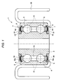
- FIG. 1 is a cross-sectional view illustrating an embodiment of a bearing for an idler pulley, to which a sealing device for a bearing according to a first embodiment of the invention is applied.
- a bearing 1 is used for rotationally supporting an idler pulley for an automobile.
- the bearing 1 is formed to be a double row deep groove ball bearing (radial bearing) to be used such that an inner ring 3 is provided at a non-rotating side, and that an outer ring 4 is provided at a rotating side.
- Balls 5 serving as rolling elements are arranged in a rolling element arranging space 15 formed between the inner ring 3 and the outer ring 4 while the circumferential arrangement integrals thereof are regulated by retainers 6 at the respective rows.
- a pulley 20 is concentrically fit onto the outer circumferential surface of the outer ring 4.
- sealing devices 7 are provided in annular opening 15a that appear at both axial ends of the rolling element arranging space 15, respectively. Any of the sealing devices 7 for a bearing have just the same structure.
- a main part of each of the sealing devices 7 includes an inner ring side slinger 10 and a sliding seal portion 8.
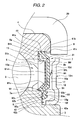
- FIG. 2 is an enlarged and detail cross-sectional view illustrating one of the sealing devices 7 for a bearing.
- the slinger 10 is disposed so as to axially obstruct the annular openings 15a of the rolling element arranging space 15 formed between the inner ring 3 and the outer ring 4.
- a radially inner circumferential edge portion of the slinger 10 is fit to an axial end portion of the inner ring 3 relatively unrotatably therewith.
- the slinger 10 includes a body plate 10m arranged concentrically with the inner ring 3 such that a thickness direction thereof coincides with the axial direction thereof, and a cylindrical portion 10f formed integrally with the body plate 10m so as to axially inwardly protrude from an opening inner circumferential edge of the body plate 10m.
- a radially midway section portion of the body plate 10m expands axially inwardly from both end section portions thereof and serves as an annular reinforcing expansion portion 10d whose inner surface 10a is flattened.
- an annular inner-ring-side step portion 42 is formed on an outer circumferential edge portion of the axial end surface of the inner ring 3.
- a cylindrical portion 10f of the slinger 10 is press-fit into an inner circumferential surface 42a of the inner-ring-side step portion 42.
- the sliding seal portion 8 is arranged so as to face the slinger 10 such that an axial seal clearance 17 is formed at the axially inner side of the slinger 10.
- the radially outer circumferential edge of the sliding seal portion 8 is fit to the axial end portion of the outer ring 4 relatively unrotatably therewith.
- a sub-seal lip 94 made of an elastic polymer material is formed using a surface opposed to the slinger 10 as an axial base surface 8b so as to be inclined radially outwardly away from the axial base surface 8b while crossing the axial seal clearance 17.
- a distal end portion of the sub-seal lip 94 is slide-contacted with an axially inner surface. 10a (constituting the inner surface of the aforementioned reinforcing expansion portion 10d) of the slinger 10.
- the sliding seal portion 8 includes a seal mandrel 81 arranged so that the thickness direction of the seal mandrel 81 coincides with an axial direction thereof, and a seal body 8M made of an elastic polymer material, which covers a plate surface at the axially outer side of the seal mandrel 81.
- the main seal lip 9 is formed integrally with the seal body 8M so as to extend radially inwardly from a radially inner circumferential edge of the seal mandrel 81.
- the sub-seal lip 94 is formed integrally with the seal body 8M using the axially outer surface of the seal body 8M as the axial base surface 8b.
- the seal mandrel 81 includes an annular body plate 81 m arranged such that the thickness direction thereof coincides with the axial direction thereof, a cylindrical wall portion 81 a formed integrally with the body plate 81 m so as to protrude axially inwardly from an outer circumferential edge of the body plate 81m, and a flange portion 81 b extending radially outwardly from the axial edge of the cylindrical wall portion 81a.
- the outer circumferential edge portion of the seal body 8M constitutes an annular cross-sectionally square-shaped fitting lip 8e formed so as to enfold the cylindrical wall portion 81a and the flange portion 81b.
- a reinforcing bent-back portion 81c is formed by axially inwardly and obliquely bending back an inner circumferential edge side portion of the seal mandrel 81.
- the seal body 8M radially inwardly extends while wrapping the reinforcing bent-back portion 81c, thereby to constitute the main seal lip 9.
- An inner circumferential portion of an axially end surface of the outer ring 4 is cut into a circumferentially stepped shape to thereby form an annular outer-ring-side cutout portion 41.
- the fitting lip 8e is press-fit into the outer-ring-side cutout portion 41 so as to be closely contacted with a bottom surface 41 a and an inner circumferential surface 41 b thereof.
- a slip-off preventing rib 41 r is formed on an axial edge portion at an opened side of the inner circumferential surface 41 b of the outer-ring-side cutout portion 41 so as to circumferentially protrude therefrom.
- the fitting lip 8e is fit into the outer-ring-side cutout portion 41 by elastically overriding the slip-off rib 41 r.
- the main seal lip 9 includes base portions 91 extending radially outwardly from the seal body 8M, and an inner lip 92 extending axially inwardly from the base portion 91.
- the inner lip 92 includes an inner slide contact lip 92a that extends from the base portion 91 provided at a radially inner side toward the bottom surface 42b of the inner-ring-side step portion 42 and slide-contacts the bottom surface 42b, an inner auxiliary lip 92b extending from the base portion 91 provided at a radially outer side toward the bottom surface 42b of the inner-ring-side step portion 42, and an axial lip 92c extending from the base portion 91 provided at the radially outer side toward an axially inner side.
- Outer lips 93 include a first outer lip 93a provided in the base portion 91 at the substantially same position as the radial position of the inner slide contact lip 92a so as to extend axially outwardly, and a second outer lip 93b provided in the base portion 91 at the substantially same position as the radial position of the inner auxiliary lip 92b so as to extend axially outwardly.
- the inner lip 92 is configured so that only the inner slide contact lip 92a is slide-contacted with the bottom surface 42b of the inner-ring-side step portion 42, while the inner auxiliary lip 92b is not slide-contacted therewith.
- the inner slide contact lip 92a is worn by a certain amount.
- the inner auxiliary lip 92b is brought into slide contact with the bottom surface 42b of the inner-ring-side step portion 42.
- the axial lip 92c and the outer circumferential surface 3a of the inner ring 3 constitute a labyrinth seal.
- grease is made to adhere to the bottom surface 42b of the inner-ring-side step portion 42 and the inner surface 10a of the slinger 10.
- FIG. 3 is an enlarged cross-sectional view illustrating the sub-seal lip 94.
- FIG. 6 is a further-enlarged cross-sectional view illustrating a distal end portion 94t at the slide contact side of the sub-seal lip 94.
- the sub-seal lip 94 is such that a slide contact edge 94e is formed at a position at which a distal end surface 94c of the sub-seal lip end portion 94t intersects with a radially inner circumferential surface 94a.
- An upper part of FIG. 3 illustrates the sub-seal lip 94 in a virtual non-deformed state in which the slinger 10 is omitted.
- the sub-seal lip 94 is always elastically deformed by the slinger 10 in a non-rotating condition of the bearing.
- the shape of the sub-seal lip 94 in the non-deformed state can be confirmed.
- the slide contact edge 94e is positioned axially outer than the inner surface 10a of the slinger 10 by a certain distance when the non-deformed state occurs (in addition, the non-rotating condition of the bearing simultaneously occurs). An amount, by which the slide contact edge 94e is extended axially from the inner surface of the slinger 10, in the case of estimating in the non-deformed state determines an axially exposed thread ⁇ of the sub-seal lip 94.
- the sub-seal lip 94 is configured such that the distal end portion 94t of the sub-seal lip 94 abuts against the inner surface 10a thereof by employing the side of the slide contact edge 94e as a side from which the distal end portion 94t starts abutting thereagainst and by being elastically deformed while forming an annular band-like slide contact surface 94a' in the radially inner circumferential surface 94a, as illustrated in a lower part of FIG. 3 .
- the distal end surface 94c does not abut against the slinger 10.
- the sub-seal lip 94 When a centrifugal force due to the rotation of the outer ring 4 acts thereon in this state, the sub-seal lip 94 is radially outwardly and elastically deformed, as illustrated in FIG. 4 , that is, the sub-seal lip 94 is elastically deformed so as to be inclined toward the side of the axial base surface 8b. An amount of inclination of the sub-seal lip 94 increases with increase in the centrifugal force. When estimated in the non-deformed state illustrated in FIG. 3 , the axially exposed thread ⁇ of the sub-seal lip 94 decreases with increase in the amount of inclination of the sub-seal lip 94. Then, as indicated by dashed lines in FIG.
- the radial width W0 of the slide surface 94a', in a state in which the outer ring 4 is non-rotated, and the radial width W1 thereof, in a state in which the outer ring 4 rotates and in which a centrifugal force acts satisfy the following condition: W1 ⁇ W0.
- the sub-seal lip 94 implements the function of self-controlling the sealing property and the running torque of the bearing according to the rotation speed of the outer ring 4. That is, the slide contact surface 94a' of the sub-seal lip 94 is formed like an annular band. As the rotation speed of the outer ring 4 increases, the width of the slide contact surface 94a' is radially reduced due to the centrifugal force. Accordingly, the sliding friction can effectively be minimized. The torque of the bearing can be prevented from increasing at high-speed rotation.
- the sub-seal lip 94 can maintain a slide-contacted state.
- the problem of the floating-up of the sub-seal lip 94 from the slinger 10 is difficult to occur.
- the sub-seal lip 94 is put into line contact with the inner surface of the slinger from a slide contact edge 94e formed in the boundary between the distal end surface 94c and the radially inner circumferential surface 94a thereof, instead of bringing the sub-seal lip 94 into plane contact with the inner surface of the slinger in the direction of a normal line thereto from a distal end portion thereof.
- the annular band-like slide contact surface 94a' is formed while the sub-seal lip 94 is elastically deformed. Consequently, even when the width of the slide contact surface 94a' is somewhat reduced due to the centrifugal force, the sealing ability is difficult to be impaired. For example, in a case where a vehicle runs while being submerged in a river, the width of the slide contact surface 94a' becomes sufficiently wide with reduction in the centrifugal force. Consequently, the sealing property of the sub-seal lip 94 can be enhanced. Accordingly, occurrence of the problem of filtration of water filled around the bearing thereinto can effectively be prevented.
- the aforementioned exposed thread ⁇ is adjusted such that the width ⁇ of the clearance formed between the slide contact edge 94e and the inner surface 10a of the slinger 10 at the maximum rotation speed, which is assumed when the bearing is actually used, is sufficient for constituting a labyrinth seal.
- the sub-seal lip 94 is radially inwardly and elastically deformed by the aforementioned negative pressure suction force. Consequently, the radial width W of the annular band-like slide contact surface 94a' formed between the end portion 94t of the sub-seal lip 94 and the slinger 10 can be increased with increase in the negative pressure. Accordingly, the sealing ability at the time of generating the negative pressure can considerably be enhanced. That is, the radial width W' of the slide contact surface 94a' in a case where the negative pressure does not act, and the radial width W" thereof in a case where the negative pressure acts, satisfy the following condition: W" > W.
- a lip length L determined as a dimension to the slide contact edge 94e from a starting position of inclination of the sub-seal lip 94 from the axial base surface 8b in the direction of a generatrix of the radially inner circumferential surface 94a is adjusted to be larger than a lip base end thickness ⁇ determined as a radial dimension of an intersection surface between the lip and the axial base surface 8b.
- the distal end surface 94c of the sub-seal lip 94 is formed to be a flat surface, as illustrated in a left-side part of FIG. 6 . Consequently, the sub-seal lip 94 is configured such that the slide contact edge 94e formed at the position of intersection between the radially inner circumferential surface 94a and the distal end surface 94c can maintain an appropriate stiffness and can be sharpened, and that the effect of improving the sealing property due to the line contact can be enhanced.
- the distal end surface 94c of the sub-seal lip 94 can be formed into a stepped shape.
- a protrusion portion 94f is formed at a side opposite to the side on which the slide contact edge 94e of the distal end surface 94c is formed.
- the distal end surface 94c can be formed to be a convex curved distal end surface 94c'.
- the distal end surface 94c can be formed to be a concave curved distal end surface 94c".
- the sub-seal lip 94 is formed into a shape of a rotating body with respect to the axis line of rotation of the bearing.
- the slide contact edge 94e is defined as follows. That is, when considering a cross-section including an axis line of rotation of the bearing in the non-deformed state, as illustrated in FIG. 6 , a tangential line 10c' (spatially corresponding to a cylindrical surface) circumscribing an outline of the distal end portion 94t of the sub-seal lip 94 including the distal end surface 94c is drawn in parallel to the inner surface of the slinger 10.
- each point (spatially corresponding to a circle) of contact between the tangential line 10c' and the outline at that time constitutes the aforementioned slide contact edge 94e.
- the distal end portion of the sub-seal lip is slide-contacted therewith on a band-like surface 94j constructed such that the chamfered segment has a constant width.
- an edge positioned at the radially inner side of the band-like surface 94j is regarded as the slide contact edge 94e.
- the distal end portion 94t of the sub-seal lip 94 is shaped so that the width of the distal end portion 94t is acutely tapered toward the distal end thereof in a cross-section including the axis line of rotation of the bearing.
- the flexibility of the distal end portion 94t of the sub-seal lip 94 can be improved by forming the distal end portion 94t into a tapered shape.
- the adhesiveness between the distal end portion 94t of the sub-seal lip 94 and the slinger 10 can be enhanced. In the configuration illustrated in FIG.
- the entire sub-seal lip 94 is formed into a wedge-like shape adapted so that the thickness of the sub-seal lip is continuously reduced toward the distal end at the slide-contact side end from the base end side at which the distal end portion 94t is inclined away from the axial substrate surface 8b.
- the lip thickness of the base end portion of the sub-seal lip 94 is large. This can prevent occurrence of the problem that the sub-seal lip 94 is radially reversed in assembling the device. In .addition, the aforementioned effect obtained by tapering the distal end portion of the sub-seal lip can simultaneously be achieved. Incidentally, as illustrated in FIGS.
- FIG. 11 illustrates an example of forming the predetermined segment portion, which includes the distal end portion of the sub-seal lip, so that the lip thickness is uniform.
- FIG. 12 illustrates an example of tapering the distal end portion of the lip.
- the sub-seal lip 94 is configured so as to form the outline in the non-deformed state like a straight line such that an acute-side angle ⁇ 1 of intersection between the outline indicating the radial inner circumferential surface 94a and the axial base surface 8b is smaller than an acute-side angle ⁇ 2 of intersection between the outline indicating the radial outer circumferential surface and the axial base surface 8b.
- the entire sub-seal lip 94 or the distal end portion 94t can be formed into a shape in which the sub-seal lip 94 or the distal end portion 94t is flexed toward the radially inner circumferential surface 94a at the side at which the sub-seal lip 94 or the distal end portion 94t abuts against the slinger 10, as illustrated in FIG. 9 .
- the sub-seal lip 94 or the distal end portion 94t can be formed into a preliminarily curved shape so as to expand toward the radially inner circumferential surface 94a, as illustrated in FIG. 10 .
- the second embodiment differs from the first embodiment mainly in the configuration of the sub-seal lip: Thus, the following description centers on the configuration of the sub-seal lip.
- Each component common to the first and second embodiments is designated with the same reference numeral. The description of such components is omitted.
- FIG 13 is an enlarged cross-sectional view illustrating a sealing device portion for a bearing according to a second embodiment of the invention.
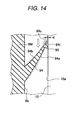
- FIG. 14 is an enlarged cross-sectional view illustrating a sub-seal lip of the sealing device for a bearing illustrating in FIG. 13 .
- annular branch seal lip 95 is formed at a radially midway position on the inner circumferential surface of the sub-seal lip 94 so as to protrude toward the inner surface of the slinger 10. In a case where the outer ring 4 is in a non-rotating state, a. distal end of the branch seal lip 95 is slide-contacted with the inner surface of the slinger 10.
- a radially inner circumferential surface of the distal end portion 94t of the sub-seal lip is positioned closer to the side of the radially distal end than the branch seal lip 95 of the sub-seal lip 94 such that the distance between the inner surface of the slinger 10 and the radially inner circumferential surface of the distal end portion 94t is gradually reduced toward the distal end of the sub-seal lip 94.
- the distal end portion 94t of the sub-seal lip 94 is configured so that a clearance ⁇ constituting a labyrinth seal is formed between the radially inner circumferential end edge of the distal end portion 94t of the sub-seal lip and the inner surface of the slinger 10.
- the distal end portion 94t of the sub-seal lip 94 has been non-contacted with the slinger 10. Even when the outer ring 4 is put into a rotating state, the sub-seal lip 94 is inclined toward the axial base surface 8b, i.e., in a direction in which the sub-seal lip 94 is inclined away from the slinger 10, as indicated by dashed lines in FIG. 15 , so that the sub-seal lip 94 is deformed. Accordingly, the distal end portion 94t is not put into a state in which the distal end portion 94t and the slinger 10 slide with each other.
- the annular branch seal lip 95 is formed on the radially inner circumferential surface of the sub-seal lip 94 so as to protrude toward the inner surface of the slinger 10.
- the distal end of the branch seal lip 95 constitutes a linear slide contact surface against the slinger 10.
- the axial exposed thread of the branch seal lip 95 is increased.
- the distal end portion 94t of the sub-seal lip 94 maintains a state in which the distal end portion 94t is non-contacted with the slinger 10.
- a lip slide contact area is difficult to be excessively large. Consequently, occurrence of a stick-slip phenomenon can effectively be restrained.
- FIG. 16 an example is shown, in which the radial inner circumferential distal edge of the distal end portion 94t of the sub-seal lip 94 is slide-contacted with the inner surface of the slinger 10, together with the branch seal lip 95, across a groove 99 formed by the radial inner circumferential surface and the radial outer circumferential surface of the branch seal lip 95.
- the sub-seal lip 94 is such that a slide contact edge 94e is formed at a position at which the distal end surface 94c of the distal end portion 94t of the sub-seal lip 94 and the radial inner circumferential surface 94a intersect with each other.
- the position of the distal end of the sub-seal lip 94 in the virtual non-deformed state in which the slinger 10 is omitted is indicated by an alternate long and short dash line in FIG. 16 .
- the sub-seal lip 94 is made by the slinger 10 to be always in an elastically deformed condition in the non-rotating state of the bearing.
- the shape of the sub-seal lip 94 in the non-deformed state can be confirmed with removal of the slinger 10.
- the slide contact edge 94e is placed outwardly from the position of the inner surface 10a of the slinger 10 by a certain distance in an axial direction in the non-deformed state (simultaneously in the non-rotating state of the bearing).
- An amount of axial extension of the slide contact edge 94e from the inner surface of the slinger 10 in the case of estimating in the non-deformed state determines an axial exposed thread ⁇ of the distal end portion 94t of the sub-seal lip 94 in the non-rotating state in which the outer ring 4 is not rotate (simultaneously, the negative pressure is 0).
- the distal end portion 94t of the sub-seal lip 94 abuts against the inner surface 10a of the slinger 10 by being elastically deformed while forming the annular band-like slide contact surface 94a' on the radially inner circumferential surface 94a by employing the slide contact edge 94e as a side at which the abutment of the distal end portion is started.
- the distal end surface 94c of the distal end portion 94t does not abut against the slinger 10.
- the distal end surface 94c is formed to be a flat surface.
- the aforementioned slide contact edge 94e is sharpened while appropriate stiffness is maintained. This contributes to the enhanced sealing property employing line contact.
- the sub-seal lip 94 When a centrifugal force generated by the rotation of the outer ring 4 acts on the sub-seal lip 94, the sub-seal lip 94 is radially outwardly and elastically deformed, that is, deformed so as to be inclined toward the axial base surface 8b (see FIG. 14 ), as illustrated in FIG. 17 .
- the axial exposed thread ⁇ is reduced with increase in the amount of inclination of the sub-seal lip 94.
- the radially inner circumferential surface 94a of the distal end portion 94t is radially turned out from a side opposite to the slide contact edge 94e while the position, at which the slide contact edge 94e abuts against the inner surface 10c, is substantially maintained.
- the sub-seal lip 94 can maintain a slide-contacted state.
- the problem of the floating-up of the sub-seal lip 94 from the slinger 10 is difficult to occur.
- the sub-seal lip 94 is put into line contact with the inner surface of the slinger from a slide contact edge 94e formed in the boundary between the distal end surface 94c and the radially inner circumferential surface 94a thereof, instead of bringing the sub-seal lip 94 into plane contact with the inner surface of the slinger in the direction of a normal line thereto from a distal end portion thereof.
- annular band-like slide contact surface 94a' is formed while the sub-seal lip 94 is elastically deformed. Consequently, even when the width of the slide contact surface 94a' is somewhat reduced due to the centrifugal force, the sealing ability is difficult to be impaired.
- distal end portion 94t of the sub-seal lip 94 and the branch seal lip 95 radially constitute a type of a two-stage seal.
- the sub-seal lip 94 is deformed radially inwardly (i.e., in a direction in which the sub-seal lip 94 is pushed against the slinger 10), as indicated by dashed lines in FIG. 16 .
- the exposed thread of the branch seal lip 95 increases.
- the distal end portion 94t of the sub-seal lip 94 swings with respect to the inner surface of the slinger 10 in a direction, in which the distal end portion 94t goes away from the inner surface of the inner-ring-side 10 as the negative pressure acting on the sub-seal lip 94 increases; by employing the branch seal lip 95 as a fulcrum point. Consequently, the axial exposed thread of the distal end portion 94t of the sub-seal lip 94 at the time of causing the negative pressure to act is reduced by the swinging motion of the distal end portion 94t. Accordingly, a stick-slip phenomenon is difficult to occur.
- the third embodiment differs from the first embodiment mainly in the configuration of each of the sub-seal lip and the slinger.
- the following description centers on the configuration of the sub-seal lip and the slinger
- Each component common to the first and third embodiments is designated with the same reference numeral. The description of such components is omitted.
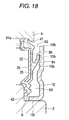
- a conical sub-seal lip 94 whose diameter is increased toward the outer side of the bearing in a state; in which the sliding seal portion 8 is not mounted in the rolling bearing 1, as indicated by imaginary lines in FIG. 18 , is formed at a radially central portion of the axial base surface 8b of the sliding seal portion 8, which faces the slinger 10, at the outer side of the bearing. Further, in a state in which the sliding seal portion 8 is mounted in the rolling bearing 1, the distal end portion of the sub-seal lip 94 is deformed to be flat, as indicated by solid lines in FIG. 18 .
- the sub-seal lip 94 is contacted with the inner surface 10a of the sub-seal lip 94, which is placed at the inner side of the bearing, in a state in which a predetermined exposed thread is set, and in which the sub-seal lip 94 is pressurized.
- the distal end of the sub-seal lip 94 and the inner surface 10a of the slinger 10 are brought into slight contact with each other in order to allow the relative rotation between the sliding seal portion 8 and the slinger 10.
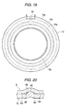
- FIG. 19 is a plan view illustrating the inside of the bearing of the slinger 10.
- the slinger 10 is an annular metal plate formed by press-working. Further, as illustrated in FIG. 18 , a circumferential end of the slinger 10 is bent like a cylinder toward the inner side of the rolling bearing 1 to thereby form a cylindrical portion 10f. The cylindrical portion 10f is press-fit into an outside-diameter-side of the inner ring 3. Thus, the slinger 10 is fixed to the inner ring 3. Further, a clearance is provided between a distal end portion 10b at an end of the outside-diameter-side of the slinger 10 and the outer ring 4. Consequent an opening portion 62 opened toward the outside of the bearing is formed.
- an end of the sub-seal lip 94 of the sliding seal portion 8 is contacted with the inner surface 10a of the slinger 10, which is placed at the inner side of the bearing, to thereby block up the clearance between the sliding seal portion 8 and the slinger 10.
- a sealed area 64 surrounded by the sliding seal portion 8 and the slinger 10 is formed at the inside-diameter-side more inwardly from the sub-seal lip 94 by being obstructed by the sub-seal lip 94.
- FIG. 20 is a partial cross-sectional view which is taken on a position A-A shown in FIG. 21 , and which illustrates the sub-seal lip 94 of the sliding seal portion 8 and the slinger 10. As illustrated in FIG 20 , an airflow path.
- the sealed area 64 an air hole is formed in the periphery of the protrusion 60 of the slinger 10. Accordingly, the sealed area 64 is configured to communicate with outside air.
- FIG. 21 is a partial cross-sectional view that illustrates a part of the rolling bearing 1, which is parallel to a shaft, and that is taken in a position, at which the protrusion 60 is formed on the slinger 10.
- the sub-seal lip 94 of the sliding seal portion 8 is sprang onto the protrusion 60 and is separated from the inner surface 10a of the slinger 10. Further, the airflow path 66 is formed between the sub-seal lip 94 and the slinger 10 so as to extend in a front-back direction of paper on which FIG. 21 is drawn.
- the inner ring 3 does not rotate.
- the position of the protrusion 60 of the slinger 10 fixed to the inner ring 3 does not change.
- the rolling bearing 1 is attached to the shaft such that the protrusion 60 is located below the rolling bearing 1.
- water is prevented from infiltrating, when the water is splashed on the bearing 1, into the bearing 1 from the periphery of the protrusion 60.
- a plurality of protrusions 60 can be formed on the seal sliding surface 10h of the slinger 10.
- the sliding seal portion 8 fixed to the outer ring 4 rotates at high speed due to the high-speed rotation of the bearing 1. Also, the main seal lip 9 and the sub-seal lip 94 rotate at high speed. Then, air in the sealed area 64 is heated by heat generated due to the sliding motion of the main seal lip 9 on the inner ring 3 and that of the sub-seal lip 94 on the slinger 10. Thus, the internal pressure of the sealed area 64 becomes higher than the atmosphere pressure.
- air in the sealed area 64 leaks out of the airflow path 66 provided in the periphery of the position, at which the sub-seal lip 94 slides on the protrusion 60, to the outside-diameter side of the sub-seal lip 94.
- the difference in pressure between the air in the sealed area 64 and the atmospheric air can be eliminated.
- the protrusion provided on the inner surface 10a of the slinger 10 is formed like a hemisphere.
- the shape of the protrusion 60 is not limited thereto.
- the protrusion 60 can be formed into a shape in which each semicircular cross-section extends radially.
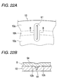
- FIG. 22A is a partial plan view illustrating the slinger 10 provided with the ventilating groove 61 in the bearing as an example of modification of the embodiment.
- FIG. 22B is a partially cross-sectional view illustrating the sub-seal lip'94 of the sliding seal portion 8 and the slinger 10 at a position B-B shown in FIG 22A .
- the ventilating groove 61 is shaped so as not to be blocked up by the sub-seal lip 94.
- a plurality of ventilating grooves 61 can be formed.
- a slinger fit onto the inner ring is used as the slinger on which the main seal lip slides.
- the slinger can be a shield plate whose inner circumference is fixed directly to the shaft.
- a sealing device for a rolling bearing according to the invention can be implemented in various modes within the scope of the idea of the invention.
- the fourth embodiment differs from the first embodiment mainly in the configuration of the sub-seal lip.
- the following description centers on the configuration of the sub-seal lip.
- Each component common to the first and fourth embodiments is designated with the same reference numeral. The description of such components is omitted.
- a conical sub-seal lip 94 whose diameter is increased toward the outer side of the bearing, is formed at a radially central portion of the axial base surface 8b of the sliding seal portion 8, which faces the slinger 10, at the outer side of the bearing.
- the sliding surface 10h at the distal end of the sub-seal lip 94 is contacted with the inner surface 10a of the slinger 10, which is placed at the inner side of the bearing.
- the sliding surface 10h of the sub-seal lip 94 and the inner surface 10a of the singer 10 are brought into slight contact with each other in order to allow the relative rotation between the sliding seal portion 8 and the slinger 10.
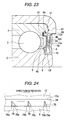
- восем ⁇ triangular plate-like fins 78 are formed at uniform intervals so as to be circumferentially separated from one another and as to extend between the axial base surface 8b of the sliding seal portion 8 and the sub-seal lip 94. Incidentally, the interval between and the number of the fins 78 can appropriately be changed.
- FIG. 24 is a view taken in the direction of arrow A illustrated in FIG. 23 .
- the fins 78 are formed so as to be inclined to the radial direction.
- the inside-diameter-side base portion 78a of each fin 78 is provided at the front side in the direction of rotation of the sliding seal portion 8.
- the outside-diameter-side distal end portion 78b of each fin 78 is provided at the rear side in the direction of rotation of the sliding seal portion 8.
- the slinger 10 is an annular metal plate.
- a circumferential end of the slinger 10 is bent like a cylinder toward the inner side of the rolling bearing 1 to thereby form a cylindrical portion 10f.
- the cylindrical portion 10f is press-fit into the outside-diameter-side of the inner ring 3.
- the slinger 10 is fixed to the inner ring 3.
- a clearance is provided between the distal end portion 10b at an end of the outer circumference of the slinger 10 and an end surface of a flange 42 of the idler pulley 20. Consequently, an opening portion 88 is formed so as to be opened toward the outside of the bearing.
- the sliding surface 10h of the sub-seal lip 94 of the sliding seal portion 8 is contacted with the inner surface 10a of the slinger 10, which is placed at the inner side of the bearing, to thereby block up the clearance between the sliding seal portion 8 and the slinger 10.
- the sliding surface 10h of the distal end portion of the sub-seal lip 94 formed on the axial base surface 8b, which faces the slinger 10 of the sliding seal portion 8, is contacted with the inner surface 10a of the slinger 10, which is provided at the inner side of the bearing, thereby blocking up the clearance between the sliding seal portion 8 and the slinger 10.
- foreign materials such as water and dust, entering between the sliding seal portion 8 and the slinger 10 from the outside-diameter-side opening portion 88 are restrained from infiltrating into the vicinity of the seal lip 94 which is provided at the inside-diameter side of the bearing.
- the sliding seal portion 8 is fixed to the outer ring 4 and rotates together with the outer ring 4.
- the plate-like fins 78 are formed at the base portion of the sub-seal lip 94, which is connected to the axial base surface 8b of the sliding seal portion 8, so as to be circumferentially separated from one another and as to extend between the axial base surface 8b of the sliding seal portion 8 and the sub-seal lip 94. Consequently, air being present between the sliding seal portion 8 and the slinger 10 is sent radially outwardly by the action of rotation of each fin 78 due to the rotation of the sliding seal portion 8.
- the fins 78 are formed by being inclined toward the radial direction such that the rear in the direction of rotation of the sliding seal portion 8 is located at a radially outer side. Consequently, foreign materials are pushed radially outwardly along each fin 78 by the inertia force and are discharged to the outside of the bearing. Accordingly, in a case where the rolling bearing 1 is used in the environment in which a large amount of water is splashed on the bearing, water can effectively be discharged to the outside of the bearing.
- the sub-seal lip 94 is formed at the radially central portion of the axial base surface 8b of the sliding seal portion 8.
- the position at which the sub-seal lip 94 is formed is not limited to the radially central portion of the axial base surface 8b of the sliding seal portion 8.
- the shape of the sub-seal lip 94 is not limited to a conical shape.
- the sub-seal lip 94 can be shaped so that a part thereof, which is close to the base thereof connected to the axial base surface 8b, is cylindrical, and that the diameter thereof increases toward a distal end thereof.
- each fin 78 is inclined to the radial direction.
- the direction of each fin 78 can be a radial direction lined up with the direction of a radius thereof.
- portions respectively having negative angles with respect to, e.g., a demolding direction are reduced. Consequently, the molding of the sliding seal portion 8 is facilitated.
- a clearance is formed between the distal end portion 10b of the slinger 10 and the flange 42 of the pulley 20.
- the device can be configured such that the outer ring 4 is substantially equal in width to the inner ring 3, and that a clearance is formed between the distal end portion 10b of the slinger 10 and the inner surface of the outer ring 4.
- the slinger 10 is fixed to the inner ring 3 by being press-fit thereinto.
- the slinger 10 can be configured such that an end thereof at the side of the inner ring 3 is supported by being surrounded with a snap ring fixed to the axial base surface and the shaft of the inner ring 3.
- the sealing device for a rolling bearing according to the invention is not limited to an idler pulley.
- the rolling bearing is not limited to a double row deep groove ball bearing.
- the sealing device for a rolling bearing according to the invention can be applied to general rolling bearings of the outer ring rotation type.
- a sealing device for a rolling bearing according to the invention can be implemented in various modes within the scope of the idea of the invention.
Landscapes
- Engineering & Computer Science (AREA)
- General Engineering & Computer Science (AREA)
- Mechanical Engineering (AREA)
- Sealing Of Bearings (AREA)
Abstract
Description
- This invention relates to a sealing device for a bearing.
- Demands for size and weight reduction and interior space expansion of each automobile have forced automobiles to reduce the space of each engine room thereof. The size and weight reduction of electrical components and engine accessories have been more advanced. An electromagnetic clutch, a compressor, and an idler pulley for a car air-conditioner are not exceptions. However, a reduction in an output thereof due to the size reduction is inevitable. The reduction of the output of the electromagnetic clutch is compensated by acceleration thereof. Thus, the idler pulley is accelerated. Further, demands for enhancing quietness promote the sealing of the engine room and accelerate the raising of the temperature in the engine room. Consequently, these components need to bear high temperature. In addition, these components are often attached to a lower portion of the engine room. Accordingly, while the automobile runs, rainwater or muddy water is likely to be poured onto these components. Thus, high sealing properties are required by rolling bearings for these components.
- A rolling bearing for the idler pulley is used in a manner in which an inner ring is provided at a non-rotating side, while an outer ring is provided at a rotating side. A sealing device for such a rolling bearing has a sliding seal portion configured so that a radially outer circumferential edge part thereof is fit to an inner circumferential side of an axial end portion of the outer ring relatively unrotatably therewith, and that a main rubber seal lip formed on a radially inner circumferential side thereof is slide-contacted with an outer circumferential side of an axial end portion of the inner ring.
JP-A-2003-194077 - In recent years, operating conditions of automobiles have tended to become more severe. Higher waterproofing property has become desired by a bearing sealing device in consideration of cases where an amount of water to which an automobile is subjected is assumed to be more increased; e.g., where muddy water is splashed on the automobile, and where car wash water is sprayed onto the automobile, or cases where the automobile is used in a water-damaged or submerged state which is found in a recreational vehicle (RV) or the like. An apparatus disclosed in
JP-A-2005-282669 - However, the apparatus disclosed in
JP-A-2005-282669 - (1) A sub-seal lip is added to the apparatus in addition to a main seal lip. Thus, frictional sliding parts between the inner and outer rings are increased. Consequently, bearing torque is increased. Accordingly, there is a fear that this may be a hindrance to high-speed rotation performance. More particularly, when an axially exposed thread of the sub-seal lip is increased to enhance the waterproofing property, the sliding friction of the seal lip is further increased. Thus, the problem of increase in torque becomes marked.
- (2) In the apparatus disclosed in
JP-A-2005-282669 - Further, sealing devices for a bearing are disclosed also in, e.g.,
JP-A-2005-325924 JP-A-11-230279 - An object of the invention is to provide a sealing device for a bearing, which can appropriately self-control the sealing property of the bearing according to the rotation speed thereof and can achieve both of higher sealing property at low-speed rotation and lower running torque at high-speed rotation.
- To solve the aforementioned problems, the present invention provides the following arrangements.
- (1) A sealing device for a radial bearing including an inner ring, an outer ring and rolling elements interposed between the inner and outer rings, the sealing device comprising:
- a slinger which includes a radially inner circumferential edge portion fit to the inner ring and a body plate for axially obstructing an annular opening formed between the inner and outer rings; and
- a sliding seal portion which includes:
- an axial base surface facing the body plate of the slinger with forming an axial seal clearance between the axial base surface and the body plate at an axially inner side of the slinger;
- a radially outer circumferential edge which is formed at an radially outer end of the axial base surface and is fit to the outer ring;
- a main seal lip which is formed at an radially inner end of the axial base surface and is slide-contacted with an outer side of an axial end portion of the inner ring; and
- a sub-seal lip which extend from the axial base surface in the axial seal clearance so that a slide contact edge at a distal end portion of the sub-seal lip is slide-contacted with the body plate,
wherein the sub-seal lip is elastically deformed so as to be inclined toward the axial base surface by a centrifugal force generated due to rotation of the outer ring, and
wherein a radial width of the annular band-like shape of the slide contact area is reduced toward the slide contact edge with increase in the centrifugal force. - (2) The sealing device according to (1), wherein a lip length determined as a dimension to the slide contact edge from a starting position of inclination of the lip is larger than a lip base end thickness determined as a radial dimension of an intersection surface between the sub-seal lip and the axial base surface.
- (3) The sealing device according to (1), wherein the distal end portion of the sub-seal lip is formed so as to be a flat surface or into a stepped shape.
- (4) The sealing device according to (1), wherein the distal end portion of the sub-seal lip is shaped so that a width of the distal end portion is acutely tapered toward the distal end of the sub-seal lip in a cross-section including an axis line of rotation of the bearing.
- (5) A sealing device for a radial bearing including an inner ring, an outer ring and rolling elements interposed between the inner and outer rings, the sealing device comprising:
- a slinger which includes a radially inner circumferential edge portion fit to the inner ring and a body plate for axially obstructing an annular opening formed between the inner and outer rings; and
- a sliding seal portion which includes:
- an axial base surface facing the body plate of the slinger with forming an axial seal clearance between the axial base surface and the body plate at an axially inner side of the slinger;
- a radially outer circumferential edge which is formed at an radially outer end of the axial base surface and is fit to the outer ring;
- a main seal lip which is formed at an radially inner end of the axial base surface and is slide-contacted with an outer side of an axial end portion of the inner ring; and
- a sub-seal lip which extend from the axial base surface in the axial seal clearance,
wherein when in a non-rotating state of the outer ring, a distal end of the branch seal lip is slide-contacted with the inner surface of the body plate of the slinger, and a distance between the inner surface of the body plate and a radially inner circumferential surface of a distal end portion of the sub-seal lip is gradually reduced toward a distal end of the sub-seal lip. - (6) The seating device according to (5), wherein, in the non-rotating state of the outer ring, a clearance constituting a labyrinth seal is formed between the radially inner circumferential end edge of the distal end portion and the inner surface of the body plate.
- (7) The sealing device according to (5), wherein, in the non-rotating state of the outer ring, a distal end edge of the distal end portion of the sub-seal lip is slide-contacted with the inner surface of the slinger, together with the branch seal lip, across an annular groove formed by the radially inner circumferential surface and the radially outer circumferential surface of the branch seal lip.
- (8) The sealing device according to (7), wherein
the sub-seal lip is elastically deformed in a radially inward direction due to a negative pressure generated at a space where rolling elements are arranged, and
the distal end portion of the sub-seal lip approaches and moves apart from the inner surface of the body plate according to the negative pressure in a swinging manner using the branch seal lip as a fulcrum point. - (9) The sealing device according to (7), wherein
a slide contact edge which is slide-contacted with an axially inner surface of the body plate is formed at the distal end portion of the sub-seal lip,
the sub-seal lip abuts against the inner surface of the body plate by being elastically deformed such that a slide contact area between the slide contact edge and the inner surface of the body plate is an annular band-like shape;
the sub-seal lip is elastically deformed so as to be inclined toward the axial base surface by a centrifugal force generated due to rotation of the outer ring, and
a radial width of the annular band-like shape of the slide contact area is reduced toward the slide contact edge with increase in the centrifugal force. - (10) A sealing device for a radial bearing including an inner ring, an outer ring and rolling elements interposed between the inner and outer rings, the sealing device comprising:
- a slinger which includes a radially inner circumferential edge portion fit to the inner ring and a body plate for axially obstructing an annular opening formed between the inner and outer rings; and
- a sliding seal portion which includes:
- an axial base surface facing the body plate of the slinger with forming an axial seal clearance between the axial base surface and the body plate at an axially inner side of the slinger;
- a radially outer circumferential edge which is formed at an radially outer end of the axial base surface and is fit to the outer ring;
- a main seal lip which is formed at an radially inner end of the axial base surface and is slide-contacted with an outer side of an axial end portion of the inner ring; and
- a sub-seal lip which extend from the axial base surface in the axial seal clearance so that the sub-seal lip is slide-contacted with the body plate,
- (11) A sealing device for a radial bearing including an inner ring, an outer ring and rolling elements interposed between the inner and outer rings, the sealing device comprising:
- a slinger which includes a radially inner circumferential edge portion fit to the inner ring and a body plate for axially obstructing an annular opening formed between the inner and outer rings; and
- a sliding seal portion which includes:
- an axial base surface facing the body plate of the slinger with forming an axial seal clearance between the axial base surface and the body plate at an axially inner side of the slinger;
- a radially outer circumferential edge which is formed at an radially outer end of the axial base surface and is fit to an axial end portion of the outer ring;
- a main seal lip which is formed at an radially inner end of the axial base surface and is slide-contacted with an outer side of an axial end portion of the inner ring; and
- a conical sub-seal lip which extend from the axial base surface in the axial seal clearance so that the sub-seal lip increases in diameter toward a radially outside of the bearing and a slide contact edge at a distal end portion of the sub-seal lip is slide-contacted with the body plate,
wherein air between the sliding seal portion and the slinger is radially outwardly sent out by action of rotation of each fin due to rotation of the sliding seal portion, and
wherein a pressure of the air between the sliding seal portion and the' slinger is made to be higher than a pressure of outside air so as to cause a pressure difference therebetween, thereby restraining a foreign material from infiltrating into between the sliding seal portion and the slinger from an exterior of the bearing. - (12) The sealing device according to (11), wherein
the fins are formed so as to be inclined with respect to a radial direction so that a foreign material entering between the axial base surface of the sliding seal portion and the sub-seal lip in response to a rotation of the sliding seal portion is discharged outwardly in a radial direction of the bearing. -
-
FIG. 1 is a cross-sectional view illustrating a bearing for an idler pulley, to which a sealing device for a bearing according to a first embodiment of the invention is applied. -
FIG. 2 is an enlarged cross-sectional view illustrating a sealing device portion for a bearing, which is illustrated inFIG. 1 . -
FIG. 3 is an enlarged cross-sectional view illustrating both of a non-deformed state and a mounted state of a sub-seal lip of the sealing device for a bearing device illustrated inFIG. 2 . -
FIG. 4 is an explanatory view illustrating an operation of the sub-seal lip. -
FIG. 8 is an explanatory view illustrating an operation performed by the sub-seal lip when a centrifugal force is more increased. -
FIG. 6 is an enlarged cross-sectional view illustrating a first example of the shape of a distal end of the sub-seal lip. -
FIG. 7 is an enlarged cross-sectional view illustrating a second example of the shape of a distal end of the sub-seal lip. -
FIG. 8 is an enlarged cross-sectional view illustrating a third example of the shape of a distal end of the sub-seal lip. -
FIG 9 is an enlarged cross-sectional view illustrating an example of modification of a sub-seal lip that is preliminarily bend-formed. -
FIG. 10 is an enlarged view illustrating a distal end part of modification of a sub-seal lip that is preliminarily curve-formed. -
FIG. 11 is a cross-sectional view illustrating another example of modification of the sub-seal lip. -
FIG. 12 is a cross-sectional view illustrating still another example of modification of the sub-seal lip. -
FIG. 13 is an enlarged cross-sectional view illustrating a sealing device portion for a bearing according to a second embodiment of the invention. -
FIG 14 is an enlarged cross-sectional view illustrating a sub-seal lip of the sealing device for a bearing illustrating inFIG. 13 . -
FIG. 15 is a further-enlarged cross-sectional view illustrating the neighborhood of a distal end portion of the sub-seal lip. -
FIG 16 is a cross-sectional view illustrating an example of modification of the sub-seal lip whose distal end portion is caused to abut against a slinger. -
FIG. 17 is an explanatory view illustrating an operation of the sub-seal lip of a configuration illustrated inFIG. 16 . -
FIG. 18 is an enlarged view illustrating a portion relating to a sealing device for a rolling bearing according to a third embodiment of the invention. -
FIG. 19 is a plan view illustrating the inside of a slinger according to an embodiment of the invention. -
FIG. 20 is a partial cross-sectional view which is taken in a position A-A illustrated inFIG. 19 and which illustrates a sliding seal portion and a slinger. -
FIG. 21 is a partial cross-sectional view that illustrates a part of a rolling bearing, which is parallel to a shaft, and that is taken in a position, at which a protrusion is formed on a slinger. -
FIG. 22A is a partial plan view illustrating the inside of a bearing of a slinger of a modified embodiment of the invention.Fig. 22B is a partial cross-sectional view that is taken in a position B-B illustrated inFIG. 22A and that illustrates a sliding seal portion and a slinger. -
FIG. 23 is an enlarged view illustrating a portion relating to a sealing device for a rolling bearing according to a fourth embodiment of the invention. -
FIG. 24 is a view taken in the direction of arrow A illustrated inFIG. 23 . - Hereinafter, embodiments of the invention are described with reference to the accompanying drawings.
FIG. 1 is a cross-sectional view illustrating an embodiment of a bearing for an idler pulley, to which a sealing device for a bearing according to a first embodiment of the invention is applied. Abearing 1 is used for rotationally supporting an idler pulley for an automobile. Thebearing 1 is formed to be a double row deep groove ball bearing (radial bearing) to be used such that aninner ring 3 is provided at a non-rotating side, and that anouter ring 4 is provided at a rotating side.Balls 5 serving as rolling elements are arranged in a rollingelement arranging space 15 formed between theinner ring 3 and theouter ring 4 while the circumferential arrangement integrals thereof are regulated byretainers 6 at the respective rows. Apulley 20 is concentrically fit onto the outer circumferential surface of theouter ring 4. - In the .
bearing 1, sealingdevices 7 are provided inannular opening 15a that appear at both axial ends of the rollingelement arranging space 15, respectively. Any of thesealing devices 7 for a bearing have just the same structure. A main part of each of thesealing devices 7 includes an innerring side slinger 10 and a slidingseal portion 8. -
FIG. 2 is an enlarged and detail cross-sectional view illustrating one of thesealing devices 7 for a bearing. Theslinger 10 is disposed so as to axially obstruct theannular openings 15a of the rollingelement arranging space 15 formed between theinner ring 3 and theouter ring 4. A radially inner circumferential edge portion of theslinger 10 is fit to an axial end portion of theinner ring 3 relatively unrotatably therewith. More specifically, theslinger 10 includes abody plate 10m arranged concentrically with theinner ring 3 such that a thickness direction thereof coincides with the axial direction thereof, and acylindrical portion 10f formed integrally with thebody plate 10m so as to axially inwardly protrude from an opening inner circumferential edge of thebody plate 10m. A radially midway section portion of thebody plate 10m expands axially inwardly from both end section portions thereof and serves as an annular reinforcingexpansion portion 10d whoseinner surface 10a is flattened. Further, an annular inner-ring-side step portion 42 is formed on an outer circumferential edge portion of the axial end surface of theinner ring 3. Acylindrical portion 10f of theslinger 10 is press-fit into an innercircumferential surface 42a of the inner-ring-side step portion 42. - Next, the sliding
seal portion 8 is arranged so as to face theslinger 10 such that anaxial seal clearance 17 is formed at the axially inner side of theslinger 10. The radially outer circumferential edge of the slidingseal portion 8 is fit to the axial end portion of theouter ring 4 relatively unrotatably therewith. Amain seal lip 9 made of an elastic polymer material, which is slide-contacted with the outer side of an axial end portion of theinner ring 3, is formed on the radially outer circumferential edge side of the slidingseal portion 8. Asub-seal lip 94 made of an elastic polymer material is formed using a surface opposed to theslinger 10 as anaxial base surface 8b so as to be inclined radially outwardly away from theaxial base surface 8b while crossing theaxial seal clearance 17. A distal end portion of thesub-seal lip 94 is slide-contacted with an axially inner surface. 10a (constituting the inner surface of the aforementioned reinforcingexpansion portion 10d) of theslinger 10. - More specifically, the sliding
seal portion 8 includes aseal mandrel 81 arranged so that the thickness direction of theseal mandrel 81 coincides with an axial direction thereof, and aseal body 8M made of an elastic polymer material, which covers a plate surface at the axially outer side of theseal mandrel 81. Themain seal lip 9 is formed integrally with theseal body 8M so as to extend radially inwardly from a radially inner circumferential edge of theseal mandrel 81. Further, thesub-seal lip 94 is formed integrally with theseal body 8M using the axially outer surface of theseal body 8M as theaxial base surface 8b. - The
seal mandrel 81 includes anannular body plate 81 m arranged such that the thickness direction thereof coincides with the axial direction thereof, acylindrical wall portion 81 a formed integrally with thebody plate 81 m so as to protrude axially inwardly from an outer circumferential edge of thebody plate 81m, and aflange portion 81 b extending radially outwardly from the axial edge of thecylindrical wall portion 81a. The outer circumferential edge portion of theseal body 8M constitutes an annular cross-sectionally square-shapedfitting lip 8e formed so as to enfold thecylindrical wall portion 81a and theflange portion 81b. On the other hand, a reinforcing bent-back portion 81c is formed by axially inwardly and obliquely bending back an inner circumferential edge side portion of theseal mandrel 81. Theseal body 8M radially inwardly extends while wrapping the reinforcing bent-back portion 81c, thereby to constitute themain seal lip 9. - An inner circumferential portion of an axially end surface of the
outer ring 4 is cut into a circumferentially stepped shape to thereby form an annular outer-ring-side cutout portion 41. Thefitting lip 8e is press-fit into the outer-ring-side cutout portion 41 so as to be closely contacted with abottom surface 41 a and an innercircumferential surface 41 b thereof. Incidentally, a slip-off preventingrib 41 r is formed on an axial edge portion at an opened side of the innercircumferential surface 41 b of the outer-ring-side cutout portion 41 so as to circumferentially protrude therefrom. Thefitting lip 8e is fit into the outer-ring-side cutout portion 41 by elastically overriding the slip-offrib 41 r. - The
main seal lip 9 includesbase portions 91 extending radially outwardly from theseal body 8M, and aninner lip 92 extending axially inwardly from thebase portion 91. Theinner lip 92 includes an innerslide contact lip 92a that extends from thebase portion 91 provided at a radially inner side toward thebottom surface 42b of the inner-ring-side step portion 42 and slide-contacts thebottom surface 42b, an innerauxiliary lip 92b extending from thebase portion 91 provided at a radially outer side toward thebottom surface 42b of the inner-ring-side step portion 42, and anaxial lip 92c extending from thebase portion 91 provided at the radially outer side toward an axially inner side.Outer lips 93 include a firstouter lip 93a provided in thebase portion 91 at the substantially same position as the radial position of the innerslide contact lip 92a so as to extend axially outwardly, and a secondouter lip 93b provided in thebase portion 91 at the substantially same position as the radial position of the innerauxiliary lip 92b so as to extend axially outwardly. - The
inner lip 92 is configured so that only the innerslide contact lip 92a is slide-contacted with thebottom surface 42b of the inner-ring-side step portion 42, while the innerauxiliary lip 92b is not slide-contacted therewith. After thebearing 1 is started to be used, the innerslide contact lip 92a is worn by a certain amount. Thus, the innerauxiliary lip 92b is brought into slide contact with thebottom surface 42b of the inner-ring-side step portion 42. Further, theaxial lip 92c and the outercircumferential surface 3a of theinner ring 3 constitute a labyrinth seal. Incidentally, in order to perform slide lubrication of each seal lip, grease is made to adhere to thebottom surface 42b of the inner-ring-side step portion 42 and theinner surface 10a of theslinger 10. - Next,
FIG. 3 is an enlarged cross-sectional view illustrating thesub-seal lip 94.FIG. 6 is a further-enlarged cross-sectional view illustrating adistal end portion 94t at the slide contact side of thesub-seal lip 94. Thesub-seal lip 94 is such that aslide contact edge 94e is formed at a position at which adistal end surface 94c of the sub-seallip end portion 94t intersects with a radially innercircumferential surface 94a. An upper part ofFIG. 3 illustrates thesub-seal lip 94 in a virtual non-deformed state in which theslinger 10 is omitted. In the bearing put into an actually assembled state, thesub-seal lip 94 is always elastically deformed by theslinger 10 in a non-rotating condition of the bearing. However, in a case where theslinger 10 is removed, the shape of thesub-seal lip 94 in the non-deformed state can be confirmed. Theslide contact edge 94e is positioned axially outer than theinner surface 10a of theslinger 10 by a certain distance when the non-deformed state occurs (in addition, the non-rotating condition of the bearing simultaneously occurs). An amount, by which theslide contact edge 94e is extended axially from the inner surface of theslinger 10, in the case of estimating in the non-deformed state determines an axially exposed thread δ of thesub-seal lip 94. - In a case where the
slinger 10 is actually arranged by being brought into the non-deformed state illustrated in the upper part ofFIG. 3 , thesub-seal lip 94 is configured such that thedistal end portion 94t of thesub-seal lip 94 abuts against theinner surface 10a thereof by employing the side of theslide contact edge 94e as a side from which thedistal end portion 94t starts abutting thereagainst and by being elastically deformed while forming an annular band-likeslide contact surface 94a' in the radially innercircumferential surface 94a, as illustrated in a lower part ofFIG. 3 . Incidentally, thedistal end surface 94c does not abut against theslinger 10. - When a centrifugal force due to the rotation of the
outer ring 4 acts thereon in this state, thesub-seal lip 94 is radially outwardly and elastically deformed, as illustrated inFIG. 4 , that is, thesub-seal lip 94 is elastically deformed so as to be inclined toward the side of theaxial base surface 8b. An amount of inclination of thesub-seal lip 94 increases with increase in the centrifugal force. When estimated in the non-deformed state illustrated inFIG. 3 , the axially exposed thread δ of thesub-seal lip 94 decreases with increase in the amount of inclination of thesub-seal lip 94. Then, as indicated by dashed lines inFIG. 4 , while a position at which theslide contact edge 94e abuts thereon is maintained, the radially innercircumferential surface 94a of thedistal end portion 94t of thesub-seal lip 94 is turned out radially from a side opposite to this position. An annular band-likeslide contact surface 94a' formed on theslinger 10 is adapted such that as the centrifugal force increases, a radial width W is reduced toward theslide contact edge 94e. That is, the radial width W0 of theslide surface 94a', in a state in which theouter ring 4 is non-rotated, and the radial width W1 thereof, in a state in which theouter ring 4 rotates and in which a centrifugal force acts, satisfy the following condition: W1 < W0. - Consequently, the
sub-seal lip 94 implements the function of self-controlling the sealing property and the running torque of the bearing according to the rotation speed of theouter ring 4. That is, theslide contact surface 94a' of thesub-seal lip 94 is formed like an annular band. As the rotation speed of theouter ring 4 increases, the width of theslide contact surface 94a' is radially reduced due to the centrifugal force. Accordingly, the sliding friction can effectively be minimized. The torque of the bearing can be prevented from increasing at high-speed rotation. - Even when the centrifugal force increases somewhat, only reduction in the width of the slide-
contact surface 94a' is caused. Thus, thesub-seal lip 94 can maintain a slide-contacted state. The problem of the floating-up of thesub-seal lip 94 from theslinger 10 is difficult to occur. Further, as illustrated inFIG. 6 , thesub-seal lip 94 is put into line contact with the inner surface of the slinger from aslide contact edge 94e formed in the boundary between thedistal end surface 94c and the radially innercircumferential surface 94a thereof, instead of bringing thesub-seal lip 94 into plane contact with the inner surface of the slinger in the direction of a normal line thereto from a distal end portion thereof. Thus, as illustrated in the lower part ofFIG. 3 , the annular band-likeslide contact surface 94a' is formed while thesub-seal lip 94 is elastically deformed. Consequently, even when the width of theslide contact surface 94a' is somewhat reduced due to the centrifugal force, the sealing ability is difficult to be impaired. For example, in a case where a vehicle runs while being submerged in a river, the width of theslide contact surface 94a' becomes sufficiently wide with reduction in the centrifugal force. Consequently, the sealing property of thesub-seal lip 94 can be enhanced. Accordingly, occurrence of the problem of filtration of water filled around the bearing thereinto can effectively be prevented. - Meanwhile, when the rotation speed of the
outer ring 4 increases, the effect of sputtering water drops or the like, which fall on theouter ring 4, by a centrifugal force thereof is caused. Thus, even when the width of theslide contact surface 94a' is reduced, the effect of preventing infiltration of water or the like into a bearing can be assured above a certain level. Further, in a high-speed rotation state in which the effect of sputtering water drops or the like by a centrifugal force of theouter ring 4 becomes substantially large, thedistal end portion 94t of thesub-seal lip 94 can be floated up from theslinger 10, as illustrated inFIG 5 . At that time, preferably, the aforementioned exposed thread δ is adjusted such that the width ε of the clearance formed between theslide contact edge 94e and theinner surface 10a of theslinger 10 at the maximum rotation speed, which is assumed when the bearing is actually used, is sufficient for constituting a labyrinth seal. - On the other hand, in the case of occurrence of a situation in which the internal pressure of the rolling
element arranging space 15 is negative, thesub-seal lip 94 is radially inwardly and elastically deformed by the aforementioned negative pressure suction force. Consequently, the radial width W of the annular band-likeslide contact surface 94a' formed between theend portion 94t of thesub-seal lip 94 and theslinger 10 can be increased with increase in the negative pressure. Accordingly, the sealing ability at the time of generating the negative pressure can considerably be enhanced. That is, the radial width W' of theslide contact surface 94a' in a case where the negative pressure does not act, and the radial width W" thereof in a case where the negative pressure acts, satisfy the following condition: W" > W. - Hereinafter, the
sub-seal lip 94 is described more detail. In order to make the smooth progress of the elastic deformation in which thesub-seal lip 94 is inclined toward the side of theaxial base surface 8b when a centrifugal force acts, in the aforementioned non-deformed state as illustrated in an upper part ofFIG. 3 , a lip length L determined as a dimension to theslide contact edge 94e from a starting position of inclination of thesub-seal lip 94 from theaxial base surface 8b in the direction of a generatrix of the radially innercircumferential surface 94a is adjusted to be larger than a lip base end thickness θ determined as a radial dimension of an intersection surface between the lip and theaxial base surface 8b. - Further, the
distal end surface 94c of thesub-seal lip 94 is formed to be a flat surface, as illustrated in a left-side part ofFIG. 6 . Consequently, thesub-seal lip 94 is configured such that theslide contact edge 94e formed at the position of intersection between the radially innercircumferential surface 94a and thedistal end surface 94c can maintain an appropriate stiffness and can be sharpened, and that the effect of improving the sealing property due to the line contact can be enhanced. Incidentally, as illustrated in a right-side part ofFIG. 6 , thedistal end surface 94c of thesub-seal lip 94 can be formed into a stepped shape. More specifically, aprotrusion portion 94f is formed at a side opposite to the side on which theslide contact edge 94e of thedistal end surface 94c is formed. In addition, as illustrated inFIG. 7 , thedistal end surface 94c can be formed to be a convex curveddistal end surface 94c'. Alternatively, as illustrated inFIG. 8 , thedistal end surface 94c can be formed to be a concave curveddistal end surface 94c". Thesub-seal lip 94 is formed into a shape of a rotating body with respect to the axis line of rotation of the bearing. In addition, in a case where the sub-seal 94 has adistal end surface 94c' formed into a convex curved surface shape illustrated inFIG. 7 , theslide contact edge 94e is defined as follows. That is, when considering a cross-section including an axis line of rotation of the bearing in the non-deformed state, as illustrated inFIG. 6 , atangential line 10c' (spatially corresponding to a cylindrical surface) circumscribing an outline of thedistal end portion 94t of thesub-seal lip 94 including thedistal end surface 94c is drawn in parallel to the inner surface of theslinger 10. It is considered that each point (spatially corresponding to a circle) of contact between thetangential line 10c' and the outline at that time constitutes the aforementionedslide contact edge 94e. Incidentally, as illustrated in a right-side part ofFIG. 7 by being added thereto, in a case where chamfering is performed at the position of the slide contact edge, the distal end portion of the sub-seal lip is slide-contacted therewith on a band-like surface 94j constructed such that the chamfered segment has a constant width. In this case, an edge positioned at the radially inner side of the band-like surface 94j is regarded as theslide contact edge 94e. - Turning back to
FIG. 3 , thedistal end portion 94t of thesub-seal lip 94 is shaped so that the width of thedistal end portion 94t is acutely tapered toward the distal end thereof in a cross-section including the axis line of rotation of the bearing. The flexibility of thedistal end portion 94t of thesub-seal lip 94 can be improved by forming thedistal end portion 94t into a tapered shape. Thus, the adhesiveness between thedistal end portion 94t of thesub-seal lip 94 and theslinger 10 can be enhanced. In the configuration illustrated inFIG. 3 , the entiresub-seal lip 94 is formed into a wedge-like shape adapted so that the thickness of the sub-seal lip is continuously reduced toward the distal end at the slide-contact side end from the base end side at which thedistal end portion 94t is inclined away from theaxial substrate surface 8b. The lip thickness of the base end portion of thesub-seal lip 94 is large. This can prevent occurrence of the problem that thesub-seal lip 94 is radially reversed in assembling the device. In .addition, the aforementioned effect obtained by tapering the distal end portion of the sub-seal lip can simultaneously be achieved. Incidentally, as illustrated inFIGS. 11 and 12 , at least at the side of the base end of thesub-seal lip 94, a predetermined segment portion extending toward the distal end portion of thesub-seal lip 94 can be formed so that the lip thickness thereof is constant.FIG. 11 illustrates an example of forming the predetermined segment portion, which includes the distal end portion of the sub-seal lip, so that the lip thickness is uniform.FIG. 12 illustrates an example of tapering the distal end portion of the lip. - Further, as illustrated in an upper part of
FIG. 3 , thesub-seal lip 94 is configured so as to form the outline in the non-deformed state like a straight line such that an acute-side angle φ1 of intersection between the outline indicating the radial innercircumferential surface 94a and theaxial base surface 8b is smaller than an acute-side angle φ2 of intersection between the outline indicating the radial outer circumferential surface and theaxial base surface 8b. Incidentally, in order to adjust the exposed thread at the distal end portion of the sub-seal lip, the entiresub-seal lip 94 or thedistal end portion 94t can be formed into a shape in which thesub-seal lip 94 or thedistal end portion 94t is flexed toward the radially innercircumferential surface 94a at the side at which thesub-seal lip 94 or thedistal end portion 94t abuts against theslinger 10, as illustrated inFIG. 9 . Alternatively, thesub-seal lip 94 or thedistal end portion 94t can be formed into a preliminarily curved shape so as to expand toward the radially innercircumferential surface 94a, as illustrated inFIG. 10 . - Next, a second embodiment of the invention is described, below with reference to
FIGS. 13 to 17 . The second embodiment differs from the first embodiment mainly in the configuration of the sub-seal lip: Thus, the following description centers on the configuration of the sub-seal lip. Each component common to the first and second embodiments is designated with the same reference numeral. The description of such components is omitted. -
FIG 13 is an enlarged cross-sectional view illustrating a sealing device portion for a bearing according to a second embodiment of the invention.FIG. 14 is an enlarged cross-sectional view illustrating a sub-seal lip of the sealing device for a bearing illustrating inFIG. 13 . - As illustrated in
FIG. 15 , an annularbranch seal lip 95 is formed at a radially midway position on the inner circumferential surface of thesub-seal lip 94 so as to protrude toward the inner surface of theslinger 10. In a case where theouter ring 4 is in a non-rotating state, a. distal end of thebranch seal lip 95 is slide-contacted with the inner surface of theslinger 10. On the other hand, a radially inner circumferential surface of thedistal end portion 94t of the sub-seal lip is positioned closer to the side of the radially distal end than thebranch seal lip 95 of thesub-seal lip 94 such that the distance between the inner surface of theslinger 10 and the radially inner circumferential surface of thedistal end portion 94t is gradually reduced toward the distal end of thesub-seal lip 94. As illustrated inFIG 15 , thedistal end portion 94t of thesub-seal lip 94 is configured so that a clearance ε constituting a labyrinth seal is formed between the radially inner circumferential end edge of thedistal end portion 94t of the sub-seal lip and the inner surface of theslinger 10. - When the
outer ring 4 is in a non-rotating state, thedistal end portion 94t of thesub-seal lip 94 has been non-contacted with theslinger 10. Even when theouter ring 4 is put into a rotating state, thesub-seal lip 94 is inclined toward theaxial base surface 8b, i.e., in a direction in which thesub-seal lip 94 is inclined away from theslinger 10, as indicated by dashed lines inFIG. 15 , so that thesub-seal lip 94 is deformed. Accordingly, thedistal end portion 94t is not put into a state in which thedistal end portion 94t and theslinger 10 slide with each other. On the other hand, the annularbranch seal lip 95 is formed on the radially inner circumferential surface of thesub-seal lip 94 so as to protrude toward the inner surface of theslinger 10. The distal end of thebranch seal lip 95 constitutes a linear slide contact surface against theslinger 10. When the rotation speed of theouter ring 4 is reduced, the axial exposed thread of thebranch seal lip 95 is increased. However, as indicated by solid lines inFIG 15 , thedistal end portion 94t of thesub-seal lip 94 maintains a state in which thedistal end portion 94t is non-contacted with theslinger 10. Thus, a lip slide contact area is difficult to be excessively large. Consequently, occurrence of a stick-slip phenomenon can effectively be restrained. - Further, even when water drops or the like run through the
branch seal lip 95 and infiltrate into the main seal lip 9 (seeFIG. 13 ), theouter ring 4 is put into a rotating state. The.centrifugal force thereof can quickly discharge water drops out of thesub-seal lip 94 through thebranch seal lip 95 whose axial exposed thread is reduced, and thedistal end portion 94t which has been in a non-contacted state. - Referring next to
FIG. 16 , an example is shown, in which the radial inner circumferential distal edge of thedistal end portion 94t of thesub-seal lip 94 is slide-contacted with the inner surface of theslinger 10, together with thebranch seal lip 95, across agroove 99 formed by the radial inner circumferential surface and the radial outer circumferential surface of thebranch seal lip 95. Thesub-seal lip 94 is such that aslide contact edge 94e is formed at a position at which thedistal end surface 94c of thedistal end portion 94t of thesub-seal lip 94 and the radial innercircumferential surface 94a intersect with each other. The position of the distal end of thesub-seal lip 94 in the virtual non-deformed state in which theslinger 10 is omitted is indicated by an alternate long and short dash line inFIG. 16 . In the actual bearing in an assembled state, thesub-seal lip 94 is made by theslinger 10 to be always in an elastically deformed condition in the non-rotating state of the bearing. However, the shape of thesub-seal lip 94 in the non-deformed state can be confirmed with removal of theslinger 10. - The
slide contact edge 94e is placed outwardly from the position of theinner surface 10a of theslinger 10 by a certain distance in an axial direction in the non-deformed state (simultaneously in the non-rotating state of the bearing). An amount of axial extension of theslide contact edge 94e from the inner surface of theslinger 10 in the case of estimating in the non-deformed state determines an axial exposed thread δ of thedistal end portion 94t of thesub-seal lip 94 in the non-rotating state in which theouter ring 4 is not rotate (simultaneously, the negative pressure is 0). Thedistal end portion 94t of thesub-seal lip 94 abuts against theinner surface 10a of theslinger 10 by being elastically deformed while forming the annular band-likeslide contact surface 94a' on the radially innercircumferential surface 94a by employing theslide contact edge 94e as a side at which the abutment of the distal end portion is started. On the other hand, thedistal end surface 94c of thedistal end portion 94t does not abut against theslinger 10. Incidentally, thedistal end surface 94c is formed to be a flat surface. The aforementionedslide contact edge 94e is sharpened while appropriate stiffness is maintained. This contributes to the enhanced sealing property employing line contact. - When a centrifugal force generated by the rotation of the
outer ring 4 acts on thesub-seal lip 94, thesub-seal lip 94 is radially outwardly and elastically deformed, that is, deformed so as to be inclined toward theaxial base surface 8b (seeFIG. 14 ), as illustrated inFIG. 17 . The larger the centrifugal force becomes, an amount of inclination of thesub-seal lip 94 increases. The axial exposed thread δ is reduced with increase in the amount of inclination of thesub-seal lip 94. Then, the radially innercircumferential surface 94a of thedistal end portion 94t is radially turned out from a side opposite to theslide contact edge 94e while the position, at which theslide contact edge 94e abuts against theinner surface 10c, is substantially maintained. The larger the centrifugal force becomes, the annular band-likeslide contact surface 94a' formed on theslinger 10 is reduced in the radial width W toward theslide contact edge 94e. That is, the radial width W0 of theslide contact surface 94a' in a state, in which theouter ring 4 is not rotated, and the radial width W1 thereof in a state, in which theouter ring 4 is rotated and in which the centrifugal force acts, meet the following condition: W1 < W0. Consequently, thesub-seal lip 94 implements the function of self-controlling the sealing property and the running torque of the bearing according to the rotation speed of theouter ring 4. That is, theslide contact surface 94a' of thesub-seal lip 94 is formed like an annular band. As the rotation speed of theouter ring 4 increases, the width of theslide contact surface 94a' is radially reduced due to the centrifugal force due to the rotation of theouter ring 4. Consequently, sliding friction can effectively be minimized. The torque of the bearing is prevented from increasing at high-speed rotation. - Even when the centrifugal force increases somewhat, only reduction in the width of the
slide contact surface 94a' is caused. However, thesub-seal lip 94 can maintain a slide-contacted state. The problem of the floating-up of thesub-seal lip 94 from theslinger 10 is difficult to occur. Further, as illustrated inFIG. 16 , thesub-seal lip 94 is put into line contact with the inner surface of the slinger from aslide contact edge 94e formed in the boundary between thedistal end surface 94c and the radially innercircumferential surface 94a thereof, instead of bringing thesub-seal lip 94 into plane contact with the inner surface of the slinger in the direction of a normal line thereto from a distal end portion thereof. Thus, the annular band-likeslide contact surface 94a' is formed while thesub-seal lip 94 is elastically deformed. Consequently, even when the width of theslide contact surface 94a' is somewhat reduced due to the centrifugal force, the sealing ability is difficult to be impaired. - On the other hand, when the rotation speed of the
outer ring 4 decreases to thereby reduce the centrifugal force acting on thesub-seal lip 94, the axial exposed thread of thedistal end portion 94t increases, so that the width of theslide contact surface 94a' increases, and that the sealing property is enhanced. Further, the formation of the aforementionedannular groove 99 between thebranch seal lip 95 and thedistal end portion 94t of thesub-seal lip 94 causes thebranch seal lip 95 to function as a limiter for restricting increase in the width of the slide contact surface. Consequently, occurrence of a stick-slip phenomenon is restrained. Further, thedistal end portion 94t of thesub-seal lip 94 and thebranch seal lip 95 radially constitute a type of a two-stage seal. For example, even in a case where a vehicle runs while being submerged in a river, occurrence of the problem of filtration of water filled around the bearing thereinto can extremely effectively be prevented. - Next, in cases where the internal pressure of the rolling
element arranging space 15 is negative, and where the exposed thread δ is set at a large value, thesub-seal lip 94 is deformed radially inwardly (i.e., in a direction in which thesub-seal lip 94 is pushed against the slinger 10), as indicated by dashed lines inFIG. 16 . In this case, the exposed thread of thebranch seal lip 95 increases. However, thedistal end portion 94t of thesub-seal lip 94 swings with respect to the inner surface of theslinger 10 in a direction, in which thedistal end portion 94t goes away from the inner surface of the inner-ring-side 10 as the negative pressure acting on thesub-seal lip 94 increases; by employing thebranch seal lip 95 as a fulcrum point. Consequently, the axial exposed thread of thedistal end portion 94t of thesub-seal lip 94 at the time of causing the negative pressure to act is reduced by the swinging motion of thedistal end portion 94t. Accordingly, a stick-slip phenomenon is difficult to occur. - Next, a third embodiment of the invention is described below with reference to
FIGS. 18 to 22 . The third embodiment differs from the first embodiment mainly in the configuration of each of the sub-seal lip and the slinger. Thus, the following description centers on the configuration of the sub-seal lip and the slinger Each component common to the first and third embodiments is designated with the same reference numeral. The description of such components is omitted. - As illustrated in
FIG. 18 , a conicalsub-seal lip 94, whose diameter is increased toward the outer side of the bearing in a state; in which the slidingseal portion 8 is not mounted in the rollingbearing 1, as indicated by imaginary lines inFIG. 18 , is formed at a radially central portion of theaxial base surface 8b of the slidingseal portion 8, which faces theslinger 10, at the outer side of the bearing. Further, in a state in which the slidingseal portion 8 is mounted in the rollingbearing 1, the distal end portion of thesub-seal lip 94 is deformed to be flat, as indicated by solid lines inFIG. 18 . Further, thesub-seal lip 94 is contacted with theinner surface 10a of thesub-seal lip 94, which is placed at the inner side of the bearing, in a state in which a predetermined exposed thread is set, and in which thesub-seal lip 94 is pressurized. Incidentally, the distal end of thesub-seal lip 94 and theinner surface 10a of theslinger 10 are brought into slight contact with each other in order to allow the relative rotation between the slidingseal portion 8 and theslinger 10. -
FIG. 19 is a plan view illustrating the inside of the bearing of theslinger 10. Theslinger 10 is an annular metal plate formed by press-working. Further, as illustrated inFIG. 18 , a circumferential end of theslinger 10 is bent like a cylinder toward the inner side of the rollingbearing 1 to thereby form acylindrical portion 10f. Thecylindrical portion 10f is press-fit into an outside-diameter-side of theinner ring 3. Thus, theslinger 10 is fixed to theinner ring 3. Further, a clearance is provided between adistal end portion 10b at an end of the outside-diameter-side of theslinger 10 and theouter ring 4. Consequent an openingportion 62 opened toward the outside of the bearing is formed. - Furthermore, as illustrated in
FIG. 18 , an end of thesub-seal lip 94 of the slidingseal portion 8 is contacted with theinner surface 10a of theslinger 10, which is placed at the inner side of the bearing, to thereby block up the clearance between the slidingseal portion 8 and theslinger 10. A sealedarea 64 surrounded by the slidingseal portion 8 and theslinger 10 is formed at the inside-diameter-side more inwardly from thesub-seal lip 94 by being obstructed by thesub-seal lip 94. - Then, as illustrated in
FIG. 19 , ahemispherical protrusion 60 is formed on an annularseal sliding surface 10h on which a distal end of thesub-seal lip 94 of the slidingseal portion 8 slides in theinner surface 10a of theslinger 10 at the inner side of the bearing.FIG. 20 is a partial cross-sectional view which is taken on a position A-A shown inFIG. 21 , and which illustrates thesub-seal lip 94 of the slidingseal portion 8 and theslinger 10. As illustrated inFIG 20 , an airflow path. 66 extending from the inside diameter side to the outside diameter side of thesub-seal lip 94 is formed between thesub-seal lip 94 and aseal sliding surface 10h of theslinger 10 in the circumferential vicinity of the position at which the distal end of thesub-seal lip 94 slides on theprotrusion 60. Thus, in the sealedarea 64, an air hole is formed in the periphery of theprotrusion 60 of theslinger 10. Accordingly, the sealedarea 64 is configured to communicate with outside air. -
FIG. 21 is a partial cross-sectional view that illustrates a part of the rollingbearing 1, which is parallel to a shaft, and that is taken in a position, at which theprotrusion 60 is formed on theslinger 10. Thesub-seal lip 94 of the slidingseal portion 8 is sprang onto theprotrusion 60 and is separated from theinner surface 10a of theslinger 10. Further, theairflow path 66 is formed between thesub-seal lip 94 and theslinger 10 so as to extend in a front-back direction of paper on whichFIG. 21 is drawn. - In the present embodiment, the
inner ring 3 does not rotate. Thus, the position of theprotrusion 60 of theslinger 10 fixed to theinner ring 3 does not change. The rollingbearing 1 is attached to the shaft such that theprotrusion 60 is located below the rollingbearing 1. Thus, water is prevented from infiltrating, when the water is splashed on thebearing 1, into thebearing 1 from the periphery of theprotrusion 60. - Incidentally, a plurality of
protrusions 60 can be formed on theseal sliding surface 10h of theslinger 10. - Next, the function of an example of the present embodiment of the invention is described below.
- In the rolling
bearing 1, the slidingseal portion 8 fixed to theouter ring 4 rotates at high speed due to the high-speed rotation of thebearing 1. Also, themain seal lip 9 and thesub-seal lip 94 rotate at high speed. Then, air in the sealedarea 64 is heated by heat generated due to the sliding motion of themain seal lip 9 on theinner ring 3 and that of thesub-seal lip 94 on theslinger 10. Thus, the internal pressure of the sealedarea 64 becomes higher than the atmosphere pressure. - Incidentally, when the sliding
seal portion 8 rotates at high speed, a distal end of a part of thesub-seal lip 94, which hits theprotrusion 60 of theslinger 10, is sprang up by theprotrusion 60 due to the rotation of the slidingseal 8. Then, as illustrated inFIG. 20 , theairflow path 66 extending from the inside-diameter-side of thesub-seal lip 94 to the outside-diameter-side thereof is formed between theprotrusion 60 and thesub-seal lip 94 in the circumferential vicinity of theprotrusion 60. Thus, air in the sealedarea 64 leaks out of theairflow path 66 provided in the periphery of the position, at which thesub-seal lip 94 slides on theprotrusion 60, to the outside-diameter side of thesub-seal lip 94. The difference in pressure between the air in the sealedarea 64 and the atmospheric air can be eliminated. - When water is splashed on the
slinger 10 in a state in which the temperature of the sealedarea 64 is high, thereby to cool the sealedarea 64 and to make the internal pressure of the sealedarea 64 lower than the atmospheric pressure, ambient air flows into the sealedarea 64 from theairflow path 66 provided in the periphery of the position at which thesub-seal lip 94 slides on theprotrusion 60 of theslinger 10. Consequently, the difference in pressure between the air in the sealedarea 64 and the atmospheric air can be eliminated. - Similarly, in the case where, after air in the sealed
area 64 is heated by causing thebearing 1 to rotate at high speed, the air in the sealed area is naturally cooled while thebearing 1 stops rotating, so that the pressure of the air in the sealedarea 64 becomes lower than the atmospheric pressure, outside air flows into the sealedarea 64 through theairflow path 66 provided in the periphery of the position at which thesub-seal lip 94 is in contact with theprotrusion 60 of theslinger 10. The difference in pressure between the air in the sealedarea 64 and the atmospheric air can be eliminated. - Thus, occurrence of a negative pressure in the inside of the bearing, which is shielded by the sub-seal lip, can be prevented by providing the protrusion on the sliding surface of the slinger, on which the sub-seal lip slides, without significant change of design of the bearing. In addition, the sliding seal portion can be prevented from being sucked. Consequently, torque can be prevented from being increased by the sub-seal lip:
- Further, in a case where the slinger is formed by performing press-working on a steel sheet, similarly to the above embodiment, the protrusion can be processed simultaneously with the formation thereof by the press-working. Thus, when the protrusion is provided, the cost is hardly increased.
- In the above embodiment, the protrusion provided on the
inner surface 10a of theslinger 10 is formed like a hemisphere. However, the shape of theprotrusion 60 is not limited thereto. Theprotrusion 60 can be formed into a shape in which each semicircular cross-section extends radially. - Further, although the above embodiment is configured such that the
protrusion 60 is provided on theslinger 10, the device can be constructed such that a ventilatinggroove 61 for air vent is provided in theinner surface 10a of theslinger 10 so as to have a radial length that exceeds the width of theseal sliding surface 10h.FIG. 22A is a partial plan view illustrating theslinger 10 provided with the ventilatinggroove 61 in the bearing as an example of modification of the embodiment.FIG. 22B is a partially cross-sectional view illustrating the sub-seal lip'94 of the slidingseal portion 8 and theslinger 10 at a position B-B shown inFIG 22A . Incidentally, the ventilatinggroove 61 is shaped so as not to be blocked up by thesub-seal lip 94. Additionally, a plurality of ventilatinggrooves 61 can be formed. - In the above embodiment, a slinger fit onto the inner ring is used as the slinger on which the main seal lip slides. However, the slinger can be a shield plate whose inner circumference is fixed directly to the shaft.
- Further, in the foregoing description of the embodiment, an example of applying the invention to a double row deep groove ball bearing of the outer ring rotation type has been described. However, the invention can be applied to general rolling bearings of either the outer ring rotation type or the inner ring rotation type each provided with a sliding seal portion and a slinger for sealing, which perform relative rotation.
- In addition, a sealing device for a rolling bearing according to the invention can be implemented in various modes within the scope of the idea of the invention.
- Next, a fourth embodiment of the invention is described below with reference to
FIGS. 23 and 24 . The fourth embodiment differs from the first embodiment mainly in the configuration of the sub-seal lip. Thus, the following description centers on the configuration of the sub-seal lip. Each component common to the first and fourth embodiments is designated with the same reference numeral. The description of such components is omitted. - Further, as illustrated in
FIG. 23 , a conicalsub-seal lip 94, whose diameter is increased toward the outer side of the bearing, is formed at a radially central portion of theaxial base surface 8b of the slidingseal portion 8, which faces theslinger 10, at the outer side of the bearing. Further, the slidingsurface 10h at the distal end of thesub-seal lip 94 is contacted with theinner surface 10a of theslinger 10, which is placed at the inner side of the bearing. Incidentally, the slidingsurface 10h of thesub-seal lip 94 and theinner surface 10a of thesinger 10 are brought into slight contact with each other in order to allow the relative rotation between the slidingseal portion 8 and theslinger 10. Furthermore, in the base portion of thesub-seal lip 94, which faces theaxial base surface 8b of the slidingseal portion 8, eight triangular plate-like fins 78 are formed at uniform intervals so as to be circumferentially separated from one another and as to extend between theaxial base surface 8b of the slidingseal portion 8 and thesub-seal lip 94. Incidentally, the interval between and the number of thefins 78 can appropriately be changed. -
FIG. 24 is a view taken in the direction of arrow A illustrated inFIG. 23 . As illustrated inFIG. 24 , thefins 78 are formed so as to be inclined to the radial direction. The inside-diameter-side base portion 78a of eachfin 78 is provided at the front side in the direction of rotation of the slidingseal portion 8. The outside-diameter-sidedistal end portion 78b of eachfin 78 is provided at the rear side in the direction of rotation of the slidingseal portion 8. - As illustrated in
FIG. 23 , theslinger 10 is an annular metal plate. A circumferential end of theslinger 10 is bent like a cylinder toward the inner side of the rollingbearing 1 to thereby form acylindrical portion 10f. Thecylindrical portion 10f is press-fit into the outside-diameter-side of theinner ring 3. Thus, theslinger 10 is fixed to theinner ring 3. Further, a clearance is provided between thedistal end portion 10b at an end of the outer circumference of theslinger 10 and an end surface of aflange 42 of theidler pulley 20. Consequently, an openingportion 88 is formed so as to be opened toward the outside of the bearing. Furthermore, as described above, the slidingsurface 10h of thesub-seal lip 94 of the slidingseal portion 8 is contacted with theinner surface 10a of theslinger 10, which is placed at the inner side of the bearing, to thereby block up the clearance between the slidingseal portion 8 and theslinger 10. - Next, the function of the sealing device for a rolling bearing according.to an example of the present embodiment is described below.
- In the rolling
bearing 1, the slidingsurface 10h of the distal end portion of thesub-seal lip 94 formed on theaxial base surface 8b, which faces theslinger 10 of the slidingseal portion 8, is contacted with theinner surface 10a of theslinger 10, which is provided at the inner side of the bearing, thereby blocking up the clearance between the slidingseal portion 8 and theslinger 10. Thus, foreign materials, such as water and dust, entering between the slidingseal portion 8 and theslinger 10 from the outside-diameter-side opening portion 88 are restrained from infiltrating into the vicinity of theseal lip 94 which is provided at the inside-diameter side of the bearing. - Incidentally, the sliding
seal portion 8 is fixed to theouter ring 4 and rotates together with theouter ring 4. Thus, the plate-like fins 78 are formed at the base portion of thesub-seal lip 94, which is connected to theaxial base surface 8b of the slidingseal portion 8, so as to be circumferentially separated from one another and as to extend between theaxial base surface 8b of the slidingseal portion 8 and thesub-seal lip 94. Consequently, air being present between the slidingseal portion 8 and theslinger 10 is sent radially outwardly by the action of rotation of eachfin 78 due to the rotation of the slidingseal portion 8. Further, foreign materials in the air are sent radially.outwardly by an inertia force due to the rotation and are discharged out of the bearing. In addition, the air is sent radially outwardly therefrom. Thus, the pressure of the air being present between the slidingseal portion 8 and theslinger 10 becomes higher than the atmospheric pressure. Consequently, a pressure difference is generated between the inside and the outside of the openingportion 88 formed at thedistal end portion 10b of theslinger 10. Accordingly, foreign materials, such as water and dust, are restrained from entering between the slidingseal portion 8 and theslinger 10 from the outside of the bearing. - However, in environment in which a large amount of water is splashed on the
bearing 1, sometimes, water enters the clearance between the slidingseal portion 8 and theslinger 10 from the outside-diameter-side opening portion 88. In such a case, foreign materials, such as water and dust, which enter the clearance between the slidingseal portion 8 and thesub-seal lip 94 and are stored in the groove between theaxial base surface 8b and thesub-seal lip 94, are moved in a direction opposite to the direction of rotation of the slidingseal portion 8 by the inertia force due to the action of rotation of the slidingseal portion 8. Incidentally, thefins 78 are formed by being inclined toward the radial direction such that the rear in the direction of rotation of the slidingseal portion 8 is located at a radially outer side. Consequently, foreign materials are pushed radially outwardly along eachfin 78 by the inertia force and are discharged to the outside of the bearing. Accordingly, in a case where the rollingbearing 1 is used in the environment in which a large amount of water is splashed on the bearing, water can effectively be discharged to the outside of the bearing. - Thus, in the sealing device for the rolling
bearing 1, a difference in air pressure is caused between the inside and the outside of the openingportion 88 of theslinger 10 thereby to restrain infiltration of foreign materials into thebearing 1. Further, foreign materials, such as water and dust, filtrated into between the slidingseal portion 8 and theslinger 10 is restrained from infiltrating into the vicinity of themain seal lip 9. In addition, foreign materials, such as water and dust, filtrated into between the slidingseal portion 8 and theslinger 10 can effectively be discharged. Consequently, the sealing ability of the rolling bearing can be enhanced. The reliability thereof can be more enhanced. - In the above embodiment, the
sub-seal lip 94 is formed at the radially central portion of theaxial base surface 8b of the slidingseal portion 8. However, the position at which thesub-seal lip 94 is formed is not limited to the radially central portion of theaxial base surface 8b of the slidingseal portion 8. Further, the shape of thesub-seal lip 94 is not limited to a conical shape. Thesub-seal lip 94 can be shaped so that a part thereof, which is close to the base thereof connected to theaxial base surface 8b, is cylindrical, and that the diameter thereof increases toward a distal end thereof. - In the above embodiment, each
fin 78 is inclined to the radial direction. However, the direction of eachfin 78 can be a radial direction lined up with the direction of a radius thereof. In a case where the direction of eachfin 78 is set to be a radial direction, portions respectively having negative angles with respect to, e.g., a demolding direction are reduced. Consequently, the molding of the slidingseal portion 8 is facilitated. - In the above embodiment, a clearance is formed between the
distal end portion 10b of theslinger 10 and theflange 42 of thepulley 20. However, the device can be configured such that theouter ring 4 is substantially equal in width to theinner ring 3, and that a clearance is formed between thedistal end portion 10b of theslinger 10 and the inner surface of theouter ring 4. - Further, in the aforementioned embodiment, the
slinger 10 is fixed to theinner ring 3 by being press-fit thereinto. However, theslinger 10 can be configured such that an end thereof at the side of theinner ring 3 is supported by being surrounded with a snap ring fixed to the axial base surface and the shaft of theinner ring 3. - In the foregoing description of the embodiment, an example of the double row deep groove ball bearing of the outer ring rotation type used in the idler pulley has been described. The use of the sealing device for a rolling bearing according to the invention is not limited to an idler pulley. In addition, the rolling bearing is not limited to a double row deep groove ball bearing. The sealing device for a rolling bearing according to the invention can be applied to general rolling bearings of the outer ring rotation type.
- In addition, a sealing device for a rolling bearing according to the invention can be implemented in various modes within the scope of the idea of the invention.
Claims (12)
- A sealing device for a radial bearing including an inner ring, an outer ring and rolling elements interposed between the inner and outer rings, the sealing device comprising:a slinger which includes a radially inner circumferential edge portion fit to the inner ring and a body plate for axially obstructing an annular opening formed between the inner and outer rings; anda sliding seal portion which includes:wherein the sub-seal lip abuts against the inner surface of the body plate by being elastically deformed such that a slide contact area between the slide contact edge and the inner surface of the body plate is an annular band-like shape;an axial base surface facing the body plate of the slinger with forming an axial seal clearance between the axial base surface and the body plate at an axially inner side of the slinger;a radially outer circumferential edge which is formed at an radially outer end of the axial base surface and is fit to the outer ring;a main seal lip which is formed at an radially inner end of the axial base surface and is slide-contacted with an outer side of an axial end portion of the inner ring; anda sub-seal lip which extend from the axial base surface in the axial seal clearance so that a slide contact edge at a distal end portion of the sub-seal lip is slide-contacted with the body plate,
wherein the sub-seal lip is elastically deformed so as to be inclined toward the axial base surface by a centrifugal force generated due to rotation of the outer ring, and
wherein a radial width of the annular band-like shape of the slide contact area is reduced toward the slide contact edge with increase in the centrifugal force. - The sealing device according to claim 1, wherein a lip length determined as a dimension to the slide contact edge from a starting position of inclination of the lip is larger than a lip base end thickness determined as a radial dimension of an intersection surface between the sub-seal lip and the axial base surface.
- The sealing device according to claim 1, wherein the distal end portion of the sub-seal lip is formed so as to be a flat surface or into a stepped shape.
- The sealing device according to claim 1, wherein the distal end portion of the sub-seal lip is shaped so that a width of the distal end portion is acutely tapered toward the distal end of the sub-seal lip in a cross-section including an axis line of rotation of the bearing.
- A sealing device for a radial bearing including an inner ring, an outer ring and rolling elements interposed between the inner and outer rings, the sealing device comprising:a slinger which includes a radially inner circumferential edge portion fit to the inner ring and a body plate for axially obstructing an annular opening formed between the inner and outer rings; anda sliding seal portion which includes:wherein an annular branch seal lip is formed at a radially midway position on a radially inner circumferential surface of the sub-seal lip so as to protrude toward an inner surface of the slinger; andan axial base surface facing the body plate of the slinger with forming an axial seal clearance between the axial base surface and the body plate at an axially inner side of the slinger;a radially outer circumferential edge which is formed at an radially outer end of the axial base surface and is fit to the outer ring;a main seal lip which is formed at an radially inner end of the axial base surface and is slide-contacted with an outer side of an axial end portion of the inner ring; anda sub-seal lip which extend from the axial base surface in the axial seal clearance,
wherein when in a non-rotating state of the outer ring, a distal end of the branch seal lip is slide-contacted with the inner surface of the body plate of the slinger, and a distance between the inner surface of the body plate and a radially inner circumferential surface of a distal end portion of the sub-seal lip is gradually reduced toward a distal end of the sub-seal lip. - The sealing device according to claim 5, wherein, in the non-rotating state of the outer ring, a clearance constituting a labyrinth seal is formed between the radially inner circumferential end edge of the distal end portion and the inner surface of the body plate.
- The sealing device according to claim 5, wherein, in the non-rotating state of the outer ring, a distal end edge of the distal end portion of the sub-seal lip is slide-contacted with the inner surface of the slinger, together with the branch seal lip, across an annular groove formed by the radially inner circumferential surface and the radially outer circumferential surface of the branch seal lip.
- The sealing device according to claim 7, wherein
the sub-seal lip is elastically deformed in a radially inward direction due to a negative pressure generated at a space where rolling elements are arranged, and
the distal end portion of the sub-seal lip approaches and moves apart from the inner surface of the body plate according to the negative pressure in a swinging manner using the branch seal lip as a fulcrum point. - The sealing device according to claim 7, wherein
a slide contact edge which is slide-contacted with an axially inner surface of the body plate is formed at the distal end portion of the sub-seal lip,
the sub-seal lip abuts against the inner surface of the body plate by being elastically deformed such that a slide contact area between the slide contact edge and the inner surface of the body plate is an annular band-like shape;
the sub-seal lip is elastically deformed so as to be inclined toward the axial base surface by a centrifugal force generated due to rotation of the outer ring, and
a radial width of the annular band-like shape of the slide contact area is reduced toward the slide contact edge with increase in the centrifugal force. - A sealing device for a radial bearing including an inner ring, an outer ring and rolling elements interposed between the inner and outer rings, the sealing device comprising:a slinger which includes a radially inner circumferential edge portion fit to the inner ring and a body plate for axially obstructing an annular opening formed between the inner and outer rings; anda sliding seal portion which includes:wherein a protrusion or a concave groove is formed in a seal sliding surface of the slinger on which the sub-seal lip is slide-contacted.an axial base surface facing the body plate of the slinger with forming an axial seal clearance between the axial base surface and the body plate at an axially inner side of the slinger;a radially outer circumferential edge which is formed at an radially outer end of the axial base surface and is fit to the outer ring;a main seal lip which is formed at an radially inner end of the axial base surface and is slide-contacted with an outer side of an axial end portion of the inner ring; anda sub-seal lip which extend from the axial base surface in the axial seal clearance so that the sub-seal lip is slide-contacted with the body plate,
- A sealing device for a radial bearing including an inner ring, an outer ring and rolling elements interposed between the inner and outer rings, the sealing device comprising:a slinger which includes a radially inner circumferential edge portion fit to the inner ring and a body plate for axially obstructing an annular opening formed between the inner and outer rings; anda sliding seal portion which includes:wherein a plurality of plate-like fins are formed on a base portion of the sub-seal lip so as to be circumferentially spaced apart from one another and as to extend between the sub-seal lip and the axial base surface of the sliding seal portion,an axial base surface facing the body plate of the slinger with forming an axial seal clearance between the axial base surface and the body plate at an axially inner side of the slinger;a radially outer circumferential edge which is formed at an radially outer end of the axial base surface and is fit to an axial end portion of the outer ring;a main seal lip which is formed at an radially inner end of the axial base surface and is slide-contacted with an outer side of an axial end portion of the inner ring; anda conical sub-seal lip which extend from the axial base surface in the axial seal clearance so that the sub-seal lip increases in diameter toward a radially outside of the bearing and a slide contact edge at a distal end portion of the sub-seal lip is slide-contacted with the body plate,
wherein air between the sliding seal portion and the slinger is radially outwardly sent out by action of rotation of each fin due to rotation of the sliding seal portion, and
wherein a pressure of the air between the sliding seal portion and the slinger is made to be higher than a pressure of outside air so as to cause a pressure difference therebetween, thereby restraining a foreign material from infiltrating into between the sliding seal portion and the slinger from an exterior of the bearing. - The sealing device according to claim 11, wherein
the fins are formed so as to be inclined with respect to a radial direction so that a foreign material entering between the axial base surface of the sliding seal portion and the sub-seal lip in response to a rotation of the sliding seal portion is discharged outwardly in a radial direction of the bearing.
Applications Claiming Priority (4)
| Application Number | Priority Date | Filing Date | Title |
|---|---|---|---|
| JP2008042816A JP2009197970A (en) | 2008-02-25 | 2008-02-25 | Sealing device for rolling bearing |
| JP2008058357A JP4953022B2 (en) | 2008-03-07 | 2008-03-07 | Sealing device for bearing |
| JP2008058359A JP2009216140A (en) | 2008-03-07 | 2008-03-07 | Sealing device for bearing |
| JP2008080594A JP2009236161A (en) | 2008-03-26 | 2008-03-26 | Sealing device for rolling bearing |
Publications (2)
| Publication Number | Publication Date |
|---|---|
| EP2093441A2 true EP2093441A2 (en) | 2009-08-26 |
| EP2093441A3 EP2093441A3 (en) | 2009-09-16 |
Family
ID=40600093
Family Applications (1)
| Application Number | Title | Priority Date | Filing Date |
|---|---|---|---|
| EP09002678A Withdrawn EP2093441A3 (en) | 2008-02-25 | 2009-02-25 | Sealing device for bearing |
Country Status (2)
| Country | Link |
|---|---|
| US (1) | US8308370B2 (en) |
| EP (1) | EP2093441A3 (en) |
Cited By (2)
| Publication number | Priority date | Publication date | Assignee | Title |
|---|---|---|---|---|
| WO2010046173A1 (en) * | 2008-10-22 | 2010-04-29 | Schaeffler Technologies Gmbh & Co. Kg | Roller bearing with sealing elements |
| EP2439430A1 (en) * | 2010-09-17 | 2012-04-11 | Carl Freudenberg KG | Zero torque membrane seal |
Families Citing this family (13)
| Publication number | Priority date | Publication date | Assignee | Title |
|---|---|---|---|---|
| JP6050080B2 (en) * | 2012-10-05 | 2016-12-21 | Ntn株式会社 | Sealed rolling bearing |
| US9581199B2 (en) * | 2012-10-25 | 2017-02-28 | Ntn Corporation | Fulcrum bearing device for pulley arm |
| JP6439262B2 (en) * | 2014-03-19 | 2018-12-19 | 日本精工株式会社 | Rolling bearing |
| FR3029995B1 (en) * | 2014-12-15 | 2017-06-09 | Skf Ab | BEARING BEARING COMPRISING A SEALING FLANGE |
| KR102377227B1 (en) | 2017-03-09 | 2022-03-22 | 존슨 컨트롤스 테크놀러지 컴퍼니 | Back-to-back bearing sealing system |
| FR3079582B1 (en) * | 2018-04-03 | 2020-04-03 | Aktiebolaget Skf | PULLEY DEVICE FOR TENSIONER OR ROLLER |
| FR3079586B1 (en) * | 2018-04-03 | 2020-04-03 | Aktiebolaget Skf | PULLEY DEVICE FOR TENSIONER OR ROLLER |
| FR3079583B1 (en) * | 2018-04-03 | 2020-03-06 | Aktiebolaget Skf | PULLEY DEVICE FOR TENSIONER OR ROLLER |
| FR3079584A1 (en) * | 2018-04-03 | 2019-10-04 | Aktiebolaget Skf | PULLEY DEVICE FOR TILT ROLLER OR ROLLER |
| FR3080422B1 (en) * | 2018-04-19 | 2020-04-03 | Aktiebolaget Skf | PULLEY DEVICE FOR TENSIONER OR ROLLER |
| FR3082908B1 (en) * | 2018-06-26 | 2020-06-19 | Aktiebolaget Skf | PULLEY DEVICE FOR TENSIONER OR ROLLER |
| FR3090060B1 (en) * | 2018-12-18 | 2024-04-19 | Skf Svenska Kullagerfab Ab | Pulley device |
| US20220341467A1 (en) * | 2021-04-23 | 2022-10-27 | Schaeffler Technologies AG & Co. KG | Bearing with integrated axial preload and method thereof |
Citations (4)
| Publication number | Priority date | Publication date | Assignee | Title |
|---|---|---|---|---|
| JPH11230279A (en) | 1998-02-09 | 1999-08-27 | Iseki & Co Ltd | Transmission case of working vehicle |
| JP2003194077A (en) | 2001-12-27 | 2003-07-09 | Nsk Ltd | Bearing device for engine accessory |
| JP2005282669A (en) | 2004-03-29 | 2005-10-13 | Koyo Seiko Co Ltd | Rolling bearing sealing device |
| JP2005325924A (en) | 2004-05-14 | 2005-11-24 | Nok Corp | Sealing device |
Family Cites Families (10)
| Publication number | Priority date | Publication date | Assignee | Title |
|---|---|---|---|---|
| IT208052Z2 (en) * | 1986-07-08 | 1988-03-31 | Riv Officine Di Villar Perosa | SEALING UNIT SUITABLE FOR INTERPOSING BETWEEN TWO BODIES IN RELATIVE MOTION |
| US4822055A (en) * | 1988-05-17 | 1989-04-18 | General Motors Corporation | Unitized bearing seal assembly |
| FR2644544B1 (en) | 1989-03-14 | 1991-12-20 | Roulements Soc Nouvelle | SEALING BETWEEN TWO COAXIAL PARTS |
| JP2001050288A (en) | 1999-08-05 | 2001-02-23 | Nsk Ltd | Sealed type rolling bearing |
| JP2002213467A (en) * | 2001-01-24 | 2002-07-31 | Nsk Ltd | Sealing device for rolling bearing |
| JP2003097725A (en) * | 2001-09-27 | 2003-04-03 | Nok Corp | Sealing device |
| JP2005140147A (en) | 2003-11-04 | 2005-06-02 | Ntn Corp | Outer ring rotation-type rolling bearing |
| US20080106041A1 (en) | 2004-12-16 | 2008-05-08 | Uchiyama Manufactuing Corp. | Seal Structure of Rotation Member |
| JP2007211753A (en) | 2006-02-13 | 2007-08-23 | Nsk Ltd | Submersible pump |
| US8403333B2 (en) * | 2010-09-17 | 2013-03-26 | Freudenberg-Nok General Partnership | Zero torque membrane seal |
-
2009
- 2009-02-24 US US12/379,511 patent/US8308370B2/en active Active
- 2009-02-25 EP EP09002678A patent/EP2093441A3/en not_active Withdrawn
Patent Citations (4)
| Publication number | Priority date | Publication date | Assignee | Title |
|---|---|---|---|---|
| JPH11230279A (en) | 1998-02-09 | 1999-08-27 | Iseki & Co Ltd | Transmission case of working vehicle |
| JP2003194077A (en) | 2001-12-27 | 2003-07-09 | Nsk Ltd | Bearing device for engine accessory |
| JP2005282669A (en) | 2004-03-29 | 2005-10-13 | Koyo Seiko Co Ltd | Rolling bearing sealing device |
| JP2005325924A (en) | 2004-05-14 | 2005-11-24 | Nok Corp | Sealing device |
Cited By (2)
| Publication number | Priority date | Publication date | Assignee | Title |
|---|---|---|---|---|
| WO2010046173A1 (en) * | 2008-10-22 | 2010-04-29 | Schaeffler Technologies Gmbh & Co. Kg | Roller bearing with sealing elements |
| EP2439430A1 (en) * | 2010-09-17 | 2012-04-11 | Carl Freudenberg KG | Zero torque membrane seal |
Also Published As
| Publication number | Publication date |
|---|---|
| US8308370B2 (en) | 2012-11-13 |
| EP2093441A3 (en) | 2009-09-16 |
| US20090226124A1 (en) | 2009-09-10 |
Similar Documents
| Publication | Publication Date | Title |
|---|---|---|
| US8308370B2 (en) | Sealing device for bearing | |
| US5022659A (en) | Seal assembly for antifriction bearings | |
| JP4953022B2 (en) | Sealing device for bearing | |
| JP4953023B2 (en) | Sealing device for bearing | |
| EP2287483B1 (en) | Sealing device for rolling bearing | |
| EP1275883B1 (en) | Pulley unit | |
| EP2351940B1 (en) | Bearing with seal | |
| US20190277403A1 (en) | Sealing apparatus | |
| EP2128501A1 (en) | Hermetic sealing device | |
| JP2006336734A (en) | Rolling bearing with sealing device | |
| EP1816377A1 (en) | Sealing device | |
| US5613691A (en) | Sealing device for universal joint with integral sealing lips and cover portion | |
| JP2023027330A (en) | sealing device | |
| WO2019009053A1 (en) | Seal device | |
| EP1956258B1 (en) | Sealing apparatus and bearing apparatus having the same | |
| JP2007270969A (en) | Rolling bearing | |
| CN110657163B (en) | Seal for rotation | |
| JP2009216140A (en) | Sealing device for bearing | |
| JP2005054909A (en) | Sealed anti-friction bearing | |
| WO2021059626A1 (en) | Sealing device | |
| JP4812679B2 (en) | Oil seal | |
| JP2022072083A (en) | Rolling bearing | |
| CN115552136A (en) | Sealing device | |
| EP3845786A1 (en) | Sealing device | |
| WO2018090915A1 (en) | Thrust bearing |
Legal Events
| Date | Code | Title | Description |
|---|---|---|---|
| PUAI | Public reference made under article 153(3) epc to a published international application that has entered the european phase |
Free format text: ORIGINAL CODE: 0009012 |
|
| PUAL | Search report despatched |
Free format text: ORIGINAL CODE: 0009013 |
|
| AK | Designated contracting states |
Kind code of ref document: A2 Designated state(s): AT BE BG CH CY CZ DE DK EE ES FI FR GB GR HR HU IE IS IT LI LT LU LV MC MK MT NL NO PL PT RO SE SI SK TR |
|
| AX | Request for extension of the european patent |
Extension state: AL BA RS |
|
| AK | Designated contracting states |
Kind code of ref document: A3 Designated state(s): AT BE BG CH CY CZ DE DK EE ES FI FR GB GR HR HU IE IS IT LI LT LU LV MC MK MT NL NO PL PT RO SE SI SK TR |
|
| AX | Request for extension of the european patent |
Extension state: AL BA RS |
|
| 17P | Request for examination filed |
Effective date: 20100312 |
|
| 17Q | First examination report despatched |
Effective date: 20100407 |
|
| AKX | Designation fees paid |
Designated state(s): DE FR |
|
| STAA | Information on the status of an ep patent application or granted ep patent |
Free format text: STATUS: THE APPLICATION IS DEEMED TO BE WITHDRAWN |
|
| 18D | Application deemed to be withdrawn |
Effective date: 20100818 |