EP2093386B1 - Gas turbine bearing oil system with oil recirculation - Google Patents
Gas turbine bearing oil system with oil recirculation Download PDFInfo
- Publication number
- EP2093386B1 EP2093386B1 EP09002145.2A EP09002145A EP2093386B1 EP 2093386 B1 EP2093386 B1 EP 2093386B1 EP 09002145 A EP09002145 A EP 09002145A EP 2093386 B1 EP2093386 B1 EP 2093386B1
- Authority
- EP
- European Patent Office
- Prior art keywords
- oil
- gas turbine
- return
- recirculation pump
- bearing
- Prior art date
- Legal status (The legal status is an assumption and is not a legal conclusion. Google has not performed a legal analysis and makes no representation as to the accuracy of the status listed.)
- Active
Links
- 239000003921 oil Substances 0.000 description 51
- 230000009286 beneficial effect Effects 0.000 description 1
- 230000001419 dependent effect Effects 0.000 description 1
- 238000004146 energy storage Methods 0.000 description 1
- 238000004519 manufacturing process Methods 0.000 description 1
- 238000005086 pumping Methods 0.000 description 1
- 239000010723 turbine oil Substances 0.000 description 1
Images
Classifications
-
- F—MECHANICAL ENGINEERING; LIGHTING; HEATING; WEAPONS; BLASTING
- F01—MACHINES OR ENGINES IN GENERAL; ENGINE PLANTS IN GENERAL; STEAM ENGINES
- F01D—NON-POSITIVE DISPLACEMENT MACHINES OR ENGINES, e.g. STEAM TURBINES
- F01D25/00—Component parts, details, or accessories, not provided for in, or of interest apart from, other groups
- F01D25/18—Lubricating arrangements
- F01D25/20—Lubricating arrangements using lubrication pumps
-
- F—MECHANICAL ENGINEERING; LIGHTING; HEATING; WEAPONS; BLASTING
- F16—ENGINEERING ELEMENTS AND UNITS; GENERAL MEASURES FOR PRODUCING AND MAINTAINING EFFECTIVE FUNCTIONING OF MACHINES OR INSTALLATIONS; THERMAL INSULATION IN GENERAL
- F16N—LUBRICATING
- F16N7/00—Arrangements for supplying oil or unspecified lubricant from a stationary reservoir or the equivalent in or on the machine or member to be lubricated
- F16N7/38—Arrangements for supplying oil or unspecified lubricant from a stationary reservoir or the equivalent in or on the machine or member to be lubricated with a separate pump; Central lubrication systems
- F16N7/40—Arrangements for supplying oil or unspecified lubricant from a stationary reservoir or the equivalent in or on the machine or member to be lubricated with a separate pump; Central lubrication systems in a closed circulation system
-
- F—MECHANICAL ENGINEERING; LIGHTING; HEATING; WEAPONS; BLASTING
- F01—MACHINES OR ENGINES IN GENERAL; ENGINE PLANTS IN GENERAL; STEAM ENGINES
- F01M—LUBRICATING OF MACHINES OR ENGINES IN GENERAL; LUBRICATING INTERNAL COMBUSTION ENGINES; CRANKCASE VENTILATING
- F01M1/00—Pressure lubrication
- F01M1/12—Closed-circuit lubricating systems not provided for in groups F01M1/02 - F01M1/10
- F01M2001/123—Closed-circuit lubricating systems not provided for in groups F01M1/02 - F01M1/10 using two or more pumps
-
- F—MECHANICAL ENGINEERING; LIGHTING; HEATING; WEAPONS; BLASTING
- F16—ENGINEERING ELEMENTS AND UNITS; GENERAL MEASURES FOR PRODUCING AND MAINTAINING EFFECTIVE FUNCTIONING OF MACHINES OR INSTALLATIONS; THERMAL INSULATION IN GENERAL
- F16N—LUBRICATING
- F16N2210/00—Applications
- F16N2210/02—Turbines
-
- F—MECHANICAL ENGINEERING; LIGHTING; HEATING; WEAPONS; BLASTING
- F16—ENGINEERING ELEMENTS AND UNITS; GENERAL MEASURES FOR PRODUCING AND MAINTAINING EFFECTIVE FUNCTIONING OF MACHINES OR INSTALLATIONS; THERMAL INSULATION IN GENERAL
- F16N—LUBRICATING
- F16N2260/00—Fail safe
Definitions
- the invention relates to a gas turbine bearing oil system according to the preamble of claim 1.
- the invention relates to an oil system in which oil is returned from storage chambers of a gas turbine by means of a return pump unit in an oil tank.
- Such an oil system is for example from the EP 1 561 908 A2 previously known.
- Previous oil return systems of storage chambers of gas turbines use at least one return pump unit. Each storage chamber is connected to its own return pump.
- the individual return pumps are driven by a common drive shaft.
- the oil pump for supplying the oil is usually also part of the return pump unit and is driven with this on the same drive shaft. All pumps are thus mechanically connected by one or two drive shafts with the high-pressure shaft of the gas turbine via a gear unit. This means that when switching off or shutdown of the gas turbine and the pumps are no longer driven.
- the FR 2 358 615 A1 shows a gas turbine bearing oil system with an oil supply with an oil tank from which oil is pumped by means of an oil pump to a storage chamber. The oil is subsequently collected and pumped back into the oil tank by means of a return pump.
- a further return pump line is provided which, via an additional return pump, conveys the oil emerging from the bearing chamber back into the tank, this pump being driven by a hydraulic motor.
- the hydraulic motor is driven by a portion of the oil delivered to the storage chamber.
- the US 2,402,467 A shows a gas turbine bearing oil supply arrangement in which oil is pumped from a tank to the bearings, wherein the oil pump is driven by the gas turbine. In the return lines from the bearings to the oil tank each electrically driven return pumps are provided.
- the invention has for its object to provide a gas turbine bearing oil system of the type mentioned, which with a simple structure and simple, inexpensive to manufacture a high degree Has operational reliability and avoids oil leaks in the stationary gas turbine or shutting down the gas turbine. According to the invention the object is achieved by the combination of features of claim 1, the dependent claims show further advantageous embodiments of the invention.
- the embodiment according to the invention ensures that the return capacity for oil from the storage chamber is maintained even when the gas turbine is shut down or switched off. Thus, according to the invention, all the oil is returned from the storage chamber so that oil leaks do not occur, since the likelihood of oil being flushed out by the air flow of the gasket upon flow reversal of the storage air is reduced.
- the invention is not only applicable to unvented storage chambers, but may also be provided in ventilated storage chambers.
- an additional electric return pump is thus provided, which can also be dimensioned small and which is arranged separately.
- the electrical inventively provided additional return pump is preferably activated at a shutdown or shutdown of the gas turbine and then performs the oil return (the pumping of the oil) regardless of whether the high pressure shaft of the turbine is still rotating or not.
- the electric return pump (or the several electric return pumps) in each case in a bypass which bypasses the mechanical pumps of the pump return unit.
- such a bypass is closed by a shut-off element or a valve, as long as the gas turbine is running and the mechanical return pump unit is in operation. As a result, leaks are avoided by the electric return pump during operation of the mechanical return pump unit.
- the shut-off / shut-off valve / valve can be mechanically operated, for example. This can be done by a pressure difference between a pressure source for the bearing air and another pressure source from the storage chamber. In this case, the available pressure during operation of the gas turbine is advantageously utilized.
- Another way of mechanically actuating the obturator is to use the oil pressure in the supply line of the oil from the mechanical oil pump to the storage chambers to close the obturator while the gas turbine is running. When switching off or shutdown of the gas turbine thus takes place a pressure drop or a negative pressure difference, which can operate the shut-off.
- At least one electric additional return pump can be driven by electrical energy from an additional generator, from a
- Auxiliary power unit or supplied by an IDG.
- APU Auxiliary power unit
- IDG IDG
- the oil is thus advantageous for the oil to be discharged from the storage chambers over an at least limited, minimum period of time, and accordingly a pressure reduction in the oil system to be established when the gas turbine is switched off or comes to a standstill. A pressure reversal in the storage chambers is thus prevented. Furthermore, the risk of oil leakage is avoided, resulting in a total reduced oil consumption.
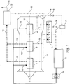
- Oil was stored in an oil tank 1 and pumped by means of an oil pump 5 in ventilated storage chambers 2, 3 and an unvented storage chamber 4. This is done via at least one supply line 10. Furthermore, a return pump unit 6 is provided, which is mechanically driven and discharges oil from the storage chambers 2, 3 and 4 via return lines 11 into the oil tank 1.
- the Fig. 1 further shows a breather 13, which is connected via a vent line 15 to the storage chambers 2, 3 and 4, to remove air and remove oil.
- the Oil is returned via a return line 12 to the return pump unit 6, while the air is discharged via an external vent line 14.
- the Fig. 1 shows a machine axis 16.
- At least one electric return pump 7 is provided, which is connected via a return line 8 with at least the non-ventilated storage chamber 4.
- a shut-off device 9 is provided, which is mechanically or electrically actuated.
- FIG. 1 a return line 17, which is provided with a mechanical shut-off device 18 (mechanically or electrically actuated) to remove oil at a standstill of the mechanical return pump unit 6 from the storage chambers 2, 3 and 4.
- a mechanical shut-off device 18 mechanically or electrically actuated
Landscapes
- Engineering & Computer Science (AREA)
- General Engineering & Computer Science (AREA)
- Mechanical Engineering (AREA)
- Motor Or Generator Frames (AREA)
- Connection Of Motors, Electrical Generators, Mechanical Devices, And The Like (AREA)
- Lubrication Of Internal Combustion Engines (AREA)
Description
Die Erfindung bezieht sich auf ein Gasturbinenlagerölsystem gemäß dem Oberbegriff des Anspruches 1.The invention relates to a gas turbine bearing oil system according to the preamble of
Im Einzelnen bezieht sich die Erfindung auf ein Ölsystem, bei welchem Öl von Lagerkammern einer Gasturbine mittels einer Rückführpumpeneinheit in einen Öltank zurückgeführt wird.In detail, the invention relates to an oil system in which oil is returned from storage chambers of a gas turbine by means of a return pump unit in an oil tank.
Ein derartiges Ölsystem ist beispielsweise aus der
Vorbekannte Ölrückführsysteme von Lagerkammern von Gasturbinen verwenden zumindest eine Rückführpumpeneinheit. Dabei ist jede Lagerkammer mit einer eigenen Rückführpumpe verbunden. Die einzelnen Rückführpumpen werden über eine gemeinsame Antriebswelle angetrieben. Dabei ist die Ölpumpe zum Zuführen des Öls üblicherweise ebenfalls Teil der Rückführpumpeneinheit und wird mit dieser über die gleiche Antriebswelle angetrieben. Alle Pumpen werden somit durch eine oder zwei Antriebswellen mechanisch mit der Hochdruckwelle der Gasturbine über eine Getriebeeinheit verbunden. Dies bedeutet, dass beim Abschalten oder Herunterfahren der Gasturbine auch die Pumpen nicht mehr angetrieben werden.Previous oil return systems of storage chambers of gas turbines use at least one return pump unit. Each storage chamber is connected to its own return pump. The individual return pumps are driven by a common drive shaft. In this case, the oil pump for supplying the oil is usually also part of the return pump unit and is driven with this on the same drive shaft. All pumps are thus mechanically connected by one or two drive shafts with the high-pressure shaft of the gas turbine via a gear unit. This means that when switching off or shutdown of the gas turbine and the pumps are no longer driven.
Beim Abschalten der Gasturbine oder beim Stillstand der Gasturbine können somit Ölleckagen aus den Lagerkammern über die Luftdichtungen auftreten, wenn der Lager-Luftdruck absinkt und der Druck in der Lagerkammer somit auf einen niedrigeren Wert absinkt.When switching off the gas turbine or at standstill of the gas turbine thus oil leakage from the storage chambers on the air seals can occur when the bearing air pressure drops and thus the pressure in the storage chamber drops to a lower value.
Die
Die
Der Erfindung liegt die Aufgabe zugrunde, ein Gasturbinenlagerölsystem der eingangs genannten Art zu schaffen, welches bei einfachem Aufbau und einfacher, kostengünstiger Herstellbarkeit ein hohes Maß an Betriebssicherheit aufweist und Ölleckagen beim stillstehender Gasturbine oder beim Herunterfahren der Gasturbine vermeidet. Erfindungsgemäß wird die Aufgabe durch die Merkmalskombinationen des Anspruchs 1 gelöst, die Unteransprüche zeigen weitere vorteilhafte Ausgestaltungen der Erfindung.The invention has for its object to provide a gas turbine bearing oil system of the type mentioned, which with a simple structure and simple, inexpensive to manufacture a high degree Has operational reliability and avoids oil leaks in the stationary gas turbine or shutting down the gas turbine. According to the invention the object is achieved by the combination of features of
Erfindungsgemäß ist somit vorgesehen, eine zusätzliche elektrische Rückführpumpe zur Rückführung von Öl aus zumindest einer der Lagerkammern zu dem Öltank vorzusehen.According to the invention is thus provided to provide an additional electric return pump for returning oil from at least one of the storage chambers to the oil tank.
Durch die erfindungsgemäße Ausgestaltung wird erreicht, dass die Rückführkapazität für Öl aus der Lagerkammer auch dann aufrecht erhalten wird, wenn die Gasturbine heruntergefahren wird oder abgeschaltet ist. Somit wird erfindungsgemäß sämtliches Öl aus der Lagerkammer zurückgeführt, so dass Ölleckagen nicht auftreten, da die Wahrscheinlichkeit, dass Öl durch die Luftströmung der Dichtung bei einer Strömungsumkehr der Lagerluft ausgespült wird, reduziert wird.The embodiment according to the invention ensures that the return capacity for oil from the storage chamber is maintained even when the gas turbine is shut down or switched off. Thus, according to the invention, all the oil is returned from the storage chamber so that oil leaks do not occur, since the likelihood of oil being flushed out by the air flow of the gasket upon flow reversal of the storage air is reduced.
Weiterhin wird durch die Vermeidung einer Strömungsumkehr eine Druckumkehr innerhalb der Lagerkammer durch ausströmendes Öl vermieden. Auch dies erweist sich als vorteilhaft.Furthermore, by avoiding a flow reversal, a pressure reversal within the storage chamber is avoided by escaping oil. Again, this proves to be beneficial.
Die Erfindung ist nicht nur für unbelüftete Lagerkammern anwendbar, sondern kann auch bei belüfteten Lagerkammern vorgesehen sein.The invention is not only applicable to unvented storage chambers, but may also be provided in ventilated storage chambers.
Erfindungsgemäß ist somit eine zusätzliche elektrische Rückführpumpe vorgesehen, die auch gering dimensioniert sein kann und die separat angeordnet ist. Die elektrische erfindungsgemäß vorgesehene zusätzliche Rückführpumpe wird bevorzugterweise bei einem Abschalten oder Herunterfahren der Gasturbine aktiviert und führt dann die Ölrückführung (das Abpumpen des Öls) unabhängig davon durch, ob sich die Hochdruckwelle der Turbine noch dreht oder nicht.According to the invention, an additional electric return pump is thus provided, which can also be dimensioned small and which is arranged separately. The electrical inventively provided additional return pump is preferably activated at a shutdown or shutdown of the gas turbine and then performs the oil return (the pumping of the oil) regardless of whether the high pressure shaft of the turbine is still rotating or not.
Erfindungsgemäß ist es möglich, die elektrische Rückführpumpe (oder die mehreren elektrischen Rückführpumpen) jeweils in einem Bypass vorzusehen, der die mechanischen Pumpen der Pumpenrückführeinheit umgeht.According to the invention, it is possible to provide the electric return pump (or the several electric return pumps) in each case in a bypass which bypasses the mechanical pumps of the pump return unit.
Besonders günstig ist es, dass erfindungsgemäß ein derartiger Bypass durch ein Absperrelement oder ein Ventil geschlossen wird, solange die Gasturbine läuft und die mechanische Rückführpumpeneinheit in Betrieb ist. Hierdurch werden Leckagen durch die elektrische Rückführpumpe beim Betrieb der mechanischen Rückführpumpeneinheit vermieden.It is particularly advantageous that according to the invention such a bypass is closed by a shut-off element or a valve, as long as the gas turbine is running and the mechanical return pump unit is in operation. As a result, leaks are avoided by the electric return pump during operation of the mechanical return pump unit.
Das Absperrelement/Absperrorgan/Ventil kann beispielsweise mechanisch betätigt werden. Dies kann durch eine Druckdifferenz zwischen einer Druckquelle für die Lagerluft und einer anderen Druckquelle von der Lagerkammer erfolgen. Dabei wird der zur Verfügung stehende Druck während des Betriebs der Gasturbine in vorteilhafter Weise ausgenutzt.The shut-off / shut-off valve / valve can be mechanically operated, for example. This can be done by a pressure difference between a pressure source for the bearing air and another pressure source from the storage chamber. In this case, the available pressure during operation of the gas turbine is advantageously utilized.
Eine weitere Möglichkeit der mechanischen Betätigung des Absperrorgans besteht darin, den Öldruck in der Zuführleitung des Öls von der mechanischen Ölpumpe zu den Lagerkammern zu verwenden, um das Absperrorgan bei laufender Gasturbine zu schließen. Bei einem Abschalten oder Herunterfahren der Gasturbine erfolgt somit ein Druckabfall oder eine negative Druckdifferenz, die das Absperrorgan betätigen kann.Another way of mechanically actuating the obturator is to use the oil pressure in the supply line of the oil from the mechanical oil pump to the storage chambers to close the obturator while the gas turbine is running. When switching off or shutdown of the gas turbine thus takes place a pressure drop or a negative pressure difference, which can operate the shut-off.
Die erfindungsgemäße, zumindest eine elektrische zusätzliche Rückführpumpe kann durch elektrische Energie angetrieben werden, die von einem zusätzlichen Generator, von einerThe inventive, at least one electric additional return pump can be driven by electrical energy from an additional generator, from a
Hilfsenergieeinheit (APU) oder von einem IDG zugeführt wird. Es ist jedoch in besonders vorteilhafter Weise auch möglich, eine zusätzliche elektrische Energiespeicherung (Batterie) vorzusehen, da die elektrische Rückführpumpe nur für einen begrenzten Zeitraum betrieben werden muss, um beim Herunterfahren oder Beginn des Stillstands der Gasturbine das restliche Öl aus den Lagerkammern abzuführen. Insofern ist keine große Energiemenge zu speichern.Auxiliary power unit (APU) or supplied by an IDG. However, it is also possible in a particularly advantageous manner, to provide an additional electrical energy storage (battery), since the electric return pump must be operated only for a limited period of time to dissipate the remaining oil from the storage chambers when shutting down or start the stoppage of the gas turbine. In this respect, no large amount of energy is to be stored.
Erfindungsgemäß ist es somit vorteilhaft, dass das Öl aus den Lagerkammern über eine zumindest begrenzte, minimale Zeitdauer auch dann abgeführt werden und sich entsprechend ein Druckabbau in dem Ölsystem einstellt, wenn die Gasturbine abgeschaltet wird oder zum Stillstand kommt. Eine Druckumkehr in den Lagerkammern wird somit verhindert. Weiterhin wird die Gefahr von Ölleckagen vermieden, wodurch sich insgesamt ein verringerter Ölverbrauch ergibt.According to the invention, it is thus advantageous for the oil to be discharged from the storage chambers over an at least limited, minimum period of time, and accordingly a pressure reduction in the oil system to be established when the gas turbine is switched off or comes to a standstill. A pressure reversal in the storage chambers is thus prevented. Furthermore, the risk of oil leakage is avoided, resulting in a total reduced oil consumption.
Im Folgenden wird die Erfindung anhand eines Ausführungsbeispiels in Verbindung mit der Zeichnung beschrieben. Dabei zeigt:
- Fig. 1
- eine schematische Darstellung eines Gasturbinenöllagersystems.
- Fig. 1
- a schematic representation of a gas turbine oil storage system.
Öl wurde in einem Öltank 1 bevorratet und mittels einer Ölpumpe 5 in belüftete Lagerkammern 2, 3 und eine unbelüftete Lagerkammer 4 gepumpt. Dies erfolgt über zumindest eine Zuführleitung 10. Weiterhin ist eine Rückführpumpeneinheit 6 vorgesehen, die mechanisch angetrieben wird und Öl aus den Lagerkammern 2, 3 und 4 über Rückführleitungen 11 in den Öltank 1 abführt.Oil was stored in an
Die
Die
Erfindungsgemäß ist zumindest eine elektrische Rückführpumpe 7 vorgesehen, die über eine Rückführleitung 8 mit zumindest der unbelüfteten Lagerkammer 4 verbunden ist. In der Rückführleitung 8 ist ein Absperrorgan 9 vorgesehen, welches mechanisch oder elektrisch betätigbar ist.According to the invention, at least one
Weiterhin zeigt die
- 11
- Öltankoil tank
- 22
- Belüftete LagerkammerVentilated storage chamber
- 33
- Belüftete LagerkammerVentilated storage chamber
- 44
- Unbelüftete LagerkammerUnvented storage chamber
- 55
- Ölpumpeoil pump
- 66
- RückführpumpeneinheitRecirculation pump unit
- 77
- Elektrische RückführpumpeElectric return pump
- 88th
- RückführleitungReturn line
- 99
- Absperrorganshutoff
- 1010
- Zuführleitungfeed
- 1111
- RückführleitungReturn line
- 1212
- RückführleitungReturn line
- 1313
- Entlüfter (breather)Deaerator (breather)
- 1414
- Externe EntlüftungsleitungExternal vent line
- 1515
- Entlüftungsleitungvent line
- 1616
- Maschinenachsemachine axis
- 1717
- RückführleitungReturn line
- 1818
- Absperrorganshutoff
Claims (6)
- Gas-turbine bearing oil system with an oil supply including at least one oil pump (5) supplying oil from an oil tank (1) to the bearing chambers (2, 3, 4) and at least one recirculation pump unit (6) for the return of oil from the bearing chambers (2, 3, 4) to the oil tank (1), characterized by at least one additional electric recirculation pump (7) for the return of oil from at least one bearing chamber (2, 3, 4) to the oil tank (1), wherein the electric recirculation pump (7) is separately arranged from the recirculation pump unit (6), wherein the recirculation pump (7) is operationally connected via a separate return line (8), wherein the separate return line (8) is provided with a shut-off device (9).
- System in accordance with Claim 1, characterized in that the electric recirculation pump (7) is actuatable when the gas turbine is out of operation.
- System in accordance with Claim 1 or 2, characterized in that the shut-off device (9) is mechanically actuatable by pressure differences between the bearing air and the internal pressure of the bearing chamber.
- System in accordance with Claim 1 or 2, characterized in that the shut-off device (9) is actuatable by an oil pressure in the system when the turbine is in operation.
- System in accordance with one of the Claims 1 to 4, characterized in that the electric recirculation pump (7) is supplied with electric power via a gas-turbine power supply.
- System in accordance with one of the Claims 1 to 4, characterized in that the recirculation pump (7) is supplied with electric power via a separate battery.
Applications Claiming Priority (1)
| Application Number | Priority Date | Filing Date | Title |
|---|---|---|---|
| DE102008009822A DE102008009822A1 (en) | 2008-02-19 | 2008-02-19 | Gas turbine bearing oil system with improved oil return |
Publications (3)
| Publication Number | Publication Date |
|---|---|
| EP2093386A2 EP2093386A2 (en) | 2009-08-26 |
| EP2093386A3 EP2093386A3 (en) | 2011-06-01 |
| EP2093386B1 true EP2093386B1 (en) | 2018-08-29 |
Family
ID=40601230
Family Applications (1)
| Application Number | Title | Priority Date | Filing Date |
|---|---|---|---|
| EP09002145.2A Active EP2093386B1 (en) | 2008-02-19 | 2009-02-16 | Gas turbine bearing oil system with oil recirculation |
Country Status (3)
| Country | Link |
|---|---|
| US (1) | US8281563B2 (en) |
| EP (1) | EP2093386B1 (en) |
| DE (1) | DE102008009822A1 (en) |
Families Citing this family (7)
| Publication number | Priority date | Publication date | Assignee | Title |
|---|---|---|---|---|
| GB201109799D0 (en) * | 2011-06-13 | 2011-07-27 | Rolls Royce Plc | A bearing chamber apparatus |
| US9140194B2 (en) | 2012-01-11 | 2015-09-22 | Honeywell International Inc. | Gas turbine engine starter-generator with integrated lube oil scavenge functionality |
| FR3011277B1 (en) * | 2013-09-30 | 2018-04-06 | Turbomeca | TURBOMACHINE ADAPTED TO OPERATE IN VIREUR MODE |
| EP3056790B1 (en) * | 2015-02-11 | 2019-04-03 | O.M.C.A. di Bassi Giovanni | Lubricating central unit for lubricating mechanical systems |
| US10851941B2 (en) * | 2017-12-04 | 2020-12-01 | Rolls-Royce Corporation | Lubrication and scavenge system |
| GB201900906D0 (en) * | 2019-01-23 | 2019-03-13 | Rolls Royce Plc | Oil scavenge system |
| CN112594016A (en) * | 2020-12-02 | 2021-04-02 | 山东齐鲁电机制造有限公司 | Integral oil station for turbine lubricating oil |
Family Cites Families (25)
| Publication number | Priority date | Publication date | Assignee | Title |
|---|---|---|---|---|
| GB509238A (en) | 1937-10-12 | 1939-07-12 | Neil Shaw Muir | Improvements in means for heating liquids, for use in the operation of aircraft and for other purposes |
| US2402467A (en) * | 1944-01-31 | 1946-06-18 | Westinghouse Electric Corp | Lubrication control |
| US3451214A (en) * | 1967-03-15 | 1969-06-24 | Garrett Corp | Cold engine start facilitating apparatus |
| FR1594316A (en) * | 1968-11-28 | 1970-06-01 | ||
| US3769790A (en) * | 1972-03-20 | 1973-11-06 | Gen Motors Corp | Gas turbine lubrication |
| FR2358615A1 (en) * | 1976-07-16 | 1978-02-10 | Snecma | Lubricating oil recovery system for aero engine - has auxiliary oil recovery pump driven by hydraulic motor using parts of feed oil for use if main recovery pump fails |
| US4284174A (en) | 1979-04-18 | 1981-08-18 | Avco Corporation | Emergency oil/mist system |
| DE2940643A1 (en) * | 1979-10-06 | 1981-04-16 | Klöckner-Humboldt-Deutz AG, 5000 Köln | FACILITIES FOR THE HEATING MACHINES |
| US4441311A (en) * | 1982-05-13 | 1984-04-10 | United Technologies Corporation | Means for controlling the air scavenge pressure in the bearing compartment of a gas turbine engine |
| DE3242366C2 (en) * | 1982-11-16 | 1985-02-07 | MTU Motoren- und Turbinen-Union München GmbH, 8000 München | Oil supply device for gas turbine engines that can be suspended in any flight situation |
| JPH0667517B2 (en) | 1986-01-29 | 1994-08-31 | 株式会社荏原製作所 | Methane fermentation method of organic aqueous solution |
| DE3605619A1 (en) | 1986-02-21 | 1987-08-27 | Mtu Muenchen Gmbh | FLOWING MACHINE WITH SUPPLY DEVICE FOR LUBRICANTS |
| US4940114A (en) * | 1989-09-05 | 1990-07-10 | Albrecht Kenneth D | Engine prelubricating system |
| GB2260577B (en) * | 1991-10-16 | 1994-10-05 | Rolls Royce Plc | Gas turbine engine starting |
| DE4304482A1 (en) * | 1993-02-15 | 1994-08-18 | Abb Management Ag | Lubrication system for a turbo-engine |
| US7426834B2 (en) | 2004-02-03 | 2008-09-23 | General Electric Company | “Get home” oil supply and scavenge system |
| DE102005031804A1 (en) * | 2005-07-07 | 2007-01-18 | Mtu Aero Engines Gmbh | lubricant system |
| US7571597B2 (en) * | 2006-01-25 | 2009-08-11 | Honeywell International Inc. | Airframe mounted motor driven lubrication pump control system and method |
| US7836675B2 (en) | 2006-02-21 | 2010-11-23 | General Electric Company | Supercore sump vent pressure control |
| US7451753B2 (en) | 2006-04-21 | 2008-11-18 | Pratt & Whitney Canada Corp. | Pre-heating of a liquid in an aircraft reservoir |
| DE102006023580A1 (en) * | 2006-05-19 | 2007-11-22 | Mtu Aero Engines Gmbh | Lubricant system for gas turbine aircraft engine, has ejector-device, where part of lubricant flow stream removed from tank is supplied to ejector device, and low pressure arises in tank for return flow of lubricant from load into tank |
| US7543695B2 (en) * | 2006-07-21 | 2009-06-09 | Gm Global Technology Operations, Inc. | Hydraulic system for an electro-mechanical transmission and method of providing fluid to transmission components |
| FR2912777B1 (en) * | 2007-02-21 | 2009-05-01 | Snecma Sa | DEVICE AND METHOD FOR EMERGENCY LUBRICATION OF MOTOR. |
| US8113317B2 (en) * | 2007-07-06 | 2012-02-14 | Honeywell International Inc. | Electric motor driven lubrication pump control system and method that accomodates turbomachine windmill operation |
| US8181746B2 (en) * | 2008-09-18 | 2012-05-22 | United Technologies Corporation | Continuous supply fluid reservoir |
-
2008
- 2008-02-19 DE DE102008009822A patent/DE102008009822A1/en not_active Withdrawn
-
2009
- 2009-02-16 EP EP09002145.2A patent/EP2093386B1/en active Active
- 2009-02-19 US US12/379,378 patent/US8281563B2/en active Active
Non-Patent Citations (1)
| Title |
|---|
| None * |
Also Published As
| Publication number | Publication date |
|---|---|
| EP2093386A3 (en) | 2011-06-01 |
| EP2093386A2 (en) | 2009-08-26 |
| US8281563B2 (en) | 2012-10-09 |
| DE102008009822A1 (en) | 2009-08-20 |
| US20090235632A1 (en) | 2009-09-24 |
Similar Documents
| Publication | Publication Date | Title |
|---|---|---|
| EP2093386B1 (en) | Gas turbine bearing oil system with oil recirculation | |
| EP1917428B1 (en) | Method of operating a power plant which comprises a pressure storage vessel | |
| DE10213598B4 (en) | Oil pump for an internal combustion engine and method for operating the same | |
| EP1536996B1 (en) | Drive unit comprising a retarder | |
| EP2834542B1 (en) | Closed hydraulic circuit | |
| DE10124108A1 (en) | Start-up system for internal combustion engine builds up pressure in pipe systems for components and has supply module with drive independent of internal combustion engine | |
| DE102016216235A1 (en) | APPARATUS FOR WATER INJECTION IN A VEHICLE AND METHOD FOR OPERATING SUCH A DEVICE | |
| EP1948928A1 (en) | Compressor | |
| EP1624167B1 (en) | Controlled pressure system for vehicles of a cooling circuit, in which a retarder is placed | |
| DE102018213713A1 (en) | Fuel cell system and method for switching off a fuel cell system | |
| DE102007060218A1 (en) | Method for operating a compressor | |
| DE102006004092B3 (en) | Two-stroke large-diesel engine, has hydraulic power unit driven by drive unit that is operable with exhaust gas in upper output region, where hydraulic power unit composes pump and is assigned to common rail | |
| WO2020148010A1 (en) | Fuel cell system | |
| DE4026099C2 (en) | Oil supply system for the bearings of exhaust gas turbochargers that can be switched on and off | |
| DE102007051498A1 (en) | Fuel metering unit for an aircraft engine | |
| DE102014220389B4 (en) | Arrangement and method for using braking energy in a fuel system | |
| DE102013212937A1 (en) | Device for opening and closing guide vane of hydraulic machine e.g. water turbine, has two fixed displacement pumps driven by rotation speed-variable drive and operated on hydraulic cylinder over hydraulic system | |
| DE102017206172A1 (en) | Scroll expansion machine and exhaust residual heat utilization device, in particular a vehicle, with such an expansion machine | |
| DE102020200611A1 (en) | Fuel cell system | |
| WO2017084791A1 (en) | Providing a vacuum for ventilating tanks or for brake boosters | |
| DE487511C (en) | Device for switching a pump on and off during operation in hydraulic storage power plants | |
| EP3124761A1 (en) | Turbine installation | |
| DE3814368C1 (en) | System for supplying oil to a rotary piston compressor cooled by oil injection | |
| DE102018123431B3 (en) | Device for crushing piece goods and method for emergency switching off of the device | |
| EP1612426B1 (en) | Controlled, energy efficient multi stage centrifugal pump with high pressure stage |
Legal Events
| Date | Code | Title | Description |
|---|---|---|---|
| PUAI | Public reference made under article 153(3) epc to a published international application that has entered the european phase |
Free format text: ORIGINAL CODE: 0009012 |
|
| AK | Designated contracting states |
Kind code of ref document: A2 Designated state(s): AT BE BG CH CY CZ DE DK EE ES FI FR GB GR HR HU IE IS IT LI LT LU LV MC MK MT NL NO PL PT RO SE SI SK TR |
|
| AX | Request for extension of the european patent |
Extension state: AL BA RS |
|
| PUAL | Search report despatched |
Free format text: ORIGINAL CODE: 0009013 |
|
| AK | Designated contracting states |
Kind code of ref document: A3 Designated state(s): AT BE BG CH CY CZ DE DK EE ES FI FR GB GR HR HU IE IS IT LI LT LU LV MC MK MT NL NO PL PT RO SE SI SK TR |
|
| AX | Request for extension of the european patent |
Extension state: AL BA RS |
|
| RIC1 | Information provided on ipc code assigned before grant |
Ipc: F16N 7/40 20060101ALI20110427BHEP Ipc: F01D 25/20 20060101AFI20090528BHEP |
|
| 17P | Request for examination filed |
Effective date: 20110824 |
|
| AKX | Designation fees paid |
Designated state(s): DE FR GB |
|
| STAA | Information on the status of an ep patent application or granted ep patent |
Free format text: STATUS: EXAMINATION IS IN PROGRESS |
|
| 17Q | First examination report despatched |
Effective date: 20170127 |
|
| GRAP | Despatch of communication of intention to grant a patent |
Free format text: ORIGINAL CODE: EPIDOSNIGR1 |
|
| STAA | Information on the status of an ep patent application or granted ep patent |
Free format text: STATUS: GRANT OF PATENT IS INTENDED |
|
| INTG | Intention to grant announced |
Effective date: 20180315 |
|
| GRAS | Grant fee paid |
Free format text: ORIGINAL CODE: EPIDOSNIGR3 |
|
| GRAA | (expected) grant |
Free format text: ORIGINAL CODE: 0009210 |
|
| STAA | Information on the status of an ep patent application or granted ep patent |
Free format text: STATUS: THE PATENT HAS BEEN GRANTED |
|
| AK | Designated contracting states |
Kind code of ref document: B1 Designated state(s): DE FR GB |
|
| REG | Reference to a national code |
Ref country code: GB Ref legal event code: FG4D Free format text: NOT ENGLISH |
|
| REG | Reference to a national code |
Ref country code: DE Ref legal event code: R096 Ref document number: 502009015224 Country of ref document: DE |
|
| REG | Reference to a national code |
Ref country code: DE Ref legal event code: R026 Ref document number: 502009015224 Country of ref document: DE |
|
| PLBI | Opposition filed |
Free format text: ORIGINAL CODE: 0009260 |
|
| 26 | Opposition filed |
Opponent name: UNITED TECHNOLOGIES CORPORATION Effective date: 20190404 |
|
| PLAX | Notice of opposition and request to file observation + time limit sent |
Free format text: ORIGINAL CODE: EPIDOSNOBS2 |
|
| PLBB | Reply of patent proprietor to notice(s) of opposition received |
Free format text: ORIGINAL CODE: EPIDOSNOBS3 |
|
| PLAB | Opposition data, opponent's data or that of the opponent's representative modified |
Free format text: ORIGINAL CODE: 0009299OPPO |
|
| R26 | Opposition filed (corrected) |
Opponent name: RAYTHEON TECHNOLOGIES CORPORATION Effective date: 20190404 |
|
| REG | Reference to a national code |
Ref country code: DE Ref legal event code: R100 Ref document number: 502009015224 Country of ref document: DE |
|
| PGFP | Annual fee paid to national office [announced via postgrant information from national office to epo] |
Ref country code: GB Payment date: 20210223 Year of fee payment: 13 |
|
| PLCK | Communication despatched that opposition was rejected |
Free format text: ORIGINAL CODE: EPIDOSNREJ1 |
|
| PLBN | Opposition rejected |
Free format text: ORIGINAL CODE: 0009273 |
|
| STAA | Information on the status of an ep patent application or granted ep patent |
Free format text: STATUS: OPPOSITION REJECTED |
|
| 27O | Opposition rejected |
Effective date: 20200930 |
|
| GBPC | Gb: european patent ceased through non-payment of renewal fee |
Effective date: 20220216 |
|
| PG25 | Lapsed in a contracting state [announced via postgrant information from national office to epo] |
Ref country code: GB Free format text: LAPSE BECAUSE OF NON-PAYMENT OF DUE FEES Effective date: 20220216 |
|
| P01 | Opt-out of the competence of the unified patent court (upc) registered |
Effective date: 20230528 |
|
| PGFP | Annual fee paid to national office [announced via postgrant information from national office to epo] |
Ref country code: DE Payment date: 20240228 Year of fee payment: 16 |
|
| PGFP | Annual fee paid to national office [announced via postgrant information from national office to epo] |
Ref country code: FR Payment date: 20240226 Year of fee payment: 16 |