DE102008009822A1 - Gas turbine bearing oil system with improved oil return - Google Patents
Gas turbine bearing oil system with improved oil return Download PDFInfo
- Publication number
- DE102008009822A1 DE102008009822A1 DE102008009822A DE102008009822A DE102008009822A1 DE 102008009822 A1 DE102008009822 A1 DE 102008009822A1 DE 102008009822 A DE102008009822 A DE 102008009822A DE 102008009822 A DE102008009822 A DE 102008009822A DE 102008009822 A1 DE102008009822 A1 DE 102008009822A1
- Authority
- DE
- Germany
- Prior art keywords
- oil
- return pump
- gas turbine
- return
- pump
- Prior art date
- Legal status (The legal status is an assumption and is not a legal conclusion. Google has not performed a legal analysis and makes no representation as to the accuracy of the status listed.)
- Withdrawn
Links
- 230000001737 promoting effect Effects 0.000 abstract 1
- 239000003921 oil Substances 0.000 description 38
- BUHVIAUBTBOHAG-FOYDDCNASA-N (2r,3r,4s,5r)-2-[6-[[2-(3,5-dimethoxyphenyl)-2-(2-methylphenyl)ethyl]amino]purin-9-yl]-5-(hydroxymethyl)oxolane-3,4-diol Chemical compound COC1=CC(OC)=CC(C(CNC=2C=3N=CN(C=3N=CN=2)[C@H]2[C@@H]([C@H](O)[C@@H](CO)O2)O)C=2C(=CC=CC=2)C)=C1 BUHVIAUBTBOHAG-FOYDDCNASA-N 0.000 description 1
- 230000009286 beneficial effect Effects 0.000 description 1
- 238000004146 energy storage Methods 0.000 description 1
- 230000002349 favourable effect Effects 0.000 description 1
- 238000005086 pumping Methods 0.000 description 1
- 238000009987 spinning Methods 0.000 description 1
- 239000010723 turbine oil Substances 0.000 description 1
Classifications
-
- F—MECHANICAL ENGINEERING; LIGHTING; HEATING; WEAPONS; BLASTING
- F01—MACHINES OR ENGINES IN GENERAL; ENGINE PLANTS IN GENERAL; STEAM ENGINES
- F01D—NON-POSITIVE DISPLACEMENT MACHINES OR ENGINES, e.g. STEAM TURBINES
- F01D25/00—Component parts, details, or accessories, not provided for in, or of interest apart from, other groups
- F01D25/18—Lubricating arrangements
- F01D25/20—Lubricating arrangements using lubrication pumps
-
- F—MECHANICAL ENGINEERING; LIGHTING; HEATING; WEAPONS; BLASTING
- F16—ENGINEERING ELEMENTS AND UNITS; GENERAL MEASURES FOR PRODUCING AND MAINTAINING EFFECTIVE FUNCTIONING OF MACHINES OR INSTALLATIONS; THERMAL INSULATION IN GENERAL
- F16N—LUBRICATING
- F16N7/00—Arrangements for supplying oil or unspecified lubricant from a stationary reservoir or the equivalent in or on the machine or member to be lubricated
- F16N7/38—Arrangements for supplying oil or unspecified lubricant from a stationary reservoir or the equivalent in or on the machine or member to be lubricated with a separate pump; Central lubrication systems
- F16N7/40—Arrangements for supplying oil or unspecified lubricant from a stationary reservoir or the equivalent in or on the machine or member to be lubricated with a separate pump; Central lubrication systems in a closed circulation system
-
- F—MECHANICAL ENGINEERING; LIGHTING; HEATING; WEAPONS; BLASTING
- F01—MACHINES OR ENGINES IN GENERAL; ENGINE PLANTS IN GENERAL; STEAM ENGINES
- F01M—LUBRICATING OF MACHINES OR ENGINES IN GENERAL; LUBRICATING INTERNAL COMBUSTION ENGINES; CRANKCASE VENTILATING
- F01M1/00—Pressure lubrication
- F01M1/12—Closed-circuit lubricating systems not provided for in groups F01M1/02 - F01M1/10
- F01M2001/123—Closed-circuit lubricating systems not provided for in groups F01M1/02 - F01M1/10 using two or more pumps
-
- F—MECHANICAL ENGINEERING; LIGHTING; HEATING; WEAPONS; BLASTING
- F16—ENGINEERING ELEMENTS AND UNITS; GENERAL MEASURES FOR PRODUCING AND MAINTAINING EFFECTIVE FUNCTIONING OF MACHINES OR INSTALLATIONS; THERMAL INSULATION IN GENERAL
- F16N—LUBRICATING
- F16N2210/00—Applications
- F16N2210/02—Turbines
-
- F—MECHANICAL ENGINEERING; LIGHTING; HEATING; WEAPONS; BLASTING
- F16—ENGINEERING ELEMENTS AND UNITS; GENERAL MEASURES FOR PRODUCING AND MAINTAINING EFFECTIVE FUNCTIONING OF MACHINES OR INSTALLATIONS; THERMAL INSULATION IN GENERAL
- F16N—LUBRICATING
- F16N2260/00—Fail safe
Landscapes
- Engineering & Computer Science (AREA)
- General Engineering & Computer Science (AREA)
- Mechanical Engineering (AREA)
- Motor Or Generator Frames (AREA)
- Connection Of Motors, Electrical Generators, Mechanical Devices, And The Like (AREA)
- Lubrication Of Internal Combustion Engines (AREA)
Abstract
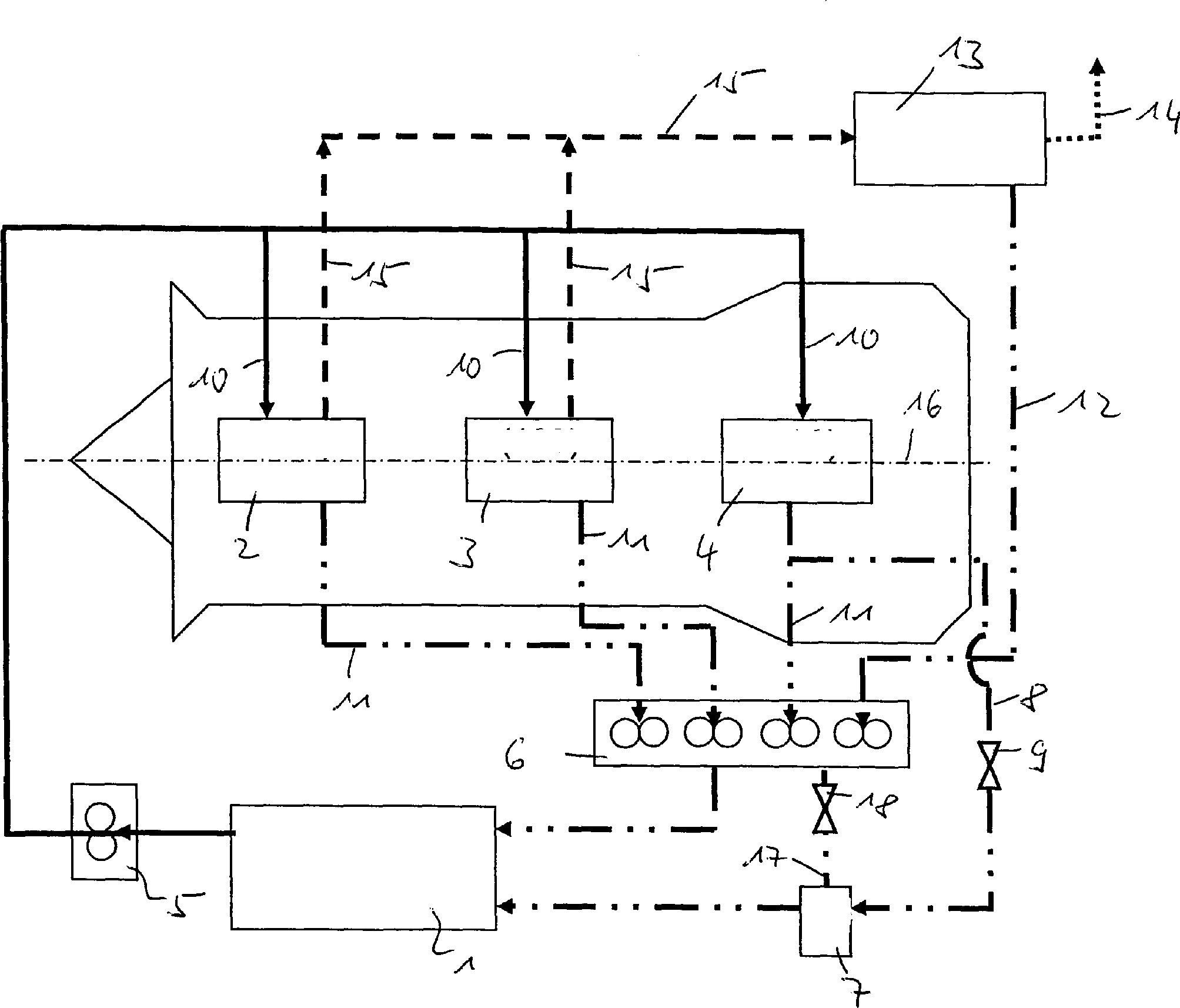
Die Erfindung bezieht sich auf ein Gasturbinenlagerölsystem mit einer Ölversorgung mit zumindest einer Öl aus dem Öltank 1 zu Lagerkammern 2, 3, 4 fördernden Ölpumpe 5 sowie zumindest einer Rückführpumpeneinheit 6 zur Rückführung von Öl aus den Lagerkammern 2, 3, 4 zu dem Öltank 1, gekennzeichnet durch zumindest eine zusätzliche elektrische Rückführpumpe 7 zur Rückführung von Öl aus zumindest einer Lagerkammer 2, 3, 4 zu dem Öltank 1.The invention relates to a gas turbine bearing oil system with an oil supply with at least one oil from the oil tank 1 to storage chambers 2, 3, 4 promotional oil pump 5 and at least one return pump unit 6 for returning oil from the storage chambers 2, 3, 4 to the oil tank 1, characterized by at least one additional electric return pump 7 for returning oil from at least one storage chamber 2, 3, 4 to the oil tank 1.
Description
Die Erfindung bezieht sich auf ein Gasturbinenlagerölsystem gemäß dem Oberbegriff des Anspruches 1.The The invention relates to a gas turbine bearing oil system according to the preamble of claim 1.
Im Einzelnen bezieht sich die Erfindung auf ein Ölsystem, bei welchem Öl von Lagerkammern einer Gasturbine mittels einer Rückführpumpeneinheit in einen Öltank zurückgeführt wird.in the In particular, the invention relates to an oil system, in which oil from storage chambers of a gas turbine by means of a return pump unit in an oil tank is returned.
Ein
derartiges Ölsystem ist beispielsweise aus der
Vorbekannte Ölrückführsysteme von Lagerkammern von Gasturbinen verwenden zumindest eine Rückführpumpeneinheit. Dabei ist jede Lagerkammer mit einer eigenen Rückführpumpe verbunden. Die einzelnen Rückführpumpen werden über eine gemeinsame Antriebswelle angetrieben. Dabei ist die Ölpumpe zum Zuführen des Öls üblicherweise ebenfalls Teil der Rückführpumpeneinheit und wird mit dieser über die gleiche Antriebswelle angetrieben. Alle Pumpen werden somit durch eine oder zwei Antriebswellen mechanisch mit der Hochdruckwelle der Gasturbine über eine Getriebeeinheit verbunden. Dies bedeutet, dass beim Abschalten oder Herunterfahren der Gasturbine auch die Pumpen nicht mehr angetrieben werden.Previous oil return systems of storage chambers of gas turbines use at least one return pump unit. Each storage chamber is equipped with its own return pump connected. The individual return pumps are connected via a driven common drive shaft. Here is the oil pump for supplying the oil usually also Part of the return pump unit and is over with this driven the same drive shaft. All pumps are thus mechanically by one or two drive shafts with the high pressure shaft of Gas turbine connected via a gear unit. This means, that when switching off or shutdown of the gas turbine and the Pumps are no longer driven.
Beim Abschalten der Gasturbine oder beim Stillstand der Gasturbine können somit Ölleckagen aus den Lagerkammern über die Luftdichtungen auftreten, wenn der Lager-Luftdruck absinkt und der Druck in der Lagerkammer somit auf einen niedrigeren Wert absinkt.At the Shut down the gas turbine or at standstill of the gas turbine can thus oil leakage from the storage chambers on the Air seals occur when the bearing air pressure drops and the pressure drops in the storage chamber thus drops to a lower value.
Der Erfindung liegt die Aufgabe zugrunde, ein Gasturbinenlagerölsystem der eingangs genannten Art zu schaffen, welches bei einfachem Aufbau und einfacher, kostengünstiger Herstellbarkeit ein hohes Maß an Betriebssicherheit aufweist und Ölleckagen beim stillstehender Gasturbine oder beim Herunterfahren der Gasturbine vermeidet.Of the Invention is based on the object, a gas turbine bearing oil system to create the type mentioned, which in a simple structure and simple, cost-effective manufacturability a high degree of operational safety and oil leaks at the stationary gas turbine or avoids shutdown of the gas turbine.
Erfindungsgemäß wird die Aufgabe durch die Merkmalskombinationen des Anspruchs 1 gelöst, die Unteransprüche zeigen weitere vorteilhafte Ausgestaltungen der Erfindung.According to the invention the problem solved by the combination of features of claim 1, the Subclaims show further advantageous embodiments the invention.
Erfindungsgemäß ist somit vorgesehen, eine zusätzliche elektrische Rückführpumpe zur Rückführung von Öl aus zumindest einer der Lagerkammern zu dem Öltank vorzusehen.According to the invention thus provided, an additional electric return pump for the return of oil from at least to provide one of the storage chambers to the oil tank.
Durch die erfindungsgemäße Ausgestaltung wird erreicht, dass die Rückführkapazität für Öl aus der Lagerkammer auch dann aufrecht erhalten wird, wenn die Gasturbine heruntergefahren wird oder abgeschaltet ist. Somit wird erfindungsgemäß sämtliches Öl aus der Lagerkammer zurückgeführt, so dass Ölleckagen nicht auftreten, da die Wahrscheinlichkeit, dass Öl durch die Luftströmung der Dichtung bei einer Strömungsumkehr der Lagerluft ausgespült wird, reduziert wird.By the embodiment according to the invention is achieved that the return capacity for oil from the storage chamber is maintained even when the gas turbine shut down or shut down. Thus, according to the invention all oil returned from the storage chamber, causing oil leakage Do not occur as the likelihood of getting oil through the air flow of the seal at a flow reversal the bearing air is flushed out, is reduced.
Weiterhin wird durch die Vermeidung einer Strömungsumkehr eine Druckumkehr innerhalb der Lagerkammer durch ausströmendes Öl vermieden. Auch dies erweist sich als vorteilhaft.Farther is a reversal of pressure by avoiding a flow reversal within the storage chamber due to escaping oil avoided. Again, this proves to be beneficial.
Die Erfindung ist nicht nur für unbelüftete Lagerkammern anwendbar, sondern kann auch bei belüfteten Lagerkammern vorgesehen sein.The Invention is not only for unvented storage chambers applicable, but can also be used in ventilated storage chambers be provided.
Erfindungsgemäß ist somit eine zusätzliche elektrische Rückführpumpe vorgesehen, die auch gering dimensioniert sein kann und die entweder separat angeordnet oder der Rückführpumpeneinheit mit den mehreren mechanischen Rückführpumpen zugeordnet sein kann.According to the invention thus an additional electric return pump provided, which may also be small in size and either arranged separately or the return pump unit with assigned to the multiple mechanical return pumps can be.
Die elektrische erfindungsgemäß vorgesehene zusätzliche Rückführpumpe wird bevorzugterweise bei einem Abschalten oder Herunterfahren der Gasturbine aktiviert und führt dann die Ölrückführung (das Abpumpen des Öls) unabhängig davon durch, ob sich die Hochdruckwelle der Turbine noch dreht oder nicht.The electrical according to the invention provided additional Return pump is preferably at a Shutdown or shutdown of the gas turbine is activated and leads then the oil return (the pumping of the oil) regardless of whether the high pressure shaft the turbine is still spinning or not.
Erfindungsgemäß ist es möglich, die elektrische Rückführpumpe (oder die mehreren elektrischen Rückführpumpen) jeweils in einem Bypass vorzusehen, der die mechanischen Pumpen der Pumpenrückführeinheit umgeht.According to the invention it possible, the electric return pump (or the several electric return pumps) each in a bypass to provide the mechanical pumps bypasses the pump return unit.
Besonders günstig ist es, wenn erfindungsgemäß ein derartiger Bypass durch ein Absperrelement oder ein Ventil geschlossen wird, solange die Gasturbine läuft und die mechanische Rückführpumpeneinheit in Betrieb ist. Hierdurch werden Leckagen durch die elektrische Rückführpumpe beim Betrieb der mechanischen Rückführpumpeneinheit vermieden.Especially It is favorable, if according to the invention a such bypass closed by a shut-off or a valve is as long as the gas turbine is running and the mechanical Return pump unit is in operation. hereby leaks are caused by the electric return pump during operation of the mechanical return pump unit avoided.
Das Absperrelement/Absperrorgan/Ventil kann beispielsweise mechanisch betätigt werden. Dies kann durch eine Druckdifferenz zwischen einer Druckquelle für die Lagerluft und einer anderen Druckquelle von der Lagerkammer erfolgen. Dabei wird der zur Verfügung stehende Druck während des Betriebs der Gasturbine in vorteilhafter Weise ausgenutzt.The Shut-off / shut-off / valve, for example, mechanically be operated. This can be due to a pressure difference between a pressure source for the bearing clearance and another pressure source from the storage chamber. It is the available standing pressure during operation of the gas turbine in an advantageous Exploited way.
Eine weitere Möglichkeit der mechanischen Betätigung des Absperrorgans besteht darin, den Öldruck in der Zuführleitung des Öls von der mechanischen Ölpumpe zu den Lagerkammern zu verwenden, um das Absperrorgan bei laufender Gasturbine zu schließen. Bei einem Abschalten oder Herunterfahren der Gasturbine erfolgt somit ein Druckabfall oder eine negative Druckdifferenz, die das Absperrorgan betätigen kann.Another way of mechanically actuating the obturator is to use the oil pressure in the supply line of the oil from the mechanical oil pump to the storage chambers to close the obturator while the gas turbine is running. At a shutdown or down drive the gas turbine thus takes place a pressure drop or a negative pressure difference, which can operate the shut-off.
Die erfindungsgemäße, zumindest eine elektrische zusätzliche Rückführpumpe kann durch elektrische Energie angetrieben werden, die von einem zusätzlichen Generator, von einer Hilfsenergieeinheit (APU) oder von einem IDG zugeführt wird. Es ist jedoch in besonders vorteilhafter Weise auch möglich, eine zusätzliche elektrische Energiespeicherung (Batterie) vorzusehen, da die elektrische Rückführpumpe nur für einen begrenzten Zeitraum betrieben werden muss, um beim Herunterfahren oder Beginn des Stillstands der Gasturbine das restliche Öl aus den Lagerkammern abzuführen. Insofern ist keine große Energiemenge zu speichern.The according to the invention, at least one electrical additional Return pump can be powered by electrical energy from an auxiliary generator, from an auxiliary power unit (APU) or supplied by an IDG. It is however in particular advantageously also possible, an additional provide electrical energy storage (battery), as the electric Return pump only for a limited amount Period must be operated to shut down or start the Standstill of the gas turbine the remaining oil from the storage chambers dissipate. In this respect, there is no large amount of energy save.
Erfindungsgemäß ist es somit vorteilhaft, dass das Öl aus den Lagerkammern über eine zumindest begrenzte, minimale Zeitdauer auch dann abgeführt werden und sich entsprechend ein Druckabbau in dem Ölsystem einstellt, wenn die Gasturbine abgeschaltet wird oder zum Stillstand kommt. Eine Druckumkehr in den Lagerkammern wird somit verhindert. Weiterhin wird die Gefahr von Ölleckagen vermieden, wodurch sich insgesamt ein verringerter Ölverbrauch ergibt.According to the invention It is thus advantageous that the oil from the storage chambers over an at least limited, minimum period of time then dissipated and accordingly a pressure reduction in the oil system adjusted when the gas turbine is shut down or comes to a standstill. A pressure reversal in the storage chambers is thus prevented. Farther avoids the risk of oil leakage, resulting in Overall, a reduced oil consumption results.
Im Folgenden wird die Erfindung anhand eines Ausführungsbeispiels in Verbindung mit der Zeichnung beschrieben. Dabei zeigt:in the The invention is based on an embodiment described in conjunction with the drawing. Showing:
Öl
wurde in einem Öltank
Die
Die
Erfindungsgemäß ist
zumindest eine elektrische Rückführpumpe
Weiterhin
zeigt die
- 11
- Öltankoil tank
- 22
- Belüftete Lagerkammerventilated storage chamber
- 33
- Belüftete Lagerkammerventilated storage chamber
- 44
- Unbelüftete Lagerkammerunventilated storage chamber
- 55
- Ölpumpeoil pump
- 66
- RückführpumpeneinheitRecirculation pump unit
- 77
- Elektrische Rückführpumpeelectrical Recirculation pump
- 88th
- RückführleitungReturn line
- 99
- Absperrorganshutoff
- 1010
- Zuführleitungfeed
- 1111
- RückführleitungReturn line
- 1212
- RückführleitungReturn line
- 1313
- Entlüfter (breather)ventilator (Breather)
- 1414
- Externe Entlüftungsleitungexternal vent line
- 1515
- Entlüftungsleitungvent line
- 1616
- Maschinenachsemachine axis
- 1717
- RückführleitungReturn line
- 1818
- Absperrorganshutoff
ZITATE ENTHALTEN IN DER BESCHREIBUNGQUOTES INCLUDE IN THE DESCRIPTION
Diese Liste der vom Anmelder aufgeführten Dokumente wurde automatisiert erzeugt und ist ausschließlich zur besseren Information des Lesers aufgenommen. Die Liste ist nicht Bestandteil der deutschen Patent- bzw. Gebrauchsmusteranmeldung. Das DPMA übernimmt keinerlei Haftung für etwaige Fehler oder Auslassungen.This list The documents listed by the applicant have been automated generated and is solely for better information recorded by the reader. The list is not part of the German Patent or utility model application. The DPMA takes over no liability for any errors or omissions.
Zitierte PatentliteraturCited patent literature
- - EP 1561908 A2 [0003] - EP 1561908 A2 [0003]
Claims (10)
Priority Applications (3)
| Application Number | Priority Date | Filing Date | Title |
|---|---|---|---|
| DE102008009822A DE102008009822A1 (en) | 2008-02-19 | 2008-02-19 | Gas turbine bearing oil system with improved oil return |
| EP09002145.2A EP2093386B1 (en) | 2008-02-19 | 2009-02-16 | Gas turbine bearing oil system with oil recirculation |
| US12/379,378 US8281563B2 (en) | 2008-02-19 | 2009-02-19 | Gas-turbine bearing oil system with improved oil return arrangement |
Applications Claiming Priority (1)
| Application Number | Priority Date | Filing Date | Title |
|---|---|---|---|
| DE102008009822A DE102008009822A1 (en) | 2008-02-19 | 2008-02-19 | Gas turbine bearing oil system with improved oil return |
Publications (1)
| Publication Number | Publication Date |
|---|---|
| DE102008009822A1 true DE102008009822A1 (en) | 2009-08-20 |
Family
ID=40601230
Family Applications (1)
| Application Number | Title | Priority Date | Filing Date |
|---|---|---|---|
| DE102008009822A Withdrawn DE102008009822A1 (en) | 2008-02-19 | 2008-02-19 | Gas turbine bearing oil system with improved oil return |
Country Status (3)
| Country | Link |
|---|---|
| US (1) | US8281563B2 (en) |
| EP (1) | EP2093386B1 (en) |
| DE (1) | DE102008009822A1 (en) |
Cited By (1)
| Publication number | Priority date | Publication date | Assignee | Title |
|---|---|---|---|---|
| CN112594016A (en) * | 2020-12-02 | 2021-04-02 | 山东齐鲁电机制造有限公司 | Integral oil station for turbine lubricating oil |
Families Citing this family (7)
| Publication number | Priority date | Publication date | Assignee | Title |
|---|---|---|---|---|
| GB201109799D0 (en) * | 2011-06-13 | 2011-07-27 | Rolls Royce Plc | A bearing chamber apparatus |
| US9140194B2 (en) | 2012-01-11 | 2015-09-22 | Honeywell International Inc. | Gas turbine engine starter-generator with integrated lube oil scavenge functionality |
| FR3011277B1 (en) * | 2013-09-30 | 2018-04-06 | Turbomeca | TURBOMACHINE ADAPTED TO OPERATE IN VIREUR MODE |
| EP3056790B1 (en) * | 2015-02-11 | 2019-04-03 | O.M.C.A. di Bassi Giovanni | Lubricating central unit for lubricating mechanical systems |
| US10851941B2 (en) * | 2017-12-04 | 2020-12-01 | Rolls-Royce Corporation | Lubrication and scavenge system |
| GB201900906D0 (en) * | 2019-01-23 | 2019-03-13 | Rolls Royce Plc | Oil scavenge system |
| US20260092560A1 (en) * | 2024-09-30 | 2026-04-02 | Rtx Corporation | Lubrication Circuit with Bearing Compartment Electric Pump in Scavenger Line |
Citations (5)
| Publication number | Priority date | Publication date | Assignee | Title |
|---|---|---|---|---|
| DE1958813A1 (en) * | 1968-11-28 | 1970-06-04 | Bennes Marrel Sa | Cooperating lubrication, control and regulation device for gas turbines |
| DE4304482A1 (en) * | 1993-02-15 | 1994-08-18 | Abb Management Ag | Lubrication system for a turbo-engine |
| EP1561908A2 (en) | 2004-02-03 | 2005-08-10 | General Electric Company | "Get Home" oil supply and scavenge system |
| DE102005031804A1 (en) * | 2005-07-07 | 2007-01-18 | Mtu Aero Engines Gmbh | lubricant system |
| DE102006023580A1 (en) * | 2006-05-19 | 2007-11-22 | Mtu Aero Engines Gmbh | Lubricant system for gas turbine aircraft engine, has ejector-device, where part of lubricant flow stream removed from tank is supplied to ejector device, and low pressure arises in tank for return flow of lubricant from load into tank |
Family Cites Families (20)
| Publication number | Priority date | Publication date | Assignee | Title |
|---|---|---|---|---|
| GB509238A (en) | 1937-10-12 | 1939-07-12 | Neil Shaw Muir | Improvements in means for heating liquids, for use in the operation of aircraft and for other purposes |
| US2402467A (en) * | 1944-01-31 | 1946-06-18 | Westinghouse Electric Corp | Lubrication control |
| US3451214A (en) * | 1967-03-15 | 1969-06-24 | Garrett Corp | Cold engine start facilitating apparatus |
| US3769790A (en) * | 1972-03-20 | 1973-11-06 | Gen Motors Corp | Gas turbine lubrication |
| FR2358615A1 (en) * | 1976-07-16 | 1978-02-10 | Snecma | Lubricating oil recovery system for aero engine - has auxiliary oil recovery pump driven by hydraulic motor using parts of feed oil for use if main recovery pump fails |
| US4284174A (en) | 1979-04-18 | 1981-08-18 | Avco Corporation | Emergency oil/mist system |
| DE2940643A1 (en) * | 1979-10-06 | 1981-04-16 | Klöckner-Humboldt-Deutz AG, 5000 Köln | FACILITIES FOR THE HEATING MACHINES |
| US4441311A (en) * | 1982-05-13 | 1984-04-10 | United Technologies Corporation | Means for controlling the air scavenge pressure in the bearing compartment of a gas turbine engine |
| DE3242366C2 (en) * | 1982-11-16 | 1985-02-07 | MTU Motoren- und Turbinen-Union München GmbH, 8000 München | Oil supply device for gas turbine engines that can be suspended in any flight situation |
| JPH0667517B2 (en) | 1986-01-29 | 1994-08-31 | 株式会社荏原製作所 | Methane fermentation method of organic aqueous solution |
| DE3605619A1 (en) | 1986-02-21 | 1987-08-27 | Mtu Muenchen Gmbh | FLOWING MACHINE WITH SUPPLY DEVICE FOR LUBRICANTS |
| US4940114A (en) * | 1989-09-05 | 1990-07-10 | Albrecht Kenneth D | Engine prelubricating system |
| GB2260577B (en) * | 1991-10-16 | 1994-10-05 | Rolls Royce Plc | Gas turbine engine starting |
| US7571597B2 (en) * | 2006-01-25 | 2009-08-11 | Honeywell International Inc. | Airframe mounted motor driven lubrication pump control system and method |
| US7836675B2 (en) | 2006-02-21 | 2010-11-23 | General Electric Company | Supercore sump vent pressure control |
| US7451753B2 (en) | 2006-04-21 | 2008-11-18 | Pratt & Whitney Canada Corp. | Pre-heating of a liquid in an aircraft reservoir |
| US7543695B2 (en) * | 2006-07-21 | 2009-06-09 | Gm Global Technology Operations, Inc. | Hydraulic system for an electro-mechanical transmission and method of providing fluid to transmission components |
| FR2912777B1 (en) * | 2007-02-21 | 2009-05-01 | Snecma Sa | DEVICE AND METHOD FOR EMERGENCY LUBRICATION OF MOTOR. |
| US8113317B2 (en) * | 2007-07-06 | 2012-02-14 | Honeywell International Inc. | Electric motor driven lubrication pump control system and method that accomodates turbomachine windmill operation |
| US8181746B2 (en) * | 2008-09-18 | 2012-05-22 | United Technologies Corporation | Continuous supply fluid reservoir |
-
2008
- 2008-02-19 DE DE102008009822A patent/DE102008009822A1/en not_active Withdrawn
-
2009
- 2009-02-16 EP EP09002145.2A patent/EP2093386B1/en active Active
- 2009-02-19 US US12/379,378 patent/US8281563B2/en active Active
Patent Citations (5)
| Publication number | Priority date | Publication date | Assignee | Title |
|---|---|---|---|---|
| DE1958813A1 (en) * | 1968-11-28 | 1970-06-04 | Bennes Marrel Sa | Cooperating lubrication, control and regulation device for gas turbines |
| DE4304482A1 (en) * | 1993-02-15 | 1994-08-18 | Abb Management Ag | Lubrication system for a turbo-engine |
| EP1561908A2 (en) | 2004-02-03 | 2005-08-10 | General Electric Company | "Get Home" oil supply and scavenge system |
| DE102005031804A1 (en) * | 2005-07-07 | 2007-01-18 | Mtu Aero Engines Gmbh | lubricant system |
| DE102006023580A1 (en) * | 2006-05-19 | 2007-11-22 | Mtu Aero Engines Gmbh | Lubricant system for gas turbine aircraft engine, has ejector-device, where part of lubricant flow stream removed from tank is supplied to ejector device, and low pressure arises in tank for return flow of lubricant from load into tank |
Cited By (1)
| Publication number | Priority date | Publication date | Assignee | Title |
|---|---|---|---|---|
| CN112594016A (en) * | 2020-12-02 | 2021-04-02 | 山东齐鲁电机制造有限公司 | Integral oil station for turbine lubricating oil |
Also Published As
| Publication number | Publication date |
|---|---|
| EP2093386A3 (en) | 2011-06-01 |
| EP2093386B1 (en) | 2018-08-29 |
| US20090235632A1 (en) | 2009-09-24 |
| EP2093386A2 (en) | 2009-08-26 |
| US8281563B2 (en) | 2012-10-09 |
Similar Documents
| Publication | Publication Date | Title |
|---|---|---|
| DE102008009822A1 (en) | Gas turbine bearing oil system with improved oil return | |
| DE102018201162A1 (en) | Turbomachine, in particular for a fuel cell system | |
| EP3994753B1 (en) | Fuel cell system with air cooled compressor/turbine assembly and process of operation | |
| DE102012113137A1 (en) | Hydraulic pressure supply system of an automatic transmission | |
| DE102013214758B4 (en) | Arrangement for supplying oil to an automatic transmission | |
| DE102016216235A1 (en) | APPARATUS FOR WATER INJECTION IN A VEHICLE AND METHOD FOR OPERATING SUCH A DEVICE | |
| DE102018213713A1 (en) | Fuel cell system and method for switching off a fuel cell system | |
| DE102021204650A1 (en) | Air supply device, fuel cell system and vehicle | |
| DE102015001352A1 (en) | The fuel cell system | |
| DE102012018712A1 (en) | Air conveying device for supplying air to fuel cell system in vehicle, has compressor propelled with electric machine and intercooler, where electric machine is cooled by cooling medium in cooling circuit at intercooler | |
| DE102013212937A1 (en) | Device for opening and closing guide vane of hydraulic machine e.g. water turbine, has two fixed displacement pumps driven by rotation speed-variable drive and operated on hydraulic cylinder over hydraulic system | |
| DE102020126811A1 (en) | Hydraulic system with pressure accumulator designed for actuation; as well as drive unit | |
| DE102022133649A1 (en) | Fuel cell system and method for operating a fuel cell system | |
| DE102015222977A1 (en) | Provision of vacuum for tank ventilation or brake booster | |
| DE102015011546A1 (en) | The fuel cell system | |
| DE102007051498A1 (en) | Fuel metering unit for an aircraft engine | |
| DE102020200611A1 (en) | Fuel cell system | |
| DE102008052759A1 (en) | Operating method for tank ventilation system of motor vehicle driven by internal-combustion engine, involves guiding tank ventilation line by adsorption storage element, where tank ventilation line outgoes fuel tank storing fuel | |
| DE102016011921A1 (en) | Method for operating a fuel cell system | |
| EP2964478B1 (en) | Fuel container with liquid separator that can be pneumatically emptied | |
| DE102011114715A1 (en) | Method for preparing the restart of a fuel cell system | |
| DE102018207843A1 (en) | Method for operating an internal combustion engine | |
| DE102011109424A1 (en) | Device for closing gas flow path leading to cathode compartment of fuel cell system used in electrically propelled vehicle, has heating element that is connected to conical-shaped valve seat | |
| DE102004005396B4 (en) | Pressure reducing device | |
| DE102022213504A1 (en) | Fluid supply system |
Legal Events
| Date | Code | Title | Description |
|---|---|---|---|
| OM8 | Search report available as to paragraph 43 lit. 1 sentence 1 patent law | ||
| R082 | Change of representative |
Representative=s name: HOEFER & PARTNER, DE |
|
| R081 | Change of applicant/patentee |
Owner name: ROLLS-ROYCE DEUTSCHLAND LTD & CO KG, DE Free format text: FORMER OWNER: ROLLS-ROYCE DEUTSCHLAND LTD & CO KG, 15827 BLANKENFELDE, DE Effective date: 20130402 |
|
| R082 | Change of representative |
Representative=s name: HOEFER & PARTNER PATENTANWAELTE MBB, DE Effective date: 20130402 Representative=s name: HOEFER & PARTNER, DE Effective date: 20130402 |
|
| R005 | Application deemed withdrawn due to failure to request examination | ||
| R005 | Application deemed withdrawn due to failure to request examination |
Effective date: 20150220 |