EP2093350A1 - Impact device for crash guard - Google Patents
Impact device for crash guard Download PDFInfo
- Publication number
- EP2093350A1 EP2093350A1 EP09450012A EP09450012A EP2093350A1 EP 2093350 A1 EP2093350 A1 EP 2093350A1 EP 09450012 A EP09450012 A EP 09450012A EP 09450012 A EP09450012 A EP 09450012A EP 2093350 A1 EP2093350 A1 EP 2093350A1
- Authority
- EP
- European Patent Office
- Prior art keywords
- support tube
- anchor plate
- axial slots
- weld
- stop device
- Prior art date
- Legal status (The legal status is an assumption and is not a legal conclusion. Google has not performed a legal analysis and makes no representation as to the accuracy of the status listed.)
- Granted
Links
Images
Classifications
-
- E—FIXED CONSTRUCTIONS
- E04—BUILDING
- E04G—SCAFFOLDING; FORMS; SHUTTERING; BUILDING IMPLEMENTS OR AIDS, OR THEIR USE; HANDLING BUILDING MATERIALS ON THE SITE; REPAIRING, BREAKING-UP OR OTHER WORK ON EXISTING BUILDINGS
- E04G21/00—Preparing, conveying, or working-up building materials or building elements in situ; Other devices or measures for constructional work
- E04G21/32—Safety or protective measures for persons during the construction of buildings
- E04G21/3261—Safety-nets; Safety mattresses; Arrangements on buildings for connecting safety-lines
- E04G21/3276—Arrangements on buildings for connecting safety-lines
- E04G21/329—Arrangements on buildings for connecting safety-lines with measures for dampening the fall
Definitions
- the invention relates to a stop device for a fall protection with an anchor plate and with a mounted on the anchor plate by a weld support tube for receiving a stop point or a guide for a movable attachment point.
- a building stop devices which consist of an anchor plate and a welded to the anchor plate support tube, which carries at its free end an attachment point or a guide for a movable attachment point for attaching the personal protective equipment.
- the loads occurring from the support tube on the weld on the anchor plate and the anchor plate on the building must be removed, with static and dynamic loads are taken into account.
- These loads, which act on the abutment point or the guide for such a stop as transverse forces on the support tube on the one hand require a bending stress of the support tube and on the other hand, a torque that brings a tensile load of the welded joint between the support tube and the anchor plate with it.
- the required static load capacity forces sufficiently large diameters for the support tube in order to avoid the risk of cracks in the region of the weld seam due to the expected tensile loads.
- the anchor plate is to be chosen sufficiently large in order to keep the extraction forces on the fasteners used within allowable limits.
- the invention is therefore based on the object, a stop device for a fall protection of the type described in such a way that a simple construction can be ensured without sacrificing an advantageous removal of both the static and the dynamic load requirements.
- the invention achieves the stated object in that the support tube has axial slots distributed over its circumference in an axial section adjoining the weld seam.
- the weakening of the support tube through the axial slots can be adapted by a suitable choice of the slot length to the respective conditions, resulting in general slot lengths corresponding to the simple to triple outer diameter, preferably about twice the outer diameter of the support tube.
- the number of slots represents another factor influencing the bending behavior of the support tube in the region of the axial slots, it being important to ensure that largely independent bending properties are ensured by the direction of attack of the transverse forces. For this reason, at least four, preferably at least six, axial slots should be arranged uniformly distributed over the circumference of the support tube.
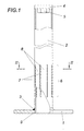
- the illustrated stop device for fall protection has an anchor plate 1 with a support tube 2, which with the anchor plate 1 via a Weld 3 is connected. At the end of the support tube 2 facing away from the anchor plate 1, an end cap 4 is welded with a threaded nut 5, into which, for example, an attachment point for receiving a personal protective equipment or a holder for a guide is screwed, along which a movable attachment point can be moved.
- the support tube 2 in a subsequent to the weld 3 between the support tube 2 and the anchor plate 1 axial portion 6 around the circumference evenly distributed axial slots 7, which have an approximately twice the outer diameter of the support tube 2 corresponding length , Because of these axial slots 7, the support tube 2 is weakened in the axial portion 6 with the effect that the flexural rigidity of this section 6 from a predetermined torque load of the support tube 2 by transverse forces, as they occur in a fall, exceeded and the support tube 2 is bent.
- axial slots 7 Because of these axial slots 7, the support tube 2 is weakened in the axial portion 6 with the effect that the flexural rigidity of this section 6 from a predetermined torque load of the support tube 2 by transverse forces, as they occur in a fall, exceeded and the support tube 2 is bent.
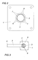
- the bent support tube 2 is shown in a plan view, it can be seen that in this bending process, the claimed webs 8 bend between the axial slots 7 essentially only about a transverse axis, while the located in the pressure zones webs 8 additionally buckle.
- the associated deformation work consumes a portion of the kinetic energy of the fall and thus helps to catch the falling gently.
- the risk of cracking in the region of the weld 3 is eliminated by tensile forces, which are transmitted via the support tube 2 to the weld 3, because the support tube 2 is bent before the occurrence of cracks.
- the support tube 2 is not stumped placed on the anchor plate 1, but engages positively in a passage opening 9 of the anchor plate 1 a. This means that acting on the support tube 2 transverse forces can be transmitted in part via the engaging into the passage opening 9 edge region of the support tube 2 directly to the anchor plate 1, which brings an additional relief of the weld 3 with it.
Abstract
Description
Die Erfindung bezieht sich auf eine Anschlagvorrichtung für eine Absturzsicherung mit einer Ankerplatte und mit einem auf der Ankerplatte durch eine Schweißnaht befestigten Stützrohr zur Aufnahme eines Anschlagpunktes oder einer Führung für einen beweglichen Anschlagpunkt.The invention relates to a stop device for a fall protection with an anchor plate and with a mounted on the anchor plate by a weld support tube for receiving a stop point or a guide for a movable attachment point.
Zum Anschlagen persönlicher Schutzausrüstungen auf der Dachfläche eines Gebäudes sind Anschlagvorrichtungen bekannt, die aus einer Ankerplatte und einem auf der Ankerplatte angeschweißten Stützrohr bestehen, das an seinem freien Ende einen Anschlagpunkt oder eine Führung für einen beweglichen Anschlagpunkt zum Befestigen der persönlichen Schutzausrüstung trägt. In beiden Fällen müssen die auftretenden Belastungen vom Stützrohr über die Schweißnaht auf die Ankerplatte und über die Ankerplatte auf das Bauwerk abgetragen werden, wobei statische und dynamische Belastungen zu berücksichtigen sind. Diese Belastungen, die über den Anschlagpunkt bzw. die Führung für einen solchen Anschlagpunkt als Querkräfte am Stützrohr angreifen, bedingen einerseits eine Biegebeanspruchung des Stützrohres und anderseits ein Drehmoment, das eine Zugbelastung der Schweißverbindung zwischen dem Stützrohr und der Ankerplatte mit sich bringt. Die geforderte statische Belastbarkeit erzwingt ausreichend große Durchmesser für das Stützrohr, um die Rissgefahr im Bereich der Schweißnaht zufolge der zu erwartenden Zugbelastungen vermeiden zu können. Mit der Vergrößerung des Durchmessers des Stützrohres vergrößert sich aber dessen Widerstandsmoment gegenüber einer plastische Biegeverformung, was sich bei einem Sturz und der damit verbundenen dynamischen Belastung nachteilig auswirkt, und zwar nicht nur hinsichtlich der Belastung der aufzufangenden Person, sondern auch bezüglich der Befestigung der Ankerplatte am Bauwerk. Dies bedeutet, dass die Ankerplatte ausreichend groß zu wählen ist, um die Ausziehkräfte auf die eingesetzten Befestigungsmittel in zulässigen Grenzen halten zu können. Um sowohl den statischen als auch den dynamischen Belastungsanforderungen vorteilhaft entsprechen zu können, ist es bereits bekannt (
Der Erfindung liegt somit die Aufgabe zugrunde, eine Anschlagvorrichtung für eine Absturzsicherung der eingangs geschilderten Art so auszugestalten, dass eine einfache Bauweise sichergestellt werden kann, ohne auf eine vorteilhafte Abtragung sowohl der statischen als auch der dynamischen Belastungsanforderungen verzichten zu müssen.The invention is therefore based on the object, a stop device for a fall protection of the type described in such a way that a simple construction can be ensured without sacrificing an advantageous removal of both the static and the dynamic load requirements.
Die Erfindung löst die gestellte Aufgabe dadurch, dass das Stützrohr in einem an die Schweißnaht anschließenden axialen Abschnitt über seinen Umfang verteilte Axialschlitze aufweist.The invention achieves the stated object in that the support tube has axial slots distributed over its circumference in an axial section adjoining the weld seam.
Aufgrund dieser Axialschlitze im Stützrohr werden die zufolge von Querkräften auf die Schweißnaht zwischen dem Stützrohr und der Ankerplatte einwirkenden Zugkräfte beschränkt, weil das mit diesen Querkräften verbundene Drehmoment beim Überschreiten einer vorgegebenen Größe eine Überlastung des Stützrohres im Bereich des durch die Axialschlitze geschwächten Abschnittes mit sich bringt, sodass sich das Stützrohr im Bereich dieses geschwächten Abschnittes plastisch verformt. Die damit verbundene Formänderungsarbeit verbraucht einen Teil der kinetischen Energie beim Auffangen eines Stürzenden, der somit einer geringeren Stoßbelastung unterworfen wird, zumal sich ein zusätzlicher Auffangweg durch die Verlagerung des Anschlagpunktes beim Umbiegen des Stützrohres ergibt.Due to these axial slots in the support tube, the tensile forces acting on the weld seam between the support tube and the anchor plate are limited due to the fact that the torque associated with these transverse forces when exceeding a predetermined size causes overloading of the support tube in the weakened by the axial slots section so that the support tube plastically deforms in the region of this weakened section. The associated deformation work consumes a portion of the kinetic energy in catching a falling end, which is thus subjected to a lower impact load, especially since an additional Falling path results from the displacement of the attachment point when bending the support tube.
Wird das Stützrohr in eine Durchtrittsöffnung der Ankerplatte formschlüssig eingesetzt und dann mit der Ankerplatte verschweißt, so kann eine zusätzliche Entlastung der Schweißnaht zwischen der Ankerplatte und dem Stützrohr erreicht werden, weil über den in die Durchtrittsöffnung der Ankerplatte eingreifenden Randabschnitt des Stützrohres ein Teil der auf das Stützrohr wirksamen Querkräfte unmittelbar auf die Ankerplatte übertragen werden kann, was mit einer Entlastung der Schweißnaht verbunden ist.If the support tube is inserted positively into a passage opening of the anchor plate and then welded to the anchor plate, an additional relief of the weld between the anchor plate and the support tube can be achieved, because on the engaging in the passage opening of the anchor plate edge portion of the support tube, a part of the Supporting tube effective lateral forces can be transmitted directly to the anchor plate, which is associated with a relief of the weld.
Die Schwächung des Stützrohres durch die Axialschlitze kann durch eine geeignete Wahl der Schlitzlänge an die jeweiligen Verhältnisse angepasst werden, wobei sich im Allgemeinen Schlitzlängen ergeben, die dem einfachen bis dreifachen Außendurchmesser, vorzugsweise etwa dem doppelten Außendurchmesser, des Stützrohres entsprechen. Die Schlitzanzahl stellt eine andere Einflussgröße auf das Biegeverhalten des Stützrohres im Bereich der Axialschlitze dar, wobei darauf zu achten ist, dass von der Angriffsrichtung der Querkräfte weitgehend unabhängige Biegeeigenschaften sichergestellt werden. Aus diesem Grund sollen zumindest vier, vorzugsweise zumindest sechs, Axialschlitze über den Umfang des Stützrohres gleichmäßig verteilt angeordnet werden.The weakening of the support tube through the axial slots can be adapted by a suitable choice of the slot length to the respective conditions, resulting in general slot lengths corresponding to the simple to triple outer diameter, preferably about twice the outer diameter of the support tube. The number of slots represents another factor influencing the bending behavior of the support tube in the region of the axial slots, it being important to ensure that largely independent bending properties are ensured by the direction of attack of the transverse forces. For this reason, at least four, preferably at least six, axial slots should be arranged uniformly distributed over the circumference of the support tube.
In der Zeichnung ist der Erfindungsgegenstand in einem Ausführungsbeispiel dargestellt. Es zeigen
- Fig. 1
- eine erfindungsgemäße Anschlagvorrichtung für eine Absturzsicherung in einer zum Teil aufgerissenen Seitenansicht,
- Fig. 2
- diese Anschlagvorrichtung in einem Schnitt nach der Linie II-II der
Fig. 1 und - Fig. 3
- eine Draufsicht auf die Anschlagvorrichtung mit umgebogenem Stützrohr in einem kleineren Maßstab.
- Fig. 1
- a stop device according to the invention for a fall protection in a partially torn side view,
- Fig. 2
- this stop device in a section along the line II-II of
Fig. 1 and - Fig. 3
- a plan view of the stop device with bent support tube on a smaller scale.
Die dargestellte Anschlagvorrichtung für eine Absturzsicherung weist eine Ankerplatte 1 mit einem Stützrohr 2 auf, das mit der Ankerplatte 1 über eine Schweißnaht 3 verbunden ist. An dem der Ankerplatte 1 abgekehrten Ende des Stützrohres 2 ist eine Endkappe 4 mit einer Gewindemutter 5 aufgeschweißt, in die beispielsweise ein Anschlagpunkt zur Aufnahme einer persönlichen Schutzausrüstung oder eine Halterung für eine Führung eingeschraubt wird, entlang der ein beweglicher Anschlagpunkt verlagert werden kann.The illustrated stop device for fall protection has an
Zum Unterschied von herkömmlichen Anschlagvorrichtungen dieser Art weist das Stützrohr 2 in einem an die Schweißnaht 3 zwischen dem Stützrohr 2 und der Ankerplatte 1 anschließenden axialen Abschnitt 6 um den Umfang gleichmäßig verteilte Axialschlitze 7 auf, die eine etwa dem doppelten Außendurchmesser des Stützrohres 2 entsprechende Länge besitzen. Aufgrund dieser Axialschlitze 7 wird das Stützrohr 2 im Bereich des axialen Abschnittes 6 mit der Wirkung geschwächt, dass die Biegesteifigkeit dieses Abschnittes 6 ab einer vorgegebenen Drehmomentbelastung des Stützrohres 2 durch Querkräfte, wie sie bei einem Sturz auftreten, überschritten und das Stützrohr 2 umgebogen wird. In der
Wie sich aus der
Claims (4)
Applications Claiming Priority (1)
| Application Number | Priority Date | Filing Date | Title |
|---|---|---|---|
| AT0027208A AT506224B1 (en) | 2008-02-20 | 2008-02-20 | STOPPING DEVICE FOR FALLING SAFETY |
Publications (2)
| Publication Number | Publication Date |
|---|---|
| EP2093350A1 true EP2093350A1 (en) | 2009-08-26 |
| EP2093350B1 EP2093350B1 (en) | 2011-01-19 |
Family
ID=40671067
Family Applications (1)
| Application Number | Title | Priority Date | Filing Date |
|---|---|---|---|
| EP09450012A Not-in-force EP2093350B1 (en) | 2008-02-20 | 2009-01-23 | Impact device for crash guard |
Country Status (4)
| Country | Link |
|---|---|
| EP (1) | EP2093350B1 (en) |
| AT (2) | AT506224B1 (en) |
| DE (1) | DE502009000292D1 (en) |
| ES (1) | ES2358970T3 (en) |
Cited By (1)
| Publication number | Priority date | Publication date | Assignee | Title |
|---|---|---|---|---|
| FR2966181A1 (en) * | 2010-10-19 | 2012-04-20 | Frenehard & Michaux Sa | Rail anchor for safety system that is arranged on roof of building, has drawing element that is allowed to bend with tubular body relative to prop on base plate in position parallel with base plate when traction force is applied |
Families Citing this family (4)
| Publication number | Priority date | Publication date | Assignee | Title |
|---|---|---|---|---|
| NL2007622C2 (en) * | 2011-10-19 | 2013-04-22 | Waijers Anthony | DYNAMIC ANCHOR POINT AND FALL PROTECTION DEVICE. |
| FR2987638B1 (en) * | 2012-03-02 | 2014-12-26 | Acrotir Travaux Acrobatiques De L Est Acrotir T A E | FALL BRAKE DEVICE |
| ITBZ20120034A1 (en) * | 2012-10-12 | 2014-04-13 | Hb Security Srl | DEFORMABLE POLE FOR SUPPORT FOR FLEXIBLE PROTECTION LINES |
| ITMI20131618A1 (en) * | 2013-10-01 | 2015-04-02 | Si Al S R L | ANCHORAGE DEVICE FOR LIFE LINE |
Citations (5)
| Publication number | Priority date | Publication date | Assignee | Title |
|---|---|---|---|---|
| DE10318322B3 (en) * | 2003-04-19 | 2004-11-04 | Steinmetz, Jürgen | Stopping point for a cable protection for a roof comprises a tubular sleeve surrounding a holding rod tensioned between a base plate connected to a roof and a hanging eyelet |
| DE10333113B3 (en) * | 2003-07-21 | 2004-11-18 | Optigrün international AG | Fall prevention device for protection of worker on flat roof has bearing plate with projecting post provided with fastening element for safety line at its top end |
| DE202005006654U1 (en) * | 2004-04-29 | 2005-09-08 | Reiter, Gerald | Stop for anti-derail device has pipe section welded to anchor plate that engages in end of supporting tube facing anchor plate, preferably without play |
| EP1693533A1 (en) * | 2005-02-18 | 2006-08-23 | Jörg Häring | Fall restraint with fall dampener |
| DE202006018193U1 (en) * | 2006-11-29 | 2007-04-05 | Dl Fischer Gmbh | Fall prevention device has vertical, horizontal or sloped surfaces of construction wherein several holes are present in base plate and by which base plate is fixed or attached to construction |
Family Cites Families (1)
| Publication number | Priority date | Publication date | Assignee | Title |
|---|---|---|---|---|
| DE102006029739B4 (en) * | 2006-06-28 | 2008-07-03 | St Quadrat S.A. | Attachment point for a rope protection |
-
2008
- 2008-02-20 AT AT0027208A patent/AT506224B1/en not_active IP Right Cessation
-
2009
- 2009-01-23 ES ES09450012T patent/ES2358970T3/en active Active
- 2009-01-23 AT AT09450012T patent/ATE496184T1/en active
- 2009-01-23 DE DE502009000292T patent/DE502009000292D1/en active Active
- 2009-01-23 EP EP09450012A patent/EP2093350B1/en not_active Not-in-force
Patent Citations (6)
| Publication number | Priority date | Publication date | Assignee | Title |
|---|---|---|---|---|
| DE10318322B3 (en) * | 2003-04-19 | 2004-11-04 | Steinmetz, Jürgen | Stopping point for a cable protection for a roof comprises a tubular sleeve surrounding a holding rod tensioned between a base plate connected to a roof and a hanging eyelet |
| DE10333113B3 (en) * | 2003-07-21 | 2004-11-18 | Optigrün international AG | Fall prevention device for protection of worker on flat roof has bearing plate with projecting post provided with fastening element for safety line at its top end |
| DE202005006654U1 (en) * | 2004-04-29 | 2005-09-08 | Reiter, Gerald | Stop for anti-derail device has pipe section welded to anchor plate that engages in end of supporting tube facing anchor plate, preferably without play |
| AT8353U1 (en) | 2004-04-29 | 2006-06-15 | Reiter Gerald | STOPPING DEVICE FOR FALLING SAFETY |
| EP1693533A1 (en) * | 2005-02-18 | 2006-08-23 | Jörg Häring | Fall restraint with fall dampener |
| DE202006018193U1 (en) * | 2006-11-29 | 2007-04-05 | Dl Fischer Gmbh | Fall prevention device has vertical, horizontal or sloped surfaces of construction wherein several holes are present in base plate and by which base plate is fixed or attached to construction |
Cited By (1)
| Publication number | Priority date | Publication date | Assignee | Title |
|---|---|---|---|---|
| FR2966181A1 (en) * | 2010-10-19 | 2012-04-20 | Frenehard & Michaux Sa | Rail anchor for safety system that is arranged on roof of building, has drawing element that is allowed to bend with tubular body relative to prop on base plate in position parallel with base plate when traction force is applied |
Also Published As
| Publication number | Publication date |
|---|---|
| ATE496184T1 (en) | 2011-02-15 |
| AT506224A4 (en) | 2009-07-15 |
| ES2358970T3 (en) | 2011-05-17 |
| DE502009000292D1 (en) | 2011-03-03 |
| AT506224B1 (en) | 2009-07-15 |
| EP2093350B1 (en) | 2011-01-19 |
Similar Documents
| Publication | Publication Date | Title |
|---|---|---|
| EP2093350B1 (en) | Impact device for crash guard | |
| DE3112640C2 (en) | Cable gland | |
| EP2274535A1 (en) | Device for the impact damping of cable constructions, in particular for barrier structures for falling rock, mud flows and snow | |
| AT11927U1 (en) | FALL PROTECTION | |
| DE102010021429A1 (en) | Fastening device, in particular for wall-hung sanitary objects | |
| WO2000055869A1 (en) | Surge voltage protector with at least one tension element | |
| EP3507432B1 (en) | Device for preventing persons from falling | |
| DE102007041184B4 (en) | thrust washer | |
| DE102008008577A1 (en) | fall Protection | |
| DE202005006654U1 (en) | Stop for anti-derail device has pipe section welded to anchor plate that engages in end of supporting tube facing anchor plate, preferably without play | |
| DE1101328B (en) | Overload protection with an exchangeable breaker link between machine parts subjected to pressure | |
| DE10320100B4 (en) | Technical installation with a number of system components each supported by a number of carriers and with a number of pressure-carrying lines, in particular for use in a nuclear power plant | |
| DE2524625A1 (en) | DEVICE FOR CONNECTING TWO BODIES | |
| DE2337801B2 (en) | DEVICE FOR CONNECTING TWO FIBER-REINFORCED PLASTIC PIPES BY SCREWING TOGETHER | |
| DE202013100837U1 (en) | Energy-absorbing terminal of a protective device located to the side of a roadway | |
| AT500522B1 (en) | STOPPING DEVICE FOR FALLING SAFETY | |
| EP3975358A1 (en) | Bracket for holding cables, preferably highvoltage cables | |
| DE102019219440B3 (en) | Tensioner drive for a belt retractor | |
| DE2658360A1 (en) | Captive bolt securing device - has spring bearing against bolt head and secured at point above it | |
| DE2103696C3 (en) | Rod-shaped striking tool | |
| EP1683931A2 (en) | Fastening device for a fall protection device | |
| EP2874871B1 (en) | Device for mounting a marine engine on an engine pedestal | |
| DE202016009060U1 (en) | Shear cylinder with grooves | |
| DE805216C (en) | Tool for removing broken taps | |
| DE202010014242U1 (en) | centering |
Legal Events
| Date | Code | Title | Description |
|---|---|---|---|
| PUAI | Public reference made under article 153(3) epc to a published international application that has entered the european phase |
Free format text: ORIGINAL CODE: 0009012 |
|
| AK | Designated contracting states |
Kind code of ref document: A1 Designated state(s): AT BE BG CH CY CZ DE DK EE ES FI FR GB GR HR HU IE IS IT LI LT LU LV MC MK MT NL NO PL PT RO SE SI SK TR |
|
| AX | Request for extension of the european patent |
Extension state: AL BA RS |
|
| 17P | Request for examination filed |
Effective date: 20090929 |
|
| AKX | Designation fees paid |
Designated state(s): AT BE BG CH CY CZ DE DK EE ES FI FR GB GR HR HU IE IS IT LI LT LU LV MC MK MT NL NO PL PT RO SE SI SK TR |
|
| GRAP | Despatch of communication of intention to grant a patent |
Free format text: ORIGINAL CODE: EPIDOSNIGR1 |
|
| GRAS | Grant fee paid |
Free format text: ORIGINAL CODE: EPIDOSNIGR3 |
|
| GRAA | (expected) grant |
Free format text: ORIGINAL CODE: 0009210 |
|
| AK | Designated contracting states |
Kind code of ref document: B1 Designated state(s): AT BE BG CH CY CZ DE DK EE ES FI FR GB GR HR HU IE IS IT LI LT LU LV MC MK MT NL NO PL PT RO SE SI SK TR |
|
| REG | Reference to a national code |
Ref country code: GB Ref legal event code: FG4D Free format text: NOT ENGLISH |
|
| REG | Reference to a national code |
Ref country code: CH Ref legal event code: EP |
|
| REG | Reference to a national code |
Ref country code: CH Ref legal event code: NV Representative=s name: E. BLUM & CO. AG PATENT- UND MARKENANWAELTE VSP |
|
| REG | Reference to a national code |
Ref country code: IE Ref legal event code: FG4D Free format text: LANGUAGE OF EP DOCUMENT: GERMAN |
|
| REF | Corresponds to: |
Ref document number: 502009000292 Country of ref document: DE Date of ref document: 20110303 Kind code of ref document: P |
|
| REG | Reference to a national code |
Ref country code: DE Ref legal event code: R096 Ref document number: 502009000292 Country of ref document: DE Effective date: 20110303 |
|
| REG | Reference to a national code |
Ref country code: ES Ref legal event code: FG2A Ref document number: 2358970 Country of ref document: ES Kind code of ref document: T3 Effective date: 20110517 |
|
| REG | Reference to a national code |
Ref country code: NL Ref legal event code: VDEP Effective date: 20110119 |
|
| LTIE | Lt: invalidation of european patent or patent extension |
Effective date: 20110119 |
|
| PG25 | Lapsed in a contracting state [announced via postgrant information from national office to epo] |
Ref country code: GR Free format text: LAPSE BECAUSE OF FAILURE TO SUBMIT A TRANSLATION OF THE DESCRIPTION OR TO PAY THE FEE WITHIN THE PRESCRIBED TIME-LIMIT Effective date: 20110420 Ref country code: NO Free format text: LAPSE BECAUSE OF FAILURE TO SUBMIT A TRANSLATION OF THE DESCRIPTION OR TO PAY THE FEE WITHIN THE PRESCRIBED TIME-LIMIT Effective date: 20110419 Ref country code: SE Free format text: LAPSE BECAUSE OF FAILURE TO SUBMIT A TRANSLATION OF THE DESCRIPTION OR TO PAY THE FEE WITHIN THE PRESCRIBED TIME-LIMIT Effective date: 20110119 Ref country code: PT Free format text: LAPSE BECAUSE OF FAILURE TO SUBMIT A TRANSLATION OF THE DESCRIPTION OR TO PAY THE FEE WITHIN THE PRESCRIBED TIME-LIMIT Effective date: 20110519 Ref country code: LV Free format text: LAPSE BECAUSE OF FAILURE TO SUBMIT A TRANSLATION OF THE DESCRIPTION OR TO PAY THE FEE WITHIN THE PRESCRIBED TIME-LIMIT Effective date: 20110119 Ref country code: IS Free format text: LAPSE BECAUSE OF FAILURE TO SUBMIT A TRANSLATION OF THE DESCRIPTION OR TO PAY THE FEE WITHIN THE PRESCRIBED TIME-LIMIT Effective date: 20110519 Ref country code: HR Free format text: LAPSE BECAUSE OF FAILURE TO SUBMIT A TRANSLATION OF THE DESCRIPTION OR TO PAY THE FEE WITHIN THE PRESCRIBED TIME-LIMIT Effective date: 20110119 Ref country code: LT Free format text: LAPSE BECAUSE OF FAILURE TO SUBMIT A TRANSLATION OF THE DESCRIPTION OR TO PAY THE FEE WITHIN THE PRESCRIBED TIME-LIMIT Effective date: 20110119 |
|
| REG | Reference to a national code |
Ref country code: IE Ref legal event code: FD4D |
|
| PG25 | Lapsed in a contracting state [announced via postgrant information from national office to epo] |
Ref country code: SI Free format text: LAPSE BECAUSE OF FAILURE TO SUBMIT A TRANSLATION OF THE DESCRIPTION OR TO PAY THE FEE WITHIN THE PRESCRIBED TIME-LIMIT Effective date: 20110119 Ref country code: NL Free format text: LAPSE BECAUSE OF FAILURE TO SUBMIT A TRANSLATION OF THE DESCRIPTION OR TO PAY THE FEE WITHIN THE PRESCRIBED TIME-LIMIT Effective date: 20110119 Ref country code: FI Free format text: LAPSE BECAUSE OF FAILURE TO SUBMIT A TRANSLATION OF THE DESCRIPTION OR TO PAY THE FEE WITHIN THE PRESCRIBED TIME-LIMIT Effective date: 20110119 Ref country code: MC Free format text: LAPSE BECAUSE OF NON-PAYMENT OF DUE FEES Effective date: 20110131 Ref country code: PL Free format text: LAPSE BECAUSE OF FAILURE TO SUBMIT A TRANSLATION OF THE DESCRIPTION OR TO PAY THE FEE WITHIN THE PRESCRIBED TIME-LIMIT Effective date: 20110119 Ref country code: CY Free format text: LAPSE BECAUSE OF FAILURE TO SUBMIT A TRANSLATION OF THE DESCRIPTION OR TO PAY THE FEE WITHIN THE PRESCRIBED TIME-LIMIT Effective date: 20110119 Ref country code: BG Free format text: LAPSE BECAUSE OF FAILURE TO SUBMIT A TRANSLATION OF THE DESCRIPTION OR TO PAY THE FEE WITHIN THE PRESCRIBED TIME-LIMIT Effective date: 20110419 |
|
| PG25 | Lapsed in a contracting state [announced via postgrant information from national office to epo] |
Ref country code: EE Free format text: LAPSE BECAUSE OF FAILURE TO SUBMIT A TRANSLATION OF THE DESCRIPTION OR TO PAY THE FEE WITHIN THE PRESCRIBED TIME-LIMIT Effective date: 20110119 Ref country code: DK Free format text: LAPSE BECAUSE OF FAILURE TO SUBMIT A TRANSLATION OF THE DESCRIPTION OR TO PAY THE FEE WITHIN THE PRESCRIBED TIME-LIMIT Effective date: 20110119 Ref country code: IE Free format text: LAPSE BECAUSE OF FAILURE TO SUBMIT A TRANSLATION OF THE DESCRIPTION OR TO PAY THE FEE WITHIN THE PRESCRIBED TIME-LIMIT Effective date: 20110119 |
|
| PLBE | No opposition filed within time limit |
Free format text: ORIGINAL CODE: 0009261 |
|
| STAA | Information on the status of an ep patent application or granted ep patent |
Free format text: STATUS: NO OPPOSITION FILED WITHIN TIME LIMIT |
|
| PG25 | Lapsed in a contracting state [announced via postgrant information from national office to epo] |
Ref country code: CZ Free format text: LAPSE BECAUSE OF FAILURE TO SUBMIT A TRANSLATION OF THE DESCRIPTION OR TO PAY THE FEE WITHIN THE PRESCRIBED TIME-LIMIT Effective date: 20110119 Ref country code: SK Free format text: LAPSE BECAUSE OF FAILURE TO SUBMIT A TRANSLATION OF THE DESCRIPTION OR TO PAY THE FEE WITHIN THE PRESCRIBED TIME-LIMIT Effective date: 20110119 Ref country code: RO Free format text: LAPSE BECAUSE OF FAILURE TO SUBMIT A TRANSLATION OF THE DESCRIPTION OR TO PAY THE FEE WITHIN THE PRESCRIBED TIME-LIMIT Effective date: 20110119 |
|
| 26N | No opposition filed |
Effective date: 20111020 |
|
| PG25 | Lapsed in a contracting state [announced via postgrant information from national office to epo] |
Ref country code: MT Free format text: LAPSE BECAUSE OF FAILURE TO SUBMIT A TRANSLATION OF THE DESCRIPTION OR TO PAY THE FEE WITHIN THE PRESCRIBED TIME-LIMIT Effective date: 20110119 |
|
| REG | Reference to a national code |
Ref country code: DE Ref legal event code: R097 Ref document number: 502009000292 Country of ref document: DE Effective date: 20111020 |
|
| PG25 | Lapsed in a contracting state [announced via postgrant information from national office to epo] |
Ref country code: MK Free format text: LAPSE BECAUSE OF FAILURE TO SUBMIT A TRANSLATION OF THE DESCRIPTION OR TO PAY THE FEE WITHIN THE PRESCRIBED TIME-LIMIT Effective date: 20110119 |
|
| PG25 | Lapsed in a contracting state [announced via postgrant information from national office to epo] |
Ref country code: LU Free format text: LAPSE BECAUSE OF NON-PAYMENT OF DUE FEES Effective date: 20110123 |
|
| PG25 | Lapsed in a contracting state [announced via postgrant information from national office to epo] |
Ref country code: TR Free format text: LAPSE BECAUSE OF FAILURE TO SUBMIT A TRANSLATION OF THE DESCRIPTION OR TO PAY THE FEE WITHIN THE PRESCRIBED TIME-LIMIT Effective date: 20110119 |
|
| PG25 | Lapsed in a contracting state [announced via postgrant information from national office to epo] |
Ref country code: HU Free format text: LAPSE BECAUSE OF FAILURE TO SUBMIT A TRANSLATION OF THE DESCRIPTION OR TO PAY THE FEE WITHIN THE PRESCRIBED TIME-LIMIT Effective date: 20110119 |
|
| REG | Reference to a national code |
Ref country code: FR Ref legal event code: PLFP Year of fee payment: 7 |
|
| PGFP | Annual fee paid to national office [announced via postgrant information from national office to epo] |
Ref country code: ES Payment date: 20141222 Year of fee payment: 7 |
|
| REG | Reference to a national code |
Ref country code: AT Ref legal event code: MM01 Ref document number: 496184 Country of ref document: AT Kind code of ref document: T Effective date: 20140123 |
|
| PGFP | Annual fee paid to national office [announced via postgrant information from national office to epo] |
Ref country code: DE Payment date: 20150131 Year of fee payment: 7 Ref country code: CH Payment date: 20141230 Year of fee payment: 7 Ref country code: IT Payment date: 20150124 Year of fee payment: 7 |
|
| PG25 | Lapsed in a contracting state [announced via postgrant information from national office to epo] |
Ref country code: AT Free format text: LAPSE BECAUSE OF NON-PAYMENT OF DUE FEES Effective date: 20140123 |
|
| PGFP | Annual fee paid to national office [announced via postgrant information from national office to epo] |
Ref country code: FR Payment date: 20150129 Year of fee payment: 7 Ref country code: GB Payment date: 20150129 Year of fee payment: 7 |
|
| PGFP | Annual fee paid to national office [announced via postgrant information from national office to epo] |
Ref country code: BE Payment date: 20141224 Year of fee payment: 7 |
|
| PG25 | Lapsed in a contracting state [announced via postgrant information from national office to epo] |
Ref country code: BE Free format text: LAPSE BECAUSE OF NON-PAYMENT OF DUE FEES Effective date: 20160131 |
|
| REG | Reference to a national code |
Ref country code: DE Ref legal event code: R119 Ref document number: 502009000292 Country of ref document: DE |
|
| REG | Reference to a national code |
Ref country code: CH Ref legal event code: PL |
|
| GBPC | Gb: european patent ceased through non-payment of renewal fee |
Effective date: 20160123 |
|
| REG | Reference to a national code |
Ref country code: FR Ref legal event code: ST Effective date: 20160930 |
|
| PG25 | Lapsed in a contracting state [announced via postgrant information from national office to epo] |
Ref country code: CH Free format text: LAPSE BECAUSE OF NON-PAYMENT OF DUE FEES Effective date: 20160131 Ref country code: LI Free format text: LAPSE BECAUSE OF NON-PAYMENT OF DUE FEES Effective date: 20160131 Ref country code: GB Free format text: LAPSE BECAUSE OF NON-PAYMENT OF DUE FEES Effective date: 20160123 Ref country code: DE Free format text: LAPSE BECAUSE OF NON-PAYMENT OF DUE FEES Effective date: 20160802 |
|
| PG25 | Lapsed in a contracting state [announced via postgrant information from national office to epo] |
Ref country code: FR Free format text: LAPSE BECAUSE OF NON-PAYMENT OF DUE FEES Effective date: 20160201 |
|
| PG25 | Lapsed in a contracting state [announced via postgrant information from national office to epo] |
Ref country code: IT Free format text: LAPSE BECAUSE OF NON-PAYMENT OF DUE FEES Effective date: 20160123 |
|
| PG25 | Lapsed in a contracting state [announced via postgrant information from national office to epo] |
Ref country code: ES Free format text: LAPSE BECAUSE OF NON-PAYMENT OF DUE FEES Effective date: 20160124 |