EP2093083A2 - Klimaanlage - Google Patents
Klimaanlage Download PDFInfo
- Publication number
- EP2093083A2 EP2093083A2 EP09162867A EP09162867A EP2093083A2 EP 2093083 A2 EP2093083 A2 EP 2093083A2 EP 09162867 A EP09162867 A EP 09162867A EP 09162867 A EP09162867 A EP 09162867A EP 2093083 A2 EP2093083 A2 EP 2093083A2
- Authority
- EP
- European Patent Office
- Prior art keywords
- heat exchanger
- valve
- compressor
- strand
- air conditioning
- Prior art date
- Legal status (The legal status is an assumption and is not a legal conclusion. Google has not performed a legal analysis and makes no representation as to the accuracy of the status listed.)
- Granted
Links
Images




Classifications
-
- B—PERFORMING OPERATIONS; TRANSPORTING
- B60—VEHICLES IN GENERAL
- B60H—ARRANGEMENTS OF HEATING, COOLING, VENTILATING OR OTHER AIR-TREATING DEVICES SPECIALLY ADAPTED FOR PASSENGER OR GOODS SPACES OF VEHICLES
- B60H1/00—Heating, cooling or ventilating devices
- B60H1/00642—Control systems or circuits; Control members or indication devices for heating, cooling or ventilating devices
- B60H1/00814—Control systems or circuits characterised by their output, for controlling particular components of the heating, cooling or ventilating installation
- B60H1/00878—Control systems or circuits characterised by their output, for controlling particular components of the heating, cooling or ventilating installation the components being temperature regulating devices
- B60H1/00899—Controlling the flow of liquid in a heat pump system
- B60H1/00907—Controlling the flow of liquid in a heat pump system where the flow direction of the refrigerant changes and an evaporator becomes condenser
-
- F—MECHANICAL ENGINEERING; LIGHTING; HEATING; WEAPONS; BLASTING
- F24—HEATING; RANGES; VENTILATING
- F24F—AIR-CONDITIONING; AIR-HUMIDIFICATION; VENTILATION; USE OF AIR CURRENTS FOR SCREENING
- F24F3/00—Air-conditioning systems in which conditioned primary air is supplied from one or more central stations to distributing units in the rooms or spaces where it may receive secondary treatment; Apparatus specially designed for such systems
- F24F3/12—Air-conditioning systems in which conditioned primary air is supplied from one or more central stations to distributing units in the rooms or spaces where it may receive secondary treatment; Apparatus specially designed for such systems characterised by the treatment of the air otherwise than by heating and cooling
- F24F3/14—Air-conditioning systems in which conditioned primary air is supplied from one or more central stations to distributing units in the rooms or spaces where it may receive secondary treatment; Apparatus specially designed for such systems characterised by the treatment of the air otherwise than by heating and cooling by humidification; by dehumidification
- F24F3/153—Air-conditioning systems in which conditioned primary air is supplied from one or more central stations to distributing units in the rooms or spaces where it may receive secondary treatment; Apparatus specially designed for such systems characterised by the treatment of the air otherwise than by heating and cooling by humidification; by dehumidification with subsequent heating, i.e. with the air, given the required humidity in the central station, passing a heating element to achieve the required temperature
-
- F—MECHANICAL ENGINEERING; LIGHTING; HEATING; WEAPONS; BLASTING
- F25—REFRIGERATION OR COOLING; COMBINED HEATING AND REFRIGERATION SYSTEMS; HEAT PUMP SYSTEMS; MANUFACTURE OR STORAGE OF ICE; LIQUEFACTION SOLIDIFICATION OF GASES
- F25B—REFRIGERATION MACHINES, PLANTS OR SYSTEMS; COMBINED HEATING AND REFRIGERATION SYSTEMS; HEAT PUMP SYSTEMS
- F25B41/00—Fluid-circulation arrangements
- F25B41/20—Disposition of valves, e.g. of on-off valves or flow control valves
-
- F—MECHANICAL ENGINEERING; LIGHTING; HEATING; WEAPONS; BLASTING
- F25—REFRIGERATION OR COOLING; COMBINED HEATING AND REFRIGERATION SYSTEMS; HEAT PUMP SYSTEMS; MANUFACTURE OR STORAGE OF ICE; LIQUEFACTION SOLIDIFICATION OF GASES
- F25B—REFRIGERATION MACHINES, PLANTS OR SYSTEMS; COMBINED HEATING AND REFRIGERATION SYSTEMS; HEAT PUMP SYSTEMS
- F25B41/00—Fluid-circulation arrangements
- F25B41/20—Disposition of valves, e.g. of on-off valves or flow control valves
- F25B41/24—Arrangement of shut-off valves for disconnecting a part of the refrigerant cycle, e.g. an outdoor part
-
- B—PERFORMING OPERATIONS; TRANSPORTING
- B60—VEHICLES IN GENERAL
- B60H—ARRANGEMENTS OF HEATING, COOLING, VENTILATING OR OTHER AIR-TREATING DEVICES SPECIALLY ADAPTED FOR PASSENGER OR GOODS SPACES OF VEHICLES
- B60H1/00—Heating, cooling or ventilating devices
- B60H1/00642—Control systems or circuits; Control members or indication devices for heating, cooling or ventilating devices
- B60H1/00814—Control systems or circuits characterised by their output, for controlling particular components of the heating, cooling or ventilating installation
- B60H1/00878—Control systems or circuits characterised by their output, for controlling particular components of the heating, cooling or ventilating installation the components being temperature regulating devices
- B60H2001/00957—Control systems or circuits characterised by their output, for controlling particular components of the heating, cooling or ventilating installation the components being temperature regulating devices comprising locations with heat exchange within the refrigerant circuit itself, e.g. cross-, counter-, or parallel heat exchange
-
- F—MECHANICAL ENGINEERING; LIGHTING; HEATING; WEAPONS; BLASTING
- F25—REFRIGERATION OR COOLING; COMBINED HEATING AND REFRIGERATION SYSTEMS; HEAT PUMP SYSTEMS; MANUFACTURE OR STORAGE OF ICE; LIQUEFACTION SOLIDIFICATION OF GASES
- F25B—REFRIGERATION MACHINES, PLANTS OR SYSTEMS; COMBINED HEATING AND REFRIGERATION SYSTEMS; HEAT PUMP SYSTEMS
- F25B2309/00—Gas cycle refrigeration machines
- F25B2309/06—Compression machines, plants or systems characterised by the refrigerant being carbon dioxide
- F25B2309/061—Compression machines, plants or systems characterised by the refrigerant being carbon dioxide with cycle highest pressure above the supercritical pressure
-
- F—MECHANICAL ENGINEERING; LIGHTING; HEATING; WEAPONS; BLASTING
- F25—REFRIGERATION OR COOLING; COMBINED HEATING AND REFRIGERATION SYSTEMS; HEAT PUMP SYSTEMS; MANUFACTURE OR STORAGE OF ICE; LIQUEFACTION SOLIDIFICATION OF GASES
- F25B—REFRIGERATION MACHINES, PLANTS OR SYSTEMS; COMBINED HEATING AND REFRIGERATION SYSTEMS; HEAT PUMP SYSTEMS
- F25B2400/00—Component parts or details not otherwise provided for in this subclass
- F25B2400/04—Refrigeration circuit bypassing means
- F25B2400/0403—Refrigeration circuit bypassing means for condensers
-
- F—MECHANICAL ENGINEERING; LIGHTING; HEATING; WEAPONS; BLASTING
- F25—REFRIGERATION OR COOLING; COMBINED HEATING AND REFRIGERATION SYSTEMS; HEAT PUMP SYSTEMS; MANUFACTURE OR STORAGE OF ICE; LIQUEFACTION SOLIDIFICATION OF GASES
- F25B—REFRIGERATION MACHINES, PLANTS OR SYSTEMS; COMBINED HEATING AND REFRIGERATION SYSTEMS; HEAT PUMP SYSTEMS
- F25B2400/00—Component parts or details not otherwise provided for in this subclass
- F25B2400/04—Refrigeration circuit bypassing means
- F25B2400/0409—Refrigeration circuit bypassing means for evaporators
-
- F—MECHANICAL ENGINEERING; LIGHTING; HEATING; WEAPONS; BLASTING
- F25—REFRIGERATION OR COOLING; COMBINED HEATING AND REFRIGERATION SYSTEMS; HEAT PUMP SYSTEMS; MANUFACTURE OR STORAGE OF ICE; LIQUEFACTION SOLIDIFICATION OF GASES
- F25B—REFRIGERATION MACHINES, PLANTS OR SYSTEMS; COMBINED HEATING AND REFRIGERATION SYSTEMS; HEAT PUMP SYSTEMS
- F25B2400/00—Component parts or details not otherwise provided for in this subclass
- F25B2400/04—Refrigeration circuit bypassing means
- F25B2400/0411—Refrigeration circuit bypassing means for expansion valves or capillary tubes
-
- F—MECHANICAL ENGINEERING; LIGHTING; HEATING; WEAPONS; BLASTING
- F25—REFRIGERATION OR COOLING; COMBINED HEATING AND REFRIGERATION SYSTEMS; HEAT PUMP SYSTEMS; MANUFACTURE OR STORAGE OF ICE; LIQUEFACTION SOLIDIFICATION OF GASES
- F25B—REFRIGERATION MACHINES, PLANTS OR SYSTEMS; COMBINED HEATING AND REFRIGERATION SYSTEMS; HEAT PUMP SYSTEMS
- F25B40/00—Subcoolers, desuperheaters or superheaters
-
- F—MECHANICAL ENGINEERING; LIGHTING; HEATING; WEAPONS; BLASTING
- F25—REFRIGERATION OR COOLING; COMBINED HEATING AND REFRIGERATION SYSTEMS; HEAT PUMP SYSTEMS; MANUFACTURE OR STORAGE OF ICE; LIQUEFACTION SOLIDIFICATION OF GASES
- F25B—REFRIGERATION MACHINES, PLANTS OR SYSTEMS; COMBINED HEATING AND REFRIGERATION SYSTEMS; HEAT PUMP SYSTEMS
- F25B5/00—Compression machines, plants or systems, with several evaporator circuits, e.g. for varying refrigerating capacity
- F25B5/02—Compression machines, plants or systems, with several evaporator circuits, e.g. for varying refrigerating capacity arranged in parallel
-
- F—MECHANICAL ENGINEERING; LIGHTING; HEATING; WEAPONS; BLASTING
- F25—REFRIGERATION OR COOLING; COMBINED HEATING AND REFRIGERATION SYSTEMS; HEAT PUMP SYSTEMS; MANUFACTURE OR STORAGE OF ICE; LIQUEFACTION SOLIDIFICATION OF GASES
- F25B—REFRIGERATION MACHINES, PLANTS OR SYSTEMS; COMBINED HEATING AND REFRIGERATION SYSTEMS; HEAT PUMP SYSTEMS
- F25B9/00—Compression machines, plants or systems, in which the refrigerant is air or other gas of low boiling point
- F25B9/002—Compression machines, plants or systems, in which the refrigerant is air or other gas of low boiling point characterised by the refrigerant
- F25B9/008—Compression machines, plants or systems, in which the refrigerant is air or other gas of low boiling point characterised by the refrigerant the refrigerant being carbon dioxide
Definitions
- the invention relates to a heating system with a heating function, comprising a refrigerant circuit with a compressor, an outer heat exchanger, an expansion element and an inner heat exchanger, wherein the inner heat exchanger is divided in the air flow direction into a first and a second heat exchanger strand.
- Such air conditioning for a motor vehicle is for example from the EP 888 912 B1 out.
- This comprises an air flow channel in which the air to be conditioned is conducted past an evaporator, a sub-cooler and a heater core by means of an electric blower. Both the evaporator and the sub-cooler are arranged in a common coolant circuit. An upstream of the evaporator and the sub-cooler in the coolant circuit compressor is used to compress the coolant.
- the coolant circuit further comprises an air-flowed main cooler which can be temporarily bypassed by means of a four-way valve, at least during a heating mode deviating from a conventional cooling mode, such that the coolant heated during compression by the compressor is supplied directly to the sub-cooler and then to the evaporator. In this way, a particularly rapid heating of the air to be conditioned while simultaneous drying is possible.
- the heating-type air conditioner includes a refrigerant circuit having a compressor, an outer heat exchanger, an expansion member, and an inner heat exchanger, wherein the inner heat exchanger is divided into first and second heat exchanger strings in the air flow direction.
- the high-pressure side of the compressor can be connected via a first valve to the outer heat exchanger and via a second valve to the first heat exchanger strand of the inner heat exchanger, wherein the outer heat exchanger is followed by an expansion element, which communicates with the low-pressure side of the compressor via the second heat exchanger strand wherein the expansion member via a third valve is further connectable to the first heat exchanger strand of the inner heat exchanger, and wherein by means of the first heat exchanger strand downstream three-way valve connectable either with the low pressure side of the compressor or with a provided between the outer heat exchanger and the expansion element branch is.
- the air conditioning system is configured in such a way that a total of six operating modes can be realized with as few valves as possible.
- the supply air only flows through the preferably serving as an evaporator first partial heat exchanger, which is thereby cooled, so that humidity condenses on the fins of the heat exchange surface.
- the supply air is reheated by reheating.
- This inner heat exchanger which is used as a component of the refrigerant circuit in the supply air flow of the vehicle interior, can be divided into a warm and a cold partial heat exchanger on the refrigerant side, the air-side heat exchange surface of the two partial heat exchangers being thermally separated.
- the two partial strands of the inner heat exchanger can be connected in parallel.
- the vehicle windows may fog up.
- the condensed on the previously cooled heat exchanger surface of the evaporator humidity in the operation as a gas cooler can evaporate immediately and is reflected on the cold vehicle windows.
- the first sub-string of the inner heat exchanger in the direction of air flow can also be operated as an evaporator without the second sub-string in the "normal cooling" operating mode. This is preferably the case shortly before reaching the desired interior temperature.
- the second sub-string of the inner heat exchanger in the direction of air flow can also be operated as a gas cooler without the first sub-string in the "normal heating” operating mode.
- the heat exchange surfaces of both partial strands of the inner heat exchanger are thermally separated from each other by an air gap. In the "normal heating” mode, this prevents heat from being transferred from the second partial heat exchanger operated as a gas cooler to the first partial heat exchanger, which was previously operated as an evaporator, and may possibly evaporate again condensed air moisture.
- the cooling liquid of the engine is used as the heating medium.
- the supply air can be dried in the modes “drying and cooling” or “drying and heating” by the above-described reheating, which counteracts the fogging of the vehicle windows.
- the air conditioning system for rapid cooling of the heavily heated in summer vehicle interior is first operated in the mode "maximum cooling" in which both sub-strands of the inner heat exchanger work as an evaporator. Shortly before reaching the setpoint temperature is switched to the operating mode "normal cooling” in which only the first sub-string (without the second sub-strand) of the inner heat exchanger works as an evaporator. Upon reaching the desired temperature, the temperature is, for example, by targeted counter-heating with the second sub-strand of the inner heat exchanger regulated as gas cooler. The second substrand heats up. As a result, the supply air is dried.
- any existing residual moisture of this operated in the operating mode "maximum cooling" as an evaporator partial heat exchanger may evaporate, but will not be reflected on the vehicle windows, as they are warmer in the summer by the outside air and possibly by solar radiation as the cooled supply air.
- the air conditioning operation according to the invention in the operating mode "drying and cooling" is more efficient.
- the temperature level in the additionally operated as a gas cooler or condenser second sub-strand of the inner heat exchanger is significantly lower than the temperature level in the outer heat exchanger.
- the high pressure of the air conditioner can be lowered thereby.
- the lower pressure difference and the lower pressure ratio have an advantageous effect on the compressor efficiency. According to the invention, less compression work is needed because the enthalpy difference between compressor exit and entry decreases. This also has an advantageous effect in a lower mechanical and thermal load on the compressor.
- the enthalpy difference between evaporator outlet and evaporator inlet is advantageously increased.
- the air conditioning efficiency as the ratio of the evaporator performance or evaporator enthalpy difference to the compressor work or compressor enthalpy difference increases.
- the air conditioning with heating function for rapid heating of the vehicle compartment cooled down considerably in cold winters is initially operated in the operating mode "maximum heating", in which both partial strands of the inner Heat exchanger work as a gas cooler. If the vehicle windows suddenly fog up, the air conditioning system is switched to the "normal heating" operating mode, in which only the second partial line (without the first partial line) of the internal heat exchanger works as a gas cooler.
- the modes “maximum heating” and “normal heating” are so-called hot gas or triangular processes as described above.
- Even the third operating mode “drying and heating” is not a heat pumping process, although the refrigerant in the second sub-string of the internal heat exchanger is cooled and evaporated in the first sub-string.
- the supply air to the vehicle interior serves both as a heat source (in the first partial heat exchanger) and as a heat sink (in the second partial heat exchanger).
- the waste heat from the compressor is a large part of the heat input.
- the "drying and heating" operating mode according to the invention has the advantage of utilizing the latent heat of the condensable supply air moisture in addition to the compressor waste heat.
- first sub-string of the inner heat exchanger which is detected by means of anti-icing, for example a temperature sensor is preferably switched to the "normal heating" mode.
- This is a hot gas cycle in which the first sub-string of the inner heat exchanger is not flowed through by the refrigerant. If the first sub-line is defrosted by the supply air, which contains a proportion of heated return air from the vehicle interior, it can be switched back to the operating mode "Drying and heating".
- the heated engine cooling water in the heating heat exchanger which is preferably arranged downstream of the inner heat exchanger of the refrigerant circuit in the air flow direction, takes over the heating of the supply air.
- the compressor of the air conditioner is switched off or the air conditioner is switched to the "normal cooling" mode for back heating.
- the heat is released via the outer heat exchanger to the outside air, which is typically colder than the supply air in this case. Heating the vehicle with engine cooling water waste heat is energetically more advantageous than permanently driving the refrigerant compressor for heating by the engine.
- Fig. 1 shows an air conditioning with heating function, which provides six different operating modes by means of switching valves 71, 72, 73 and 74.
- An interior heat exchanger 5 for the vehicle interior is divided in the air flow direction. The air flows through first a preferably used for cooling partial heat exchanger 52 and then a preferably used for heating partial heat exchanger 51. Behind this inner heat exchanger 5 may be arranged in the air flow direction in addition a heating heat exchanger, which means the air warmed up warm engine cooling water.
- the heat exchangers 2 and 5 and the switching valves 71 to 74 are arranged such that the six operating modes can be realized with the least possible constructive effort.
- the partial heat exchangers 51 and 52 are connected in parallel in the operating modes "maximum cooling” and "maximum heating”.
- Fig. 2 shows the in Fig. 1 illustrated air conditioning in the operating mode "maximum cooling".
- the refrigerant is compressed by the compressor 1 and flows via the valve 71, the outer heat exchanger 2, the optional check valve 8 and the high pressure part 31 of the internal heat exchanger 3 to the expansion element 4.
- the refrigerant is reduced in pressure and flows through the inner heat exchanger 5, the collector 6 and the low pressure part 32 of the internal heat exchanger 3 to the compressor 1 back.
- the refrigerant evaporates in the inner heat exchanger 5, wherein a part through the sub-strand 52 and another part parallel to it through the valve 73, the sub-strand 51 and the three-way valve 74 flows.
- the valve 72 remains closed in this mode.
- Fig. 3 shows the in Fig. 1 illustrated air conditioning in the operating mode "normal cooling".
- the refrigerant is compressed by the compressor 1 and flows via the valve 71, the outer heat exchanger 2, the optional check valve 8 and the high-pressure part 31 of the internal heat exchanger 3 to the expansion element 4.
- the refrigerant is in pressure reduces and flows back to the compressor 1 via the inner heat exchanger 5, the collector 6 and the low pressure part 32 of the internal heat exchanger 3.
- the refrigerant evaporates in the inner heat exchanger 5, wherein the entire refrigerant flows only through the sub-strand 52.
- the valves 72 and 73 remain closed in this mode and the three-way valve 74 blocks the sub-strand 51 of the inner heat exchanger 5 from the sub-strand 52 from.
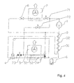
- Fig. 4 shows the in Fig. 1 illustrated air conditioning in the operating mode "drying and cooling".
- the refrigerant is compressed by the compressor 1.
- a part of the refrigerant flows via the valve 71, the outer heat exchanger 2 and the optional check valve 8, another part flows in parallel via the valve 72, the sub-string 51 of the inner heat exchanger 5 and the three-way valve 74 to the high-pressure part 31 of the internal heat exchanger 3 and on to the expansion element 4.
- the refrigerant is reduced in pressure and flows back via the sub-strand 52 of the inner heat exchanger 5, the collector 6 and the low-pressure part 32 of the internal heat exchanger 3 to the compressor 1.
- the refrigerant evaporates in the sub-strand 52 of the inner heat exchanger 5.
- the valve 73 and the three-way valve 74 block the sub-strand 51 of the inner heat exchanger 5 from the sub-strand 52 from.
- the air flowing through the inner heat exchanger 5 is first cooled by the partial heat exchanger 52 and thereby dehumidified and then reheated in the partial heat exchanger 51 by reheating.
- the air outlet temperature of the inner heat exchanger 5 can be controlled via targeted opening and closing of the valve 72.
- Fig. 5 shows the in Fig. 1 illustrated air conditioning in the operating mode "drying and heating".
- the refrigerant is removed from the compressor 1 compresses and flows via the valve 72, the sub-strand 51 of the inner heat exchanger 5 and the three-way valve 74 and the high-pressure part 31 of the internal heat exchanger 3 to the expansion element 4.
- the refrigerant is reduced in pressure and flows over the sub-string 52 of the inner heat exchanger 5, the collector 6 and the low pressure part 32 of the internal heat exchanger 3 to the compressor 1 back.
- the refrigerant evaporates in the sub-strand 52 of the inner heat exchanger 5.
- the valve 73 and the three-way valve 74 block the sub-strand 51 of the inner heat exchanger 5 from the sub-strand 52 from.
- the air flowing through the inner heat exchanger 5 is first cooled by the partial heat exchanger 52 and thereby dehumidified and then reheated in the partial heat exchanger 51 by reheating.
- the air outlet temperature of the inner heat exchanger 5 can be controlled by selectively opening and closing the valve 71, wherein a portion of the refrigerant parallel to the sub-strand 51 of the inner heat exchanger 5 via the valve 71, the outer heat exchanger 2 and the optional check valve 8 to the high-pressure part 31 of the internal Heat exchanger 3 flows.
- Fig. 6 shows the in Fig. 1 illustrated air conditioning in the operating mode "normal heating".
- the refrigerant is compressed by the compressor 1 and flows back through the valve 72, the sub-string 51 of the inner heat exchanger 5, the three-way valve 74, the collector 6 and the low pressure part 32 of the internal heat exchanger 3 to the compressor 1.
- the valves 71 and 73 remain closed in this mode.
- the outer heat exchanger 2, the high-pressure part 31 of the internal heat exchanger 3 and the sub-strand 52 of the inner heat exchanger 5 are not flowed through.
- An expansion of the refrigerant can take place, for example, by pulsed opening and closing of the valve 72.
- Fig. 7 shows the operating mode "maximum heating".
- the refrigerant is compressed by the compressor 1 and flows back through the valve 72, the inner heat exchanger 5, the collector 6 and the low-pressure part 32 of the internal heat exchanger 3 to the compressor 1.
- Part of the refrigerant flows via the sub-string 51 of the inner heat exchanger 5 and the three-way valve 74 to the collector 6, another part in parallel via the valve 73 and the sub-string 52 of the inner heat exchanger 5.
- the valve 71 remains closed in this mode and blocks the outer heat exchanger 2 and the high pressure part 31 of the internal heat exchanger 3 from.
- An expansion of the refrigerant can take place, for example, by pulsed opening and closing of the valve 72.
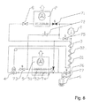
- Fig. 8 additionally shows a bypass between the high-pressure side and the low-pressure side of the compressor 1, bypassing the outer heat exchanger 2 and the inner heat exchanger 5.
- the bypass can be shut off via a valve 75.
- the opening of the valve 75 can be used to control a certain SauggasGermanhitzung the compressor inlet during the hot gas cycle ("maximum heating” or "normal heating") or to control a certain temperature or pressure levels on the compressor.
- the valve 75 is intended to prevent cooling of the compressor by liquid refrigerant at the compressor inlet.
- valves 76 and 77 are arranged in the suction line, here preferably at the inlet to the low pressure part 32 of the internal heat exchanger 3. These may also be located immediately in front of the compressor 1 or one of the valves 76, 77 in a bypass parallel to the low pressure part 32 of the internal heat exchanger 3. In the open state, the valves 76, 77 lead to no significant pressure loss in the operating modes "maximum cooling”, “normal cooling”, “drying and cooling” and “drying and heating”. In the operating modes "normal heating” or "maximum heating”, these are controlled as an expansion element.
- valves 76, 77 may have the same or different throttle characteristics. To control the suction gas superheat at the inlet of the compressor 1 or the compressor outlet temperature or the high pressure both valves 76, 77 can be opened or closed one depending on the compressor speed or mass flow. The mass flow of an unregulated compressor can be controlled in this way in all modes.
- valve 77 can also be replaced by a fixed throttle, wherein the control over the opening and closing of the other valve 76 takes place.
- the valve 77 may be a thermostatic expansion valve, which corrects the Sauggasüberhitzung the compressor inlet in the modes "maximum heating” and "normal heating". In these modes, the valve 76 is closed, open in all other modes. If the valve 76 is additionally controllable in order to regulate the suction gas superheat, the compressor outlet temperature, the high pressure or the mass flow, the valve 77 and the associated sub-string can also be dispensed with.
Landscapes
- Engineering & Computer Science (AREA)
- Mechanical Engineering (AREA)
- Physics & Mathematics (AREA)
- Thermal Sciences (AREA)
- General Engineering & Computer Science (AREA)
- Chemical & Material Sciences (AREA)
- Combustion & Propulsion (AREA)
- Air-Conditioning For Vehicles (AREA)
- Compression-Type Refrigeration Machines With Reversible Cycles (AREA)
- Central Air Conditioning (AREA)
- Sorption Type Refrigeration Machines (AREA)
- Air Filters, Heat-Exchange Apparatuses, And Housings Of Air-Conditioning Units (AREA)
Abstract
Description
- Die Erfindung betrifft eine Klimaanlage mit Heizfunktion, umfassend einen Kältemittelkreislauf mit einem Verdichter, einen äußeren Wärmetauscher, ein Expansionsorgan und einen inneren Wärmetauscher, wobei der innere Wärmetauscher in Luftströmungsrichtung in einen ersten und einen zweiten Wärmetauscherstrang geteilt ist.
- Eine derartige Klimaanlage für ein Kraftfahrzeug geht beispielsweise aus der
EP 888 912 B1 - Um gestiegenen Komfortanforderungen gerecht zu werden, ist es wünschenswert, eine derartige Klimaanlage mit möglichst geringem konstruktivem Aufwand um zusätzliche Betriebsarten zu erweitern.
- Diese Aufgabe wird erfindungsgemäß durch die Merkmale des Patentanspruchs 1 gelöst. Bevorzugte Weiterbildungen der Erfindung gehen aus den Unteransprüchen hervor.
- Die Klimaanlage mit Heizfunktion umfasst einen Kältemittelkreislauf mit einem Verdichter, einen äußeren Wärmetauscher, ein Expansionsorgan und einen inneren Wärmetauscher, wobei der innere Wärmetauscher in Luftströmungsrichtung in einen ersten und einen zweiten Wärmetauscherstrang geteilt ist. Erfindungsgemäß ist die Hochdruckseite des Verdichters über ein erstes Ventil mit dem äußeren Wärmetauscher und über ein zweites Ventil mit dem ersten Wärmetauscherstrang des inneren Wärmetauschers verbindbar, wobei dem äußeren Wärmetauscher ein Expansionsorgan nachgeschaltet ist, das über den zweiten Wärmetauscherstrang mit der Niederdruckseite des Verdichters in Verbindung steht, wobei das Expansionsorgan über ein drittes Ventil ferner mit dem ersten Wärmetauscherstrang des inneren Wärmetauschers verbindbar ist, und wobei mittels eines dem ersten Wärmetauscherstrang nachgeschalteten Dreiwegeventils eine Verbindung entweder mit der Niederdruckseite des Verdichters oder aber mit einer zwischen dem äußeren Wärmetauscher und dem Expansionsorgan vorgesehenen Abzweigung herstellbar ist.
- Die Klimaanlage ist derart konfiguriert, dass mit möglichst wenig Ventilen insgesamt sechs Betriebsarten realisiert werden können.
- So kann mittels der Ventile von der Betriebsart "Kühlen" in die Betriebsart "Heizen" umgeschaltet werden, wobei mittels des Kompressors auch geheizt wird. Durch den in Luftströmungsrichtung geteilten Aufbau des inneren Wärmetauschers kann zusätzlich ein Trocknen der Zuluft für den Innenraum erreicht werden. Dabei durchströmt die Zuluft erst den vorzugsweise als Verdampfer dienenden ersten Teilwärmetauscher, der dabei abgekühlt wird, so dass Luftfeuchtigkeit an den Lamellen der Wärmeaustauschfläche kondensiert. Im vorzugsweise als Gaskühler dienenden zweiten Teilwärmetauscher wird die Zuluft durch Rückheizen wieder erwärmt. Dieser innere Wärmetauscher, der als ein Bauteil des Kältemittelkreislaufs im Zuluftstrom des Fahrzeuginnenraums Verwendung findet, ist dabei kältemittelseitig in einen warmen und in einen kalten Teilwärmetauscher aufteilbar, wobei die luftseitige Wärmeaustauschfläche der beiden Teilwärmetauscher thermisch getrennt ist.
- Insbesondere bei verbrauchsoptimierten Verbrennungsmotoren steht eine ausreichende Abwärme im Kühlkreislauf des Motors während der Kaltstartphase nicht zur Verfügung. Der vom Verbrennungsmotor angetriebene Klimaverdichter liefert unmittelbar nach dem Start ausreichend Verdichterabwärme bei hohen Verdichteraustrittstemperaturen. Durch die direkte Wärmeübertragung im als Gaskühler wirkenden inneren Wärmetauscher können vergleichsweise hohe Zuluftausblastemperaturen erreicht werden, sodass unmittelbar nach dem Start die Fahrzeugscheiben von Eis und Beschlag freigeblasen werden können. Hierbei durchläuft das Kältemittel den Verdichter, den inneren Wärmetauscher, der als Gaskühler arbeitet, und gegebenenfalls ein vor dem Gaskühler angeordnetes Expansionsorgan.
- Für die maximale Heiz- bzw. Kühlleistung können die beiden Teilstränge des inneren Wärmetauschers parallel geschaltet werden. Beim direkten Umschalten von maximalem Kühlen in maximales Heizen können die Fahrzeugscheiben beschlagen. Der Grund dafür liegt darin, dass die an der zuvor gekühlten Wärmetauscherfläche des Verdampfers auskondensierte Luftfeuchtigkeit in der Arbeitsweise als Gaskühler sofort verdampfen kann und sich auf den kalten Fahrzeugscheiben niederschlägt. Um dies zu vermeiden, kann der in Luftströmungsrichtung erste Teilstrang des inneren Wärmetauschers auch ohne den zweiten Teilstrang in der Betriebsart "normales Kühlen" als Verdampfer betrieben werden. Dies ist vorzugsweise kurz vor Erreichen der Innenraumsolltemperatur der Fall. Ebenso kann der in Luftströmungsrichtung zweite Teilstrang des inneren Wärmetauschers auch ohne den ersten Teilstrang in der Betriebsart "normales Heizen" als Gaskühler betrieben werden. Die Wärmeaustauschflächen beider Teilstränge des inneren Wärmetauschers sind thermisch voneinander durch einen Luftspalt getrennt. Dies verhindert in der Betriebsart "normales Heizen", dass Wärme vom als Gaskühler betriebenen zweiten Teilwärmetauscher auf den zuvor als Verdampfer betriebenen ersten Teilwärmetauscher übertragen wird und eventuell auskondensierte Luftfeuchtigkeit wieder verdampfen kann. Ein ähnlicher Aufbau ist von herkömmlichen Fahrzeugklimaanlagen bekannt, wobei allerdings die Kühlflüssigkeit des Motors als Heizmedium verwendet wird. Zusätzlich kann die Zuluft in den Betriebsarten "Trocknen und Kühlen" bzw. "Trocknen und Heizen" durch das oben beschriebene Rückheizen getrocknet werden, was dem Beschlagen der Fahrzeugscheiben entgegenwirkt.
- Typischerweise wird die Klimaanlage zur schnellen Abkühlung des im Sommer stark aufgeheizten Fahrzeuginnenraums zunächst in der Betriebsart "maximales Kühlen" betrieben, in dem beide Teilstränge des inneren Wärmetauschers als Verdampfer arbeiten. Kurz vor Erreichen der Solltemperatur wird in die Betriebsart "normales Kühlen" geschaltet, in der nur der erste Teilstrang (ohne den zweiten Teilstrang) des inneren Wärmetauschers als Verdampfer arbeitet. Bei Erreichen der Solltemperatur wird die Temperatur beispielsweise durch gezieltes Gegenheizen mit dem zweiten Teilstrang des inneren Wärmetauschers als Gaskühler ausgeregelt. Der zweite Teilstrang erwärmt sich dabei. Dadurch wird die Zuluft getrocknet. Eventuell vorhandene Restfeuchte dieses in der Betriebsart "maximales Kühlen" als Verdampfer betriebenen Teilwärmetauschers kann zwar verdampfen, wird sich aber nicht an den Fahrzeugscheiben niederschlagen können, da diese im Sommer durch die Außenluft und eventuell durch Sonneneinstrahlung wärmer sind als die gekühlte Zuluft.
- Im Gegensatz zum Rückheizen mit Motorkühlwasser ist der erfindungsgemäße Klimaanlagenbetrieb in der Betriebsart "Trocknen und Kühlen" effizienter. Das Temperaturniveau im zusätzlich als Gaskühler bzw. Kondensator betriebenen zweiten Teilstrang des inneren Wärmetauschers ist deutlich geringer als das Temperaturniveau im äußeren Wärmetauscher. Der Hochdruck der Klimaanlage kann dadurch abgesenkt werden. Die geringere Druckdifferenz und das geringere Druckverhältnis wirken sich vorteilhaft auf die Verdichtereffizienz aus. Erfindungsgemäß wird weniger Verdichtungsarbeit benötigt, weil die Enthalpiedifferenz zwischen Verdichteraustritt und -eintritt abnimmt. Dies wirkt sich auch vorteilhaft in einer geringeren mechanischen und thermischen Belastung des Verdichters aus. Durch die erfindungsgemäße Absenkung der Kältemitteleintrittstemperatur in das Expansionsorgan wird die Enthalpiedifferenz zwischen Verdampferaustritt und Verdampfereintritt vorteilhaft gesteigert. Die Klimaanlageneffizienz als Verhältnis der Verdampferleistung bzw. Verdampferenthalpiedifferenz zur Verdichterarbeit bzw. Verdichterenthalpiedifferenz nimmt zu.
- Typischerweise wird die Klimaanlage mit Heizfunktion zur schnellen Aufheizung des in kalten Wintern erheblich ausgekühlten Fahrzeuginnenraums zunächst in der Betriebsart "maximales Heizen" betrieben, in der beide Teilstränge des inneren Wärmetauschers als Gaskühler arbeiten. Bei plötzlichem Beschlagen der Fahrzeugscheiben wird die Klimaanlage in die Betriebsart "normales Heizen" geschaltet, in der nur der zweite Teilstrang (ohne den ersten Teilstrang) des inneren Wärmetauschers als Gaskühler arbeitet.
- Die Betriebsarten "maximales Heizen" und "normales Heizen" sind sogenannte Heißgas- oder Dreiecksprozesse, wie oben beschrieben. Auch die dritte Betriebsart "Trocknen und Heizen" ist kein Wärmepumpenprozess, obwohl das Kältemittel im zweiten Teilstrang des inneren Wärmetauschers gekühlt und im ersten Teilstrang verdampft wird. Die Zuluft zum Fahrzeuginnenraum dient sowohl als Wärmequelle (im ersten Teilwärmetauscher) als auch als Wärmesenke (im zweiten Teilwärmetauscher). Wie in den beiden anderen Betriebsarten stellt die Verdichterabwärme einen großen Teil der eingebrachten Wärmemenge. Gegenüber dem reinen Heißgaszyklus hat die erfindungsgemäße Betriebsart "Trocknen und Heizen" den Vorteil, die latente Wärme der kondensierbaren Zuluftfeuchtigkeit zusätzlich zur Verdichterabwärme zu nutzen. Ein weiterer Vorteil dieser Betriebsart ist ein schnelleres Befreien der Fahrzeugscheiben von Eis und Beschlag durch die getrocknete und aufgeheizte Zuluft. Bei eventuell auftretender Vereisung des als Verdampfer arbeitenden ersten Teilstrangs des inneren Wärmetauschers, was mittels eines Vereisungsschutzes, beispielsweise eines Temperatursensors detektiert wird, wird vorzugsweise in die Betriebsart "normales Heizen" umgeschaltet. Dies ist ein Heißgaszyklus, bei dem der erste Teilstrang des inneren Wärmetauschers nicht vom Kältemittel durchströmt wird. Wenn der erste Teilstrang durch die Zuluft, die einen Anteil erwärmter Rückluft aus dem Fahrzeuginnenraum enthält, abgetaut ist, kann erneut in die Betriebsart "Trocknen und Heizen" geschaltet werden.
- Erreicht die Motorkühlwassertemperatur einen bestimmten Sollwert, vorzugsweise einen Wert größer als die Zuluftausblastemperatur, oder wird der Sollwert der Luftinnenraumtemperatur erreicht, übernimmt das erwärmte Motorkühlwasser im Heizungswärmetauscher, der vorzugsweise in Luftströmungsrichtung dem inneren Wärmetauscher des Kältemittelkreislaufs nachgeordnet ist, die Beheizung der Zuluft. Der Verdichter der Klimaanlage wird abgeschaltet, oder es wird zum Rückheizen die Klimaanlage in die Betriebsart "normales Kühlen" geschaltet. Die Wärmeabgabe erfolgt dabei über den äußeren Wärmetauscher an die Außenluft, die in diesem Fall typischerweise kälter als die Zuluft ist. Ein Beheizen des Fahrzeugs mit Motorkühlwasserabwärme ist energetisch vorteilhafter, als den Kältemittelverdichter zur Beheizung dauerhaft durch den Motor anzutreiben. Andererseits steht während der Kaltstartphase des Motors diese Abwärme nicht ausreichend zur Verfügung, und es ist energetisch sinnvoller, den Kältemittelverdichter anzutreiben, als die Lichtmaschine als Generator anzutreiben und beispielsweise mittels eines PTC elektrisch zu heizen, da der Wirkungsgrad bei der Wandlung mechanischer Antriebsenergie in elektrische Energie im Allgemeinen schlechter ist.
- Weitere Einzelheiten, Merkmale und Vorteile ergeben sich aus der nachfolgenden Beschreibung der anliegenden Zeichnungen. Es zeigen:
- Fig. 1
- ein schematisch dargestelltes Ausführungsbeispiel der erfindungsgemäßen Klimaanlage,
- Fig. 2
- das gemäß
Fig. 1 dargestellte Ausführungsbeispiel der erfindungsgemäßen Klimaanlage in einer Betriebsart "maximales Kühlen", - Fig. 3
- das gemäß
Fig. 1 dargestellte Ausführungsbeispiel der erfindungsgemäßen Klimaanlage in einer Betriebsart "normales Kühlen", - Fig. 4
- das gemäß
Fig. 1 dargestellte Ausführungsbeispiel der erfindungsgemäßen Klimaanlage in einer Betriebsart "Trocknen und Kühlen", - Fig. 5
- das gemäß
Fig. 1 dargestellte Ausführungsbeispiel der erfindungsgemäßen Klimaanlage in einer Betriebsart "Trocknen und Heizen", - Fig. 6
- das gemäß
Fig. 1 dargestellte Ausführungsbeispiel der erfindungsgemäßen Klimaanlage in einer Betriebsart "normales Heizen", - Fig. 7
- das gemäß
Fig. 1 dargestellte Ausführungsbeispiel der erfindungsgemäßen Klimaanlage in einer Betriebsart "maximales Heizen", und - Fig. 8
- das gemäß
Fig. 1 dargestellte Ausführungsbeispiel der erfindungsgemäßen Klimaanlage mit einem zusätzlichen Verdichterbypass. -
Fig. 1 zeigt eine Klimaanlage mit Heizfunktion, die mittels Umschaltventilen 71, 72, 73 und 74 sechs unterschiedliche Betriebsarten vorsieht. Ein innerer Wärmetauscher 5 für den Fahrzeuginnenraum ist in Luftströmungsrichtung geteilt. Die Luft durchströmt zunächst einen vorzugsweise zum Kühlen eingesetzten Teilwärmetauscher 52 und danach einen vorzugsweise zum Heizen eingesetzten Teilwärmetauscher 51. Hinter diesem inneren Wärmetauscher 5 kann in Luftströmungsrichtung zusätzlich ein Heizungswärmetauscher angeordnet sein, der die Luft mittels warmen Motorkühlwassers erwärmt. Die Wärmetauscher 2 und 5 und die Umschaltventile 71 bis 74 sind derart angeordnet, dass mit möglichst geringem konstruktivem Aufwand die sechs Betriebsarten realisiert werden können. Die Teilwärmetauscher 51 und 52 sind in den Betriebsarten "maximales Kühlen" und "maximales Heizen" jeweils parallel geschaltet. In den Betriebsarten "normales Kühlen" und "normales Heizen" wird nur jeweils ein Teilwärmetauscher von Kältemittel durchströmt. In der Betriebsart "Trocknen" wird der Teilwärmetauscher 51 mit Hochdruck und der Teilwärmetauscher 52 mit Niederdruck vom Kältemittel durchströmt. Ein Rückschlagventil 8, ein interner Wärmetauscher 3 und ein Sammler 6 sind optionale Bauteile. -
Fig. 2 zeigt die inFig. 1 dargestellte Klimaanlage in der Betriebsart "maximales Kühlen". Das Kältemittel wird vom Verdichter 1 komprimiert und strömt über das Ventil 71, den äußeren Wärmetauscher 2, das optionale Rückschlagventil 8 und den Hochdruckteil 31 des internen Wärmetauschers 3 zum Expansionsorgan 4. Im Expansionsorgan 4 wird das Kältemittel im Druck reduziert und strömt über den inneren Wärmetauscher 5, den Sammler 6 und den Niederdruckteil 32 des internen Wärmetauschers 3 zum Verdichter 1 zurück. Das Kältemittel verdampft dabei im inneren Wärmetauscher 5, wobei ein Teil durch den Teilstrang 52 und ein anderer Teil parallel dazu durch das Ventil 73, den Teilstrang 51 und das Dreiwegeventil 74 strömt. Das Ventil 72 bleibt in dieser Betriebsart geschlossen. -
Fig. 3 zeigt die inFig. 1 dargestellte Klimaanlage in der Betriebsart "normales Kühlen". Das Kältemittel wird vom Verdichter 1 komprimiert und strömt über das Ventil 71, den äußeren Wärmetauscher 2, das optionale Rückschlagventil 8 und den Hochdruckteil 31 des internen Wärmetauschers 3 zum Expansionsorgan 4. Im Expansionsorgan 4 wird das Kältemittel im Druck reduziert und strömt über den inneren Wärmetauscher 5, den Sammler 6 und den Niederdruckteil 32 des internen Wärmetauschers 3 zum Verdichter 1 zurück. Das Kältemittel verdampft dabei im inneren Wärmetauscher 5, wobei das gesamte Kältemittel nur durch den Teilstrang 52 strömt. Die Ventile 72 und 73 bleiben in dieser Betriebsart geschlossen und das Dreiwegeventil 74 sperrt den Teilstrang 51 des inneren Wärmetauschers 5 vom Teilstrang 52 ab. -
Fig. 4 zeigt die inFig. 1 dargestellte Klimaanlage in der Betriebsart "Trocknen und Kühlen". Das Kältemittel wird vom Verdichter 1 komprimiert. Ein Teil des Kältemittels strömt über das Ventil 71, den äußeren Wärmetauscher 2 und das optionale Rückschlagventil 8, ein anderer Teil strömt parallel dazu über das Ventil 72, den Teilstrang 51 des inneren Wärmetauschers 5 und das Dreiwegeventil 74 zum Hochdruckteil 31 des internen Wärmetauschers 3 und weiter zum Expansionsorgan 4. Im Expansionsorgan 4 wird das Kältemittel im Druck reduziert und strömt über den Teilstrang 52 des inneren Wärmetauschers 5, den Sammler 6 und den Niederdruckteil 32 des internen Wärmetauschers 3 zum Verdichter 1 zurück. Das Kältemittel verdampft dabei im Teilstrang 52 des inneren Wärmetauschers 5. Das Ventil 73 und das Dreiwegeventil 74 sperren den Teilstrang 51 des inneren Wärmetauschers 5 vom Teilstrang 52 ab. Die Luft, die den inneren Wärmetauscher 5 durchströmt, wird zunächst durch den Teilwärmetauscher 52 abgekühlt und dabei entfeuchtet und anschließend im Teilwärmetauscher 51 durch Rückheizen wieder erwärmt. Die Luftaustrittstemperatur des inneren Wärmetauschers 5 kann über gezieltes Öffnen und Schließen des Ventils 72 geregelt werden. -
Fig. 5 zeigt die inFig. 1 dargestellte Klimaanlage in der Betriebsart "Trocknen und Heizen". Das Kältemittel wird vom Verdichter 1 komprimiert und strömt über das Ventil 72, den Teilstrang 51 des inneren Wärmetauschers 5 und das Dreiwegeventil 74 und den Hochdruckteil 31 des internen Wärmetauschers 3 zum Expansionsorgan 4. Im Expansionsorgan 4 wird das Kältemittel im Druck reduziert und strömt über den Teilstrang 52 des inneren Wärmetauschers 5, den Sammler 6 und den Niederdruckteil 32 des internen Wärmetauschers 3 zum Verdichter 1 zurück. Das Kältemittel verdampft dabei im Teilstrang 52 des inneren Wärmetauschers 5. Das Ventil 73 und das Dreiwegeventil 74 sperren den Teilstrang 51 des inneren Wärmetauschers 5 vom Teilstrang 52 ab. Die Luft, die den inneren Wärmetauscher 5 durchströmt, wird zunächst durch den Teilwärmetauscher 52 abgekühlt und dabei entfeuchtet und anschließend im Teilwärmetauscher 51 durch Rückheizen wieder erwärmt. Die Luftaustrittstemperatur des inneren Wärmetauschers 5 kann über gezieltes Öffnen und Schließen des Ventils 71 geregelt werden, wobei ein Teil des Kältemittels parallel zum Teilstrang 51 des inneren Wärmetauschers 5 über das Ventil 71, den äußeren Wärmetauscher 2 und das optionale Rückschlagventil 8 zum Hochdruckteil 31 des internen Wärmetauschers 3 strömt. -
Fig. 6 zeigt die inFig. 1 dargestellte Klimaanlage in der Betriebsart "normales Heizen". Das Kältemittel wird vom Verdichter 1 komprimiert und strömt über das Ventil 72, den Teilstrang 51 des inneren Wärmetauschers 5, das Dreiwegeventil 74, den Sammler 6 und den Niederdruckteil 32 des internen Wärmetauschers 3 zum Verdichter 1 zurück. Die Ventile 71 und 73 bleiben in dieser Betriebsart geschlossen. Der äußere Wärmetauscher 2, der Hochdruckteil 31 des internen Wärmetauschers 3 und der Teilstrang 52 des inneren Wärmetauschers 5 werden nicht durchströmt. Eine Expansion des Kältemittels kann beispielsweise durch gepulstes Öffnen und Schließen des Ventils 72 erfolgen. -
Fig. 7 zeigt die Betriebsart "maximales Heizen". Das Kältemittel wird vom Verdichter 1 komprimiert und strömt über das Ventil 72, den inneren Wärmetauscher 5, den Sammler 6 und den Niederdruckteil 32 des internen Wärmetauschers 3 zum Verdichter 1 zurück. Ein Teil des Kältemittels strömt über den Teilstrang 51 des inneren Wärmetauschers 5 und das Dreiwegeventil 74 zum Sammler 6, ein anderer Teil parallel dazu über das Ventil 73 und den Teilstrang 52 des inneren Wärmetauschers 5. Das Ventil 71 bleibt in dieser Betriebsart geschlossen und sperrt den äußeren Wärmetauscher 2 und den Hochdruckteil 31 des internen Wärmetauschers 3 ab. Eine Expansion des Kältemittels kann beispielsweise durch gepulstes Öffnen und Schließen des Ventils 72 erfolgen. -
Fig. 8 zeigt zusätzlich einen Bypass zwischen der Hochdruckseite und der Niederdruckseite des Verdichters 1 unter Umgehung des äußeren Wärmetauschers 2 und des inneren Wärmetauschers 5. Der Bypass ist über ein Ventil 75 absperrbar. Die Öffnung des Ventils 75 kann zur Regelung einer bestimmten Sauggasüberhitzung am Verdichtereintritt während des Heißgaszyklus ("maximales Heizen" bzw. "normales Heizen") oder auch zur Regelung eines bestimmten Temperatur- oder Druckniveaus am Verdichter eingesetzt werden. Das Ventil 75 soll eine Kühlung des Verdichters durch flüssiges Kältemittel am Verdichtereintritt verhindern. - Ferner sind parallele Ventile 76 und 77 in der Saugleitung angeordnet, hier vorzugsweise am Eintritt in den Niederdruckteil 32 des internen Wärmetauschers 3. Diese können auch unmittelbar vor dem Verdichter 1 angeordnet sein oder eines der Ventile 76, 77 in einem Bypass parallel zum Niederdruckteil 32 des internen Wärmetauschers 3. In geöffnetem Zustand führen die Ventile 76, 77 zu keinem wesentlichen Druckverlust in den Betriebsarten "maximales Kühlen", "normales Kühlen", "Trocknen und Kühlen" und "Trocknen und Heizen". In den Betriebsarten "normales Heizen" bzw. "maximales Heizen" werden diese als Expansionsorgan angesteuert.
- Dabei können die Ventile 76, 77 gleiche oder unterschiedliche Drosselkennlinien haben. Zur Regelung der Sauggasüberhitzung am Eintritt des Verdichters 1 oder der Verdichteraustrittstemperatur bzw. des Hochdruckes können beide Ventile 76, 77 geöffnet oder jeweils eines geschlossen sein je nach Verdichterdrehzahl bzw. Massenstrom. Der Massenstrom eines ungeregelten Verdichters kann auf diese Weise in allen Betriebsarten geregelt werden.
- Eines der Ventile, beispielsweise das Ventil 77, kann auch durch eine Fixdrossel ersetzt werden, wobei die Regelung über das Öffnen und Schließen des anderen Ventils 76 erfolgt. Sofern das Ventil 76 keinen nennenswerten Druckverlust in vollständig geöffnetem Zustand aufweist, kann das Ventil 77 ein thermostatisches Expansionsventil sein, das die Sauggasüberhitzung am Verdichtereintritt in den Betriebsarten "maximales Heizen" und "normales Heizen" ausregelt. In diesen Betriebsarten ist das Ventil 76 geschlossen, in allen anderen Betriebsarten geöffnet. Sofern das Ventil 76 zusätzlich ansteuerbar ist, um die Sauggasüberhitzung, die Verdichteraustrittstemperatur, den Hochdruck oder den Massenstrom zu regeln, kann das Ventil 77 und der dazugehörende Teilstrang auch entfallen.
Claims (15)
- Klimaanlage mit Heizfunktion, umfassend einen Kältemittelkreislauf mit einem Verdichter (1), einen äußeren Wärmetauscher (2), ein Expansionsorgan (4) und einen inneren Wärmetauscher (5), wobei der innere Wärmetauscher (5) in Luftströmungsrichtung in einen ersten und einen zweiten Wärmetauscherstrang (51, 52) geteilt ist, dadurch gekennzeichnet, dass die Hochdruckseite des Verdichters (1) über ein erstes Ventil (71) mit dem äußeren Wärmetauscher (2) und über ein zweites Ventil (72) mit dem ersten Wärmetauscherstrang (52) des inneren Wärmetauschers (5) verbindbar ist, wobei dem äußeren Wärmetauscher (2) ein Expansionsorgan (4) nachgeschaltet ist, das über den zweiten Wärmetauscherstrang (52) mit der Niederdruckseite des Verdichters (1) in Verbindung steht, wobei das Expansionsorgan (4) über ein drittes Ventil (73) ferner mit dem ersten Wärmetauscherstrang (51) des inneren Wärmetauschers (5) verbindbar ist, und wobei mittels eines dem ersten Wärmetauscherstrang (51) nachgeschalteten Dreiwegeventils (74) eine Verbindung entweder mit der Niederdruckseite des Verdichters (1) oder aber mit einer zwischen dem äußeren Wärmetauscher (2) und dem Expansionsorgan (4) vorgesehenen Abzweigung herstellbar ist.
- Klimaanlage nach Anspruch 1, dadurch gekennzeichnet, dass dem inneren Wärmetauscher (5) in Luftströmungsrichtung ein zusätzlicher Heizungswärmetauscher nachgeschaltet ist.
- Klimaanlage nach Anspruch 1 oder 2, dadurch gekennzeichnet, dass ein interner Wärmetauscher (3) mit einem Hochdruckteil (31) und einem Niederdruckteil (32) vorgesehen ist, wobei der Hochdruckteil (31) zwischen dem äußeren Wärmetauscher (2) und dem Expansionsorgan (4) und der Niederdruckteil (32) zwischen dem zweiten Wärmetauscherstrang (52) des inneren Wärmetauschers (5) und der Niederdruckseite des Verdichters (1) vorgesehen ist.
- Klimaanlage nach Anspruch 3, dadurch gekennzeichnet, dass zwischen dem äußeren Wärmetauscher (2) und dem Hochdruckteil (31) des internen Wärmetauschers (3) ein Rückschlagventil (8) vorgesehen ist.
- Klimaanlage nach Anspruch 3 oder 4, dadurch gekennzeichnet, dass zwischen dem zweiten Wärmetauscherstrang (52) des inneren Wärmetauschers (5) und dem Niederdruckteil (32) ein Sammler (6) vorgesehen ist.
- Klimaanlage nach einem der Ansprüche 1 bis 5, dadurch gekennzeichnet, dass ein durch ein fünftes Ventil (75) gebildeter Bypass zwischen der Hochdruckseite und der Niederdruckseite des Verdichters (1) vorgesehen ist.
- Klimaanlage nach einem der Ansprüche 1 bis 6, dadurch gekennzeichnet, dass zwischen dem inneren Wärmetauscher (5) und der Niederdruckseite des Verdichters (1) ein Paar parallel geschalteter Ventile (76, 77) vorgesehen sind.
- Klimaanlage nach Anspruch 7, dadurch gekennzeichnet, dass die Ventile (76, 77) gleiche oder unterschiedliche Drosselkennlinien aufweisen.
- Klimaanlage nach Anspruch 7 oder 8, dadurch gekennzeichnet, dass es sich bei einem der Ventile (76, 77) um eine Fixdrossel handelt.
- Klimaanlage nach einem der Ansprüche 1 bis 9, dadurch gekennzeichnet, dass in einer auf maximales Kühlen gerichteten Betriebsart das erste und dritte Ventil (71, 73) geöffnet sowie das zweite Ventil (72) geschlossen ist, und dass mittels des Dreiwegeventils (74) eine Verbindung des ersten Wärmetauscherstrangs (51) mit der Niederdruckseite des Verdichters (1) hergestellt ist.
- Klimaanlage nach einem der Ansprüche 1 bis 9, dadurch gekennzeichnet, dass in einer auf normales Kühlen gerichteten Betriebsart das erste Ventil (71) geöffnet sowie das zweite und dritte Ventil (72, 73) geschlossen ist, und dass mittels des Dreiwegeventils (74) eine Verbindung des ersten Wärmetauscherstrangs (51) mit der zwischen dem äußeren Wärmetauscher (2) und dem Expansionsorgan (4) vorgesehenen Abzweigung hergestellt ist.
- Klimaanlage nach einem der Ansprüche 1 bis 9, dadurch gekennzeichnet, dass in einer auf Trocknen und Kühlen gerichteten Betriebsart das erste und zweite Ventil (71, 72) geöffnet sowie das dritte Ventil (72, 73) geschlossen ist, und dass mittels des Dreiwegeventils (74) eine Verbindung des ersten Wärmetauscherstrangs (51) mit der zwischen dem äußeren Wärmetauscher (2) und dem Expansionsorgan (4) vorgesehenen Abzweigung hergestellt ist.
- Klimaanlage nach einem der Ansprüche 1 bis 9, dadurch gekennzeichnet, dass in einer auf Trocknen und Heizen gerichteten Betriebsart das erste und dritte Ventil (71, 73) geschlossen sowie das zweite Ventil (72) geöffnet ist, und dass mittels des Dreiwegeventils (74) eine Verbindung des ersten Wärmetauscherstrangs (51) mit der zwischen dem äußeren Wärmetauscher (2) und dem Expansionsorgan (4) vorgesehenen Abzweigung hergestellt ist.
- Klimaanlage nach einem der Ansprüche 1 bis 9, dadurch gekennzeichnet, dass in einer auf normales Heizen gerichteten Betriebsart das erste und dritte Ventil (71, 73) geschlossen sowie das zweite Ventil (72) geöffnet ist, und dass mittels des Dreiwegeventils (74) eine Verbindung des ersten Wärmetauscherstrangs (51) mit der Niederdruckseite des Verdichters (1) hergestellt ist.
- Klimaanlage nach einem der Ansprüche 1 bis 9, dadurch gekennzeichnet, dass in einer auf maximales Heizen gerichteten Betriebsart das erste Ventil (71) geschlossen sowie das zweite und dritte Ventil (72, 73) geöffnet ist, und dass mittels des Dreiwegeventils (74) eine Verbindung des ersten Wärmetauscherstrangs (51) mit der Niederdruckseite des Verdichters (1) hergestellt ist.
Applications Claiming Priority (3)
| Application Number | Priority Date | Filing Date | Title |
|---|---|---|---|
| DE102006012709 | 2006-03-17 | ||
| DE102006024796A DE102006024796B4 (de) | 2006-03-17 | 2006-05-27 | Klimaanlage |
| EP07727024A EP1998966A2 (de) | 2006-03-17 | 2007-03-16 | Klimaanlage |
Related Parent Applications (2)
| Application Number | Title | Priority Date | Filing Date |
|---|---|---|---|
| EP07727024.7 Division | 2007-03-16 | ||
| EP07727024A Division EP1998966A2 (de) | 2006-03-17 | 2007-03-16 | Klimaanlage |
Publications (4)
| Publication Number | Publication Date |
|---|---|
| EP2093083A2 true EP2093083A2 (de) | 2009-08-26 |
| EP2093083A3 EP2093083A3 (de) | 2009-10-07 |
| EP2093083B1 EP2093083B1 (de) | 2010-10-27 |
| EP2093083B8 EP2093083B8 (de) | 2010-12-22 |
Family
ID=38375021
Family Applications (2)
| Application Number | Title | Priority Date | Filing Date |
|---|---|---|---|
| EP07727024A Withdrawn EP1998966A2 (de) | 2006-03-17 | 2007-03-16 | Klimaanlage |
| EP09162867A Not-in-force EP2093083B8 (de) | 2006-03-17 | 2007-03-16 | Klimaanlage |
Family Applications Before (1)
| Application Number | Title | Priority Date | Filing Date |
|---|---|---|---|
| EP07727024A Withdrawn EP1998966A2 (de) | 2006-03-17 | 2007-03-16 | Klimaanlage |
Country Status (6)
| Country | Link |
|---|---|
| US (1) | US20090095005A1 (de) |
| EP (2) | EP1998966A2 (de) |
| AT (1) | ATE485956T1 (de) |
| DE (2) | DE102006024796B4 (de) |
| FR (1) | FR2898544A1 (de) |
| WO (1) | WO2007107535A1 (de) |
Families Citing this family (30)
| Publication number | Priority date | Publication date | Assignee | Title |
|---|---|---|---|---|
| DE102007043161B4 (de) | 2006-09-14 | 2017-03-30 | Konvekta Ag | Klimaanlage für ein Fahrzeug |
| DE102008019044A1 (de) | 2008-04-16 | 2009-10-29 | Bayerische Motoren Werke Aktiengesellschaft | Kältemittelkreislauf für Fahrzeugklimaanlagen |
| SE533005C2 (sv) * | 2008-10-21 | 2010-06-08 | Scania Cv Abp | Metod och system för kylning och uppvärmning |
| KR101598624B1 (ko) | 2008-11-10 | 2016-02-29 | 엘지전자 주식회사 | 공기 조화 시스템 |
| WO2010082325A1 (ja) * | 2009-01-15 | 2010-07-22 | 三菱電機株式会社 | 空気調和装置 |
| DE102009028522B4 (de) * | 2009-08-13 | 2017-05-11 | Hanon Systems | Kompakte Klimaanlage für ein Kraftfahrzeug |
| FR2958018A1 (fr) * | 2010-03-24 | 2011-09-30 | Valeo Systemes Thermiques | Boucle de chauffage, ventilation et/ou climatisation et installation de chauffage, ventilation et/ou climatisation comprenant une telle boucle de chauffage, ventilation et/ou climatisation |
| WO2012014345A1 (ja) * | 2010-07-29 | 2012-02-02 | 三菱電機株式会社 | ヒートポンプ |
| US8973382B2 (en) * | 2012-04-17 | 2015-03-10 | Lee Wa Wong | Energy efficient air heating, air conditioning and water heating system |
| EP2906881A4 (de) * | 2012-05-11 | 2016-04-13 | Hill Phoenix Inc | Co2-kühlsystem mit integriertem klimatisierungsmodul |
| US9522589B2 (en) * | 2012-10-05 | 2016-12-20 | GM Global Technology Operations LLC | Vehicular heat pump system and control method |
| DE102014203895B4 (de) * | 2014-03-04 | 2018-08-16 | Konvekta Ag | Kälteanlage |
| US10317112B2 (en) * | 2014-04-04 | 2019-06-11 | Johnson Controls Technology Company | Heat pump system with multiple operating modes |
| US20160010904A1 (en) * | 2014-07-10 | 2016-01-14 | Systèmes Lmp Inc. | Transcritical r744 refrigeration system with gas cooler outlet vapors used as a heat source for the dehumidifying coil |
| US9863671B2 (en) | 2014-07-29 | 2018-01-09 | Ford Global Technologies, Llc | Heat pump assisted engine cooling for electrified vehicles |
| JP6323489B2 (ja) * | 2015-08-04 | 2018-05-16 | 株式会社デンソー | ヒートポンプシステム |
| DE102016110443B4 (de) * | 2016-06-06 | 2018-03-29 | Konvekta Aktiengesellschaft | Kälteanlage, Kälteanlagensystem und Verfahren mit Kältemittelverlagerung |
| US10214078B2 (en) * | 2016-10-20 | 2019-02-26 | Toyota Motor Engineering & Manufacturing North America, Inc. | AC cut cycles for vehicle air conditioning control based on high ambient temperature |
| DE102017213973B4 (de) | 2017-08-10 | 2020-06-04 | Audi Ag | Verfahren zum Betreiben einer Kälteanlage eines Fahrzeugs mit einem eine Kühl- und Heizfunktion aufweisenden Kältemittelkreislauf |
| KR102436655B1 (ko) | 2017-09-22 | 2022-08-26 | 삼성디스플레이 주식회사 | 표시 장치 |
| DE102017218424B4 (de) | 2017-10-16 | 2025-07-10 | Audi Ag | Verfahren zum Betreiben eines Kältemittelkreislaufs sowie Fahrzeugkälteanlage |
| US11221151B2 (en) * | 2019-01-15 | 2022-01-11 | Johnson Controls Technology Company | Hot gas reheat systems and methods |
| US10935290B2 (en) * | 2019-02-27 | 2021-03-02 | Rheem Manufacturing Company | Pressure spike prevention in heat pump systems |
| US20220099313A1 (en) | 2020-09-25 | 2022-03-31 | Emerson Climate Technologies, Inc. | Systems and methods for a refrigerant sub-system for a heating, ventilation, and air conditioning system |
| DE102020125249A1 (de) | 2020-09-28 | 2022-03-31 | Audi Aktiengesellschaft | Verfahren zum Betreiben einer Kälteanlage im Kühlbetrieb, Kälteanlage und Kraftfahrzeug mit einer solchen Kälteanlage |
| KR102462774B1 (ko) * | 2020-12-17 | 2022-11-02 | 엘지전자 주식회사 | 공기조화기 |
| CN113071289B (zh) * | 2021-04-28 | 2024-05-10 | 蔚来汽车科技(安徽)有限公司 | 一种电动汽车座舱加热系统及其控制方法 |
| KR102916849B1 (ko) * | 2021-05-04 | 2026-01-22 | 현대자동차주식회사 | 차량의 냉난방 시스템 |
| KR102765014B1 (ko) * | 2022-08-29 | 2025-02-12 | 엘지전자 주식회사 | 공기조화기 |
| US12337371B1 (en) | 2023-12-20 | 2025-06-24 | Copeland Lp | Systems and methods for assembling liquid desiccant air conditioner panels using flexible alignment features |
Citations (1)
| Publication number | Priority date | Publication date | Assignee | Title |
|---|---|---|---|---|
| EP0888912B1 (de) | 1997-06-30 | 2004-05-06 | Calsonic Kansei Corporation | Fahrzeugklimaanlage |
Family Cites Families (19)
| Publication number | Priority date | Publication date | Assignee | Title |
|---|---|---|---|---|
| US2940281A (en) * | 1958-11-25 | 1960-06-14 | Westinghouse Electric Corp | Air conditioning apparatus with provision for selective reheating |
| JPS57202462A (en) * | 1981-06-05 | 1982-12-11 | Mitsubishi Electric Corp | Air conditioner |
| US4688390A (en) * | 1986-05-27 | 1987-08-25 | American Standard Inc. | Refrigerant control for multiple heat exchangers |
| JP2936960B2 (ja) * | 1993-06-14 | 1999-08-23 | 日産自動車株式会社 | 車両用ヒートポンプ式冷暖房装置 |
| FR2735425B1 (fr) * | 1995-06-13 | 1997-07-18 | Valeo Climatisation | Dispositif de chauffage et/ou de climatisation de l'habitacle d'un vehicule automobile |
| JPH10100662A (ja) * | 1996-09-25 | 1998-04-21 | Calsonic Corp | 自動車用空気調和装置 |
| DE19813673B4 (de) | 1998-03-27 | 2004-01-29 | Daimlerchrysler Ag | Verfahren und Vorrichtung zum Heizen und Kühlen eines Nutzraumes eines Kraftfahrzeuges |
| FR2779216B1 (fr) * | 1998-05-28 | 2000-08-04 | Valeo Climatisation | Dispositif de climatisation de vehicule utilisant un fluide refrigerant a l'etat supercritique |
| DE10036038B4 (de) | 2000-07-25 | 2017-01-05 | Mahle International Gmbh | Verfahren zum Betrieb einer Klimaanlage eines Kraftfahrzeuges |
| DE10126257A1 (de) * | 2001-05-29 | 2002-12-05 | Behr Gmbh & Co | Heiz-/Kühlkreislauf für eine Klimaanlage eines Kraftfahrzeuges, Klimaanlage und Verfahren zur Regelung derselben |
| DE10149187A1 (de) | 2001-10-05 | 2003-04-17 | Bayerische Motoren Werke Ag | Klimaanlage für Kraftfahrzeuge mit einem von Kühlen auf Heizen umschaltbaren Kältemittelkreislauf |
| DE10203293A1 (de) | 2002-01-29 | 2003-07-31 | Audi Ag | Klimaanlage |
| DE10253357B4 (de) * | 2002-11-13 | 2006-05-18 | Visteon Global Technologies, Inc., Dearborn | Kombinierte Kälteanlage/Wärmepumpe zum Einsatz in Kraftfahrzeugen zum Kühlen, Heizen und Entfeuchten des Fahrzeuginnenraumes |
| US20060248906A1 (en) * | 2002-12-20 | 2006-11-09 | Behr Gmbh & Co. Kg | Air conditioning system for a vehicle and associated operating method |
| DE10318007B4 (de) * | 2003-04-22 | 2015-12-10 | Bayerische Motoren Werke Aktiengesellschaft | Heiz-/Klimaanlage für Fahrzeuge |
| DE10334907A1 (de) * | 2003-07-29 | 2005-03-10 | Bosch Gmbh Robert | Klimaanlage sowie Verfahren zum Betrieb einer Klimaanlage |
| US6837063B1 (en) * | 2003-07-31 | 2005-01-04 | Dell Products L.P. | Power management of a computer with vapor-cooled processor |
| JP2005053325A (ja) * | 2003-08-04 | 2005-03-03 | Calsonic Kansei Corp | 車両用空調装置 |
| DE102004008210A1 (de) * | 2004-02-19 | 2005-09-01 | Valeo Klimasysteme Gmbh | Kraftfahrzeugklimaanlage |
-
2006
- 2006-05-27 DE DE102006024796A patent/DE102006024796B4/de active Active
-
2007
- 2007-03-16 EP EP07727024A patent/EP1998966A2/de not_active Withdrawn
- 2007-03-16 WO PCT/EP2007/052546 patent/WO2007107535A1/de not_active Ceased
- 2007-03-16 EP EP09162867A patent/EP2093083B8/de not_active Not-in-force
- 2007-03-16 AT AT09162867T patent/ATE485956T1/de active
- 2007-03-16 FR FR0701914A patent/FR2898544A1/fr not_active Withdrawn
- 2007-03-16 US US12/293,325 patent/US20090095005A1/en not_active Abandoned
- 2007-03-16 DE DE502007005492T patent/DE502007005492D1/de active Active
Patent Citations (1)
| Publication number | Priority date | Publication date | Assignee | Title |
|---|---|---|---|---|
| EP0888912B1 (de) | 1997-06-30 | 2004-05-06 | Calsonic Kansei Corporation | Fahrzeugklimaanlage |
Also Published As
| Publication number | Publication date |
|---|---|
| DE102006024796B4 (de) | 2009-11-26 |
| DE102006024796A1 (de) | 2007-09-20 |
| EP1998966A2 (de) | 2008-12-10 |
| WO2007107535A1 (de) | 2007-09-27 |
| FR2898544A1 (fr) | 2007-09-21 |
| ATE485956T1 (de) | 2010-11-15 |
| EP2093083B1 (de) | 2010-10-27 |
| DE502007005492D1 (de) | 2010-12-09 |
| WO2007107535A8 (de) | 2007-11-08 |
| EP2093083A3 (de) | 2009-10-07 |
| EP2093083B8 (de) | 2010-12-22 |
| US20090095005A1 (en) | 2009-04-16 |
Similar Documents
| Publication | Publication Date | Title |
|---|---|---|
| EP2093083B1 (de) | Klimaanlage | |
| EP1467879B1 (de) | Heiz-/kühlkreislauf für eine klimaanlage eines kraftfahrzeugs, klimaanlage und verfahren zur steuerung derselben | |
| DE10253357B4 (de) | Kombinierte Kälteanlage/Wärmepumpe zum Einsatz in Kraftfahrzeugen zum Kühlen, Heizen und Entfeuchten des Fahrzeuginnenraumes | |
| DE102012111672B4 (de) | Kältemittelkreislauf einer Klimaanlage mit Wärmepumpen- und Nachheizfunktionalität | |
| EP1264715B2 (de) | Fahrzeugkühlsystem für eine temperaturerhöhende Einrichtung sowie Verfahren zur Kühlung der temperaturerhöhenden Einrichtung | |
| EP1456046B1 (de) | Aufbau und regelung einer klimaanlage für ein kraftfahrzeug | |
| EP1731846B1 (de) | Einrichtung zur Belüftung und Beheizung von Gebäuden | |
| EP1397265B1 (de) | Klimaanlage | |
| DE102011118162B4 (de) | Kombinierte Kälteanlage und Wärmepumpe und Verfahren zum Betreiben der Anlage mit funktionsabhängiger Kältemittelverlagerung innerhalb des Kältemittelkreislaufes | |
| EP0945291B1 (de) | Vorrichtung und Verfahren zum Heizen und Kühlen eines Nutzraumes eines Kraftfahrzeuges | |
| DE10036038B4 (de) | Verfahren zum Betrieb einer Klimaanlage eines Kraftfahrzeuges | |
| DE102006026359B4 (de) | Klimaanlage für Fahrzeuge | |
| DE112013003304T5 (de) | Fahrzeugklimaanlageneinheit | |
| EP1451031A1 (de) | Klimaanalage mit zusatzwärmeübertrager im kältemittelkreislauf | |
| DE10163607A1 (de) | Aufbau und Regelung einer Klimaanlage für ein Kraftfahrzeug | |
| DE102013110224A1 (de) | Verfahren zum Betreiben einer Klimaanlage für ein Kraftfahrzeug | |
| EP1472106B1 (de) | Klimaanlage mit heizfunktion und verfahren zum betrieb einer klimaanlagen mit heizfunktion | |
| DE10307039A1 (de) | Klimaanlage | |
| EP3609725B1 (de) | Verfahren zur enteisung eines aussenluftseitigen wärmetauschers eines kraftfahrzeugklimatisierungssystems mit wärmepumpe | |
| EP3041694A1 (de) | Heiz-/kühlsystem für fahrzeuge und verfahren zum betreiben eines heiz-/ kühlsystems für fahrzeuge | |
| WO2023280507A1 (de) | Kältekreislauf sowie wärmemanagementsystem und kraftfahrzeug mit einem solchen | |
| DE102016213619A1 (de) | Verfahren zum betrieb eines klimasystems sowie klimasystem | |
| DE602005001770T2 (de) | Klimaanlage |
Legal Events
| Date | Code | Title | Description |
|---|---|---|---|
| PUAI | Public reference made under article 153(3) epc to a published international application that has entered the european phase |
Free format text: ORIGINAL CODE: 0009012 |
|
| AC | Divisional application: reference to earlier application |
Ref document number: 1998966 Country of ref document: EP Kind code of ref document: P |
|
| AK | Designated contracting states |
Kind code of ref document: A2 Designated state(s): AT BE BG CH CY CZ DE DK EE ES FI FR GB GR HU IE IS IT LI LT LU LV MC MT NL PL PT RO SE SI SK TR |
|
| PUAL | Search report despatched |
Free format text: ORIGINAL CODE: 0009013 |
|
| AK | Designated contracting states |
Kind code of ref document: A3 Designated state(s): AT BE BG CH CY CZ DE DK EE ES FI FR GB GR HU IE IS IT LI LT LU LV MC MT NL PL PT RO SE SI SK TR |
|
| 17P | Request for examination filed |
Effective date: 20100407 |
|
| GRAP | Despatch of communication of intention to grant a patent |
Free format text: ORIGINAL CODE: EPIDOSNIGR1 |
|
| GRAS | Grant fee paid |
Free format text: ORIGINAL CODE: EPIDOSNIGR3 |
|
| GRAA | (expected) grant |
Free format text: ORIGINAL CODE: 0009210 |
|
| AC | Divisional application: reference to earlier application |
Ref document number: 1998966 Country of ref document: EP Kind code of ref document: P |
|
| AK | Designated contracting states |
Kind code of ref document: B1 Designated state(s): AT BE BG CH CY CZ DE DK EE ES FI FR GB GR HU IE IS IT LI LT LU LV MC MT NL PL PT RO SE SI SK TR |
|
| REG | Reference to a national code |
Ref country code: GB Ref legal event code: FG4D Free format text: NOT ENGLISH |
|
| REG | Reference to a national code |
Ref country code: CH Ref legal event code: EP |
|
| RAP2 | Party data changed (patent owner data changed or rights of a patent transferred) |
Owner name: DEERE & COMPANY |
|
| REG | Reference to a national code |
Ref country code: IE Ref legal event code: FG4D Free format text: LANGUAGE OF EP DOCUMENT: GERMAN |
|
| REF | Corresponds to: |
Ref document number: 502007005492 Country of ref document: DE Date of ref document: 20101209 Kind code of ref document: P |
|
| REG | Reference to a national code |
Ref country code: NL Ref legal event code: VDEP Effective date: 20101027 |
|
| LTIE | Lt: invalidation of european patent or patent extension |
Effective date: 20101027 |
|
| PG25 | Lapsed in a contracting state [announced via postgrant information from national office to epo] |
Ref country code: LT Free format text: LAPSE BECAUSE OF FAILURE TO SUBMIT A TRANSLATION OF THE DESCRIPTION OR TO PAY THE FEE WITHIN THE PRESCRIBED TIME-LIMIT Effective date: 20101027 |
|
| REG | Reference to a national code |
Ref country code: IE Ref legal event code: FD4D |
|
| PG25 | Lapsed in a contracting state [announced via postgrant information from national office to epo] |
Ref country code: PT Free format text: LAPSE BECAUSE OF FAILURE TO SUBMIT A TRANSLATION OF THE DESCRIPTION OR TO PAY THE FEE WITHIN THE PRESCRIBED TIME-LIMIT Effective date: 20110228 Ref country code: SI Free format text: LAPSE BECAUSE OF FAILURE TO SUBMIT A TRANSLATION OF THE DESCRIPTION OR TO PAY THE FEE WITHIN THE PRESCRIBED TIME-LIMIT Effective date: 20101027 Ref country code: LV Free format text: LAPSE BECAUSE OF FAILURE TO SUBMIT A TRANSLATION OF THE DESCRIPTION OR TO PAY THE FEE WITHIN THE PRESCRIBED TIME-LIMIT Effective date: 20101027 Ref country code: SE Free format text: LAPSE BECAUSE OF FAILURE TO SUBMIT A TRANSLATION OF THE DESCRIPTION OR TO PAY THE FEE WITHIN THE PRESCRIBED TIME-LIMIT Effective date: 20101027 Ref country code: IS Free format text: LAPSE BECAUSE OF FAILURE TO SUBMIT A TRANSLATION OF THE DESCRIPTION OR TO PAY THE FEE WITHIN THE PRESCRIBED TIME-LIMIT Effective date: 20110227 Ref country code: BG Free format text: LAPSE BECAUSE OF FAILURE TO SUBMIT A TRANSLATION OF THE DESCRIPTION OR TO PAY THE FEE WITHIN THE PRESCRIBED TIME-LIMIT Effective date: 20110127 Ref country code: FI Free format text: LAPSE BECAUSE OF FAILURE TO SUBMIT A TRANSLATION OF THE DESCRIPTION OR TO PAY THE FEE WITHIN THE PRESCRIBED TIME-LIMIT Effective date: 20101027 Ref country code: NL Free format text: LAPSE BECAUSE OF FAILURE TO SUBMIT A TRANSLATION OF THE DESCRIPTION OR TO PAY THE FEE WITHIN THE PRESCRIBED TIME-LIMIT Effective date: 20101027 |
|
| PG25 | Lapsed in a contracting state [announced via postgrant information from national office to epo] |
Ref country code: GR Free format text: LAPSE BECAUSE OF FAILURE TO SUBMIT A TRANSLATION OF THE DESCRIPTION OR TO PAY THE FEE WITHIN THE PRESCRIBED TIME-LIMIT Effective date: 20110128 |
|
| PG25 | Lapsed in a contracting state [announced via postgrant information from national office to epo] |
Ref country code: CZ Free format text: LAPSE BECAUSE OF FAILURE TO SUBMIT A TRANSLATION OF THE DESCRIPTION OR TO PAY THE FEE WITHIN THE PRESCRIBED TIME-LIMIT Effective date: 20101027 Ref country code: ES Free format text: LAPSE BECAUSE OF FAILURE TO SUBMIT A TRANSLATION OF THE DESCRIPTION OR TO PAY THE FEE WITHIN THE PRESCRIBED TIME-LIMIT Effective date: 20110207 Ref country code: IE Free format text: LAPSE BECAUSE OF FAILURE TO SUBMIT A TRANSLATION OF THE DESCRIPTION OR TO PAY THE FEE WITHIN THE PRESCRIBED TIME-LIMIT Effective date: 20101027 Ref country code: EE Free format text: LAPSE BECAUSE OF FAILURE TO SUBMIT A TRANSLATION OF THE DESCRIPTION OR TO PAY THE FEE WITHIN THE PRESCRIBED TIME-LIMIT Effective date: 20101027 |
|
| PG25 | Lapsed in a contracting state [announced via postgrant information from national office to epo] |
Ref country code: RO Free format text: LAPSE BECAUSE OF FAILURE TO SUBMIT A TRANSLATION OF THE DESCRIPTION OR TO PAY THE FEE WITHIN THE PRESCRIBED TIME-LIMIT Effective date: 20101027 Ref country code: DK Free format text: LAPSE BECAUSE OF FAILURE TO SUBMIT A TRANSLATION OF THE DESCRIPTION OR TO PAY THE FEE WITHIN THE PRESCRIBED TIME-LIMIT Effective date: 20101027 Ref country code: SK Free format text: LAPSE BECAUSE OF FAILURE TO SUBMIT A TRANSLATION OF THE DESCRIPTION OR TO PAY THE FEE WITHIN THE PRESCRIBED TIME-LIMIT Effective date: 20101027 Ref country code: PL Free format text: LAPSE BECAUSE OF FAILURE TO SUBMIT A TRANSLATION OF THE DESCRIPTION OR TO PAY THE FEE WITHIN THE PRESCRIBED TIME-LIMIT Effective date: 20101027 |
|
| PLBE | No opposition filed within time limit |
Free format text: ORIGINAL CODE: 0009261 |
|
| STAA | Information on the status of an ep patent application or granted ep patent |
Free format text: STATUS: NO OPPOSITION FILED WITHIN TIME LIMIT |
|
| BERE | Be: lapsed |
Owner name: DEERE & CY Effective date: 20110331 |
|
| 26N | No opposition filed |
Effective date: 20110728 |
|
| PG25 | Lapsed in a contracting state [announced via postgrant information from national office to epo] |
Ref country code: MC Free format text: LAPSE BECAUSE OF NON-PAYMENT OF DUE FEES Effective date: 20110331 |
|
| REG | Reference to a national code |
Ref country code: CH Ref legal event code: PL |
|
| REG | Reference to a national code |
Ref country code: DE Ref legal event code: R097 Ref document number: 502007005492 Country of ref document: DE Effective date: 20110728 |
|
| PG25 | Lapsed in a contracting state [announced via postgrant information from national office to epo] |
Ref country code: BE Free format text: LAPSE BECAUSE OF NON-PAYMENT OF DUE FEES Effective date: 20110331 Ref country code: MT Free format text: LAPSE BECAUSE OF FAILURE TO SUBMIT A TRANSLATION OF THE DESCRIPTION OR TO PAY THE FEE WITHIN THE PRESCRIBED TIME-LIMIT Effective date: 20101027 |
|
| PG25 | Lapsed in a contracting state [announced via postgrant information from national office to epo] |
Ref country code: CH Free format text: LAPSE BECAUSE OF NON-PAYMENT OF DUE FEES Effective date: 20110331 Ref country code: LI Free format text: LAPSE BECAUSE OF NON-PAYMENT OF DUE FEES Effective date: 20110331 |
|
| REG | Reference to a national code |
Ref country code: DE Ref legal event code: R081 Ref document number: 502007005492 Country of ref document: DE Owner name: DEERE & COMPANY, US Free format text: FORMER OWNER: DEERE & COMPANY, MOLINE, US Effective date: 20120817 Ref country code: DE Ref legal event code: R081 Ref document number: 502007005492 Country of ref document: DE Owner name: KONVEKTA AG, DE Free format text: FORMER OWNER: DEERE & COMPANY, MOLINE, US Effective date: 20120817 Ref country code: DE Ref legal event code: R081 Ref document number: 502007005492 Country of ref document: DE Owner name: DEERE & COMPANY, MOLINE, US Free format text: FORMER OWNER: DEERE & COMPANY, MOLINE, ILL., US Effective date: 20120817 Ref country code: DE Ref legal event code: R081 Ref document number: 502007005492 Country of ref document: DE Owner name: KONVEKTA AG, DE Free format text: FORMER OWNER: DEERE & COMPANY, MOLINE, ILL., US Effective date: 20120817 |
|
| REG | Reference to a national code |
Ref country code: AT Ref legal event code: MM01 Ref document number: 485956 Country of ref document: AT Kind code of ref document: T Effective date: 20120316 |
|
| PG25 | Lapsed in a contracting state [announced via postgrant information from national office to epo] |
Ref country code: LU Free format text: LAPSE BECAUSE OF NON-PAYMENT OF DUE FEES Effective date: 20110316 Ref country code: CY Free format text: LAPSE BECAUSE OF FAILURE TO SUBMIT A TRANSLATION OF THE DESCRIPTION OR TO PAY THE FEE WITHIN THE PRESCRIBED TIME-LIMIT Effective date: 20101027 |
|
| PG25 | Lapsed in a contracting state [announced via postgrant information from national office to epo] |
Ref country code: AT Free format text: LAPSE BECAUSE OF NON-PAYMENT OF DUE FEES Effective date: 20120316 |
|
| PG25 | Lapsed in a contracting state [announced via postgrant information from national office to epo] |
Ref country code: TR Free format text: LAPSE BECAUSE OF FAILURE TO SUBMIT A TRANSLATION OF THE DESCRIPTION OR TO PAY THE FEE WITHIN THE PRESCRIBED TIME-LIMIT Effective date: 20101027 |
|
| PG25 | Lapsed in a contracting state [announced via postgrant information from national office to epo] |
Ref country code: HU Free format text: LAPSE BECAUSE OF FAILURE TO SUBMIT A TRANSLATION OF THE DESCRIPTION OR TO PAY THE FEE WITHIN THE PRESCRIBED TIME-LIMIT Effective date: 20101027 |
|
| REG | Reference to a national code |
Ref country code: FR Ref legal event code: PLFP Year of fee payment: 10 |
|
| REG | Reference to a national code |
Ref country code: FR Ref legal event code: PLFP Year of fee payment: 11 |
|
| REG | Reference to a national code |
Ref country code: FR Ref legal event code: PLFP Year of fee payment: 12 |
|
| PGFP | Annual fee paid to national office [announced via postgrant information from national office to epo] |
Ref country code: DE Payment date: 20240221 Year of fee payment: 18 Ref country code: GB Payment date: 20240327 Year of fee payment: 18 |
|
| PGFP | Annual fee paid to national office [announced via postgrant information from national office to epo] |
Ref country code: IT Payment date: 20240321 Year of fee payment: 18 Ref country code: FR Payment date: 20240325 Year of fee payment: 18 |
|
| REG | Reference to a national code |
Ref country code: DE Ref legal event code: R119 Ref document number: 502007005492 Country of ref document: DE |
|
| GBPC | Gb: european patent ceased through non-payment of renewal fee |
Effective date: 20250316 |
|
| PG25 | Lapsed in a contracting state [announced via postgrant information from national office to epo] |
Ref country code: DE Free format text: LAPSE BECAUSE OF NON-PAYMENT OF DUE FEES Effective date: 20251001 |
|
| PG25 | Lapsed in a contracting state [announced via postgrant information from national office to epo] |
Ref country code: GB Free format text: LAPSE BECAUSE OF NON-PAYMENT OF DUE FEES Effective date: 20250316 |
|
| PG25 | Lapsed in a contracting state [announced via postgrant information from national office to epo] |
Ref country code: IT Free format text: LAPSE BECAUSE OF NON-PAYMENT OF DUE FEES Effective date: 20250316 Ref country code: FR Free format text: LAPSE BECAUSE OF NON-PAYMENT OF DUE FEES Effective date: 20250331 |