EP2092545B1 - Multifokale röntgenröhre mit mehreren elektronenstrahlmanipulationseinheiten - Google Patents
Multifokale röntgenröhre mit mehreren elektronenstrahlmanipulationseinheiten Download PDFInfo
- Publication number
- EP2092545B1 EP2092545B1 EP07826912A EP07826912A EP2092545B1 EP 2092545 B1 EP2092545 B1 EP 2092545B1 EP 07826912 A EP07826912 A EP 07826912A EP 07826912 A EP07826912 A EP 07826912A EP 2092545 B1 EP2092545 B1 EP 2092545B1
- Authority
- EP
- European Patent Office
- Prior art keywords
- electron beam
- focal spot
- spot portion
- ray
- anode
- Prior art date
- Legal status (The legal status is an assumption and is not a legal conclusion. Google has not performed a legal analysis and makes no representation as to the accuracy of the status listed.)
- Not-in-force
Links
Images


Classifications
-
- H—ELECTRICITY
- H01—ELECTRIC ELEMENTS
- H01J—ELECTRIC DISCHARGE TUBES OR DISCHARGE LAMPS
- H01J35/00—X-ray tubes
- H01J35/02—Details
- H01J35/14—Arrangements for concentrating, focusing, or directing the cathode ray
- H01J35/153—Spot position control
-
- A—HUMAN NECESSITIES
- A61—MEDICAL OR VETERINARY SCIENCE; HYGIENE
- A61B—DIAGNOSIS; SURGERY; IDENTIFICATION
- A61B6/00—Apparatus for radiation diagnosis, e.g. combined with radiation therapy equipment
- A61B6/02—Devices for diagnosis sequentially in different planes; Stereoscopic radiation diagnosis
- A61B6/03—Computerised tomographs
- A61B6/032—Transmission computed tomography [CT]
-
- A—HUMAN NECESSITIES
- A61—MEDICAL OR VETERINARY SCIENCE; HYGIENE
- A61B—DIAGNOSIS; SURGERY; IDENTIFICATION
- A61B6/00—Apparatus for radiation diagnosis, e.g. combined with radiation therapy equipment
- A61B6/40—Apparatus for radiation diagnosis, e.g. combined with radiation therapy equipment with arrangements for generating radiation specially adapted for radiation diagnosis
- A61B6/4021—Apparatus for radiation diagnosis, e.g. combined with radiation therapy equipment with arrangements for generating radiation specially adapted for radiation diagnosis involving movement of the focal spot
- A61B6/4028—Apparatus for radiation diagnosis, e.g. combined with radiation therapy equipment with arrangements for generating radiation specially adapted for radiation diagnosis involving movement of the focal spot resulting in acquisition of views from substantially different positions, e.g. EBCT
-
- H—ELECTRICITY
- H01—ELECTRIC ELEMENTS
- H01J—ELECTRIC DISCHARGE TUBES OR DISCHARGE LAMPS
- H01J35/00—X-ray tubes
- H01J35/02—Details
- H01J35/04—Electrodes ; Mutual position thereof; Constructional adaptations therefor
- H01J35/08—Anodes; Anti cathodes
- H01J35/10—Rotary anodes; Arrangements for rotating anodes; Cooling rotary anodes
-
- H—ELECTRICITY
- H01—ELECTRIC ELEMENTS
- H01J—ELECTRIC DISCHARGE TUBES OR DISCHARGE LAMPS
- H01J35/00—X-ray tubes
- H01J35/02—Details
- H01J35/14—Arrangements for concentrating, focusing, or directing the cathode ray
- H01J35/147—Spot size control
-
- A—HUMAN NECESSITIES
- A61—MEDICAL OR VETERINARY SCIENCE; HYGIENE
- A61B—DIAGNOSIS; SURGERY; IDENTIFICATION
- A61B6/00—Apparatus for radiation diagnosis, e.g. combined with radiation therapy equipment
- A61B6/40—Apparatus for radiation diagnosis, e.g. combined with radiation therapy equipment with arrangements for generating radiation specially adapted for radiation diagnosis
- A61B6/4064—Apparatus for radiation diagnosis, e.g. combined with radiation therapy equipment with arrangements for generating radiation specially adapted for radiation diagnosis specially adapted for producing a particular type of beam
- A61B6/4085—Cone-beams
-
- H—ELECTRICITY
- H01—ELECTRIC ELEMENTS
- H01J—ELECTRIC DISCHARGE TUBES OR DISCHARGE LAMPS
- H01J2235/00—X-ray tubes
- H01J2235/06—Cathode assembly
- H01J2235/068—Multi-cathode assembly
-
- H—ELECTRICITY
- H01—ELECTRIC ELEMENTS
- H01J—ELECTRIC DISCHARGE TUBES OR DISCHARGE LAMPS
- H01J2235/00—X-ray tubes
- H01J2235/08—Targets (anodes) and X-ray converters
- H01J2235/086—Target geometry
Landscapes
- Health & Medical Sciences (AREA)
- Life Sciences & Earth Sciences (AREA)
- Engineering & Computer Science (AREA)
- Medical Informatics (AREA)
- Radiology & Medical Imaging (AREA)
- Molecular Biology (AREA)
- Biophysics (AREA)
- Nuclear Medicine, Radiotherapy & Molecular Imaging (AREA)
- Optics & Photonics (AREA)
- Pathology (AREA)
- Physics & Mathematics (AREA)
- Biomedical Technology (AREA)
- Heart & Thoracic Surgery (AREA)
- High Energy & Nuclear Physics (AREA)
- Surgery (AREA)
- Animal Behavior & Ethology (AREA)
- General Health & Medical Sciences (AREA)
- Public Health (AREA)
- Veterinary Medicine (AREA)
- Pulmonology (AREA)
- Theoretical Computer Science (AREA)
- Apparatus For Radiation Diagnosis (AREA)
- X-Ray Techniques (AREA)
Claims (10)
- Röntgenröhre mit:einer Elektronenquelle (105), die dafür eingerichtet ist, einen Elektronenstrahl (106) zu erzeugen,einer Anode (110), die innerhalb des Elektronenstrahls (106) angeordnet ist und die einen ersten Brennfleckteil (120) und einen zweiten Brennfleckteil (130) umfasst, wobei der zweite Brennfleckteil (130) vom ersten Brennfleckteil (120) räumlich getrennt ist,einer ersten Elektronenstrahlmanipulationseinheit (125), die dafür eingerichtet ist, mit dem Elektronenstrahl (106) zu interagieren, wenn der Elektronenstrahl (106) auf den ersten Brennfleckteil (120) auftrifft, undeiner zweiten Elektronenstrahlmanipulationseinheit (135), die dafür ausgerichtet ist, mit dem Elektronenstrahl (106) zu interagieren, wenn der Elektronenstrahl (106) auf den zweiten Brennfleckteil (130) auftrifft;wobei die Anode (110) um eine Z-Achse (113) drehbar ist und wobei der zweite Brennfleckteil (130) vom ersten Brennfleckteil (120) entlang einer Z-Richtung, die parallel zur Z-Achse (113) ausgerichtet ist, räumlich getrennt ist;wobei der Elektronenstrahl eine Propagationsachse hat, die vorwiegend parallel zur Z-Achse ist; undwobei der auf den ersten Brennfleckteil (120) auftreffende Elektronenstrahl (106) eine erste Wechselwirkungszone der ersten Strahlmanipulationseinheit (125) durchquert und der auf den zweiten Brennfleckteil (130) auftreffende Elektronenstrahl (106) die erste Wechselwirkungszone der ersten Strahlmanipulationseinheit und eine zweite Wechselwirkungszone der zweiten Strahlmanipulationseinheit (135) durchquert.
- Röntgenröhre nach Anspruch 1, wobei
die erste Elektronenstrahlmanipulationseinheit eine erste Elektronenstrahlfokussierungs- und/oder -ablenkungseinheit (125) ist, und/oder
die zweite Elektronenstrahlmanipulationseinheit eine zweite Elektronenstrahlfokussierungs- und/oder -ablenkungseinheit (135) ist. - Röntgenröhre nach Anspruch 1, wobei
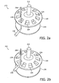
die Anode (110) einen zylindrischen Anodenkörper (111) umfasst,
der erste Brennfleckteil ein erster Vorsprung (120) ist, der zumindest teilweise längs des Umfangs des zylindrischen Körpers (111) angeordnet ist, und
der zweite Brennfleckteil ein zweiter Vorsprung (130) ist, der zumindest teilweise längs des Umfangs des zylindrischen Körpers (111) angeordnet ist. - Röntgenröhre nach Anspruch 3, wobei
der erste Vorsprung (120, 220) mindestens einen ersten Ausschnitt (124, 224) umfasst, und zwar derart, dass- in einer ersten Winkelstellung der Anode (110, 210) der sich vorwiegend parallel zur Z-Achse (113) ausbreitende Elektronenstrahl (106, 206) auf den ersten Vorsprung (120, 220) auftrifft, und- in einer zweiten Winkelstellung der Anode (110, 210) der sich vorwiegend parallel zur Z-Achse (113) ausbreitende Elektronenstrahl (106, 206) auf den zweiten Vorsprung (130, 230) auftrifft. - Röntgenröhre nach Anspruch 1, die weiterhin Folgendes umfasst:eine Steuereinheit (160), die mit der ersten Strahlmanipulationseinheit (125) und der zweiten Strahlmanipulationseinheit (135) gekoppelt ist,- wobei die Steuereinheit (160) dafür eingerichtet ist, die erste Strahlmanipulationseinheit (125) derart zu steuern, dass die erste Strahlmanipulationseinheit (125) nur aktiv ist, wenn der Elektronenstrahl (106) auf den ersten Brennfleckteil (120) auftrifft, und- wobei die Steuereinheit (160) dafür eingerichtet ist, die zweite Strahlmanipulationseinheit (135) derart zu steuern, dass die zweite Strahlmanipulationseinheit (135) nur aktiv ist, wenn der Elektronenstrahl (106) auf den zweiten Brennfleckteil (130) auftrifft.
- Röntgenröhre nach Anspruch 1, die weiterhin Folgendes umfasst:einen dritten, an der Anode (310) ausgebildeten Brennfleckteil (340), der vom ersten Brennfleckteil (320) und vom zweiten Brennfleckteil (330) räumlich getrennt ist, undeine dritte Elektronenstrahlmanipulationseinheit (345), die dafür eingerichtet ist, mit dem Elektronenstrahl (306) zu interagieren, wenn der Elektronenstrahl (306) auf den dritten Brennfleckteil (340) auftrifft.
- Röntgenröhre nach Anspruch 1, die weiterhin Folgendes umfasst:eine weitere Elektronenquelle (405a), die dafür eingerichtet ist, einen weiteren Elektronenstrahl (406a) zu erzeugen,einen weiteren ersten Brennfleckteil (420a) und einen weiteren zweiten Brennfleckteil (430a), die an der Anode (410) ausgebildet sind,eine weitere erste Elektronenstrahlmanipulationseinheit (425a), die dafür eingerichtet ist, mit dem weiteren Elektronenstrahl (406a) zu interagieren, wenn der weitere Elektronenstrahl (406a) auf den weiteren ersten Brennfleckteil (420) auftrifft, undeine weitere zweite Elektronenstrahlmanipulationseinheit (435a), die dafür eingerichtet ist, mit dem weiteren Elektronenstrahl (406a) zu interagieren, wenn der weitere Elektronenstrahl (406a) auf den weiteren zweiten Brennfleckteil (430a) auftrifft,wobei der weitere Elektronenstrahl (406a) und der Elektronenstrahl (406) aus verschiedenen Richtungen auf die Anode (410) auftreffen.
- Röntgenröhre nach Anspruch 7, wobei
der weitere Elektronenstrahl (406a) und der Elektronenstrahl (406) aus entgegengesetzten Richtungen auf die Anode (410) auftreffen. - Röntgensystem, insbesondere ein medizinisches Röntgenbildgebungssystem wie ein Computertomographiesystem (570),
wobei das Röntgensystem mindestens eine Röntgenröhre (100, 300, 400, 575) nach Anspruch 1 umfasst. - Verfahren zum Erzeugen von Röntgenstrahlen, insbesondere zum Erzeugen von zur medizinischen Röntgenbildgebung wie der Computertomographie verwendeten Röntgenstrahlen,
wobei das Verfahren die Verwendung einer Röntgenröhre (100, 300, 400, 575) nach Anspruch 1 umfasst.
Priority Applications (1)
| Application Number | Priority Date | Filing Date | Title |
|---|---|---|---|
| EP07826912A EP2092545B1 (de) | 2006-11-10 | 2007-10-30 | Multifokale röntgenröhre mit mehreren elektronenstrahlmanipulationseinheiten |
Applications Claiming Priority (3)
| Application Number | Priority Date | Filing Date | Title |
|---|---|---|---|
| EP06123817 | 2006-11-10 | ||
| EP07826912A EP2092545B1 (de) | 2006-11-10 | 2007-10-30 | Multifokale röntgenröhre mit mehreren elektronenstrahlmanipulationseinheiten |
| PCT/IB2007/054397 WO2008056299A1 (en) | 2006-11-10 | 2007-10-30 | Multiple focal spot x-ray tube with multiple electron beam manipulating units |
Publications (2)
| Publication Number | Publication Date |
|---|---|
| EP2092545A1 EP2092545A1 (de) | 2009-08-26 |
| EP2092545B1 true EP2092545B1 (de) | 2012-08-29 |
Family
ID=39052711
Family Applications (1)
| Application Number | Title | Priority Date | Filing Date |
|---|---|---|---|
| EP07826912A Not-in-force EP2092545B1 (de) | 2006-11-10 | 2007-10-30 | Multifokale röntgenröhre mit mehreren elektronenstrahlmanipulationseinheiten |
Country Status (4)
| Country | Link |
|---|---|
| US (1) | US7949102B2 (de) |
| EP (1) | EP2092545B1 (de) |
| CN (1) | CN101536134B (de) |
| WO (1) | WO2008056299A1 (de) |
Families Citing this family (23)
| Publication number | Priority date | Publication date | Assignee | Title |
|---|---|---|---|---|
| WO2008053403A2 (en) * | 2006-11-03 | 2008-05-08 | Philips Intellectual Property & Standards Gmbh | Switching scheme for a stereo rotating anode tube |
| WO2009007902A2 (en) * | 2007-07-11 | 2009-01-15 | Philips Intellectual Property & Standards Gmbh | X-ray source for measuring radiation |
| US8687769B2 (en) | 2008-11-25 | 2014-04-01 | Koninklijke Philips N.V. | X-ray anode |
| US8265227B2 (en) | 2009-12-23 | 2012-09-11 | General Electric Company | Apparatus and method for calibrating an X-ray tube |
| CN103430630B (zh) * | 2011-06-28 | 2016-01-20 | 株式会社东芝 | X射线管球以及x射线ct装置 |
| KR20130073727A (ko) * | 2011-12-23 | 2013-07-03 | 삼성전자주식회사 | 복수개의 엑스레이의 초점을 획득하기 위한 방법 및 장치 |
| US9099279B2 (en) * | 2012-04-26 | 2015-08-04 | American Science And Engineering, Inc. | X-ray tube with rotating anode aperture |
| EP2852965A1 (de) * | 2012-05-22 | 2015-04-01 | Koninklijke Philips N.V. | Austastung eines elektronenstrahls bei dynamischem brennfleckspringen in der umfangsrichtung eines rotierenden anodentellers einer röntgenröhre |
| US8923484B2 (en) * | 2012-08-31 | 2014-12-30 | General Electric Company | Motion correction system and method for an x-ray tube |
| US9208986B2 (en) | 2012-11-08 | 2015-12-08 | General Electric Company | Systems and methods for monitoring and controlling an electron beam |
| US9484179B2 (en) | 2012-12-18 | 2016-11-01 | General Electric Company | X-ray tube with adjustable intensity profile |
| US9224572B2 (en) | 2012-12-18 | 2015-12-29 | General Electric Company | X-ray tube with adjustable electron beam |
| GB2517671A (en) | 2013-03-15 | 2015-03-04 | Nikon Metrology Nv | X-ray source, high-voltage generator, electron beam gun, rotary target assembly, rotary target and rotary vacuum seal |
| US20150036792A1 (en) * | 2013-08-01 | 2015-02-05 | Korea Advanced Institute Of Science And Technology | Computed tomography apparatus, and method of generating image by using computed tomography apparatus |
| US9976971B2 (en) * | 2014-03-06 | 2018-05-22 | United Technologies Corporation | Systems and methods for X-ray diffraction |
| TWI629474B (zh) * | 2014-05-23 | 2018-07-11 | 財團法人工業技術研究院 | X光光源以及x光成像的方法 |
| US10460899B2 (en) | 2014-10-06 | 2019-10-29 | Koninklijke Philips N.V. | Modification arrangement for an X-ray generating device |
| WO2016196521A1 (en) | 2015-06-01 | 2016-12-08 | The Regents Of The University Of California | Systems and methods for reducing radiation dose in ct |
| US10262829B2 (en) | 2015-12-14 | 2019-04-16 | General Electric Company | Protection circuit assembly and method for high voltage systems |
| US9502203B1 (en) * | 2015-12-21 | 2016-11-22 | Dymenso LLC | Electron beam gun with kinematic coupling for high power RF vacuum devices |
| US11282668B2 (en) * | 2016-03-31 | 2022-03-22 | Nano-X Imaging Ltd. | X-ray tube and a controller thereof |
| US10748734B2 (en) | 2016-09-05 | 2020-08-18 | Stellarray, Inc. | Multi-cathode EUV and soft x-ray source |
| EP3443904A1 (de) | 2017-08-14 | 2019-02-20 | Koninklijke Philips N.V. | Multifokale röntgenbildgebung |
Citations (1)
| Publication number | Priority date | Publication date | Assignee | Title |
|---|---|---|---|---|
| EP1883093A2 (de) * | 2006-07-28 | 2008-01-30 | Jan Forster | Computertomograph |
Family Cites Families (11)
| Publication number | Priority date | Publication date | Assignee | Title |
|---|---|---|---|---|
| FR2555359A1 (fr) | 1983-11-18 | 1985-05-24 | Thomson Cgr | Dispositif generateur de rayonnement x a tube radiogene longue duree |
| GB9620160D0 (en) | 1996-09-27 | 1996-11-13 | Bede Scient Instr Ltd | X-ray generator |
| DE19832972A1 (de) | 1998-07-22 | 2000-01-27 | Siemens Ag | Röntgenstrahler |
| GB9906886D0 (en) | 1999-03-26 | 1999-05-19 | Bede Scient Instr Ltd | Method and apparatus for prolonging the life of an X-ray target |
| US6895079B2 (en) | 2002-08-20 | 2005-05-17 | General Electric Company | Multiple focal spot X-ray inspection system |
| DE10301071A1 (de) | 2003-01-14 | 2004-07-22 | Siemens Ag | Vorrichtung und Verfahren zum Einstellen der Brennfleckposition einer Röntgenröhre |
| US6968039B2 (en) | 2003-08-04 | 2005-11-22 | Ge Medical Systems Global Technology Co., Llc | Focal spot position adjustment system for an imaging tube |
| JP3909048B2 (ja) | 2003-09-05 | 2007-04-25 | ジーイー・メディカル・システムズ・グローバル・テクノロジー・カンパニー・エルエルシー | X線ct装置およびx線管 |
| US6983035B2 (en) * | 2003-09-24 | 2006-01-03 | Ge Medical Systems Global Technology Company, Llc | Extended multi-spot computed tomography x-ray source |
| US7218700B2 (en) | 2004-05-28 | 2007-05-15 | General Electric Company | System for forming x-rays and method for using same |
| US7317785B1 (en) * | 2006-12-11 | 2008-01-08 | General Electric Company | System and method for X-ray spot control |
-
2007
- 2007-10-30 US US12/513,861 patent/US7949102B2/en not_active Expired - Fee Related
- 2007-10-30 WO PCT/IB2007/054397 patent/WO2008056299A1/en active Application Filing
- 2007-10-30 CN CN200780041380.1A patent/CN101536134B/zh not_active Expired - Fee Related
- 2007-10-30 EP EP07826912A patent/EP2092545B1/de not_active Not-in-force
Patent Citations (1)
| Publication number | Priority date | Publication date | Assignee | Title |
|---|---|---|---|---|
| EP1883093A2 (de) * | 2006-07-28 | 2008-01-30 | Jan Forster | Computertomograph |
Also Published As
| Publication number | Publication date |
|---|---|
| CN101536134B (zh) | 2014-03-12 |
| US20100046712A1 (en) | 2010-02-25 |
| WO2008056299A1 (en) | 2008-05-15 |
| CN101536134A (zh) | 2009-09-16 |
| US7949102B2 (en) | 2011-05-24 |
| EP2092545A1 (de) | 2009-08-26 |
Similar Documents
| Publication | Publication Date | Title |
|---|---|---|
| EP2092545B1 (de) | Multifokale röntgenröhre mit mehreren elektronenstrahlmanipulationseinheiten | |
| US20100074392A1 (en) | X-ray tube with multiple electron sources and common electron deflection unit | |
| US8576988B2 (en) | Distributed X-ray source and X-ray imaging system comprising the same | |
| US6229870B1 (en) | Multiple fan beam computed tomography system | |
| US7945014B2 (en) | X-ray system and method for tomosynthetic scanning | |
| JP5908281B2 (ja) | トモシンセシス及びマンモグラフィ撮像用のx線焦点特性を制御する方法及びシステム | |
| CN103177919B (zh) | 电子光学设备、x射线发射装置及产生电子束的方法 | |
| US7340029B2 (en) | X-ray computed tomography apparatus for fast image acquisition | |
| US7580500B2 (en) | Computer tomography system having a ring-shaped stationary X-ray source enclosing a measuring field | |
| EP2465131B1 (de) | Röntgenröhre mit unabhängiger x- und z-dynamischer brennfleckablenkung | |
| EP2443643B1 (de) | Röntgenröhre zum erzeugen von zwei brennpunkten und medizinische einrichtung damit | |
| US8983024B2 (en) | Tetrahedron beam computed tomography with multiple detectors and/or source arrays | |
| KR20160096024A (ko) | 다중-스펙트럼 x-선 공급원을 사용하는 파노라마 촬상 | |
| JP2005261838A (ja) | X線断層撮影装置 | |
| EP2255374A2 (de) | Kreisförmige tomosynthese-röntgenröhre | |
| US7643606B2 (en) | X-ray computed tomography apparatus with light beam-controlled x-ray source | |
| EP2168137A2 (de) | Röntgenquelle zur strahlungsmessung | |
| WO2013133954A1 (en) | Electromagnetic scanning apparatus for generating a scanning x-ray beam | |
| JP2013093102A (ja) | X線管装置及びx線ct装置 |
Legal Events
| Date | Code | Title | Description |
|---|---|---|---|
| PUAI | Public reference made under article 153(3) epc to a published international application that has entered the european phase |
Free format text: ORIGINAL CODE: 0009012 |
|
| 17P | Request for examination filed |
Effective date: 20090610 |
|
| AK | Designated contracting states |
Kind code of ref document: A1 Designated state(s): AT BE BG CH CY CZ DE DK EE ES FI FR GB GR HU IE IS IT LI LT LU LV MC MT NL PL PT RO SE SI SK TR |
|
| DAX | Request for extension of the european patent (deleted) | ||
| 17Q | First examination report despatched |
Effective date: 20101021 |
|
| GRAP | Despatch of communication of intention to grant a patent |
Free format text: ORIGINAL CODE: EPIDOSNIGR1 |
|
| RIC1 | Information provided on ipc code assigned before grant |
Ipc: H01J 35/14 20060101ALI20120131BHEP Ipc: H01J 35/10 20060101AFI20120131BHEP Ipc: A61B 6/03 20060101ALN20120131BHEP |
|
| RIC1 | Information provided on ipc code assigned before grant |
Ipc: A61B 6/03 20060101ALN20120228BHEP Ipc: H01J 35/14 20060101ALI20120228BHEP Ipc: H01J 35/10 20060101AFI20120228BHEP |
|
| RIN1 | Information on inventor provided before grant (corrected) |
Inventor name: BEHLING, ROLF K. O. |
|
| RAP1 | Party data changed (applicant data changed or rights of an application transferred) |
Owner name: KONINKLIJKE PHILIPS ELECTRONICS N.V. Owner name: PHILIPS INTELLECTUAL PROPERTY & STANDARDS GMBH |
|
| GRAS | Grant fee paid |
Free format text: ORIGINAL CODE: EPIDOSNIGR3 |
|
| GRAA | (expected) grant |
Free format text: ORIGINAL CODE: 0009210 |
|
| AK | Designated contracting states |
Kind code of ref document: B1 Designated state(s): AT BE BG CH CY CZ DE DK EE ES FI FR GB GR HU IE IS IT LI LT LU LV MC MT NL PL PT RO SE SI SK TR |
|
| REG | Reference to a national code |
Ref country code: GB Ref legal event code: FG4D |
|
| REG | Reference to a national code |
Ref country code: CH Ref legal event code: EP |
|
| REG | Reference to a national code |
Ref country code: AT Ref legal event code: REF Ref document number: 573452 Country of ref document: AT Kind code of ref document: T Effective date: 20120915 |
|
| REG | Reference to a national code |
Ref country code: IE Ref legal event code: FG4D |
|
| REG | Reference to a national code |
Ref country code: DE Ref legal event code: R084 Ref document number: 602007025167 Country of ref document: DE |
|
| REG | Reference to a national code |
Ref country code: DE Ref legal event code: R096 Ref document number: 602007025167 Country of ref document: DE Effective date: 20121025 |
|
| REG | Reference to a national code |
Ref country code: GB Ref legal event code: 746 Effective date: 20121005 |
|
| REG | Reference to a national code |
Ref country code: DE Ref legal event code: R084 Ref document number: 602007025167 Country of ref document: DE Effective date: 20121006 |
|
| REG | Reference to a national code |
Ref country code: AT Ref legal event code: MK05 Ref document number: 573452 Country of ref document: AT Kind code of ref document: T Effective date: 20120829 |
|
| REG | Reference to a national code |
Ref country code: NL Ref legal event code: VDEP Effective date: 20120829 |
|
| REG | Reference to a national code |
Ref country code: LT Ref legal event code: MG4D Effective date: 20120829 |
|
| PG25 | Lapsed in a contracting state [announced via postgrant information from national office to epo] |
Ref country code: AT Free format text: LAPSE BECAUSE OF FAILURE TO SUBMIT A TRANSLATION OF THE DESCRIPTION OR TO PAY THE FEE WITHIN THE PRESCRIBED TIME-LIMIT Effective date: 20120829 Ref country code: CY Free format text: LAPSE BECAUSE OF FAILURE TO SUBMIT A TRANSLATION OF THE DESCRIPTION OR TO PAY THE FEE WITHIN THE PRESCRIBED TIME-LIMIT Effective date: 20120829 Ref country code: IS Free format text: LAPSE BECAUSE OF FAILURE TO SUBMIT A TRANSLATION OF THE DESCRIPTION OR TO PAY THE FEE WITHIN THE PRESCRIBED TIME-LIMIT Effective date: 20121229 Ref country code: FI Free format text: LAPSE BECAUSE OF FAILURE TO SUBMIT A TRANSLATION OF THE DESCRIPTION OR TO PAY THE FEE WITHIN THE PRESCRIBED TIME-LIMIT Effective date: 20120829 Ref country code: LT Free format text: LAPSE BECAUSE OF FAILURE TO SUBMIT A TRANSLATION OF THE DESCRIPTION OR TO PAY THE FEE WITHIN THE PRESCRIBED TIME-LIMIT Effective date: 20120829 |
|
| PG25 | Lapsed in a contracting state [announced via postgrant information from national office to epo] |
Ref country code: SE Free format text: LAPSE BECAUSE OF FAILURE TO SUBMIT A TRANSLATION OF THE DESCRIPTION OR TO PAY THE FEE WITHIN THE PRESCRIBED TIME-LIMIT Effective date: 20120829 Ref country code: SI Free format text: LAPSE BECAUSE OF FAILURE TO SUBMIT A TRANSLATION OF THE DESCRIPTION OR TO PAY THE FEE WITHIN THE PRESCRIBED TIME-LIMIT Effective date: 20120829 Ref country code: BE Free format text: LAPSE BECAUSE OF FAILURE TO SUBMIT A TRANSLATION OF THE DESCRIPTION OR TO PAY THE FEE WITHIN THE PRESCRIBED TIME-LIMIT Effective date: 20120829 Ref country code: PT Free format text: LAPSE BECAUSE OF FAILURE TO SUBMIT A TRANSLATION OF THE DESCRIPTION OR TO PAY THE FEE WITHIN THE PRESCRIBED TIME-LIMIT Effective date: 20121231 Ref country code: LV Free format text: LAPSE BECAUSE OF FAILURE TO SUBMIT A TRANSLATION OF THE DESCRIPTION OR TO PAY THE FEE WITHIN THE PRESCRIBED TIME-LIMIT Effective date: 20120829 Ref country code: GR Free format text: LAPSE BECAUSE OF FAILURE TO SUBMIT A TRANSLATION OF THE DESCRIPTION OR TO PAY THE FEE WITHIN THE PRESCRIBED TIME-LIMIT Effective date: 20121130 |
|
| PG25 | Lapsed in a contracting state [announced via postgrant information from national office to epo] |
Ref country code: RO Free format text: LAPSE BECAUSE OF FAILURE TO SUBMIT A TRANSLATION OF THE DESCRIPTION OR TO PAY THE FEE WITHIN THE PRESCRIBED TIME-LIMIT Effective date: 20120829 Ref country code: NL Free format text: LAPSE BECAUSE OF FAILURE TO SUBMIT A TRANSLATION OF THE DESCRIPTION OR TO PAY THE FEE WITHIN THE PRESCRIBED TIME-LIMIT Effective date: 20120829 Ref country code: CZ Free format text: LAPSE BECAUSE OF FAILURE TO SUBMIT A TRANSLATION OF THE DESCRIPTION OR TO PAY THE FEE WITHIN THE PRESCRIBED TIME-LIMIT Effective date: 20120829 Ref country code: EE Free format text: LAPSE BECAUSE OF FAILURE TO SUBMIT A TRANSLATION OF THE DESCRIPTION OR TO PAY THE FEE WITHIN THE PRESCRIBED TIME-LIMIT Effective date: 20120829 Ref country code: DK Free format text: LAPSE BECAUSE OF FAILURE TO SUBMIT A TRANSLATION OF THE DESCRIPTION OR TO PAY THE FEE WITHIN THE PRESCRIBED TIME-LIMIT Effective date: 20120829 Ref country code: ES Free format text: LAPSE BECAUSE OF FAILURE TO SUBMIT A TRANSLATION OF THE DESCRIPTION OR TO PAY THE FEE WITHIN THE PRESCRIBED TIME-LIMIT Effective date: 20121210 |
|
| PG25 | Lapsed in a contracting state [announced via postgrant information from national office to epo] |
Ref country code: PL Free format text: LAPSE BECAUSE OF FAILURE TO SUBMIT A TRANSLATION OF THE DESCRIPTION OR TO PAY THE FEE WITHIN THE PRESCRIBED TIME-LIMIT Effective date: 20120829 Ref country code: IT Free format text: LAPSE BECAUSE OF FAILURE TO SUBMIT A TRANSLATION OF THE DESCRIPTION OR TO PAY THE FEE WITHIN THE PRESCRIBED TIME-LIMIT Effective date: 20120829 Ref country code: MC Free format text: LAPSE BECAUSE OF NON-PAYMENT OF DUE FEES Effective date: 20121031 Ref country code: SK Free format text: LAPSE BECAUSE OF FAILURE TO SUBMIT A TRANSLATION OF THE DESCRIPTION OR TO PAY THE FEE WITHIN THE PRESCRIBED TIME-LIMIT Effective date: 20120829 |
|
| REG | Reference to a national code |
Ref country code: CH Ref legal event code: PL |
|
| PLBE | No opposition filed within time limit |
Free format text: ORIGINAL CODE: 0009261 |
|
| STAA | Information on the status of an ep patent application or granted ep patent |
Free format text: STATUS: NO OPPOSITION FILED WITHIN TIME LIMIT |
|
| REG | Reference to a national code |
Ref country code: FR Ref legal event code: ST Effective date: 20130628 |
|
| PG25 | Lapsed in a contracting state [announced via postgrant information from national office to epo] |
Ref country code: CH Free format text: LAPSE BECAUSE OF NON-PAYMENT OF DUE FEES Effective date: 20121031 Ref country code: BG Free format text: LAPSE BECAUSE OF FAILURE TO SUBMIT A TRANSLATION OF THE DESCRIPTION OR TO PAY THE FEE WITHIN THE PRESCRIBED TIME-LIMIT Effective date: 20121129 Ref country code: LI Free format text: LAPSE BECAUSE OF NON-PAYMENT OF DUE FEES Effective date: 20121031 |
|
| REG | Reference to a national code |
Ref country code: IE Ref legal event code: MM4A |
|
| 26N | No opposition filed |
Effective date: 20130530 |
|
| PG25 | Lapsed in a contracting state [announced via postgrant information from national office to epo] |
Ref country code: FR Free format text: LAPSE BECAUSE OF NON-PAYMENT OF DUE FEES Effective date: 20121031 |
|
| REG | Reference to a national code |
Ref country code: DE Ref legal event code: R097 Ref document number: 602007025167 Country of ref document: DE Effective date: 20130530 |
|
| PG25 | Lapsed in a contracting state [announced via postgrant information from national office to epo] |
Ref country code: IE Free format text: LAPSE BECAUSE OF NON-PAYMENT OF DUE FEES Effective date: 20121030 |
|
| PG25 | Lapsed in a contracting state [announced via postgrant information from national office to epo] |
Ref country code: MT Free format text: LAPSE BECAUSE OF FAILURE TO SUBMIT A TRANSLATION OF THE DESCRIPTION OR TO PAY THE FEE WITHIN THE PRESCRIBED TIME-LIMIT Effective date: 20120829 |
|
| PG25 | Lapsed in a contracting state [announced via postgrant information from national office to epo] |
Ref country code: TR Free format text: LAPSE BECAUSE OF FAILURE TO SUBMIT A TRANSLATION OF THE DESCRIPTION OR TO PAY THE FEE WITHIN THE PRESCRIBED TIME-LIMIT Effective date: 20120829 |
|
| REG | Reference to a national code |
Ref country code: DE Ref legal event code: R081 Ref document number: 602007025167 Country of ref document: DE Owner name: PHILIPS GMBH, DE Free format text: FORMER OWNER: PHILIPS INTELLECTUAL PROPERTY & STANDARDS GMBH, 20099 HAMBURG, DE Effective date: 20140327 Ref country code: DE Ref legal event code: R081 Ref document number: 602007025167 Country of ref document: DE Owner name: PHILIPS DEUTSCHLAND GMBH, DE Free format text: FORMER OWNER: PHILIPS INTELLECTUAL PROPERTY & STANDARDS GMBH, 20099 HAMBURG, DE Effective date: 20140327 |
|
| PG25 | Lapsed in a contracting state [announced via postgrant information from national office to epo] |
Ref country code: LU Free format text: LAPSE BECAUSE OF NON-PAYMENT OF DUE FEES Effective date: 20121030 |
|
| PG25 | Lapsed in a contracting state [announced via postgrant information from national office to epo] |
Ref country code: HU Free format text: LAPSE BECAUSE OF FAILURE TO SUBMIT A TRANSLATION OF THE DESCRIPTION OR TO PAY THE FEE WITHIN THE PRESCRIBED TIME-LIMIT Effective date: 20071030 |
|
| REG | Reference to a national code |
Ref country code: DE Ref legal event code: R082 Ref document number: 602007025167 Country of ref document: DE Representative=s name: MEISSNER, BOLTE & PARTNER GBR, DE Ref country code: DE Ref legal event code: R081 Ref document number: 602007025167 Country of ref document: DE Owner name: PHILIPS GMBH, DE Free format text: FORMER OWNER: PHILIPS DEUTSCHLAND GMBH, 20099 HAMBURG, DE Ref country code: DE Ref legal event code: R082 Ref document number: 602007025167 Country of ref document: DE Representative=s name: MEISSNER BOLTE PATENTANWAELTE RECHTSANWAELTE P, DE |
|
| PGFP | Annual fee paid to national office [announced via postgrant information from national office to epo] |
Ref country code: GB Payment date: 20161028 Year of fee payment: 10 |
|
| GBPC | Gb: european patent ceased through non-payment of renewal fee |
Effective date: 20171030 |
|
| PG25 | Lapsed in a contracting state [announced via postgrant information from national office to epo] |
Ref country code: GB Free format text: LAPSE BECAUSE OF NON-PAYMENT OF DUE FEES Effective date: 20171030 |
|
| PGFP | Annual fee paid to national office [announced via postgrant information from national office to epo] |
Ref country code: DE Payment date: 20181228 Year of fee payment: 12 |
|
| REG | Reference to a national code |
Ref country code: DE Ref legal event code: R119 Ref document number: 602007025167 Country of ref document: DE |
|
| PG25 | Lapsed in a contracting state [announced via postgrant information from national office to epo] |
Ref country code: DE Free format text: LAPSE BECAUSE OF NON-PAYMENT OF DUE FEES Effective date: 20200501 |