EP2091812B1 - Aile d'aeronef - Google Patents
Aile d'aeronef Download PDFInfo
- Publication number
- EP2091812B1 EP2091812B1 EP07856579A EP07856579A EP2091812B1 EP 2091812 B1 EP2091812 B1 EP 2091812B1 EP 07856579 A EP07856579 A EP 07856579A EP 07856579 A EP07856579 A EP 07856579A EP 2091812 B1 EP2091812 B1 EP 2091812B1
- Authority
- EP
- European Patent Office
- Prior art keywords
- slot
- mainplane
- additional airfoil
- wing
- area
- Prior art date
- Legal status (The legal status is an assumption and is not a legal conclusion. Google has not performed a legal analysis and makes no representation as to the accuracy of the status listed.)
- Not-in-force
Links
Images


Classifications
-
- B—PERFORMING OPERATIONS; TRANSPORTING
- B64—AIRCRAFT; AVIATION; COSMONAUTICS
- B64C—AEROPLANES; HELICOPTERS
- B64C9/00—Adjustable control surfaces or members, e.g. rudders
- B64C9/02—Mounting or supporting thereof
-
- B—PERFORMING OPERATIONS; TRANSPORTING
- B64—AIRCRAFT; AVIATION; COSMONAUTICS
- B64C—AEROPLANES; HELICOPTERS
- B64C7/00—Structures or fairings not otherwise provided for
-
- B—PERFORMING OPERATIONS; TRANSPORTING
- B64—AIRCRAFT; AVIATION; COSMONAUTICS
- B64C—AEROPLANES; HELICOPTERS
- B64C9/00—Adjustable control surfaces or members, e.g. rudders
- B64C9/14—Adjustable control surfaces or members, e.g. rudders forming slots
- B64C2009/143—Adjustable control surfaces or members, e.g. rudders forming slots comprising independently adjustable elements for closing or opening the slot between the main wing and leading or trailing edge flaps
Definitions
- the invention relates to a wing for an aircraft as claimed in the precharacterizing clause of claim 1 and as claimed in the precharacterizing clause of claim 8.
- DE 14 81 578 A1 discloses a wing for an aircraft, having a mainplane which has an upper face, a lower face and an aerodynamically shaped nose area, and having an additional airfoil, which is articulated on the mainplane, and has an aerodynamically shaped nose area, which is located at the front in the flow direction and an aerodynamically shaped rear-face area, which faces the nose area of the mainplane.
- the additional airfoil can be extended from a retracted state opening a slot (which guides air from the lower face of the slat to the upper face of the mainplane) between the nose area of the mainplane and the rear-face area of the additional airfoil, in order to increase the lift.
- a variable-position sealing element is arranged on the lower face of the additional airfoil and, when the additional airfoil is retracted, forms a part of its aerodynamic profile and, when the additional airfoil is in the retracted state, covers the slot between the mainplane and the additional airfoil on the lower face.
- the sealing element is provided in the form of a rigid flap which forms a major part of the aerodynamically shaped nose area and a part of the rear-face area of the additional airfoil and can be pivoted somewhat about the center point of an imaginary profile nose circle towards the mainplane and, when the slat is retracted, covers the remaining slot which is located between the slat and the mainplane and represents an interruption in the profile contour.
- a wing such as this is presupposed to be known in the precharacterizing clause of claim 1.
- DE 10 2004 058 537 A1 discloses a wing for an aircraft having a mainplane and an additional airfoil which is articulated on the mainplane.
- separating surfaces are provided which can be moved into the slot area between the additional airfoil and the mainplane when the additional airfoil is extended.
- the separating surface is formed by a variable-position flap at the lower end of the nose area of the additional airfoil, which is folded on to the rear-face area when the slat is retracted and, when the slat is extended, is folded into the slot between the slat and the mainplane, lengthening the aerodynamic profile of the lower face of the additional airfoil.
- GB 2 096 551 discloses a method to optimize the cruising conditions of an aircraft including detecting of current flight data and varying the curvature of the wing in a defined manner as a function fof these flight data.
- a wing such as this is presupposed to be known in the precharacterizing part of claim 8.
- an aircraft wing having a main portion to the rear of which is carried a lift increasing portion including a rotary actuator.
- the lift increasing portion is movable between a first position in which the leading region for the lift increasing portion lies close to the trailing region of the main portion and a second portion in which a slot is formed between the trailing region and the leading region for lift inversing purposes.
- DE 199 25 560 A1 discloses a mainplane with an additional airfoil movable at the leading edge of the mainplane and having slot-varying device for influencing the airflow between the mainplane and the additional airfoil.
- the object of the invention is to provide an improved wing for an aircraft having a mainpiane, an additional airfoil and a variable-position sealing element in order in particular to significantly reduce the noise that occurs during the landing approach.
- the object is achieved by a wing having the features of claim 1.
- the object is also achieved by a wing having the features of claim 8.
- the invention provides a wing for an aircraft, having a mainplane, which has an upper face, a lower face and an aerodynamically shaped nose area, and an additional airfoil, which is articulated on the mainplane and has an aerodynamically shaped nose area facing the flow and an aerodynamically shaped rear-face area facing the nose area of the mainplane, and can be extended from a retracted state with a slot area between the nose area of the mainplane and the rear-face area of the additional airfoil being opened, and having a variable-position sealing element, which is arranged on the lower face of the additional airfoil, forms a part of its aerodynamic profile when the additional airfoil is extended, and at least partially covers the slot area between the mainplane and the additional airfoil on the lower face when the additional airfoil is in the retracted state.
- the invention provides that the sealing element is arranged, formed separately from the nose area of the additional airfoil, at the transition between the nose area and the rear-face area of the additional airfoil and can be varied between a curved configuration, in which it forms a part of the aerodynamic profile of the additional airfoil with a curved transition from the nose area to the rear-face area of the additional airfoil when the additional airfoil is extended, and an extended configuration, in which when the additional airfoil is in the retracted state, it at least partially covers the slot area between the mainplane and the additional airfoil on the lower face.
- One advantage of the embodiment of the wing according to the invention is that not only does it have an optimum profile in the sense of maximizing the increase in lift in the extended state of the additional airfoil but also has an optimum profile shape in the sense of good flying characteristics and performance when the additional airfoil is in the retracted state.
- a further advantage of the wing according to the invention is that the noise which otherwise occurs, in particular during a landing approach, when the additional airfoil is extended owing to the rear face of additional airfoils (also referred to as "slat hooks"), that have been used until now, having a cambered taper, is considered reduced by the curved sealing element.
- the curved sealing element results in the rear face of the additional airfoil having a continuous shape, without any sudden changes in the extended state, thus significantly reducing vortex formation in the slot area, and therefore the noise that is generated.
- the sealing element is designed to be elastically flexible at least in places in the profile chord direction of the wing, such that its shape can be adapted. This advantageously ensures reliable extension and retraction of the additional airfoil even in the event of a malfunction of the sealing element.
- the sealing element has flexibly variable curvature so that, when the additional airfoil is extended, it forms a part of its aerodynamic profile in a curved configuration and, when the additional airfoil is in the retracted state, in an extended configuration it at least partially covers the slot area between the mainplane and the additional airfoil on the lower face.
- the front end of the sealing element in the profile chord direction is fixed to the additional airfoil.
- the front end of the sealing element in the profile chord direction is mounted with respect to the additional airfoil, such that it can rotate about the span direction or transversely with respect to the flow direction, and has a curved part which forms the curved transition from the nose area of the rear-face area of the additional airfoil when the additional airfoil is extended, and, at its rear end in the profile chord direction has an extended part which covers the slot area between the mainplane and the additional airfoil on the lower face when the additional airfoil is in the retracted state.
- the sealing element can be varied between the curved configuration, in which it forms a part of the aerodynamic profile of the additional airfoil with the curved transition from the nose area to the rear-face area of the additional airfoil, when the additional airfoil is extended and the extended configuration, in which it at least partially covers the slot area between the mainplane and the additional airfoil on the lower face when the additional airfoil is in the retracted state by aerodynamic forces acting between the mainplane and the additional airfoil.
- the sealing element can be varied by a drive device, which is coupled to the sealing element between the curved configuration, in which it forms a part of the aerodynamic profile of the additional airfoil with the curved transition from the nose area to the rear-face area of the additional airfoil when the additional airfoil is extended, and the extended configuration in which it at least partially covers the slot area between the mainplane and the additional airfoil on the lower face when the additional airfoil is in the retracted state.
- the drive device may be arranged in the sealing element.
- the drive device may be arranged in the curved part of the sealing element which forms the curved transition from the nose area to the rear-face area of the additional airfoil.
- the drive device is kinematically coupled to the movement of the additional airfoil with respect to the mainplane in the sense of positive movement of the sealing element during extension and retraction of the additional airfoil.
- the invention provides in particular for the drive device to be kinematically coupled to a rail by means of which the additional airfoil is articulated on the mainplane.
- a wing for an aircraft, comprising a mainplane, which has an upper face, a lower face and an aerodynamically shaped rear-face area, an additional airfoil, which is arranged on the rear face of the mainplane and is articulated on the mainplane, an aerodynamically shaped nose area facing the rear-face area of the mainplane, and which can be moved between a retracted and extended state opening a slot area between the rear-face area of the mainplane and the nose area of the additional airfoil.
- a variable-position sealing element which is arranged on the rear face of the mainplane and, when the additional airfoil is extended, it forms a part of the aerodynamic profile of the mainplane and, when the additional airfoil is in the retracted state, at least partially covers the slot area between the mainplane and the additional airfoil on the lower face, with the sealing element being arranged at the transition between the lower face and the rear-face area of the mainplane and can be varied between a curved configuration, in which it forms a part of the aerodynamic profile of the mainplane at the curved transition from the lower face to the rear-face area of the mainplane when the additional airfoil is extended, and an extended configuration in which it at least partially covers the slot area between the mainplane and the additional airfoil on the lower face when the additional airfoil is in the retracted state.
- One advantage of the design of the wing according to the invention as used in this embodiment is that, in addition, it not only has an optimum profile in the sense of maximizing the increase in lift when the additional airfoil is in the retracted state, but also has an optimum profile shape in the sense of good flying characteristics and performance when the additional airfoil is in the retracted state.
- a further advantage of this wing according to the invention is also that the noise which otherwise occurs when the additional airfoil is extended, in particular during the landing approach, is considerably reduced by the curved sealing element.
- the curved sealing element provides the rear face of the mainplane with a continuous shape, without any sudden changes, in the extended state, considerably reducing vortex formation in the slot area, and therefore the noise that is generated.
- the additional airfoil is retracted, that is to say in particular during cruise flight, the bridging of the slot between the mainplane and the additional airfoil results in a smoother profile lower face contour, thus ensuring optimum aerodynamic quality.
- the sealing element is designed to be elastically flexible at least in places in the profile chord direction of the wing, and for its shape therefore to be adaptable. This advantageously ensures reliable extension and retraction of the additional airfoil, even in the event of a malfunction of the sealing element.
- the sealing element has flexibly variable curvature so that, when the additional airfoil is extended in a curved configuration it forms part of its aerodynamic profile and, when the additional airfoil is in the retracted state, in an extended configuration, it at least partially covers the slot area between the mainplane and the additional airfoil on the lower face.
- calculations show that a continuous rear face of the mainplane, without any sudden changes, formed by the curved sealing element, reduces vortex formation allowing a considerable reduction in noise to be achieved.
- the front end of the sealing element in the profile chord direction is fixed to the mainplane.
- the front end of the sealing element in its profile chord direction is mounted with respect to the mainplane such that it can rotate about the span direction and a curved part, which forms the curved transition from the lower face to the rear-face area of the mainplane when the additional airfoil is extended and, at its rear end in the profile chord direction, has an extended part which covers the slot area between the mainplane and the additional airfoil on the lower face when the additional airfoil is in the retracted state.
- the sealing element can be varied between the curved configuration and the extended configuration by aerodynamic forces acting between the mainplane and the additional airfoil.
- the sealing element can be varied between the curved configuration and the extended configuration by means of a drive device which is coupled to the sealing element.
- the drive device is arranged in the sealing element.
- the drive device is arranged in the curved part of the sealing element which forms the curved transition from the lower face to the rear-face area of the mainplane.
- the drive device is kinematically coupled to the movement of the additional airfoil with respect to the mainplane in the sense of positive movement of the sealing element during extension and retraction of the additional airfoil.
- the drive device can be kinematically coupled to a rail, by means of which the additional airfoil is articulated on the mainplane.
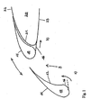
- Figures 1 to 8 show various exemplary embodiments of a wing of an aircraft with a mainplane 20, which has an upper face and an upper profile surface area 22 (suction side) and a lower face or a lower profile surface area 23 (pressure side) and an aerodynamically shaped nose area 21.
- a slat or additional airfoil 10 is articulated on the mainplane 20 and has an aerodynamically shaped nose area 11, located at the front in the flow direction and an aerodynamically shaped rear face area 12, facing the nose area 21 of the mainplane 20.
- the additional airfoil 10 can be extended from a retracted position, opening a slot or slot area 9, which guides air from the lower face of the slat to the upper face of the mainplane in order to increase lift, between the nose area 21 of the mainplane 20 and the rear face area 12 of the additional airfoil 10 and/or can be moved between a retracted state and one or more extended states.
- a sealing element 16; 26; 36; 46 which can move or whose position and/or shape are/is variable, or a deformable slot-varying or sealing apparatus or a sealing apparatus which can itself be deformed between two extreme position states is arranged on the lower face of the additional airfoil 10.
- the sealing apparatus When the additional airfoil 10 is extended, the sealing apparatus forms a part of its aerodynamic profile, that is to say of its aerodynamic profile surface, or rests at least in places on the profile surface of the additional airfoil and, when the additional airfoil 10 is in the retracted state, partially or entirely covers the slot 9, which remains when the additional airfoil 10 is retracted, between the mainplane 20 and the additional airfoil 10 on the lower face 23 of the mainplane 20 or the lower face 23a of the additional airfoil 10.
- the sealing element or the slot-varying apparatus 16; 26; 36; 46 is arranged at the transition in the assumed direction of incident flow S between the surface area facing the flow or the nose area 11, and the surface area facing away from the flow, or the rear-face area 12, of the additional airfoil 10.
- the sealing element 16; 26; 36; 46 can be varied and moved between a configuration in which it rests at least in places on the additional airfoil 10, that is to say a retracted or curved configuration in which, when the additional airfoil 10 is extended it forms a part of its aerodynamic profile with a curved transition from the nose area 11 to the rear face area 12 of the additional airfoil 10, and an extended configuration or slot-influencing configuration, in which it covers the slot area 9 between the mainplane 20 and the additional airfoil 10 on the lower face when the additional airfoil is in the retracted state.
- the sealing apparatus 16; 26; 36; 46 can entirely or only partially close the slot 9 between the mainplane 20 and the additional airfoil 10 on the lower face of the mainplane 20 when the additional airfoil 10 is retracted to a greater or lesser extent.
- the slot-influencing state may, in particular be a slot-closing state in which the slot-varying apparatus closes the slot 9.
- the slot-varying apparatus 16; 26; 36; 46 is fixed at its end 16a facing the lower faces 23, 23a, seen in the longitudinal direction L, on the additional airfoil 10, such that a second end 16b located at the opposite end to the first end 16a, moves relative to the additional airfoil 10 during variation of the movement state of the slot-varying apparatus 16; 26; 36; 46.
- the sealing apparatus or slot-varying apparatus 16; 26; 36; 46 covers the slot 9 entirely ( Figure 1 a) or only partially (not illustrated).
- the second end 16b which is at the opposite end to the first end 16a of the slot-varying apparatus rests at a point on the mainplane surface on the transitional area between the upper face 22 and the lower face 23, at which the longitudinal direction L at the second end 16b and the profile of the mainplane contour, resting on it at the contact point A, or the tangent to this at the contact point A, form an acute angle with respect to one another.
- the slot-varying apparatus 16; 26; 36; 46 assumes a movement or deformation state in which the longitudinal axis of its cross section, which lies on the plane covered by the wing thickness direction and the incident-flow direction or the wing depth direction, departs at this point from the surface contour of the additional airfoil 10, starting from the first end 16a, and faces the mainplane 20.
- the longitudinal axis of the slot-varying apparatus may, in particular, have a curved profile.
- the slot-varying apparatus 16; 26; 36; 46 can follow the contour profile of the additional airfoil 10 between the nose area and rear-face area thereof, on the lower face 23a of the additional airfoil, at least in places, and preferably in its profile of the longitudinal direction L. It is also possible for the slot-varying apparatus 16; 26; 36; 46 to project by a predetermined amount from the contour of the additional airfoil on the rear-face area in its retracted state, provided that this does not result in significant aerodynamic disadvantages. It is also possible to for the slot-varying apparatus 16; 26; 36; 46 to rest entirely or partially on the additional airfoil in its retracted state. In its extended state, the second end 16b of the slot-varying apparatus may rest on the contour of the lower face 23 or on the contour of the transitional area between the lower face 23 or the upper face 22 of the mainplane 20.
- the slot-varying apparatus 16; 26; 36; 46 may be designed to be elastically flexible at least in places seen in its longitudinal direction or in the profile chord direction (see Figure 7a ), in order not to impede retraction of the additional airfoil 10 in the event of a failure or emergency, and to prevent damage to the nose area 21 of the mainplane 20 during retraction of the additional airfoil 10.
- the sealing element is formed from a soft material, for example, from glass-fiber-reinforced silicone.
- a slot-varying apparatus 16; 26; 36; 46 such as this ensures adequate flexibility in order to ensure the desired matching of the shape of the sealing element to the profile or to the profile contour of the additional airfoil 10.
- the slot-varying apparatus 16; 26; 36; 46 or the sealing element 16 may be flexible or may have a variable or movable camber such that, when the additional airfoil 10 was extended, in a touching or retracted state which is shown in Figures 1a , 2a and 3a , a part of the aerodynamic profile of the additional airfoil 10, the sealing element 16 from the aerodynamic point of view forms a part of the aerodynamic profile of the additional airfoil 10 with a curved transition, without any discontinuity, from the nose area 11 to the rear-face area 12 of the additional airfoil 10.
- This state may be provided in particular such that the tangent to the trailing edge 16b runs above the stagnation point of the mainplane 20 when the additional airfoil 10 is in this position. If the transition not only has no sudden changes, that is to say it has a continuous gradient, but furthermore also has continuous curvature, this is particularly useful in order to prevent separation of the boundary layer.
- the slot-varying apparatus 16; 26; 36; 46 is designed such that, when the additional airfoil 10 is in the retracted state, this slot-varying apparatus 16; 26; 36; 46 entirely or at least partially covers the slot 9, which remains when the additional airfoil 10 is retracted, between the mainplane 20 and the additional airfoil 10 on the lower face or pressure side of the wing in its extended state, as is shown in Figures 1b , 2b and 3b , and thus influences the flow in the slot or prevents flow through the slot from the lower face 23, 23a.
- the front end of the slot-varying apparatus 16 in its profile chord direction is attached or fixed to or articulated on the additional airfoil 10.
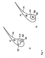
- the slot-varying apparatus 26; 36; 46 has an actuating part 28 which is mounted such that it can rotate about a rotation axis 28a, and a slat part 29; 39; 49 which is fitted to its rear end 28b seen in the flow direction S or in the profile chord direction P such that, during rotation of the actuating part, the slat part is folded in or out as appropriate.
- the rotation axis 28a need not be located within the rotating part but may be located outside it depending on the kinematic application.
- a section of the external contour of the rotating part may in this case form a part of the surface contour of the additional airfoil 10.
- the slat part is in the form of a rigid slat part.
- the slat part may also be in the form of a flexible slat part, or a variable-shape slat part.
- the slot-varying apparatus 26; 36; 46 rests on the contour of the additional airfoil 10 in its retracted state ( Figures 5d , 6b , 8e) and, in its extended state, extends away from the contour of the additional airfoil 10 such that the slot-varying apparatus 26; 36; 46 can at least partially cover the slot 9 beyond a predetermined position of the additional airfoil 10 at which it approaches the additional airfoil 10.
- the slot-varying apparatus 26; 36; 46 when the additional airfoil 10 is in the retracted state ( Figures 5d , 6b and 8e) covers the slot area 9 between the mainplane 20 and the additional airfoil 10 on the lower face at least partially with its slat part 29; 39; 49 and, when the additional airfoil 10 is extended ( Figures 4a, 4b , 5a, 5b , 5c , 6b , 7b and 8a ) the slat part 29 of the slot-varying apparatus 26; 36; 46 rests on the curved transition, which is located on the lower face of the additional slat 10, from the nose area 11 to the rear-face area 12.
- the slot-varying apparatus 26; 36; 46 is therefore mounted such that it can rotate about the span direction with respect to the additional airfoil 10, that is to say at its front end in the profile chord direction or its side facing the flow S.
- the curved part 28; 38; 48 which forms the curved transition from the nose area 11 to the rear-face area 12 of the additional airfoil 10, may, for example have a tubular section of a tube which extends in the span direction, as shown in Figures 4 , 5 , 7 and 8 , or may have the cross section of a tubular segment of a tubular segment which extends in the span direction, as shown in Figure 6 .
- the slot-varying apparatus 16; 26; 36; 46 may be designed and coupled to the additional slat 10 such that it can be moved by aerodynamic forces acting between the mainplane 20 and the additional airfoil 10.
- the movement states are in this case located between the retracted state, in which the slot-varying apparatus forms a part of the aerodynamic profile of the additional airfoil 10 with the curved transition from the nose area 11 to the rear-face area 12 to the additional airfoil 30 when the additional airfoil 10 is extended, and the extended state, in which the slot-varying apparatus at least partially covers the remaining slot area 9 between the mainplane 20 and the additional airfoil 10 on the lower face when the additional airfoil 10 is in the retracted state ( Figures 3a and 3b ).
- the slot-varying apparatus 16; 26; 36; 46 is coupled to a drive device 5; 17; 27; 37; 47 which can move the slot-varying apparatus between the retracted state and the extended state, with this slot-varying apparatus forming a part of the aerodynamic profile of the additional airfoil 10 with the curved transition from the nose area 11 to the rear-face area 12 of the addition al airfoil 10 when the additional airfoil 10 is extended, or covering the profile or resting on it, and in its extended state, it can cover the slot area 9 between the mainplane 20 and the additional airfoil 10 on the lower face when the additional airfoil 10 is in the retracted state.
- the drive apparatus operates the slot-bearing apparatus and therefore controls the movement state of the slot-varying apparatus.
- the position of the drive apparatus may be provided in various ways.
- the drive device 17; 27; 47 is located outside the slot-varying apparatus.
- the drive device 37 may be located within the slot-varying apparatus.
- the drive apparatus may, in particular be arranged within the rotating part and thus in the area of the curved transition from the nose area 11 to the rear-face area 12 of the additional airfoil 10.
- the operating state of the drive device 47 and therefore the movement state of the slot-varying apparatus 46 are coupled to the state of the additional airfoil, that is to say to the position of the additional airfoil 10, while it is being extended and retracted.
- the coupling may be provided, for example, via a sensor 60 which is functionally connected to the drive apparatus, that is to say in particular electrically or mechanically connected and transmits appropriate signals to the drive apparatus for one or more movement states of the additional airfoil 10 relative to the mainplane 20.
- the sensor 60 may be a probe 60 which is arranged between the mainplane 20 and the additional airfoil 10 such that, while the slot 9 is closing, it is touched by the nose area 21 of the mainplane 20 and, as a result of this sends an appropriate signal to the drive apparatus in order to operate it.
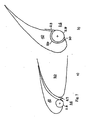
- Figure 8a shows the wing with the additional airfoil 10 completely extended
- Figure 8b shows it with the additional airfoil 10 partially extended
- Figure 8c shows it with the additional airfoil 10 completely retracted.
- the curvature of the rotating part 28; 38; 48 is provided such that it is advantageous with respect to the aerodynamic characteristics of the slat 10 and the integration of the drive 27; 37; 47 as illustrated by way of example in Figures 5a, 5b and 5c .
- the invention therefore provides for the slot-varying apparatus 16; 26; 36; 46 to be deformable, at least in places, transversely with respect to its longitudinal direction L or the profile chord direction of the wing, and in the process, for example to be designed to be elastically flexible. This ensures reliable extension and retraction of the additional airfoil even in the event of a malfunction of the sealing element. This is shown by way of example in Figure 7a for the exemplary embodiment from Figures 4 and 5 .
- the slot-varying apparatus may be accommodated at least partially in a depression or recess in the additional airfoil 10, as illustrated as the example in Figure 7b .
- the cutout or depression extends in a cross section which results from a viewing direction transversely with respect to the flow direction S.
- a sealed cutout 50 can be provided in the additional airfoil 10 with the sealing element 26 being arranged such that it can rotate. Its rotating part 28 with a surface that is curved in places can be sealed by an additional seal 30 against the nose area 21 of the additional airfoil 10, in order to prevent flow from entering the area between the rotating part and the interior or the facing surface of the additional airfoil 20.
- the slot-varying apparatus 16; 26; 36; 46 in this way provides a gradual transition from the nose area to the curved area.
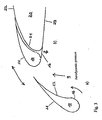
- FIG. 9 shows a schematic cross-sectional view of a wing of an aircraft with a mainplane 20 and an additional airfoil 70 which is articulated on the mainplane, according to a further exemplary embodiment of the invention.
- the wing is formed from a mainplane 20 which has an upper face 22, a lower face 23 and an aerodynamically shaped rear end, or, in general, a rear-face area 25 facing away from the flow, with respect to the correct flow direction S.
- An additional airfoil 70 in the form of a high-lift flap for example, a Fowler flap which is well known in its own right from the prior art, is arranged on the rear face of the mainplane 20 and is coupled to the mainplane 20.
- This flap has an aerodynamically shaped nose facing the rear-face area 25 of the mainplane 20 or, more generally a nose area 71 and can be moved between a retracted state and an extended state, with a slot area or slot 79 being opened between the rear-face area 25 of the mainplane 20 and the nose area 71 of the additional airfoil 70.
- a variable shape slot-varying apparatus or a sealing element 76 is arranged on the rear face of the mainplane 20 and, when the additional airfoil 70 is extended, forms part of the aerodynamic profile of the mainplane 20, and at least partially covers the slot area 79 between the mainplane 20 and the additional airfoil 70 on the lower face when the additional airfoil 70 is in the retracted state.
- the slot-varying apparatus or the sealing element 76 is arranged at the transition between the lower face 23 and the rear face or rear-face area 25 of the mainplane 20, and can be varied or moved between a retracted state, contact state or a curved state, in which the slot-varying apparatus 76 forms a part of the aerodynamic profile of the mainplane 20 with a curved transition from the lower face 23 to the rear-face area 25 of the mainplane 20 when the additional airfoil 70 is extended, and an extended state in which the slot-bearing apparatus 76 at least partially covers the slot area 79 between the lower faces 23, 23a of the mainplane 20 and of the additional airfoil 70 when the additional airfoil 70 is in the retracted state.
- the slot-influencing state may in particular be a slot-closing state, in which the slot-varying apparatus closes the slot 9.
- the front end 76a of the slot-varying apparatus 76 seen in the flow direction S or the profile chord direction, is fixed to the mainplane 20.
- the slot-varying apparatus 76 may be designed to be elastically flexible at least in places in the profile chord direction of the wing, and may have flexibly variable curvature.
- the slot-varying apparatus may also be in the form of a rigid part which can rotate or can be retracted and extended.
- the slot-varying apparatus 76 may be mounted at its front end 76a with respect to the mainplane 20 such that it can rotate about the span direction, so that its rear end 76b may assume various positions, depending on the movement state of the slot-varying apparatus.
- the slot-varying apparatus it is possible to provide for the slot-varying apparatus to form a transition, which is designed to be curved, for example, when the additional airfoil 70 is extended, from the lower face 23 to the rear face area 23 of the mainplane 20 when the additional airfoil 70 is extended.
- the slot-varying apparatus it is possible to provide for the slot-varying apparatus to have a curved shape in this state.
- the slot-varying apparatus 76 may be variable between the curved configuration and the extended configuration by means of aerodynamic forces acting between the mainplane 20 and the additional airfoil 70.
- the slot-varying apparatus 76 may be variable between the curved configuration and the extended configuration by means of a drive device 5 which is coupled to it.
- the drive device 5 may be arranged in the sealing element 76, for example, in the slat part 78b of the sealing element 76 which forms the curved transition from the lower face 23 to the rear-face area 25 of the mainplane 20 in a similar manner to that in the exemplary embodiments in Figures 4b and 5 .
- the drive apparatus can drive the slot-varying apparatus 76 on the basis of kinematic coupling of the extended and retracted state of the additional airfoil 70 to the movement state of the mainplane 20 in the sense of positive movement of the slot-varying apparatus 76 for example by the drive apparatus being kinematically coupled to a rail (flap track) by means of which the additional airfoil 70 is articulated on the mainplane 20.
- the rear-face area 12 of the additional airfoil 10 and the rear-face area 25 of the mainplane 20 are provided with a continuous contour without any sudden changes by virtue of the sealing element 16; 26; 36; 46; 76 which is designed to be curved when the additional airfoil 10 or 70 is in the extended state, thus considerably reducing the formation of noise-generating vortices in comparison to conventional rear-face contours without any concave taper (not without sudden changes), for example as known from DE 10 2004 056 537 A1 and normally referred to as a "slat hook".
- the drive apparatus for the slot-varying apparatus 16; 26; 36; 46 may be structurally integrated in the slot-varying apparatus.
- the drive apparatus may be formed from one or more piezo-actuators which are fitted on one surface or on two surfaces which extend in the longitudinal direction L of the slot-varying apparatus and are opposite one another.
- the slot-varying apparatus is designed to be flexible such that appropriately fitted piezo-actuators which are designed for the actuating modes of contraction and elongation can vary the shape and in particular the camber of the slot-varying apparatus in its longitudinal direction L.
- the piezo-actuators may, for example, be in the form of piezo-ceramic films, thin plates, wafers or fibers, including piezo-ceramic fibers with an interdigital electrode.
- a plurality of piezo-actuators in the form of plates may also be arranged in a plurality of discrete layers stacked one above the other and may be prefabricated to form a flat actuator step, in the form of plates (as a multilayer structure or in a bimorphous form).
- the piezo-actuators which are arranged in layers one above the other may also be in the form of quickpacks which are based on the piezo-electric d31 effect, or stack actuators which are based on the piezo-electric d33 effect.
- the at least one piezo-actuator can be actively driven via a control device 6, or the piezo-actuators may be in the form of a passive circuit with the shape change of the slot-varying apparatus being produced on the basis of a movement, that is to say amplifying and/or continuing an initial movement.
- the passive circuit may be formed without a control device 6 or with it, for example as a safety function.
- the piezo-actuators and the circuit coupled to them are designed such that they send drive signals to at least some of the piezo actuators during their expansion on the basis of an initial movement in a retraction or extension direction of the slot-varying apparatus, in order to operate them in the sense of continuing in the initially detected movement of the slot-varying apparatus.
- the piezo-actuators may also have an actuating-movement enhancement element, for example, an appropriate rod which appropriately transforms the deflections of the piezo-actuators.
- the drive apparatus may be part of an operating apparatus 4 (operating device) which has a control device 6 for driving the drive apparatus 5.
- the drive apparatus 5 receives a command signal in the control device 6, the magnitude of which signal corresponds to a movement state of the slot-varying apparatus.
- the operating device 4 includes a control device 6 and actuation devices 5a, 5b.
- the operating device 4 is functionally integrated with an aircraft system which are functional modules, for example realized by a software module, by hardware implemented functions (like ASICs) or by a computer module comprising these functions as software modules implemented therein.
- the operating device 4 with the control device 6 can be structurally integrated in the wing or in the fuselage as part of an aircraft electronic system.
- the control device 6 comprises an actuation command function which is functionally connected and preferably in communication with the first actuation device 5a for generating a signal for actuation of the auxiliary flap 10, 70 and with the second actuation device 5b for generating a signal for actuation of the slot opening and closing device 16; 26; 36; 46 (slot varying apparatus).
- the first actuation device 5a and the second actuation device 5b can be integrated in one actuation device 5. Accordingly, the control device 6 is connected by a first command line 8a to the first actuation device 5a for driving or moving the auxiliary flap 10, 70 and with a second command line 8b to the second actuation device 5b for driving the slot opening and closing device 16; 26; 36; 46.
- the first command line 8a and the second command line 8b can be a bus line for transmitting digital command signals or can be an analogue signal line.
- the actuation devices 5, 5a, 5b actuate the flap 10, 70 and the slot opening and closing device 16; 26; 36; 46, respectively, wherein the actuation devices can be powered electrically or hydraulically, if appropriate.
- the aircraft can comprise one flap 10, 70 or several flaps 10, 70 and one or several slot opening and closing devices 16; 26; 36; 46 on each wing.
- the control device 6 and the first and second actuation device can be related to the one flap 10, 70 or to several flaps on both wings so that the flaps and the slot opening and closing devices 16; 26; 36; 46 on both wings are controlled by the first and second actuation device, respectively.
- the operating device 4 can be configured such that the first and second actuation device are functionally coupled
- first and second actuation devices can be provided for actuating several flaps and slot opening and closing devices on both wings or several groups of flaps and a slot opening and closing device on both wings.
- the signals for actuation of the first and second actuation device can be generated, measured or calculated by an actuation command function of the control device upon operational data received by the actuation command function from another aircraft system device or operational data generated by the actuation command function itself.
- These operational data can for example be data describing or defining a flight state or an operational system mode like landing, approach or start.
- these operational data or part of these operational data are generated, measured or calculated by the control device or by an another aircraft system and transmitted to the control device 6 from another system device functionally and/or located externally with regard to the operating device 4, like another aircraft system device, the autopilot or a manual input device for example a man-machine interface (MMI), a pilot's control device, the primary flight system, the secondary flight system and the navigation system.
- MMI man-machine interface
- operational data are transmitted to the actuation command function of the control device 6.
- the command function calculates positions of the flap 10, 70 and of the slot opening and closing device 16; 26; 36; 46 and sends these to the first actuation device 5a and to the second actuation device 5b which actuate the flap 10, 70 and slot opening and closing device 16; 26; 36; 46, respectively.
- this command function can be integrated in another aircraft system device outside the operating system 4, so that the operating system receives the desired or nominal positions of the flap 10, 70 and of the slot opening and closing device 16; 26; 36; 46 and transfers these positions with or without changes to the actuation devices 5a, 5b for actuating the flap and of the slot opening and closing device, respectively.
- control device comprises a command function which is designed to receive from an aircraft system device operational data, for example data describing or defining the flight state, a maneuver or an operational system mode like landing, approach or start or a phase thereof.
- the command function generates desired or nominal positions of the flap and/or of the slot opening and closing device.
- the command function can comprise a table in which pre-defined operational data are set in relation to desired or nominal positions of the flap and/or of the slot opening and closing device.
- the command function With the operational data as input, the command function generates or identifies the desired or nominal positions of the flap and/or of the slot opening and closing device for the instant flight situation and/or system state and sends these position data to the first and second actuation device which actuate the flap and the slot opening and closing device, respectively.
- a function can be integrated in the command function which, based on flight data like altitude and/or speed and/or based on aircraft system data like safety-related data (for example failure degradation in the slat or flap system or another system), generates further nominal positions of the flap and/or of the slot opening and closing device for the instant flight situation which are transmitted to the first and second actuation device which actuate the flan and the slot opening and closing device, respectively.
- the command function can be designed such that, during an operational system mode, for example start or landing, when the aircraft reaches a pre-defined flight state, like a pre-defined position and/or speed and/or altitude, the command function generates a command to the flap and/or the slot opening and closing device if the actual flight state value reaches or exceeds a pre-defined value which is determined by a comparison function.
- This function can be implemented in order to comply with noise and/or safety requirements and particularly in order to increase safety in critical flight phases.
- the slot opening and closing device can be commanded dependent on the position of the flap 10, 70 to extend the slot opening and closing device 16; 26; 36; 46 when the flap 10 is in its retracted position ( Figure 1b ).
- a function can be provided in the actuation command function which stops the actuation of the flap and/or the slot opening and closing device, if a corresponding value is received by the operating device by another aircraft system device, for example for safety reasons.
- the command function can be designed such that it generates the command signals in discrete steps or continuously according to the situations described above.
- the first and optionally the second actuation device can generally be coupled to at least one position sensor for measuring the position of the flap and optionally one position sensor of the slot opening and closing device.
- the position sensor measures the actual position of the flap and/or the slot opening and closing device, respectively, and sends the actual position as feedback to the first and second actuation device.
- For failure detection a comparison of the nominal or desired value and the actual value is made in the corresponding actuation device 5a, 5b, or in the control device or in another module of the operating device 5 or in another aircraft system device. Based on the result of this comparison, the control device can receive or generate a fail safe command, for example not to actuate the flap and/or the slot opening and closing device.
- the control device can be located close to the actuation devices 5a, 5b.
- the control device or a part thereof can be functionally connected to actuation devices 5a, 5b for transmitting the first and second, respectively, actuation command signals ("smart actuation device").
- actuation command signals "smart actuation device"
- a digital bus line connects the actuation devices with a control function of the control device which generates a desired value or nominal position value of the flap and the slot opening and closing device, respectively.
- the command function can be configured such that it generates command signals by which the slot 9 is opened at a speed which is higher than the speed at which the flap 2 is itself extended.
- the slot 9 can be opened by rotating or tilting the slot opening and closing device 16; 26; 36; 46 about an axis which runs in the wingspan direction, for example, as is illustrated in figures 4 to 8 , or by changing the shape of the slot opening and closing device 16; 26; 36; 46, for example as shown in Figure 1 or by extending or retracting a slot opening and closing device 16; 26; 36; 46 through an opening in the flap 10, 70.
- the slot 3 can be opened by an actuation device 5 which can be operated independently of or dependent on the position of the flap 2.
- the actuation device 5 may be operated by a motor or motors.
- the actuation device 5 may be operated by spring force or by elastic deformation of components contained in it.
- the slot 3 can also be opened by aerodynamic forces.
- the opening of the slot 3 can be enabled in response to an externally supplied signal, for example by releasing a catch or some other lock, and the slot 3 can be closed by a motor or motors.
Claims (18)
- Aile d'avion, présentant :■ un plan principal (20) comprenant une face supérieure (22), une face inférieure (23) et une zone avant (21) faisant face à l'écoulement (S),■ un profil d'aile portante supplémentaire (10) qui est articulé sur le plan principal (20) et présente une zone avant (11) faisant face à l'écoulement (S) et une zone arrière (12) faisant face à la zone avant (21) du plan principal (20), et qui peut être déplacé entre un état rétracté et un état étendu avec une fente (9) entre la zone avant (21) du plan principal (20) et la zone arrière (12) du profil d'aile portante supplémentaire (10) en train d'être changé, et■ un appareillage de variation de fente (16; 26; 36; 46) qui est agencé sur la face inférieure du profil d'aile portante supplémentaire (10), s'étend le long du contour du profil d'aile portante supplémentaire lorsque le profil d'aile portante supplémentaire (10) est étendu, et couvre au moins en partie la zone de fente (9) entre le plan principal (20) et le profil d'aile portante supplémentaire (10) sur la face inférieure lorsque le profil d'aile portante supplémentaire (10) est dans l'état rétracté,dans lequel l'appareillage de variation de fente (16; 26; 36; 46) est agencé sur la transition entre la zone avant (11) et la zone arrière (12) du profil d'aile portante supplémentaire (10) et peut être changé entre une configuration incurvée dans laquelle lorsque le profil d'aile portante supplémentaire (10) est étendu, il fait partie de son profil aérodynamique avec une transition incurvée depuis la zone avant (11) vers la zone arrière (12) du profil d'aile portante supplémentaire (10), et une configuration étendue dans laquelle lorsque le profil d'aile portante supplémentaire (10) est rétracté, il couvre en partie la zone de fente (9) entre le plan principal (20) et le profil d'aile portante supplémentaire (10) sur la face inférieure,
caractérisée en ce que
l'appareillage de variation de fente (16; 26; 36; 46) est conçu pour être élastiquement flexible au moins en des endroits dans la direction de la corde du profil de l'aile ou en ce que l'appareillage de variation de fente (16) présente une courbure de flexion variable. - Aile selon la revendication 1, caractérisée en ce que l'appareillage de variation de fente (16; 26; 36; 46) peut être changé entre la configuration incurvée et la configuration étendue par des forces aérodynamiques agissant entre le plan principal (20) et le profil d'aile portante supplémentaire (10).
- Aile selon la revendication 1ou 2, caractérisée en ce que l'appareillage de variation de fente (16 ; 26 ; 36 ; 46) peut être changé entre la configuration incurvée et la configuration étendue au moyen d'un dispositif d'entraînement (17 ; 27 ; 37 ; 47) couplé à l'appareillage de variation de fente (16 ; 26 ; 36 ; 46).
- Aile selon la revendication 3, caractérisée en ce que le dispositif d'entraînement (37) est agencé dans l'appareillage de variation de fente (26).
- Aile selon la revendication 4, caractérisée en ce que le dispositif d'entraînement (37) est agencé dans la partie incurvée (28) de l'appareillage de variation de fente (26) qui forme la transition incurvée depuis la zone avant (11) vers la zone arrière (12) du profil d'aile portante supplémentaire (10).
- Aile selon la revendication 3, 4 ou 5, caractérisée en ce que le dispositif d'entraînement (47) est couplé cinématiquement au mouvement du profil d'aile portante supplémentaire (10) par rapport au plan principal (20) dans le sens de mouvement positif de l'appareillage de variation de fente (46) pendant l'extension et la rétraction du profil d'aile portante supplémentaire (10).
- Aile selon la revendication 6, caractérisée en ce que le dispositif d'entraînement (47) est couplé cinématiquement à un rail au moyen duquel le profil d'aile portante supplémentaire (10) est articulé sur le plan principal (20).
- Aile d'avion, comprenant un plan principal (20) ayant une face supérieure (22), une face inférieure (23) et une zone arrière de forme aérodynamique (25), un profil d'aile portante supplémentaire (70) agencé sur la face arrière du plan principal (20) et articulé sur le plan principal (20), une zone avant de forme aérodynamique (71) faisant face à la zone arrière (25) du plan principal (20), et qui est mobile entre un état rétracté et un état étendu ouvrant une zone de fente (79) entre la zone arrière (25) du plan principal (20) et la zone avant (71) du profil d'aile portante supplémentaire (70), l'aile comprenant un appareillage de variation de fente (76) agencé sur la face arrière du plan principal (20) et, lorsque le profil d'aile portante (70) supplémentaire est étendu, il fait partie du profil aérodynamique du plan principal (20) et, lorsque le profil d'aile portante supplémentaire (70) est rétracté, il couvre au moins en partie la zone de fente (79) entre le plan principal (20) et le profil d'aile portante supplémentaire (70) sur la face inférieure, l'appareillage de variation de fente (76) étant agencé sur la transition entre la face inférieure (23) et la zone arrière (25) du plan principal (20) et peut être changé entre une configuration incurvée dans laquelle il fait partie du profil aérodynamique du plan principal (20) sur la transition incurvée depuis la face inférieure (23) vers la zone arrière (25) du plan principal (20) lorsque le profil d'aile portante supplémentaire (70) est étendu et, en configuration étendue dans laquelle il couvre en partie la zone de fente (79) entre le plan principal (20) et le profil d'aile portante supplémentaire (70) sur la face inférieure lorsque le profil d'aile portante supplémentaire (70) est rétracté,
caractérisé en ce que
l'appareillage de variation de fente (76) est conçu pour être élastiquement flexible au moins en des endroits dans la direction de la corde du profil de l'aile ou en ce que l'appareillage de variation de fente (76) présente une courbure de flexion variable. - Aile selon la revendication 8, caractérisée en ce que l'appareillage de variation de fente (76) peut être changé entre la configuration incurvée et la configuration étendue par des forces aérodynamiques agissant entre le plan principal (20) et le profil d'aile portante supplémentaire (10).
- Aile selon l'une des revendications 8 ou 9, caractérisée en ce que l'appareillage de variation de fente (76) peut être changé entre la configuration incurvée et la configuration étendue au moyen d'un dispositif d'entraînement couplé à l'appareillage de variation de fente.
- Aile selon la revendication 10, caractérisée en ce que le dispositif d'entraînement est agencé dans l'appareillage de variation de fente (76).
- Aile selon la revendication 11, caractérisée en ce que le système d'entraînement est agencé dans la partie incurvée (78b) de l'appareillage de variation de fente (76) qui forme la transition incurvée depuis la zone avant (23) vers la zone arrière (25) du plan principal (20).
- Aile selon la revendication 10, 11 ou 12, caractérisée en ce que le dispositif d'entraînement est couplé cinématiquement au mouvement du profil d'aile portante supplémentaire (70) par rapport au plan principal (20) dans le sens de mouvement positif de l'appareillage de variation de fente (76) pendant l'extension et la rétraction du profil d'aile portante supplémentaire (70).
- Aile selon la revendication 13, caractérisée en ce que le dispositif d'entraînement est couplé cinématiquement à un rail au moyen duquel le profil d'aile portante supplémentaire (70) est articulé sur le plan principal (20).
- Aile selon l'une des revendications 1 à 14, caractérisée en ce que le dispositif d'actionnement (4) est prévu pour actionner le dispositif d'ouverture et de fermeture de fente (16; 26; 36; 46) comprenant un dispositif de commande (6) utilisé pour ouvrir la fente (9) par laquelle l'écoulement passe, en fonction de l'angle d'attaque ou de la vitesse, ou en fonction d'un paramètre équivalent à l'angle d'attaque ou à la vitesse.
- Aile selon l'une des revendications 1 à 7, caractérisée en ce que le volet est un bec de bord d'attaque d'aile.
- Aile selon l'une des revendications 8 à 15, caractérisée en ce que le volet hypersustentateur est un volet de bord de fuite.
- Aile selon l'une des revendications 1 à 15, caractérisée en ce que l'aile comprend un dispositif d'actionnement (4) comprenant un dispositif de commande (6) et des dispositifs de déclenchement (5a, 5b), dans lequel le dispositif de commande (6) est relié par une première ligne de commande (8a) à un premier dispositif de déclenchement (5a) pour entraîner un volet (2) et par une deuxième ligne de commande (8b) à un deuxième dispositif de déclenchement (5b) pour entraîner un dispositif d'ouverture et de fermeture de fente, le dispositif de commande (6) comprenant une fonction pour générer un signal de déclenchement du premier dispositif de déclenchement (5a) et pour générer un signal de déclenchement du deuxième dispositif de déclenchement (5b).
Applications Claiming Priority (2)
| Application Number | Priority Date | Filing Date | Title |
|---|---|---|---|
| DE102006058650A DE102006058650B4 (de) | 2006-12-11 | 2006-12-11 | Tragflügel eines Flugzeugs |
| PCT/EP2007/010831 WO2008071399A1 (fr) | 2006-12-11 | 2007-12-11 | Aile d'aéronef |
Publications (2)
| Publication Number | Publication Date |
|---|---|
| EP2091812A1 EP2091812A1 (fr) | 2009-08-26 |
| EP2091812B1 true EP2091812B1 (fr) | 2010-10-06 |
Family
ID=39228641
Family Applications (1)
| Application Number | Title | Priority Date | Filing Date |
|---|---|---|---|
| EP07856579A Not-in-force EP2091812B1 (fr) | 2006-12-11 | 2007-12-11 | Aile d'aeronef |
Country Status (10)
| Country | Link |
|---|---|
| US (1) | US8191835B2 (fr) |
| EP (1) | EP2091812B1 (fr) |
| JP (1) | JP2010512274A (fr) |
| CN (1) | CN101588964B (fr) |
| AT (1) | ATE483627T1 (fr) |
| BR (1) | BRPI0720267A2 (fr) |
| CA (1) | CA2672068A1 (fr) |
| DE (2) | DE102006058650B4 (fr) |
| RU (1) | RU2009126419A (fr) |
| WO (1) | WO2008071399A1 (fr) |
Families Citing this family (16)
| Publication number | Priority date | Publication date | Assignee | Title |
|---|---|---|---|---|
| DE102008050544A1 (de) * | 2008-10-06 | 2010-04-29 | Airbus Deutschland Gmbh | An der Tragfläche eines Flugzeugs angeordneter Vorflügel |
| US8534611B1 (en) | 2009-07-17 | 2013-09-17 | The Boeing Company | Moveable leading edge device for a wing |
| US8534610B1 (en) | 2009-07-17 | 2013-09-17 | The Boeing Company | Method and apparatus for a leading edge slat on a wing of an aircraft |
| US9327824B2 (en) | 2010-12-15 | 2016-05-03 | The Boeing Company | Adjustment of wings for variable camber for optimum take-off and landing |
| DE102011018907A1 (de) * | 2011-04-28 | 2012-10-31 | Airbus Operations Gmbh | Hochauftriebskomponente für ein Flugzeug, Hochauftriebssystem, Verfahren zum Beeinflussen der Hochauftriebseigenschaften eines Flugzeugs und Flugzeug |
| CN102417031A (zh) * | 2011-10-20 | 2012-04-18 | 南京航空航天大学 | 大攻角非对称涡合成射流非定常小扰动控制装置 |
| US9016637B2 (en) * | 2012-02-10 | 2015-04-28 | The Boeing Company | High-positioned 3-position variable camber krueger |
| JP6426451B2 (ja) * | 2014-12-03 | 2018-11-21 | マツダ株式会社 | 自動車内外装部品 |
| US11492096B2 (en) * | 2017-09-01 | 2022-11-08 | Embraer S.A. | Retractable leading edge wing slats having autonomously curvable airflow shield for noise-abatement |
| JP6968003B2 (ja) * | 2018-03-07 | 2021-11-17 | 三菱重工業株式会社 | 高揚力装置及び航空機の翼 |
| EP3847938A1 (fr) * | 2020-01-09 | 2021-07-14 | Koninklijke Philips N.V. | Tube plongeur pour séparateur cyclonique |
| WO2020169752A1 (fr) * | 2019-02-20 | 2020-08-27 | Koninklijke Philips N.V. | Viseur de tourbillon pour un séparateur cyclonique |
| CN111924086B (zh) * | 2020-07-07 | 2021-12-10 | 北京机电工程研究所 | 一种记忆合金驱动的可变形机构 |
| CN114506460A (zh) * | 2022-03-15 | 2022-05-17 | 中国商用飞机有限责任公司 | 用于监测襟翼故障的系统及方法 |
| CN114684353B (zh) * | 2022-06-02 | 2022-10-14 | 中国空气动力研究与发展中心低速空气动力研究所 | 一种脉冲射流激励器、机翼和飞行器 |
| CN115027663B (zh) * | 2022-08-10 | 2022-11-22 | 中国空气动力研究与发展中心计算空气动力研究所 | 一种通过射流实现的机翼融合控制方法 |
Family Cites Families (11)
| Publication number | Priority date | Publication date | Assignee | Title |
|---|---|---|---|---|
| US2381678A (en) * | 1942-02-11 | 1945-08-07 | Frank R Maxwell | Airplane wing |
| US3129907A (en) * | 1960-08-18 | 1964-04-21 | Dornier Werke Gmbh | Airplane wing flap |
| GB2003098B (en) | 1977-07-07 | 1982-01-27 | British Aircraft Corp Ltd | Aircraft wings |
| DE3114143A1 (de) * | 1981-04-08 | 1982-10-28 | Vereinigte Flugtechnische Werke Gmbh, 2800 Bremen | "verfahren zur optimierung des reiseflugzustandes von flugzeugen mit transsonischen tragfluegeln sowie vorrichtung zur durchfuehrung des verfahrens" |
| US5209438A (en) * | 1988-06-20 | 1993-05-11 | Israel Wygnanski | Method and apparatus for delaying the separation of flow from a solid surface |
| US6171056B1 (en) * | 1998-12-23 | 2001-01-09 | Sikorsky Aircraft Corporation | Technique for providing a signal for controlling blade vortex interaction noise of a rotorcraft |
| DE19925560B4 (de) * | 1999-06-04 | 2004-04-22 | Deutsches Zentrum für Luft- und Raumfahrt e.V. | Zusatzflügel für Hauptflügel von Flugzeugen |
| US6837465B2 (en) * | 2003-01-03 | 2005-01-04 | Orbital Research Inc | Flow control device and method of controlling flow |
| GB0405843D0 (en) * | 2004-03-16 | 2004-04-21 | Westland Helicopters | Improvements in or relating to aerofoils |
| DE102004056537B4 (de) * | 2004-11-23 | 2010-09-09 | Eads Deutschland Gmbh | Anordnung zur Minderung des aerodynamischen Lärms an einem Zusatzflügel eines Flugzeuges |
| DE102005018427A1 (de) * | 2005-04-21 | 2006-11-02 | Deutsches Zentrum für Luft- und Raumfahrt e.V. | Auftriebsfläche mit verbessertem Ablöseverhalten bei stark veränderlichem Anstellwinkel |
-
2006
- 2006-12-11 DE DE102006058650A patent/DE102006058650B4/de not_active Expired - Fee Related
-
2007
- 2007-12-11 EP EP07856579A patent/EP2091812B1/fr not_active Not-in-force
- 2007-12-11 CN CN2007800457320A patent/CN101588964B/zh not_active Expired - Fee Related
- 2007-12-11 DE DE602007009720T patent/DE602007009720D1/de active Active
- 2007-12-11 CA CA002672068A patent/CA2672068A1/fr not_active Abandoned
- 2007-12-11 BR BRPI0720267-9A patent/BRPI0720267A2/pt not_active IP Right Cessation
- 2007-12-11 JP JP2009540653A patent/JP2010512274A/ja active Pending
- 2007-12-11 WO PCT/EP2007/010831 patent/WO2008071399A1/fr active Application Filing
- 2007-12-11 RU RU2009126419/11A patent/RU2009126419A/ru not_active Application Discontinuation
- 2007-12-11 AT AT07856579T patent/ATE483627T1/de not_active IP Right Cessation
- 2007-12-11 US US12/448,142 patent/US8191835B2/en active Active
Also Published As
| Publication number | Publication date |
|---|---|
| US8191835B2 (en) | 2012-06-05 |
| BRPI0720267A2 (pt) | 2014-01-28 |
| CN101588964A (zh) | 2009-11-25 |
| CA2672068A1 (fr) | 2008-06-19 |
| US20100019095A1 (en) | 2010-01-28 |
| DE102006058650A1 (de) | 2008-06-12 |
| DE602007009720D1 (de) | 2010-11-18 |
| EP2091812A1 (fr) | 2009-08-26 |
| DE102006058650B4 (de) | 2009-11-19 |
| ATE483627T1 (de) | 2010-10-15 |
| RU2009126419A (ru) | 2011-01-20 |
| CN101588964B (zh) | 2011-06-08 |
| JP2010512274A (ja) | 2010-04-22 |
| WO2008071399A1 (fr) | 2008-06-19 |
| WO2008071399B1 (fr) | 2008-07-31 |
Similar Documents
| Publication | Publication Date | Title |
|---|---|---|
| EP2091812B1 (fr) | Aile d'aeronef | |
| US8382044B2 (en) | High-lift system on the wing of an aircraft, and method for its operation | |
| US8783623B2 (en) | Device for the generation of aerodynamic vortices and also a regulating flap and wing with a device for the generation of aerodynamic vortices | |
| US8622350B1 (en) | Compound leading edge device for aircraft | |
| EP2524865B1 (fr) | Ensemble d'aile d'avion | |
| US5294080A (en) | Lift enhancing tabs for airfoils | |
| US6364254B1 (en) | Aircraft airfoil with close-mounted engine and leading edge high lift system | |
| US7258308B2 (en) | Method and apparatus for controlling airflow with a gapped trailing edge device having a flexible flow surface | |
| EP2214959B1 (fr) | Système d'actionnement pour dispositif hypersustentateur de bord d'attaque | |
| EP2851287B1 (fr) | Système d'actionneur de bord de fuite et procédé associé | |
| US7048235B2 (en) | Slotted aircraft wing | |
| EP1488998B1 (fr) | Dispositif de contrôle du bord de fuite d'une aile | |
| CN108082453B (zh) | 飞行器气流改变装置和用于飞行器的旋涡发生器结构 | |
| WO2004041640A2 (fr) | Aile d'aeronef comportant des fentes | |
| EP0100775B1 (fr) | Volet de bord d'attaque | |
| JP2010512274A5 (fr) | ||
| US20190263505A1 (en) | Actuatable aircraft component | |
| EP2516260B1 (fr) | Système hypersustentateur pour aéronef | |
| US8141815B1 (en) | Wing strut trailing edge device | |
| US10967957B2 (en) | Methods and apparatus to extend a leading-edge vortex of a highly-swept aircraft wing | |
| EP3498595A1 (fr) | Mini-volets de croisière pour aéronef | |
| GB2553847A (en) | Variable chord length flight control surfaces |
Legal Events
| Date | Code | Title | Description |
|---|---|---|---|
| PUAI | Public reference made under article 153(3) epc to a published international application that has entered the european phase |
Free format text: ORIGINAL CODE: 0009012 |
|
| 17P | Request for examination filed |
Effective date: 20090604 |
|
| AK | Designated contracting states |
Kind code of ref document: A1 Designated state(s): AT BE BG CH CY CZ DE DK EE ES FI FR GB GR HU IE IS IT LI LT LU LV MC MT NL PL PT RO SE SI SK TR |
|
| GRAP | Despatch of communication of intention to grant a patent |
Free format text: ORIGINAL CODE: EPIDOSNIGR1 |
|
| DAX | Request for extension of the european patent (deleted) | ||
| GRAS | Grant fee paid |
Free format text: ORIGINAL CODE: EPIDOSNIGR3 |
|
| RAP1 | Party data changed (applicant data changed or rights of an application transferred) |
Owner name: AIRBUS OPERATIONS GMBH |
|
| GRAA | (expected) grant |
Free format text: ORIGINAL CODE: 0009210 |
|
| AK | Designated contracting states |
Kind code of ref document: B1 Designated state(s): AT BE BG CH CY CZ DE DK EE ES FI FR GB GR HU IE IS IT LI LT LU LV MC MT NL PL PT RO SE SI SK TR |
|
| REG | Reference to a national code |
Ref country code: GB Ref legal event code: FG4D |
|
| REG | Reference to a national code |
Ref country code: CH Ref legal event code: EP |
|
| REG | Reference to a national code |
Ref country code: IE Ref legal event code: FG4D |
|
| REF | Corresponds to: |
Ref document number: 602007009720 Country of ref document: DE Date of ref document: 20101118 Kind code of ref document: P |
|
| REG | Reference to a national code |
Ref country code: NL Ref legal event code: VDEP Effective date: 20101006 |
|
| PG25 | Lapsed in a contracting state [announced via postgrant information from national office to epo] |
Ref country code: SI Free format text: LAPSE BECAUSE OF FAILURE TO SUBMIT A TRANSLATION OF THE DESCRIPTION OR TO PAY THE FEE WITHIN THE PRESCRIBED TIME-LIMIT Effective date: 20101006 |
|
| LTIE | Lt: invalidation of european patent or patent extension |
Effective date: 20101006 |
|
| PG25 | Lapsed in a contracting state [announced via postgrant information from national office to epo] |
Ref country code: LT Free format text: LAPSE BECAUSE OF FAILURE TO SUBMIT A TRANSLATION OF THE DESCRIPTION OR TO PAY THE FEE WITHIN THE PRESCRIBED TIME-LIMIT Effective date: 20101006 |
|
| PG25 | Lapsed in a contracting state [announced via postgrant information from national office to epo] |
Ref country code: BG Free format text: LAPSE BECAUSE OF FAILURE TO SUBMIT A TRANSLATION OF THE DESCRIPTION OR TO PAY THE FEE WITHIN THE PRESCRIBED TIME-LIMIT Effective date: 20110106 Ref country code: SE Free format text: LAPSE BECAUSE OF FAILURE TO SUBMIT A TRANSLATION OF THE DESCRIPTION OR TO PAY THE FEE WITHIN THE PRESCRIBED TIME-LIMIT Effective date: 20101006 Ref country code: PT Free format text: LAPSE BECAUSE OF FAILURE TO SUBMIT A TRANSLATION OF THE DESCRIPTION OR TO PAY THE FEE WITHIN THE PRESCRIBED TIME-LIMIT Effective date: 20110207 Ref country code: AT Free format text: LAPSE BECAUSE OF FAILURE TO SUBMIT A TRANSLATION OF THE DESCRIPTION OR TO PAY THE FEE WITHIN THE PRESCRIBED TIME-LIMIT Effective date: 20101006 Ref country code: IS Free format text: LAPSE BECAUSE OF FAILURE TO SUBMIT A TRANSLATION OF THE DESCRIPTION OR TO PAY THE FEE WITHIN THE PRESCRIBED TIME-LIMIT Effective date: 20110206 Ref country code: LV Free format text: LAPSE BECAUSE OF FAILURE TO SUBMIT A TRANSLATION OF THE DESCRIPTION OR TO PAY THE FEE WITHIN THE PRESCRIBED TIME-LIMIT Effective date: 20101006 Ref country code: FI Free format text: LAPSE BECAUSE OF FAILURE TO SUBMIT A TRANSLATION OF THE DESCRIPTION OR TO PAY THE FEE WITHIN THE PRESCRIBED TIME-LIMIT Effective date: 20101006 Ref country code: NL Free format text: LAPSE BECAUSE OF FAILURE TO SUBMIT A TRANSLATION OF THE DESCRIPTION OR TO PAY THE FEE WITHIN THE PRESCRIBED TIME-LIMIT Effective date: 20101006 |
|
| PG25 | Lapsed in a contracting state [announced via postgrant information from national office to epo] |
Ref country code: BE Free format text: LAPSE BECAUSE OF FAILURE TO SUBMIT A TRANSLATION OF THE DESCRIPTION OR TO PAY THE FEE WITHIN THE PRESCRIBED TIME-LIMIT Effective date: 20101006 Ref country code: GR Free format text: LAPSE BECAUSE OF FAILURE TO SUBMIT A TRANSLATION OF THE DESCRIPTION OR TO PAY THE FEE WITHIN THE PRESCRIBED TIME-LIMIT Effective date: 20110107 |
|
| PG25 | Lapsed in a contracting state [announced via postgrant information from national office to epo] |
Ref country code: CZ Free format text: LAPSE BECAUSE OF FAILURE TO SUBMIT A TRANSLATION OF THE DESCRIPTION OR TO PAY THE FEE WITHIN THE PRESCRIBED TIME-LIMIT Effective date: 20101006 Ref country code: EE Free format text: LAPSE BECAUSE OF FAILURE TO SUBMIT A TRANSLATION OF THE DESCRIPTION OR TO PAY THE FEE WITHIN THE PRESCRIBED TIME-LIMIT Effective date: 20101006 Ref country code: ES Free format text: LAPSE BECAUSE OF FAILURE TO SUBMIT A TRANSLATION OF THE DESCRIPTION OR TO PAY THE FEE WITHIN THE PRESCRIBED TIME-LIMIT Effective date: 20110117 Ref country code: MC Free format text: LAPSE BECAUSE OF NON-PAYMENT OF DUE FEES Effective date: 20101231 |
|
| PLBE | No opposition filed within time limit |
Free format text: ORIGINAL CODE: 0009261 |
|
| STAA | Information on the status of an ep patent application or granted ep patent |
Free format text: STATUS: NO OPPOSITION FILED WITHIN TIME LIMIT |
|
| PG25 | Lapsed in a contracting state [announced via postgrant information from national office to epo] |
Ref country code: RO Free format text: LAPSE BECAUSE OF FAILURE TO SUBMIT A TRANSLATION OF THE DESCRIPTION OR TO PAY THE FEE WITHIN THE PRESCRIBED TIME-LIMIT Effective date: 20101006 Ref country code: PL Free format text: LAPSE BECAUSE OF FAILURE TO SUBMIT A TRANSLATION OF THE DESCRIPTION OR TO PAY THE FEE WITHIN THE PRESCRIBED TIME-LIMIT Effective date: 20101006 Ref country code: SK Free format text: LAPSE BECAUSE OF FAILURE TO SUBMIT A TRANSLATION OF THE DESCRIPTION OR TO PAY THE FEE WITHIN THE PRESCRIBED TIME-LIMIT Effective date: 20101006 Ref country code: DK Free format text: LAPSE BECAUSE OF FAILURE TO SUBMIT A TRANSLATION OF THE DESCRIPTION OR TO PAY THE FEE WITHIN THE PRESCRIBED TIME-LIMIT Effective date: 20101006 |
|
| 26N | No opposition filed |
Effective date: 20110707 |
|
| PG25 | Lapsed in a contracting state [announced via postgrant information from national office to epo] |
Ref country code: IE Free format text: LAPSE BECAUSE OF NON-PAYMENT OF DUE FEES Effective date: 20101211 |
|
| REG | Reference to a national code |
Ref country code: DE Ref legal event code: R097 Ref document number: 602007009720 Country of ref document: DE Effective date: 20110707 |
|
| PG25 | Lapsed in a contracting state [announced via postgrant information from national office to epo] |
Ref country code: IT Free format text: LAPSE BECAUSE OF NON-PAYMENT OF DUE FEES Effective date: 20101211 Ref country code: MT Free format text: LAPSE BECAUSE OF FAILURE TO SUBMIT A TRANSLATION OF THE DESCRIPTION OR TO PAY THE FEE WITHIN THE PRESCRIBED TIME-LIMIT Effective date: 20101006 |
|
| REG | Reference to a national code |
Ref country code: CH Ref legal event code: PL |
|
| PG25 | Lapsed in a contracting state [announced via postgrant information from national office to epo] |
Ref country code: CY Free format text: LAPSE BECAUSE OF FAILURE TO SUBMIT A TRANSLATION OF THE DESCRIPTION OR TO PAY THE FEE WITHIN THE PRESCRIBED TIME-LIMIT Effective date: 20101006 |
|
| PG25 | Lapsed in a contracting state [announced via postgrant information from national office to epo] |
Ref country code: LU Free format text: LAPSE BECAUSE OF NON-PAYMENT OF DUE FEES Effective date: 20101211 Ref country code: HU Free format text: LAPSE BECAUSE OF FAILURE TO SUBMIT A TRANSLATION OF THE DESCRIPTION OR TO PAY THE FEE WITHIN THE PRESCRIBED TIME-LIMIT Effective date: 20110407 |
|
| PG25 | Lapsed in a contracting state [announced via postgrant information from national office to epo] |
Ref country code: CH Free format text: LAPSE BECAUSE OF NON-PAYMENT OF DUE FEES Effective date: 20111231 Ref country code: LI Free format text: LAPSE BECAUSE OF NON-PAYMENT OF DUE FEES Effective date: 20111231 Ref country code: TR Free format text: LAPSE BECAUSE OF FAILURE TO SUBMIT A TRANSLATION OF THE DESCRIPTION OR TO PAY THE FEE WITHIN THE PRESCRIBED TIME-LIMIT Effective date: 20101006 |
|
| REG | Reference to a national code |
Ref country code: DE Ref legal event code: R082 Ref document number: 602007009720 Country of ref document: DE Representative=s name: UEXKUELL & STOLBERG, DE Ref country code: DE Ref legal event code: R082 Ref document number: 602007009720 Country of ref document: DE Representative=s name: BIRD & BIRD LLP, DE |
|
| REG | Reference to a national code |
Ref country code: FR Ref legal event code: PLFP Year of fee payment: 9 |
|
| REG | Reference to a national code |
Ref country code: DE Ref legal event code: R082 Ref document number: 602007009720 Country of ref document: DE Representative=s name: BIRD & BIRD LLP, DE |
|
| REG | Reference to a national code |
Ref country code: FR Ref legal event code: PLFP Year of fee payment: 10 |
|
| PGFP | Annual fee paid to national office [announced via postgrant information from national office to epo] |
Ref country code: GB Payment date: 20161222 Year of fee payment: 10 Ref country code: DE Payment date: 20161213 Year of fee payment: 10 |
|
| PGFP | Annual fee paid to national office [announced via postgrant information from national office to epo] |
Ref country code: FR Payment date: 20161222 Year of fee payment: 10 |
|
| PGFP | Annual fee paid to national office [announced via postgrant information from national office to epo] |
Ref country code: IT Payment date: 20161223 Year of fee payment: 10 |
|
| REG | Reference to a national code |
Ref country code: DE Ref legal event code: R119 Ref document number: 602007009720 Country of ref document: DE |
|
| GBPC | Gb: european patent ceased through non-payment of renewal fee |
Effective date: 20171211 |
|
| REG | Reference to a national code |
Ref country code: FR Ref legal event code: ST Effective date: 20180831 |
|
| PG25 | Lapsed in a contracting state [announced via postgrant information from national office to epo] |
Ref country code: FR Free format text: LAPSE BECAUSE OF NON-PAYMENT OF DUE FEES Effective date: 20180102 Ref country code: DE Free format text: LAPSE BECAUSE OF NON-PAYMENT OF DUE FEES Effective date: 20180703 Ref country code: IT Free format text: LAPSE BECAUSE OF NON-PAYMENT OF DUE FEES Effective date: 20171211 |
|
| PG25 | Lapsed in a contracting state [announced via postgrant information from national office to epo] |
Ref country code: GB Free format text: LAPSE BECAUSE OF NON-PAYMENT OF DUE FEES Effective date: 20171211 |