EP2091112A1 - Electricity supply system for light strips or lights - Google Patents
Electricity supply system for light strips or lights Download PDFInfo
- Publication number
- EP2091112A1 EP2091112A1 EP08008128A EP08008128A EP2091112A1 EP 2091112 A1 EP2091112 A1 EP 2091112A1 EP 08008128 A EP08008128 A EP 08008128A EP 08008128 A EP08008128 A EP 08008128A EP 2091112 A1 EP2091112 A1 EP 2091112A1
- Authority
- EP
- European Patent Office
- Prior art keywords
- profile
- current
- carrying
- power supply
- supply system
- Prior art date
- Legal status (The legal status is an assumption and is not a legal conclusion. Google has not performed a legal analysis and makes no representation as to the accuracy of the status listed.)
- Withdrawn
Links
Images
Classifications
-
- H—ELECTRICITY
- H01—ELECTRIC ELEMENTS
- H01R—ELECTRICALLY-CONDUCTIVE CONNECTIONS; STRUCTURAL ASSOCIATIONS OF A PLURALITY OF MUTUALLY-INSULATED ELECTRICAL CONNECTING ELEMENTS; COUPLING DEVICES; CURRENT COLLECTORS
- H01R25/00—Coupling parts adapted for simultaneous co-operation with two or more identical counterparts, e.g. for distributing energy to two or more circuits
- H01R25/14—Rails or bus-bars constructed so that the counterparts can be connected thereto at any point along their length
Landscapes
- Installation Of Bus-Bars (AREA)
- Arrangement Of Elements, Cooling, Sealing, Or The Like Of Lighting Devices (AREA)
Abstract
Description
Die Erfindung betrifft ein Stromführungssystem für Lichtbänder oder Leuchten. Als Lichtband wird beispielsweise eine bandartige Aneinanderreihung von Einzelleuchten bezeichnet. Hierbei weist ein Lichtband z.B. eine Länge ab 3 m auf. Innerhalb eines Lichtbandes ist auch die Verkabelung für die Energieversorgung der Leuchtmittel der Leuchten vorgesehen. Die Verkabelung kann auch zur Übertragung von Steuersignalen dienen. Eine durchgehende Verkabelung ermöglicht es, lediglich an einer Stelle das Lichtband mit Energie zu versorgen, an der es an die Gebäudeenergieversorgung angeschlossen wird. Die Erfindung ist aber auch nur bei einer Leuchte anwendbar.The invention relates to a power supply system for light bands or lights. As a light band, for example, a band-like juxtaposition of individual lights is called. Here, a light band comprises e.g. a length from 3 m up. Within a light strip, the wiring for the power supply of the lamps of the lights is provided. The wiring can also be used to transmit control signals. A continuous wiring makes it possible to supply the light band with energy only at one point, where it is connected to the building energy supply. The invention is also applicable only to a luminaire.
Derartige Lichtbänder oder Leuchten sind meist aus einer Tragschiene aufgebaut. Hierbei ist ein Grundprofil mit einem seitlichen Stegprofil vorgesehen, so dass die Tragschiene ein etwa U-förmiges Profil aufweist. Um Leuchten am Grundprofil anzubringen, sind Geräteträger vorgesehen, welche in das Grundprofil eingesetzt werden. An diesen Geräteträgern befinden sich Einrichtungen zum Betrieb der Leuchte bzw. deren Leuchtmittel. Beim Einsetzen der Geräteträger in das Grundprofil wird normalerweise zusätzlich oder auch gleichzeitig eine elektrische Verbindung zwischen den Einrichtungen zum Betrieb der Leuchte und der sich im Bereich der Tragschiene befindlichen Verkabelung hergestellt. Zum Anschluss der an dem Grundprofil verlegten Verkabelung an das Stromnetz der Gebäudeverkabelung sind entsprechende Anschlüsse vorhanden.Such light bands or lights are usually constructed from a mounting rail. Here, a basic profile is provided with a lateral web profile, so that the mounting rail has an approximately U-shaped profile. To attach lights to the base profile, equipment carriers are provided, which are used in the basic profile. On this equipment carriers are facilities for the operation of the lamp or its bulbs. When inserting the equipment carrier in the basic profile is usually additionally or simultaneously produced an electrical connection between the facilities for the operation of the lamp and located in the region of the mounting rail cabling. Corresponding connections are available for connecting the wiring routed to the basic profile to the power network of the building cabling.
Herkömmlicherweise wird die Energieversorgung, d.h. die Verkabelung, innerhalb des Lichtbandes durch fünf Einzelleiter beispielsweise aus Kupfer realisiert. An diese Leiter werden die drei Phasen, der Nullleiter und der Schutzleiter angeschossen. Da es sich um einzelne isolierte Drähte handelt, tritt ab einer gewissen Länge des Lichtbandes bzw. der Leuchten das Problem auf, dass die Drähte aus der Tragschiene, welche an der Decke befestigt ist, nach unten heraus- bzw. herabhängen. Hierdurch kann es vorkommen, dass die Drähte auf einem Geräteträger aufliegen, welcher durch das Leuchtmittel an der Leuchte erwärmt wird. Durch das Aufliegen auf dem warmen bzw. heißen Geräteträger werden die Leitungen beschädigt, so dass es zu Kurzschlüssen oder anderen Fehlern führen kann.Conventionally, the power supply, ie the wiring, realized within the light band by five individual conductors, for example made of copper. At these conductors, the three phases, the neutral and the protective conductor are shot. Since these are individual insulated wires, the problem occurs at a certain length of the light strip or lights that the wires from the mounting rail, which is fixed to the ceiling, hanging down or hang down. This may cause that the wires rest on a device carrier, which is heated by the lamp on the lamp. By lying on the warm or hot equipment carrier, the cables are damaged, so that it can lead to short circuits or other errors.
Des Weiteren ist es aus dem Stand der Technik bekannt, die einzelnen Drähte in konstanten Abständen mittels anschraubbaren Klemmen am Grundprofil der Tragschiene zu befestigen. Dies ist äußerst aufwändig und zeitintensiv. Allerdings hängen hierbei die Drähte zum Teil immer noch zwischen zwei Klemmen herunter.Furthermore, it is known from the prior art to attach the individual wires at constant intervals by means of screw-on terminals on the base profile of the mounting rail. This is extremely time-consuming and time consuming. However, some of the wires still hang down between two clamps.
Ein weiterer Nachteil der Verwendung von Drähten ist, dass sowohl zum Einspeisen der Energieversorgung auf die Drähte, wie auch zum Abnehmen der Energie von den Drähten spezielle Einspeiser- und Abnehmereinrichtungen auf den Drähten vorgesehen sein müssen. Speziell zum Abnehmen ist es dann erforderlich, dass auf dem Geräteträger ebenfalls eine Abnehmereinrichtung vorhanden ist. Dieser Geräteträger kann dann lediglich genau so auf die Tragschiene aufgesetzt werden, dass die beiden Einrichtungen zum Abnehmen miteinander in Kontakt treten. Hierdurch wird ein flexibles Anbauen des Geräteträgers an die Tragschiene verhindert. Das heißt, der Geräteträger kann nur an einer bestimmten Stelle an der Tragschiene eingesetzt oder angebaut werden, welche durch die Abnehmereinrichtung auf den Drähten und der Position der Abnehmereinrichtung auf den Geräteträger definiert wird.Another disadvantage of the use of wires is that both the feeding of the power supply to the wires and the removal of the energy from the wires require the provision of special feeding and picking devices on the wires. Especially for removing it is then necessary that on the equipment rack also a pickup device is present. This device carrier can then only be placed exactly on the mounting rail, that the two devices come to contact with each other in contact. As a result, a flexible mounting of the device carrier is prevented from the support rail. That is, the equipment carrier can be used or attached only at a certain point on the mounting rail, which is defined by the pickup device on the wires and the position of the pickup device on the equipment carrier.
Der Erfindung liegt die Aufgabe zugrunde, ein Stromführungssystem für Lichtbänder oder Leuchten zu schaffen, welches das Anbringen der Verkabelung für die Energieversorgung vereinfacht und die Ausfallwahrscheinlichkeit verringert.The invention has for its object to provide a power supply system for lighting strips or lights, which simplifies the attachment of the wiring for the power supply and reduces the probability of failure.
Die Aufgabe wird erfindungsgemäß durch ein Stromführungssystem mit den Merkmalen des Anspruchs 1 gelöst.The object is achieved by a current carrying system with the features of claim 1.
Weitere vorteilhafte Ausführungsformen sind in den abhängigen Ansprüchen, der Beschreibung sowie den Figuren und deren Beschreibung angegeben.Further advantageous embodiments are specified in the dependent claims, the description and the figures and their description.
Gemäß dem Anspruch 1 weist das erfindungsgemäße Stromführungssystem für Lichtbänder oder Leuchten ein Stromführungsprofil auf. Des Weiteren sind an dem seitlichen Stegprofil der Tragschiene und an den dem Stegprofil zugewandten Seiten des Stromführungsprofils zusammenwirkende Bereiche oder Teile mindestens einer Befestigungseinrichtung ausgebildet. Hierbei ist die Befestigungseinrichtung zur werkzeuglosen Befestigung des Stromführungsprofils an der Tragschiene ausgelegt.According to claim 1, the current-carrying system according to the invention for lighting strips or lights on a power supply profile. Furthermore, at the lateral web profile of the support rail and at the web profile side facing the current-carrying profile cooperating areas or parts of at least one fastening device educated. Here, the fastening device is designed for tool-free attachment of the current-carrying profile to the support rail.
Ein Grundgedanke der Erfindung kann darin gesehen werden, zur Energieversorgung bzw. Energieleitung nicht einzelne Drähte zu verwenden, sondern ein Stromführungsprofil. Dieses Profil kann beispielsweise in Form eines Breitbandkabels ausgeführt sein. Hierdurch wird die Handhabung der einzelnen stromführenden Leitungen für Lichtband oder eine Leuchte vereinfacht, da die Energieversorgung nicht mehr mittels Einzeldrähten realisiert ist, sondern mittels eines zusammenhängenden Gebildes, welches einfacher gehandhabt werden kann.A basic idea of the invention can be seen in the fact that it is not a question of using individual wires for the power supply or power line, but rather a current-carrying profile. This profile can for example be designed in the form of a broadband cable. As a result, the handling of the individual current-carrying lines for light band or a luminaire is simplified because the energy supply is no longer realized by means of individual wires, but by means of a coherent structure, which can be handled more easily.
Ein weiterer Aspekt der Erfindung kann darin gesehen werden, zur Befestigung des Stromführungsprofils an der Tragschiene an dem Stromführungsprofil selbst und an der Tragschiene Teile oder Bereiche von Befestigungseinrichtungen auszubilden. Mittels dieser zusammenwirkenden Teile oder Bereiche der Befestigungseinrichtungen ist es möglich, das Stromführungsprofil an der Tragschiene zu befestigen, ohne zusätzlich Schrauben oder Kleber zu verwenden.Another aspect of the invention can be seen to form parts or areas of fasteners for attachment of the current-carrying profile to the support rail on the current-carrying profile itself and on the mounting rail. By means of these cooperating parts or areas of the fastening devices, it is possible to attach the current-carrying profile to the mounting rail, without using additional screws or adhesive.
Grundsätzlich können die Bereiche oder Teile der Befestigungseinrichtung an einer beliebigen Stelle des Stromführungsprofils und der Tragschiene ausgebildet sein. Eine einfache Montage wird dadurch erreicht, dass Teile oder Bereiche der Befestigungseinrichtung an dem seitlichen Stegprofil der Tragschiene ausgebildet sind. Hiermit zusammenwirkende Bereiche oder Teile sind an den dem Stegprofil zugewandten Seiten des Stromführungsprofils ausgebildet. Diese so ausgebildete, mindestens eine Befestigungseinrichtung ist zur werkzeuglosen Montage des Stromführungsprofils an der Tragschiene vorgesehen. So werden die einzelnen Bereiche oder Teile der Befestigungseinrichtung so konzipiert, dass durch ein Einführen und Andrücken des Stromführungsprofils in die Tragschiene, das Stromführungsprofil durch die Bereiche oder Teile der Befestigungseinrichtung, welche an dem Stegprofil und dem Stromführungsprofil vorgesehen sind, in der Nähe des Grundprofils gehalten wird.In principle, the areas or parts of the fastening device can be formed at any point of the current-carrying profile and the mounting rail. A simple assembly is achieved in that parts or areas of the fastening device are formed on the lateral web profile of the support rail. Hereby cooperating areas or parts are formed on the web profile facing sides of the current-carrying profile. This so formed, at least one fastening device is provided for tool-free mounting of the current-carrying profile on the support rail. Thus, the individual areas or parts of the fastening device are designed so that held by inserting and pressing the current-carrying profile in the mounting rail, the current-carrying profile through the areas or parts of the fastening device, which are provided on the web profile and the current-carrying profile, in the vicinity of the base profile becomes.
In einer bevorzugten Ausführungsform weisen die zusammenwirkenden Bereiche der mindestens einen Befestigungseinrichtung eine form- und/oder kraftschlüssige Verbindung auf. Mittels einer derartigen Verbindung kann das Stromführungsprofil in der Tragschiene befestigt werden. Grundsätzlich ist es möglich, die Bereiche der mindestens einen Befestigungseinrichtung nur in bestimmten örtlich begrenzten Arealen des Stromführungsprofils und des Stegprofils auszubilden. Um jedoch ein Durchhängen des Stromführungsprofils zu verhindern, hat es sich als vorteilhaft herausgestellt, wenn die zusammenwirkenden Teile oder Bereiche der mindestens einen Befestigungseinrichtung im Wesentlichen über die gesamte Länge des Grundprofils und des Stromführungsprofils ausgebildet sind. Hierdurch wird erreicht, dass das Stromführungsprofil entlang der gesamten Länge des Grundprofils an der Tragschiene befestigt ist.In a preferred embodiment, the cooperating regions of the at least one fastening device have a positive and / or non-positive connection. By means of such a connection, the current-carrying profile can be secured in the mounting rail. In principle, it is possible, the areas of at least one fastening device only in certain localized areas of the current-carrying profile and the bar profile. However, in order to prevent sagging of the current-carrying profile, it has proven to be advantageous if the interacting parts or regions of the at least one fastening device are formed substantially over the entire length of the base profile and the current-carrying profile. This ensures that the current-carrying profile is attached along the entire length of the base profile to the support rail.
Die zusammenwirkenden Bereiche der mindestens einen Befestigungseinrichtung können als Ablenkkörper, Klemmeinrichtung und Klemmkörper ausgeführt sein bzw. diese aufweisen. So ist es möglich, einen Klemmkörper am Stromführungsprofil vorzusehen. Der oder die Ablenkkörper sowie die Klemmeinrichtungen sind dann entsprechend am Stegprofil angebracht bzw. durch dieses ausgebildet. Beim Einsetzen des Stromführungsprofils in die Tragschiene, welche im Wesentlichen eine U-Form aufweist, werden die Klemmkörper zuerst durch die Ablenkkörper derart abgelenkt, dass ein Einführen des Stromführungsprofils möglich ist. Ist der Bereich mit den Ablenkkörpern überwunden, so greifen die Klemmkörper in die im seitlichen Stegprofil ausgebildeten Klemmeinrichtungen ein und verhindern, dass das Stromprofil wieder nach unten herausfällt bzw. herausgenommen werden kann. Es ist aber auch möglich, die Ablenkkörper und die Klemmeinrichtungen am Stromführungsprofil und die Klemmkörper am Stegprofil vorzusehen.The cooperating regions of the at least one fastening device can be designed as a deflecting body, clamping device and clamping body or have these. It is thus possible to provide a clamping body on the current-carrying profile. The one or more baffles and the clamping devices are then mounted according to the web profile or formed by this. When inserting the current-carrying profile in the mounting rail, which has a substantially U-shape, the clamping body are first deflected by the deflecting such that insertion of the current-carrying profile is possible. If the region with the deflecting bodies has been overcome, the clamping bodies engage in the clamping devices formed in the lateral web profile and prevent the current profile from falling out again or being able to be removed. But it is also possible to provide the baffles and the clamping devices on the current-carrying profile and the clamping body on the web profile.
Eine Möglichkeit zum Ausbilden der Ablenkkörper und der Klemmeinrichtung ist es, am seitliche Stegprofil eine Ein- und Ausbauchung vorzusehen. Hierbei kann das Stegprofil in Form eines Z oder S in der Nähe des Grundprofils ausgeführt werden. Bei einer Ausführung der Klemmeinrichtung und der Ablenkkörper direkt durch die Formgebung des Stegprofils ist es nicht notwendig, weitere Bauteile bei der Produktion der Tragschiene in diese einzubringen und an ihr zu befestigen. Die Tragschiene selbst ist meist aus einem Metallband geformt, so dass eine Formgebung des Stegprofils während der Produktion, beispielsweise durch Biegen, möglich ist.One possibility for forming the deflecting body and the clamping device is to provide on the lateral web profile a bulge and bulge. Here, the web profile can be executed in the form of a Z or S near the base profile. In an embodiment of the clamping device and the baffle directly by the shape of the web profile, it is not necessary to introduce additional components in the production of the mounting rail in this and to attach to it. The support rail itself is usually formed from a metal strip, so that a shaping of the web profile during production, for example by bending, is possible.
Das Grundprofil der Trageschiene weist eine Auflagefläche auf, und das Stromführungsprofil eine Anlagefläche. Bei der Dimensionierung dieser beiden Flächen hat es sich als vorteilhaft herausgestellt, wenn die Breite der Anlagefläche des Stromführungsprofils im Wesentlichen kleiner oder gleich der Breite der Auflagefläche des Grundprofiles ist. Hierdurch wird es möglich, das Stromführungsprofil mit seiner im Wesentlichen flachen Anlagefläche direkt auf die Auflagefläche des Grundprofils aufzulegen.The base profile of the support rail has a bearing surface, and the current-carrying profile a contact surface. In the dimensioning of these two surfaces, it has proven to be advantageous if the width of the contact surface of the current-carrying profile substantially smaller than or equal to the width of the support surface of the base profile is. This makes it possible to hang the current-carrying profile with its substantially flat contact surface directly on the support surface of the base profile.
In einer bevorzugten Ausführungsform ist vorgesehen, dass das seitliche Stegprofil zwei Stege aufweist. Des Weiteren entspricht die lichte Weite zwischen den zwei Stegen des Stegprofils an mindestens einer ersten Stelle im Wesentlichen der Breite der Anlagefläche des Stromführungsprofils. Außerdem ist die lichte Weite an einer zweiten Stelle zwischen den beiden Stegen des Stegprofils größer als die Breite der Anlagefläche des Stromführungsprofils ausgebildet. Hierbei ist die zweite Stelle näher am Grundprofil der Tragschiene als die erste Stelle vorgesehen. Mit einer derartigen Ausführung der Stege des seitlichen Stegprofils können die Klemmkörper des Stromführungsprofils beim Einsetzen des Stromführungsprofils in die Tragschiene zuerst an der ersten Stelle nach innen abgelenkt werden. Anschließend wird es den Klemmkörpern ermöglicht, in den zusätzlichen Raum an der zweiten Stelle zwischen den beiden Stegen des Stegprofils einzudringen. Durch eine Ausführung der Klemmkörper derart, dass ein Zurückziehen des Stromführungsprofils über die erste Stelle hinweg verhindert wird, wird das Stromführungsprofil in der Tragschiene gehalten.In a preferred embodiment it is provided that the lateral web profile has two webs. Furthermore, the clear width between the two webs of the web profile at at least a first point substantially corresponds to the width of the contact surface of the current-carrying profile. In addition, the clear width is formed at a second location between the two webs of the web profile greater than the width of the contact surface of the current-carrying profile. Here, the second point is provided closer to the base profile of the support rail than the first point. With such an embodiment of the webs of the lateral web profile, the clamping body of the current-carrying profile at the onset of the current-carrying profile in the mounting rail can first be deflected inwards at the first location. Subsequently, the sprags are allowed to penetrate into the additional space at the second location between the two webs of the web profile. By an embodiment of the clamping body such that retraction of the current-carrying profile over the first location is prevented, the current-carrying profile is held in the support rail.
Zum Ausbilden der Klemmeinrichtung ist es bevorzugt, wenn das Stromführungsprofil Vorsprünge aufweist, welche über die Anlagefläche hinausragen. Diese Vorsprünge sind elastisch oder federnd am Stromführungsprofil vorgesehen. Hierdurch ist es möglich, beim Einführen des Stromführungsprofils in die Tragschiene die Vorsprünge zuerst an der ersten Stelle des Stegprofils abzulenken. Anschließend, sobald die erste engere Stelle überwunden ist, spreizen sich die Vorsprünge, da sie elastisch oder federnd am Stromführungsprofil ausgebildet sind, wieder nach außen und nehmen den Raum ein, der an der zweiten Stelle zur Verfügung steht. Sind die Vorsprünge derart ausgeführt, dass sie beim Zurückziehen des Stromführungsprofils nicht erneut an der ersten Stelle abgelenkt werden können, so bilden sie eine werkzeuglose Befestigung des Stromführungsprofils in der Tragschiene aus. Die Vorsprünge können, als ein Bereich der zusammenwirkenden Bereiche der mindestens einen Befestigungseinrichtung, in Form einer Verlängerung der Anlagefläche des Stromführungsprofils ausgebildet sein.To form the clamping device, it is preferred if the current-carrying profile has projections which project beyond the contact surface. These projections are provided elastically or resiliently on the current-carrying profile. This makes it possible to deflect the projections at the first point of the web profile when inserting the current-carrying profile into the mounting rail. Then, as soon as the first narrower point is overcome, the projections, since they are elastically or resiliently formed on the current-carrying profile, spread outwards again and occupy the space which is available at the second position. If the projections are designed in such a way that they can not be deflected again at the first location when the current-carrying profile is withdrawn, they form a tool-free fastening of the current-carrying profile in the mounting rail. The projections may, as a region of the cooperating regions of the at least one fastening device, be designed in the form of an extension of the contact surface of the current-carrying profile.
In einer bevorzugten Ausführungsform ist das Stromführungsprofil flexibel ausgebildet. Dies erleichtert das Einsetzen des Stromführungsprofils in Leuchten oder Lichtbänder. Um die Montage von sehr langen Lichtbändern, beispielsweise von dreißig oder mehr Metern zu vereinfachen, hat es sich als vorteilhaft herausgestellt, wenn das Stromführungsprofil aufrollbar ist. Hierdurch wird es beispielsweise ermöglicht, die Tragschienen zuerst an der Decke zu befestigen. Anschließend kann das Stromführungsprofil direkt von einer Rolle in die aneinandergesetzten Tragschienen eines Lichtbandes eingesetzt werden und auf die entsprechende Länge abgemessen werden.In a preferred embodiment, the current-carrying profile is flexible. This facilitates the insertion of the current-carrying profile in luminaires or strip lights. For the assembly of very long bands of light, for example, thirty or more To simplify meters, it has been found to be advantageous if the current-carrying profile can be rolled up. This makes it possible, for example, to attach the mounting rails to the ceiling first. Subsequently, the current-carrying profile can be used directly from a roll in the juxtaposed mounting rails of a light band and measured to the appropriate length.
Es ist aber ebenso möglich, das Stromführungsprofil bereits vorher in Standardabmessungen von beispielsweise 4,5 m Länge zuzuschneiden. Diese Länge ergibt sich durch die Standardlänge eines Lichtbandes. Wird das Stromführungsprofil nicht für ein äußerst langes Lichtband verwendet, sondern in Standardabmessungen, so kann es vorteilhaft sein, das Stromführungsprofil weniger flexibel auszubilden. Bei der längenmäßigen Dimensionierung des Stromführungsprofils ist zu beachten, dass zum Einführen der Versorgungsleitungen der Gebäudestromversorgung idealerweise das Stromführungsprofil etwas kürzer ausgelegt sein sollte, als die Gesamtlänge des Lichtbandes. Hierdurch weist das Stromführungsprofil einen Abstand zu den Abschlüssen des Lichtbandes auf, welche verblendet sind. Zusätzlich kann es vorgesehen sein, das Stromführungsprofil mit Abschlusssteckern zu verschließen, um eine ungewollte Kontaktierung der Leiter und der Verblendung des Lichtbandes zu verhindern.However, it is also possible to tailor the current-carrying profile beforehand in standard dimensions of, for example, 4.5 m in length. This length results from the standard length of a light band. If the current-carrying profile is not used for an extremely long light band, but in standard dimensions, it may be advantageous to make the current-carrying profile less flexible. When dimensioning the length of the current-carrying profile, it should be noted that, ideally, the current-carrying profile should be designed to be somewhat shorter than the total length of the light strip in order to insert the supply lines of the building's power supply. As a result, the current-carrying profile is at a distance from the terminations of the light band, which are blinded. In addition, it may be provided to close the current-carrying profile with termination plugs in order to prevent unwanted contacting of the conductors and the veneering of the light band.
Grundsätzlich können im Stromführungsprofil eine beliebige Anzahl von elektrischen Leitern vorgesehen sein. Um die Funktionalität des Standes der Technik zu erreichen, sind mindestens fünf elektrische Leiter vorgesehen. Es ist aber je nach Auslegen des Stromführungsprofils durchaus möglich, mehr als fünf elektrische Leiter in dem Stromführungsprofil vorzusehen. Diese weiteren Leiter können dann beispielsweise als zwei Steuerstromleitungen und vier zusätzliche Notstromlichtkreise fungieren. Das würde eine Gesamtzahl von elf Leitern ergeben. Die Leiter können in dem Stromführungsprofil nebeneinander, aber auch zum Teil mehrdimensional z. B. übereinander angeordnet sein.In principle, any number of electrical conductors can be provided in the current-carrying profile. To achieve the functionality of the prior art, at least five electrical conductors are provided. However, it is quite possible, depending on the design of the current-carrying profile, to provide more than five electrical conductors in the current-carrying profile. These other conductors may then function as, for example, two control power lines and four additional emergency power circuits. That would make a total of eleven ladders. The ladder can in the power supply profile next to each other, but also partly multidimensional z. B. be arranged one above the other.
Das Stromführungsprofil selbst ist bevorzugt aus einem elektrischen isolierenden Kunststoffmaterial hergestellt. In einer bandartigen Ausführung kann es beispielsweise durch Extrusion gefertigt werden, wobei die elektrischen Leiter als entsprechende Drähte, beispielsweise aus Kupfer, vorgesehen werden können.The current-carrying profile itself is preferably made of an electrically insulating plastic material. In a band-like embodiment, it can be manufactured for example by extrusion, wherein the electrical conductors can be provided as corresponding wires, for example made of copper.
Die Erfindung wird nachfolgend anhand von Ausführungsbeispielen und schematischen Zeichnungen näher erläutert. In diesen Zeichnungen zeigen:
- Fig. 1
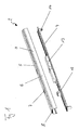
- eine perspektivische Ansicht einer Leuchte mit voneinander gelöster Tragschiene und Geräteträger als Element eines Lichtbandes; und
- Fig. 2
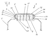
- eine Schnittansicht einer Tragschiene mit eingesetztem Stromführungs-profil.
- Fig. 1
- a perspective view of a lamp with separate support rail and equipment carrier as an element of a light band; and
- Fig. 2
- a sectional view of a mounting rail with inserted current-carrying profile.
In
Die Tragschiene 3 weist ein etwa U-förmiges Profil auf, welches aus einem Grundprofil 5 mit seitlichem Stegprofil 6 aufgebaut ist. Im Grundprofil 5 sind zusätzliche Aussparungen 7 vorgesehen, um Kabel der Stromversorgung einzuführen. In die Tragschiene 3 ist ein Stromführungsprofil 8 mittels des erfindungsgemäßen Befestigungssystemes eingebracht.The
Unterhalb der Tragschiene 3 ist ein Geräteträger 4 dargestellt. Dieser Geräteträger 4 weist an seiner der Tragschiene 3 zugewandten Seite eine Kontakteinrichtung 12 sowie beispielhaft eine oder mehrere elektronische Baugruppen 13 auf. Zur Montage dieser Leuchte 2 eines Lichtbandes wird der Geräteträger 4 von unten in die Tragschiene 3 eingeschoben und befestigt. Diese Befestigung kann beispielsweise durch eine form- oder kraftschlüssige Klemmung mit entsprechender Sicherung durchgeführt werden.Below the
Beim Einsetzen des Geräteträgers 4 in die Tragschiene 3 kontaktiert die Kontakteinrichtung 12 das Stromführungsprofil 8. Hierdurch ist es möglich, über die Kontakteinrichtung 12 Steuersignale und/oder Energie von dem Stromführungsprofil 8 abzunehmen.When inserting the device carrier 4 into the mounting
Am Geräteträger 4 sind zusätzlich noch zwei Anschlüsse 14 für Leuchtmittel vorgesehen. In der hier dargestellten Form kann beispielsweise eine Leuchtstofflampe eingesetzt werden. Diese Leuchtstofflampe wird mit über die Kontakteinrichtung 12 abgenommenen Strom versorgt. Im Bereich 13 können weitere elektrische oder elektronische Einrichtungen vorgesehen sein, die zum Beispiel zum Betrieb des Leuchtmittels benötigt werden.On the equipment carrier 4 two
Im Folgenden wird anhand von
Die Tragschiene 3 ist hierbei aus einem Grundprofil 5 und einem Stegprofil 6 aufgebaut. Das Stegprofil 6 weist einen ersten Steg 37 und einen zweiten Steg 38 auf.The
In dieser Darstellung ist das Stromführungsprofil 8 in die Tragschiene 3 eingebracht. Das Stromführungsprofil 8 weist eine Anlagefläche 33 und davon abstehenden Leiterstegen 45 auf. In diesen Leiterstegen 45 befinden sich jeweils ein oder zwei elektrische Leiter 44. Insgesamt sind hierbei elf Leiter 44 vorgesehen. Von diesen elf Leitern 44 sind drei Leiter 44 für die Phasen, einer als Nullleiter und einer als Schutzleiter vorgesehen. Des Weiteren sind sechs Leiter 44 mit geringerem Durchmesser in den Leiterstegen 45 vorgesehen. Hierbei können zwei als Steuerleitung und die restlichen vier als zwei separate Notstromkreisläufe verwendet werden.In this illustration, the current-carrying
An den seitlichen Enden der Anlagefläche 33 befinden sich jeweils Vorsprünge 34 als Verlängerung der Anlagefläche 33. Diese Vorsprünge 34 werden als Klemmeinrichtungen 23 für eine formschlüssige Befestigung des Stromführungsprofils 8 in der Tragschiene 3 verwendet.At the lateral ends of the
Die zwei seitlichen Stege 37 und 38 des Stegprofils 6 weisen im Bereich nahe der Auflagefläche 32 des Grundprofils 5 eine S-förmige bzw. Z-ähnliche Form auf. Hierdurch wird eine Einbauchung 26 und eine Ausbauchung 27 auf beiden Seiten des Stegprofils 6 gebildet. Die Einbauchung 26 bildet einen Ablenkkörper 22, und die Ausbauchung 27 eine Klemmeinrichtung 23.The two
Die lichte Weite zwischen den beiden Einbauchungen 26 auf beiden Seiten 37, 38 des Stegprofils 6 ist hierbei nur geringfügig größer als die Breite der Anlagefläche 33 des Stromführungsprofils 6. Hierdurch wird eine erste Engstelle 41 ausgebildet. An einer zweiten Stelle 42, welche sich ungefähr an der Ausbauchung 27 befindet, ist die lichte Weite zwischen beiden Stegen 37, 38 des Stegprofils 6 wiederum größer ausgebildet als die Breite der Anlagefläche 33.The clear width between the two
Durch eine derartige Ausgestaltung der Stegprofile 6 der Tragschiene 3 und des Stromführungsprofils 8 ist es möglich, das Stromführungsprofil 8 werkzeuglos in der Tragschiene 3 zu befestigen.Such a configuration of the
Im Folgenden wird die Befestigung des Stromführungsprofils 8 in der Tragschiene 3 beschrieben. Das Stromführungsprofil 8 wird von unten in die Tragschiene 3 eingeschoben, bis die Anlagefläche 33 auf der Auflagefläche 32 des Grundprofils 5 aufliegt.In the following, the attachment of the current-carrying
Während des Einschiebens werden die Vorsprünge 34 des Stromführungsprofils 8 an der ersten Stelle 41 durch die Einbauchung 26 abgelenkt und an die Seiten des Stromführungsprofils 8 bzw. dessen äußere Leiterstege 45 gedrückt. Wird das Stromführungsprofil 8 weiter in die Tragschiene eingeschoben, bis die Anlagefläche 33 auf der Auflagefläche 32 aufliegt, so erreichen die Vorsprünge 34 die zweite Stelle 42. Die Vorsprünge 34 sind derart ausgebildet, dass sie elastische bzw. federnde Eigenschaften haben und wieder in ihre Ausgangsposition, beabstandet von den Leiterstegen 45, zurückkehren. Durch die Ausbauchung 27 ist ihnen dieses Zurückkehren möglich, sobald die Anlagefläche 33 auf der Auflagefläche 32 aufliegt. Dadurch dass die Vorsprünge 34 wieder in ihre ursprüngliche Position zurückgekehrt sind, verklemmen sie sich in den Ausbauchungen 27, so dass das Stromführungsprofil 8 nicht mehr zurückgezogen werden kann.During insertion, the projections 34 of the current-carrying
Somit wird das Stromführungsprofil 8 durch einfaches Einschieben in die Tragschiene 3 in dieser werkzeuglos befestigt. Die Befestigung kann auch als Einklipsen bezeichnet werden.Thus, the current-carrying
In dieser Figur sind die elektrischen Leitungen 44 mit einem runden Querschnitt dargestellt. Um den Halt dieser elektrischen Leitungen 44 in den Leiterstegen 45 zu verbessern, können die Leitungen 44 auch einen anderen Querschnitt, beispielsweise dreiecksähnlich, knochenähnlich, H- oder T-förmig aufweisen.In this figure, the
Sind verschiedene Ausführungen des Stromführungsprofils 8 mit einer unterschiedlichen Anzahl und/oder Verteilung von elektrischen Leitungen 44 vorgesehen, so kann das Stromführungsprofil 8 oder zumindest Teile davon abhängig von der Anzahl und/oder Verteilung der elektrischen Leitungen 44 farblich gekennzeichnet sein.If different embodiments of the current-carrying
Mit dem erfindungsgemäßen Stromführungssystem für Lichtbänder oder Leuchten ist es somit möglich, die Energieversorgungsleitungen einfach und werkzeuglos anzubringen. Außerdem wird durch das erfindungsgemäße System die Ausfallwahrscheinlichkeit verringert.With the power supply system according to the invention for light bands or lights, it is thus possible to install the power supply lines easily and without tools. In addition, the failure probability is reduced by the system according to the invention.
Claims (14)
mit einer Tragschiene (3), welche mindestens ein Grundprofil (5) mit seitlichem Stegprofil (6) aufweist und
mit einem Stromführungsprofil (8),
wobei
an dem seitlichen Stegprofil (6) und an den dem Stegprofil (6) zugewandten Seiten des Stromführungsprofils (8) zusammenwirkende Bereiche (22, 23, 24, 26, 27, 34) mindestens einer Befestigungseinrichtung ausgebildet sind, und
die mindestens eine Befestigungseinrichtung zur werkzeuglosen Befestigung des Stromführungsprofils (8) an der Tragschiene (3) vorgesehen ist.Power supply system (1) for continuous lighting or luminaires (2)
with a mounting rail (3), which has at least one base profile (5) with lateral web profile (6) and
with a current-carrying profile (8),
in which
on the lateral web profile (6) and on the said web profile (6) facing sides of the current-carrying profile (8) cooperating regions (22, 23, 24, 26, 27, 34) are formed at least one fastening device, and
the at least one fastening device for tool-free attachment of the current-carrying profile (8) to the support rail (3) is provided.
dadurch gekennzeichnet,
dass sich die zusammenwirkenden Bereiche (22, 23, 24, 26, 27, 34), der mindestens einen Befestigungseinrichtung im Wesentlichen über die gesamte Länge des Grundprofils (5) und des Stromführungsprofils (8) erstrecken.Power supply system according to claim 1,
characterized,
in that the cooperating regions (22, 23, 24, 26, 27, 34) of the at least one fastening device extend over substantially the entire length of the base profile (5) and of the current-carrying profile (8).
dadurch gekennzeichnet,
dass die zusammenwirkenden Bereiche der mindestens einen Befestigungseinrichtung Ablenkkörper (22), Klemmeinrichtungen (23) und Klemmkörper (24) aufweisen.Power supply system according to claim 1 or 2,
characterized,
in that the cooperating regions of the at least one fastening device have deflection bodies (22), clamping devices (23) and clamping bodies (24).
dadurch gekennzeichnet,
dass das seitliche Stegprofil (6) in der Nähe des Grundprofils (5) eine Ein- und Ausbauchung (27, 28), insbesondere etwa Z- oder S-förmig, aufweist.Power supply system according to one of claims 1 to 3,
characterized,
that the lateral web profile (6) in the vicinity of the base profile (5) has a bulge and bulge (27, 28), in particular approximately Z- or S-shaped.
dadurch gekennzeichnet,
dass das Grundprofil (5) der Tragschiene (3) eine Auflagefläche (32) aufweist, dass das Stromführungsprofil (8) eine Anlagefläche (33) aufweist und dass die Breite der Anlagefläche (33) des Stromführungsprofils (2) im Wesentlicher kleiner oder gleich der Breite der Auflagefläche (32) des Grundprofils (5) ist.Power supply system according to one of claims 1 to 4,
characterized,
in that the base profile (5) of the mounting rail (3) has a support surface (32), that the current-carrying profile (8) has a contact surface (33) and that the width of the contact surface (33) of the current-carrying profile (2) is substantially less than or equal to Width of the bearing surface (32) of the base profile (5).
dadurch gekennzeichnet,
dass das Stromführungsprofil (8) Vorsprünge (34) aufweist, welche über die Anlagefläche (33) hinausragen und
dass die Vorsprünge (34) elastisch oder federnd am Stromführungsprofil (8) vorgesehen sind.Power management system according to one of claims 1 to 5,
characterized,
that the current-carrying profile (8) has projections (34) which project beyond the contact surface (33) and
in that the projections (34) are provided elastically or resiliently on the current-carrying profile (8).
dadurch gekennzeichnet,
dass mindestens ein Bereich (23, 34) der zusammenwirkenden Bereiche der mindestens einen Befestigungseinrichtung als Verlängerung der Anlagefläche (33) des Stromführungsprofils (8) ausgebildet ist.Power supply system according to one of claims 1 to 6,
characterized,
in that at least one region (23, 34) of the cooperating regions of the at least one fastening device is formed as an extension of the contact surface (33) of the current-carrying profile (8).
dadurch gekennzeichnet,
dass das seitliche Stegprofil (6) zwei Stege (37, 38) aufweist,
dass die lichte Weite zwischen den zwei Stegen (37, 38) des Stegprofils (6) an mindestens einer ersten Stelle (41) im Wesentlichen der Breite der Anlagefläche (33) des Stromführungsprofils (8) entspricht,
dass die lichte Weite an einer zweiten Stelle (42) zwischen den beiden Stegen (37, 38) des Stegprofils (6) größer als die Breite der Anlagefläche (33) des Stromführungsprofils (8) ausgebildet ist und
dass die zweite Stelle (42) näher am Grundprofil (5) der Tragschiene (3) als die erste Stelle (41) vorgesehen ist.Power supply system according to one of claims 1 to 7,
characterized,
that the lateral web profile (6) has two webs (37, 38),
that the clear width between the two webs (37, 38) of the web profile (6) on at least a first location (41) substantially to the width of the contact surface (33) corresponds to the current carrying profile (8),
that the clear width at a second point (42) between the two webs (37, 38) of the web profile (6) is greater than the width of the contact surface (33) of the current-carrying profile (8) is formed and
in that the second location (42) is provided closer to the base profile (5) of the mounting rail (3) than the first location (41).
dadurch gekennzeichnet,
dass die zusammenwirkenden Bereiche (22, 23, 24, 26, 27, 34) der mindestens einen Befestigungseinrichtung eine form- und/oder kraftschlüssige Verbindung ausbilden.Power supply system according to one of claims 1 to 8,
characterized,
that the cooperating regions (22, 23, 24, 26, 27, 34) of the at least form a fastening device a positive and / or non-positive connection.
dadurch gekennzeichnet,
dass das Stromführungsprofil (8) flexibel, insbesondere aufrollbar, ausgebildet ist.Power supply system according to one of claims 1 to 9,
characterized,
that the current-carrying profile (8) is flexible, in particular rollable, is formed.
dadurch gekennzeichnet,
dass das Stromführungsprofil (8) mehrere elektrische Leiter (46) aufweist.Power supply system according to one of claims 1 to 10,
characterized,
in that the current-carrying profile (8) has a plurality of electrical conductors (46).
dadurch gekennzeichnet,
dass das Stromführungsprofil (8) bandartig aus einem elektrisch isolierenden Kunststoffmaterial hergestellt, insbesondere extrudiert, ist.Power supply system according to one of claims 1 to 11,
characterized,
that the current-carrying profile (8) is made of a strip of an electrically insulating plastic material, in particular extruded, is.
Applications Claiming Priority (1)
| Application Number | Priority Date | Filing Date | Title |
|---|---|---|---|
| DE200820001962 DE202008001962U1 (en) | 2008-02-13 | 2008-02-13 | Power supply system for lighting strips or luminaires |
Publications (1)
| Publication Number | Publication Date |
|---|---|
| EP2091112A1 true EP2091112A1 (en) | 2009-08-19 |
Family
ID=39311728
Family Applications (1)
| Application Number | Title | Priority Date | Filing Date |
|---|---|---|---|
| EP08008128A Withdrawn EP2091112A1 (en) | 2008-02-13 | 2008-04-28 | Electricity supply system for light strips or lights |
Country Status (2)
| Country | Link |
|---|---|
| EP (1) | EP2091112A1 (en) |
| DE (1) | DE202008001962U1 (en) |
Citations (3)
| Publication number | Priority date | Publication date | Assignee | Title |
|---|---|---|---|---|
| DE4042395A1 (en) * | 1990-08-04 | 1992-02-20 | Halloform Gmbh & Co Kg | Electrical current rail adaptor - is secured within current rail housing by opposing releasable locking clips |
| DE4312888A1 (en) * | 1993-04-20 | 1994-10-27 | Siemens Ag | Plug connection for a striplight arrangement |
| DE29817256U1 (en) * | 1998-09-25 | 1998-12-17 | Thorn Licht Gmbh | DIN rail light |
-
2008
- 2008-02-13 DE DE200820001962 patent/DE202008001962U1/en not_active Expired - Lifetime
- 2008-04-28 EP EP08008128A patent/EP2091112A1/en not_active Withdrawn
Patent Citations (3)
| Publication number | Priority date | Publication date | Assignee | Title |
|---|---|---|---|---|
| DE4042395A1 (en) * | 1990-08-04 | 1992-02-20 | Halloform Gmbh & Co Kg | Electrical current rail adaptor - is secured within current rail housing by opposing releasable locking clips |
| DE4312888A1 (en) * | 1993-04-20 | 1994-10-27 | Siemens Ag | Plug connection for a striplight arrangement |
| DE29817256U1 (en) * | 1998-09-25 | 1998-12-17 | Thorn Licht Gmbh | DIN rail light |
Also Published As
| Publication number | Publication date |
|---|---|
| DE202008001962U1 (en) | 2008-04-17 |
Similar Documents
| Publication | Publication Date | Title |
|---|---|---|
| EP2915215B1 (en) | Series module arrangement with an energy bus system | |
| EP1016821B1 (en) | Strip lighting system comprising a support rail to be mounted to a wall or to a ceiling | |
| EP2091111B1 (en) | Contact system for light strips or lights | |
| EP4042525B1 (en) | Busbar for lamps or electrical units | |
| WO2019081592A1 (en) | Cable retainer, busbar element, busbar system, mechanical connecting element for a busbar system, method for producing a busbar element, and method for producing a busbar system | |
| EP2091113B1 (en) | Connection system for light strips or lights | |
| EP2573883B1 (en) | End cap for current-carrying profiles of a power distributor assembly. | |
| EP1475565B1 (en) | Lamp assembly | |
| EP3701606B1 (en) | Line holder system, busbar element, method for producing a busbar element and method for producing a busbar system | |
| EP2827051B1 (en) | Lamp | |
| EP3856568B1 (en) | Extensible connector for a contact line, and contact line | |
| EP0911914B1 (en) | Electrical coupling system | |
| AT516443B1 (en) | Luminaire with contacting module | |
| EP3975349B1 (en) | Elongated support rail and support rail system | |
| DE3817133C2 (en) | ||
| EP2091112A1 (en) | Electricity supply system for light strips or lights | |
| EP3540304B1 (en) | System for realizing a light strip | |
| EP3232513B1 (en) | System for balancing electrical potential gradients and potential equalisation terminal therefor | |
| DE102009006537A1 (en) | Bus bar for supplying current to electrical consumer i.e. lighting unit, has base body comprising groove that extends in longitudinal direction of body, and covering element glued with body for covering sections of groove | |
| DE202018105607U1 (en) | Luminaire connection and luminaire band | |
| EP4122058B1 (en) | Light strip having connected illuminating elements | |
| DE2538199A1 (en) | T-Junction screw terminal for insulated through wire - has open slot and pointed screw for through wire | |
| EP1626466B1 (en) | Bus bar assembly for electrically conductive connection of in-phase pole in an electric distribution installation | |
| DE102018131996A1 (en) | Variable positioning using a track | |
| DE102022126024A1 (en) | Light strip with disassembly-optimized components |
Legal Events
| Date | Code | Title | Description |
|---|---|---|---|
| PUAI | Public reference made under article 153(3) epc to a published international application that has entered the european phase |
Free format text: ORIGINAL CODE: 0009012 |
|
| AK | Designated contracting states |
Kind code of ref document: A1 Designated state(s): AT BE BG CH CY CZ DE DK EE ES FI FR GB GR HR HU IE IS IT LI LT LU LV MC MT NL NO PL PT RO SE SI SK TR |
|
| AX | Request for extension of the european patent |
Extension state: AL BA MK RS |
|
| AKX | Designation fees paid | ||
| STAA | Information on the status of an ep patent application or granted ep patent |
Free format text: STATUS: THE APPLICATION IS DEEMED TO BE WITHDRAWN |
|
| 18D | Application deemed to be withdrawn |
Effective date: 20100220 |
|
| REG | Reference to a national code |
Ref country code: DE Ref legal event code: 8566 |