EP2090868A2 - Improved start time of gyro assembly - Google Patents
Improved start time of gyro assembly Download PDFInfo
- Publication number
- EP2090868A2 EP2090868A2 EP09152096A EP09152096A EP2090868A2 EP 2090868 A2 EP2090868 A2 EP 2090868A2 EP 09152096 A EP09152096 A EP 09152096A EP 09152096 A EP09152096 A EP 09152096A EP 2090868 A2 EP2090868 A2 EP 2090868A2
- Authority
- EP
- European Patent Office
- Prior art keywords
- gyroscope
- gain setting
- value
- setting
- loop gain
- Prior art date
- Legal status (The legal status is an assumption and is not a legal conclusion. Google has not performed a legal analysis and makes no representation as to the accuracy of the status listed.)
- Withdrawn
Links
- 238000004891 communication Methods 0.000 claims abstract description 4
- 238000005259 measurement Methods 0.000 claims abstract description 4
- 238000000034 method Methods 0.000 claims description 10
- 230000010355 oscillation Effects 0.000 description 7
- 238000012545 processing Methods 0.000 description 4
- 238000013459 approach Methods 0.000 description 2
- 238000013461 design Methods 0.000 description 2
- 230000008094 contradictory effect Effects 0.000 description 1
- 230000000694 effects Effects 0.000 description 1
- 238000001914 filtration Methods 0.000 description 1
- 238000004519 manufacturing process Methods 0.000 description 1
- 230000003534 oscillatory effect Effects 0.000 description 1
- 230000000737 periodic effect Effects 0.000 description 1
- 238000005070 sampling Methods 0.000 description 1
Images


Classifications
-
- G—PHYSICS
- G01—MEASURING; TESTING
- G01C—MEASURING DISTANCES, LEVELS OR BEARINGS; SURVEYING; NAVIGATION; GYROSCOPIC INSTRUMENTS; PHOTOGRAMMETRY OR VIDEOGRAMMETRY
- G01C21/00—Navigation; Navigational instruments not provided for in groups G01C1/00 - G01C19/00
- G01C21/10—Navigation; Navigational instruments not provided for in groups G01C1/00 - G01C19/00 by using measurements of speed or acceleration
- G01C21/12—Navigation; Navigational instruments not provided for in groups G01C1/00 - G01C19/00 by using measurements of speed or acceleration executed aboard the object being navigated; Dead reckoning
- G01C21/16—Navigation; Navigational instruments not provided for in groups G01C1/00 - G01C19/00 by using measurements of speed or acceleration executed aboard the object being navigated; Dead reckoning by integrating acceleration or speed, i.e. inertial navigation
- G01C21/166—Mechanical, construction or arrangement details of inertial navigation systems
Definitions
- an inertial measurement unit includes an assembly including a plurality of gyroscopes. Each gyroscope has an associated motor bias loop gain setting.
- the IMU further includes an electronic device in signal communication with the gyroscopes. The device is configured to set the loop gain setting of a first gyroscope of the plurality to a first value to commence a startup time period of operation of the first gyroscope. The device is further configured to set the loop gain setting of the first gyroscope to a second value to commence a normal time period of operation of the first gyroscope.
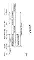
- FIG. 2 shows a timeline illustrating an embodiment of the present invention
- FIG. 3 shows a process according to an embodiment of the invention.
- devices such as, for example, the Honeywell® HG1930 Inertial Measurement Unit (IMU) 100, contain a 3-axis MEMS gyro assembly 110.
- Each channel (axis) of the gyro assembly contains one sensor and one analog ASIC (not shown).
- all three channels share one digital ASIC and/or other electronic device, such as a microprocessor 130.
- the ASICs control the gyro operation and provide the ability to configure individual control loop gains, described in further detail below, and other aspects of the gyro's operation.
- the gyro sensor operates using the Coriolis effect, and may oscillate at an approximate design frequency of 10 kHz to 15 kHz.
- the natural oscillation frequency varies from sensor to sensor due to manufacturing variability.
- a Phase Lock Loop (PLL) circuit controls the gyro proof mass oscillation.
- the proof mass and associated oscillation drive mechanism is also referred to as the gyro "motor”.
- PLL Phase Lock Loop
- the motor drive circuit (not shown) in the analog ASIC applies broadband white noise to the sensor motor in an attempt to find the sensor's natural frequency.
- the PLL control circuit waits a fixed period of time to ensure the motor control circuit has stabilized at the sensor's natural frequency. After that fixed period of time (in an embodiment, 400 ms), the PLOCK condition is declared. The amount of time it takes the circuit to find the frequency and attain the PLOCK condition is a driver of a gyro channel's start time.
- a third control loop searches for the amount of quadrature (sometimes called "motor bias") specific to that sensor.
- Quadrature is motion of the proof mass 90 degrees out of phase with the driven oscillatory motion.
- the motor bias control circuit of the Honeywell HG1930 IMU has a long time constant, a result of the filtering mechanism used to improve stability of the control loop during steady state operation. Depending upon how the motor bias loop is configured, and the natural amount of quadrature for a given sensor, it can take the loop several hundred milliseconds up to several seconds to find the appropriate steady-state value. This is a driver in the start time of a gyro channel.
- the two main drivers in gyro start time are time to PLOCK and time for motor bias loop to converge.
- An embodiment of the invention described here addresses a start routine to address the sources of these main drivers.
- An embodiment of the invention requires the ability to change the gains of the individual loops during operation. Since the gains are set to values that are not consistent with desired normal operation, problems may occur during startup if the gains persist for too long.
- the rate signal gains are increased to maximum. This gives more signal in the motor bias loop and helps the loop converge faster.
- the maximum gains are suitable for short-duration start up but are not desirable for normal operating use in some applications.
- An embodiment of the invention takes advantage of higher rate signal gains.
- FIG. 2 An exemplary timeline 200 illustrating operation of an embodiment of the invention is indicated in FIG. 2 .
- these first two steps are easy to implement by including a fixed delay during the IMU power-on sequence.
- FIG. 3 illustrates a process 300 implementable in an assembly including a plurality of gyroscopes according to an embodiment of the invention.
- the process 300 is illustrated as a set of operations shown as discrete blocks.
- the process 300 may be implemented in any suitable hardware, software, firmware, or combination thereof.
- the process 300 may be implemented in computer-executable instructions that can be transferred from one computer, such as a server, to a second computer or other electronic device via a communications medium.
- the order in which the operations are described is not to be necessarily construed as a limitation.
- the rate AC gain is set or returned to its normal operating value.
Landscapes
- Engineering & Computer Science (AREA)
- Radar, Positioning & Navigation (AREA)
- Remote Sensing (AREA)
- Automation & Control Theory (AREA)
- Physics & Mathematics (AREA)
- General Physics & Mathematics (AREA)
- Gyroscopes (AREA)
Abstract
An inertial measurement unit (IMU) (100) includes an assembly (110) including a plurality of gyroscopes. Each gyroscope has an associated motor bias control loop gain setting. The IMU (100) further includes an electronic device (130) in signal communication with the gyroscopes. The device (130) is configured to set the loop gain setting of a first gyroscope of the plurality to a first value to commence a startup time period of operation of the first gyroscope. The device (130) is further configured to set the loop gain setting of the first gyroscope to a second value to commence a normal time period of operation of the first gyroscope.
Description
- The start time of MEMS tuning fork gyros is often limited by the gains of various control loops required for operation. The optimized settings for the control loops for quick start are often contradictory to the optimized settings for high performance steady state operation. Many programs require both fast start times and high performance steady state operation.
- In an embodiment of the invention, an inertial measurement unit (IMU) includes an assembly including a plurality of gyroscopes. Each gyroscope has an associated motor bias loop gain setting. The IMU further includes an electronic device in signal communication with the gyroscopes. The device is configured to set the loop gain setting of a first gyroscope of the plurality to a first value to commence a startup time period of operation of the first gyroscope. The device is further configured to set the loop gain setting of the first gyroscope to a second value to commence a normal time period of operation of the first gyroscope.
- Preferred and alternative embodiments of the present invention are described in detail below with reference to the following drawings.
-
FIG. 1 shows an IMU incorporating embodiments of the present invention; -
FIG. 2 shows a timeline illustrating an embodiment of the present invention; and -
FIG. 3 shows a process according to an embodiment of the invention. - Referring to
FIG. 1 , devices according to an embodiment, such as, for example, the Honeywell® HG1930 Inertial Measurement Unit (IMU) 100, contain a 3-axisMEMS gyro assembly 110. Each channel (axis) of the gyro assembly contains one sensor and one analog ASIC (not shown). In an embodiment, all three channels share one digital ASIC and/or other electronic device, such as amicroprocessor 130. In an embodiment, the ASICs control the gyro operation and provide the ability to configure individual control loop gains, described in further detail below, and other aspects of the gyro's operation. - The gyro sensor operates using the Coriolis effect, and may oscillate at an approximate design frequency of 10 kHz to 15 kHz. The natural oscillation frequency varies from sensor to sensor due to manufacturing variability. A Phase Lock Loop (PLL) circuit controls the gyro proof mass oscillation. The proof mass and associated oscillation drive mechanism is also referred to as the gyro "motor". When the PLL has acquired the actual frequency of a given sensor, that condition is usually called "PLOCK" (PLL locked).
- In an embodiment, there are two kinds of gyro sensors: in-plane Upper Sense Plate (USP) gyros that sense rotation in the plane of the proof mass motion; and Out-of-Plane Gyros (OPG) that sense rotation perpendicular to the plane of the proof mass motion.
- As described in the following, there may be three simultaneous operations that occur when the gyro is started.
- When power is applied to the gyro assembly, the motor drive circuit (not shown) in the analog ASIC applies broadband white noise to the sensor motor in an attempt to find the sensor's natural frequency. Once a frequency is initially found, the PLL control circuit (not shown) waits a fixed period of time to ensure the motor control circuit has stabilized at the sensor's natural frequency. After that fixed period of time (in an embodiment, 400 ms), the PLOCK condition is declared. The amount of time it takes the circuit to find the frequency and attain the PLOCK condition is a driver of a gyro channel's start time.
- Simultaneously, the motor drive circuit applies a high drive amplitude. The Automatic Gain Control (AGC) circuit (not shown) applies high energy to the proof mass until the proof mass oscillation approaches the desired amplitude. Once the proof mass approaches the desired amplitude (which, in an embodiment, occurs within two hundred milliseconds after PLOCK is attained), the AGC circuit reduces the applied energy such that the motor maintains the desired oscillation amplitude. The rotation rate signal (rate pick-off) increases in amplitude as the gyro sensor increases in oscillation amplitude.
- As the gyro is starting and the rate pick-off signal becomes greater, a third control loop (not shown) searches for the amount of quadrature (sometimes called "motor bias") specific to that sensor. Quadrature is motion of the proof mass 90 degrees out of phase with the driven oscillatory motion. The motor bias control circuit of the Honeywell HG1930 IMU, for example, has a long time constant, a result of the filtering mechanism used to improve stability of the control loop during steady state operation. Depending upon how the motor bias loop is configured, and the natural amount of quadrature for a given sensor, it can take the loop several hundred milliseconds up to several seconds to find the appropriate steady-state value. This is a driver in the start time of a gyro channel.
- As discussed above, the two main drivers in gyro start time are time to PLOCK and time for motor bias loop to converge. An embodiment of the invention described here addresses a start routine to address the sources of these main drivers.
- An embodiment of the invention requires the ability to change the gains of the individual loops during operation. Since the gains are set to values that are not consistent with desired normal operation, problems may occur during startup if the gains persist for too long.
- To address PLOCK, the motor position pick-off gains (the motor charge amp and motor AC gain) are set in a configuration to increase the detected pickoff. This gives more signal in the PLL detector circuit and helps the PLL acquire the frequency faster.
- To address the motor bias loop, the rate signal gains are increased to maximum. This gives more signal in the motor bias loop and helps the loop converge faster. The maximum gains are suitable for short-duration start up but are not desirable for normal operating use in some applications. An embodiment of the invention takes advantage of higher rate signal gains.
- An
exemplary timeline 200 illustrating operation of an embodiment of the invention is indicated inFIG. 2 . - An embodiment of the invention includes software implemented by
microprocessor 130, although the below-described process may be implemented in hardware, firmware, software, or a combination of the three. The implementation of an embodiment involves three sets of HPGD2 and/or HPG2 (analog) ASIC register configuration changes. At power-up, the initial ASIC parameters are set. For dynamic start, this means the motor charge amp gain, motor AC gain, and rate AC gain are configured to give high signal output - as much as 10 to 20 times more gain then is present during normal operation. Specific settings may depend upon the exact circuit design. In an embodiment, the gyro is allowed to operate with these settings for approximately 140 milliseconds (ms). - After that fixed duration, the motor charge amp gain and motor AC gain are returned to their normal values. Normal operating gains depend upon the required operational environments and depend upon the specific application. The rate AC gain is left high at this time. The 140 ms time is typically long enough to allow the PLL to find the frequency, but not so long that the motor has attained significant oscillation amplitude.
- In an embodiment, these first two steps are easy to implement by including a fixed delay during the IMU power-on sequence.
- In an embodiment, the software implementation performs processing at periodic intervals to process a new set of inertial sensor samples. A typical case uses a sampling rate of 1800 Hz. The software is considered to be "hard real-time", and therefore timing of operations within a given sample/processing frame is optionally advantageous.
- The dynamic start control may therefore be implemented using a set of state machines associated with the
microprocessor 130 to reduce the processing overhead in each processing frame. Each gyro channel may have its own state machine to track the initialization status of each channel and the ASIC registers that have been set. The interface from theIMU microprocessor 130 to the gyro ASICs may be serial in nature, permitting only one register access at a time. Therefore, the software implements at least one state machine to control access to respective gyro ASICs. -
FIG. 3 illustrates a process 300 implementable in an assembly including a plurality of gyroscopes according to an embodiment of the invention. The process 300 is illustrated as a set of operations shown as discrete blocks. The process 300 may be implemented in any suitable hardware, software, firmware, or combination thereof. As such the process 300 may be implemented in computer-executable instructions that can be transferred from one computer, such as a server, to a second computer or other electronic device via a communications medium. The order in which the operations are described is not to be necessarily construed as a limitation. - At a
block 310, the motor charge amp gain, motor AC gain, and rate AC gain of a first IMU gyroscope of the gyroscope assembly are set to provide high signal output. In an embodiment, the gyroscope is allowed to operate with these settings for approximately 140 milliseconds (ms). - At a
block 320, the motor charge amp gain and motor AC gain are set or returned to their normal operating values. The rate AC gain is left high at this time. - At a
block 330, the rate AC gain is set or returned to its normal operating value. - At a
block 340, the steps described with reference to blocks 310-330 are repeated for a second IMU gyroscope of the gyroscope assembly. - While a preferred embodiment of the invention has been illustrated and described, as noted above, many changes can be made without departing from the spirit and scope of the invention. Accordingly, the scope of the invention is not limited by the disclosure of the preferred embodiment. Instead, the invention should be determined entirely by reference to the claims that follow.
The embodiments of the invention in which an exclusive property or privilege is claimed are defined as follows:
Claims (10)
- An inertial measurement unit (IMU) (100) comprising:an assembly (110) including a plurality of gyroscopes, each said gyroscope having an associated motor bias loop gain setting; andan electronic device (130) in signal communication with the gyroscopes, the device (130) configured to set the loop gain setting of a first gyroscope of the plurality to a first value to commence a startup time period of operation of the first gyroscope, and set the loop gain setting of the first gyroscope to a second value to commence a normal time period of operation of the first gyroscope.
- The unit (100) of claim 1 wherein the second value is less than the first value.
- The unit (100) of claim 1 wherein:each said gyroscope has an associated motor charge amplitude gain setting and rate AC gain setting; andsetting the loop gain setting of the first gyroscope to the first value includes setting the motor charge amplitude gain setting and rate AC gain setting to respective high values.
- The unit (100) of claim 3 wherein setting the loop gain setting of the first gyroscope to the second value includes setting the motor charge amplitude gain setting to an associated first low value.
- The unit (100) of claim 4 wherein setting the loop gain setting of the first gyroscope to the second value includes setting the rate AC gain setting to an associated second low value.
- The unit (100) of claim 4 wherein the motor charge amplitude gain setting is set to the first low value before the rate AC gain setting is set to the second low value.
- The unit (100) of claim 1 wherein:each of the gyroscopes includes at least one ASIC; andthe electronic device (130) is further configured to set the loop gain setting of the first gyroscope to the first and second values by configuring the ASIC associated with the first gyroscope.
- The unit (100) of claim 7 wherein the electronic device (130) is further configured to configure the ASIC associated with the first gyroscope by implementing at least one state machine.
- A method implementable in an assembly (110) including a plurality of gyroscopes, each said gyroscope having an associated motor bias loop gain setting, the method comprising:setting the loop gain setting of a first gyroscope of the plurality to a first value to commence a startup time period of operation of the first gyroscope; andsetting the loop gain setting of the first gyroscope to a second value to commence a normal time period of operation of the first gyroscope.
- The method of claim 9 wherein the second value is less than the first value.
Applications Claiming Priority (1)
| Application Number | Priority Date | Filing Date | Title |
|---|---|---|---|
| US12/031,950 US20100077856A1 (en) | 2008-02-15 | 2008-02-15 | Start time of gyro assembly |
Publications (1)
| Publication Number | Publication Date |
|---|---|
| EP2090868A2 true EP2090868A2 (en) | 2009-08-19 |
Family
ID=40635811
Family Applications (1)
| Application Number | Title | Priority Date | Filing Date |
|---|---|---|---|
| EP09152096A Withdrawn EP2090868A2 (en) | 2008-02-15 | 2009-02-04 | Improved start time of gyro assembly |
Country Status (2)
| Country | Link |
|---|---|
| US (1) | US20100077856A1 (en) |
| EP (1) | EP2090868A2 (en) |
Cited By (2)
| Publication number | Priority date | Publication date | Assignee | Title |
|---|---|---|---|---|
| EP2533011A3 (en) * | 2011-06-10 | 2016-10-05 | Honeywell International Inc. | Gyroscope dynamic motor amplitude compensation for enhanced rate estimation during startup |
| US9562767B2 (en) | 2014-08-12 | 2017-02-07 | Honeywell International Inc. | Systems and methods for improving MEMS gyroscope start time |
Families Citing this family (2)
| Publication number | Priority date | Publication date | Assignee | Title |
|---|---|---|---|---|
| US9146109B2 (en) * | 2012-11-26 | 2015-09-29 | Stmicroelectronics S.R.L. | Microelectromechanical gyroscope with improved start-up phase, system including the microelectromechanical gyroscope, and method for speeding-up the start up phase |
| US9464899B2 (en) * | 2013-01-25 | 2016-10-11 | MCube Inc. | Method of reducing gyroscope oscillator start-up time and device therefor |
Family Cites Families (7)
| Publication number | Priority date | Publication date | Assignee | Title |
|---|---|---|---|---|
| JPH09505668A (en) * | 1993-11-29 | 1997-06-03 | ハネウエル・インコーポレーテッド | Modular laser gyro |
| JP3932661B2 (en) * | 1998-03-31 | 2007-06-20 | 松下電器産業株式会社 | Angular velocity sensor drive circuit |
| US6586898B2 (en) * | 2001-05-01 | 2003-07-01 | Magnon Engineering, Inc. | Systems and methods of electric motor control |
| DE602005018322D1 (en) * | 2004-02-04 | 2010-01-28 | Atlantic Inertial Systems Ltd | METHOD FOR REDUCING THE PRELOAD FAULT IN A CIRCUIT WITH A VIBRATING STRUCTURE |
| US7190237B2 (en) * | 2004-05-27 | 2007-03-13 | Continental Automotive, Inc. | Open-loop start-up method for a resonating device |
| JP2006349409A (en) * | 2005-06-14 | 2006-12-28 | Denso Corp | Sensor circuit of electrostatic drive / capacitance detection type gyro sensor |
| DE102005034702A1 (en) * | 2005-07-26 | 2007-02-01 | Robert Bosch Gmbh | Method and circuit arrangement for safe startup of a rotation rate sensor |
-
2008
- 2008-02-15 US US12/031,950 patent/US20100077856A1/en not_active Abandoned
-
2009
- 2009-02-04 EP EP09152096A patent/EP2090868A2/en not_active Withdrawn
Cited By (2)
| Publication number | Priority date | Publication date | Assignee | Title |
|---|---|---|---|---|
| EP2533011A3 (en) * | 2011-06-10 | 2016-10-05 | Honeywell International Inc. | Gyroscope dynamic motor amplitude compensation for enhanced rate estimation during startup |
| US9562767B2 (en) | 2014-08-12 | 2017-02-07 | Honeywell International Inc. | Systems and methods for improving MEMS gyroscope start time |
Also Published As
| Publication number | Publication date |
|---|---|
| US20100077856A1 (en) | 2010-04-01 |
Similar Documents
| Publication | Publication Date | Title |
|---|---|---|
| US10480944B2 (en) | Microelectromechanical gyroscope with compensation of quadrature signal components | |
| US20150308829A1 (en) | Microelectromechanical gyroscope with open loop reading device and control method | |
| JP6383546B2 (en) | System and method for reducing offset variability in multiple multifunction sensor devices | |
| CN102227608B (en) | Gyroscopic measurement method using vibrating gyroscope | |
| EP2090868A2 (en) | Improved start time of gyro assembly | |
| CN115388910A (en) | Hemispherical resonant gyro error self-excitation method and system | |
| CN108844531B (en) | Quick oscillation starting control method and device for high-Q-value micro-electromechanical gyroscope | |
| KR20190005196A (en) | Method and apparatus for demodulating gyroscope signal | |
| US20210108921A1 (en) | Readout circuit for a mems gyroscope and method for operating such a readout circuit | |
| US9829319B2 (en) | Microelectromechanical device having an oscillating mass and a forcing stage, and method of controlling a microelectromechanical device | |
| JP2013527920A (en) | Sensor | |
| KR102455246B1 (en) | Digital controlled vco for vibrating structure gyroscope | |
| CN113639734B (en) | Digital Feedthrough Cancellation System for MEMS Capacitive Gyroscope | |
| JP2001280974A (en) | Gps receiver with function of sampling dr sensor | |
| JP2008134244A (en) | High speed read logic for MEMS gyroscopes | |
| Gregory et al. | MEMS rate and rate-integrating gyroscope control with commercial software defined radio hardware | |
| JP5561237B2 (en) | Vibrator drive circuit | |
| CN102539810A (en) | Apparatus for driving multi-axial angular velocity sensor | |
| JP2009264974A (en) | Inertial force sensor and start-up control method thereof | |
| US20150020593A1 (en) | Apparatus for driving inertial sensor and controlling method of the same | |
| US4354393A (en) | Phase locked gyroscope wheel supply for synchronous hysteresis motor | |
| CN114593723A (en) | Quartz tuning fork gyroscope circuit and gyroscope | |
| CN116481563B (en) | A rate-integrating gyroscope measurement and control method and device based on virtual rotation of detection axis | |
| CN114234950B (en) | Sensor system, method for operating a sensor system | |
| US9823072B2 (en) | Drive signal control for resonating elements |
Legal Events
| Date | Code | Title | Description |
|---|---|---|---|
| PUAI | Public reference made under article 153(3) epc to a published international application that has entered the european phase |
Free format text: ORIGINAL CODE: 0009012 |
|
| 17P | Request for examination filed |
Effective date: 20090204 |
|
| AK | Designated contracting states |
Kind code of ref document: A2 Designated state(s): AT BE BG CH CY CZ DE DK EE ES FI FR GB GR HR HU IE IS IT LI LT LU LV MC MK MT NL NO PL PT RO SE SI SK TR |
|
| AX | Request for extension of the european patent |
Extension state: AL BA RS |
|
| STAA | Information on the status of an ep patent application or granted ep patent |
Free format text: STATUS: THE APPLICATION HAS BEEN WITHDRAWN |
|
| 18W | Application withdrawn |
Effective date: 20110809 |