EP2090221A1 - Ophthalmologic apparatus - Google Patents
Ophthalmologic apparatus Download PDFInfo
- Publication number
- EP2090221A1 EP2090221A1 EP09000879A EP09000879A EP2090221A1 EP 2090221 A1 EP2090221 A1 EP 2090221A1 EP 09000879 A EP09000879 A EP 09000879A EP 09000879 A EP09000879 A EP 09000879A EP 2090221 A1 EP2090221 A1 EP 2090221A1
- Authority
- EP
- European Patent Office
- Prior art keywords
- eye
- examination
- distance
- ophthalmologic apparatus
- refractive
- Prior art date
- Legal status (The legal status is an assumption and is not a legal conclusion. Google has not performed a legal analysis and makes no representation as to the accuracy of the status listed.)
- Withdrawn
Links
- 238000005259 measurement Methods 0.000 claims description 90
- 230000000717 retained effect Effects 0.000 claims description 5
- 210000003128 head Anatomy 0.000 description 63
- 230000003287 optical effect Effects 0.000 description 59
- 230000007246 mechanism Effects 0.000 description 34
- 238000000034 method Methods 0.000 description 27
- 230000008569 process Effects 0.000 description 19
- 210000004087 cornea Anatomy 0.000 description 17
- 210000001061 forehead Anatomy 0.000 description 12
- 238000003384 imaging method Methods 0.000 description 10
- 238000004364 calculation method Methods 0.000 description 7
- 238000005507 spraying Methods 0.000 description 7
- 238000001514 detection method Methods 0.000 description 6
- 239000005357 flat glass Substances 0.000 description 6
- 210000004220 fundus oculi Anatomy 0.000 description 6
- 230000004044 response Effects 0.000 description 6
- 238000005286 illumination Methods 0.000 description 5
- 230000014509 gene expression Effects 0.000 description 4
- 230000001179 pupillary effect Effects 0.000 description 4
- 238000007796 conventional method Methods 0.000 description 3
- 230000004907 flux Effects 0.000 description 3
- 201000009310 astigmatism Diseases 0.000 description 2
- 238000006073 displacement reaction Methods 0.000 description 2
- 210000000744 eyelid Anatomy 0.000 description 2
- 238000012014 optical coherence tomography Methods 0.000 description 2
- 230000000007 visual effect Effects 0.000 description 2
- 0 CCC(C1)C2*3[C@]1C(C)(C(C)*#CC)C(C*)C23 Chemical compound CCC(C1)C2*3[C@]1C(C)(C(C)*#CC)C(C*)C23 0.000 description 1
- 230000004456 color vision Effects 0.000 description 1
- 230000006835 compression Effects 0.000 description 1
- 238000007906 compression Methods 0.000 description 1
- 238000010586 diagram Methods 0.000 description 1
- 230000000694 effects Effects 0.000 description 1
- 210000000871 endothelium corneal Anatomy 0.000 description 1
- 238000005516 engineering process Methods 0.000 description 1
- 238000012986 modification Methods 0.000 description 1
- 230000004048 modification Effects 0.000 description 1
- 238000003825 pressing Methods 0.000 description 1
- 210000001747 pupil Anatomy 0.000 description 1
- 230000005855 radiation Effects 0.000 description 1
- 239000007921 spray Substances 0.000 description 1
- 238000012360 testing method Methods 0.000 description 1
- 230000004304 visual acuity Effects 0.000 description 1
Images



Classifications
-
- A—HUMAN NECESSITIES
- A61—MEDICAL OR VETERINARY SCIENCE; HYGIENE
- A61B—DIAGNOSIS; SURGERY; IDENTIFICATION
- A61B3/00—Apparatus for testing the eyes; Instruments for examining the eyes
- A61B3/18—Arrangement of plural eye-testing or -examining apparatus
-
- A—HUMAN NECESSITIES
- A61—MEDICAL OR VETERINARY SCIENCE; HYGIENE
- A61B—DIAGNOSIS; SURGERY; IDENTIFICATION
- A61B3/00—Apparatus for testing the eyes; Instruments for examining the eyes
- A61B3/10—Objective types, i.e. instruments for examining the eyes independent of the patients' perceptions or reactions
- A61B3/16—Objective types, i.e. instruments for examining the eyes independent of the patients' perceptions or reactions for measuring intraocular pressure, e.g. tonometers
- A61B3/165—Non-contacting tonometers
-
- A—HUMAN NECESSITIES
- A61—MEDICAL OR VETERINARY SCIENCE; HYGIENE
- A61B—DIAGNOSIS; SURGERY; IDENTIFICATION
- A61B3/00—Apparatus for testing the eyes; Instruments for examining the eyes
- A61B3/0075—Apparatus for testing the eyes; Instruments for examining the eyes provided with adjusting devices, e.g. operated by control lever
-
- A—HUMAN NECESSITIES
- A61—MEDICAL OR VETERINARY SCIENCE; HYGIENE
- A61B—DIAGNOSIS; SURGERY; IDENTIFICATION
- A61B3/00—Apparatus for testing the eyes; Instruments for examining the eyes
- A61B3/0083—Apparatus for testing the eyes; Instruments for examining the eyes provided with means for patient positioning
-
- A—HUMAN NECESSITIES
- A61—MEDICAL OR VETERINARY SCIENCE; HYGIENE
- A61B—DIAGNOSIS; SURGERY; IDENTIFICATION
- A61B3/00—Apparatus for testing the eyes; Instruments for examining the eyes
- A61B3/10—Objective types, i.e. instruments for examining the eyes independent of the patients' perceptions or reactions
- A61B3/16—Objective types, i.e. instruments for examining the eyes independent of the patients' perceptions or reactions for measuring intraocular pressure, e.g. tonometers
-
- A—HUMAN NECESSITIES
- A61—MEDICAL OR VETERINARY SCIENCE; HYGIENE
- A61B—DIAGNOSIS; SURGERY; IDENTIFICATION
- A61B3/00—Apparatus for testing the eyes; Instruments for examining the eyes
- A61B3/10—Objective types, i.e. instruments for examining the eyes independent of the patients' perceptions or reactions
- A61B3/103—Objective types, i.e. instruments for examining the eyes independent of the patients' perceptions or reactions for determining refraction, e.g. refractometers, skiascopes
Definitions
- the present invention relates to an ophthalmologic apparatus that executes a plurality of examinations on an eye.
- This ophthalmologic apparatus incorporates a first measuring part (an eye-refractive-power/corneal-shape measuring part) and a second measuring part (a tonometry part). These measuring parts are arranged next to each other in the vertical direction.
- a working distance in tonometry is generally shorter than a working distance in eye-refractive-power measurement and corneal-shape measurement.
- the former working distance is set to approximately 11 mm, and the latter working distance is set to approximately 35 mm.
- the ophthalmologic apparatus is configured to avoid contact with the subject by moving the tonometry part in a direction of the working distance (an anteroposterior direction with respect to the eye) when switching from the eye-refractive-power measurement, etc., to the tonometry.
- Japanese Unexamined Patent Application Publication No. 2001-187024 describes a tonometer having a function of detecting the proximity to the subject and moving a measuring head.
- a tonometer disclosed on the Internet (URL: http://www.topcon.co.jp/eyecare/pdf/ct_90a.pdf) as a non-contact type tonometer CT-90A by TOPCON Corporation in an online catalogue (retrieved on February 6, 2008) has a function of automatically stopping the movement of the apparatus when the apparatus is too close to the cornea, and a function of notifying (with a display or an alarm) that the apparatus is too close to the cornea.
- the measuring unit it is also possible to configure the measuring unit to move at a high speed in order to reduce a time for switching between the right and left eyes.
- the weight of the measuring unit, etc. is taken into consideration, the safety in the subject may be lowered by decrease of the accuracy of the operation of moving the measuring unit, and the subject may feel anxious or surprised due to the sound generated during the movement.
- the ophthalmologic apparatus described in JP-A 2007-282671 automatically moves the tonometry part toward the eye when shifting from the measurement of the eye refractive power, etc., to the measurement of the ocular tension (i.e., when moving the measuring head in the vertical direction). Consequently, the tonometry part is placed 24 mm (subtracting 11 mm from 35 mm) closer to the eye than the eye-refractive-power/corneal-shape measuring part.
- the measuring head Before executing the tonometry, it is required to align the tonometry part with the eye.
- the measuring head may be moved in the anteroposterior direction.
- the nozzle may hit the eye.
- the ophthalmologic apparatus of JP-A 2007-282671 can prevent contact with the eye when the measuring head is moved in the vertical direction, but cannot effectively prevent contact with the eye during the alignment.
- the present invention is to solve the aforementioned problems, and an object of the present invention is to provide an ophthalmologic apparatus by which it is possible to increase the safety in the eye by automatically setting the movable range of the measuring head.
- the ophthalmologic apparatus has a first examining part, a second examining part, a driver, a storage, a setting part, and a controller.
- the first examining part executes a first examination at a first working distance on an eye.
- the second examining part executes a second examination on the eye at a second working distance shorter than the first working distance.
- the driver moves the first examining part and the second examining part.
- the storage previously stores distance information including the first working distance and a distance between the second examining part and the eye in the second examination.
- the setting part acquires position information of the first examining part when the first examination is executed, and sets a movable range of the second examining part in a direction of the second working distance based on the position information and the distance information.
- the controller controls the driver to move the second examining part only within the movable range. Furthermore, the ophthalmologic apparatus executes the second examination after executing the first examination.
- the ophthalmologic apparatus of the present invention it is possible to set the movable range of the second examining part in the direction of the second working distance based on the position information of the first examining part when executing the first examination and based on the previously stored distance information, and it is possible to move the second examining part only within the movable range. Therefore, it is possible to increase the safety in the eye.
- Figs. 1 to 6 show a configuration example of the ophthalmologic apparatus according to the present embodiment.
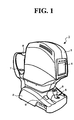
- the exterior of an ophthalmologic apparatus 1 is shown in Fig. 1 .
- the ophthalmologic apparatus 1 includes a base 2, a measuring head 3, a display 4, a control lever 5, a measurement switch 6, a jaw rest 7, a forehead rest 8, a jaw-rest moving switch 9, etc.
- a subject puts his/her jaw on the jaw rest 7 and faces the measuring head 3 with his/her forehead contact with the forehead rest 8.
- the jaw rest 7 and/or the forehead rest 8 is an example of a "retaining part" that retains the face of the subject.
- An operator operates the jaw-rest moving switch 9 to vertically move the jaw rest 7, thereby adjusting the position of the face of the subject. It is also possible to configure to move the forehead rest 8.
- the operator examines an eye while being positioned on a side where the display 4 and the control lever 5 are disposed. Further, in the case of executing eyelid opening on the subject, the operator may be positioned along the side face of the ophthalmologic apparatus 1.
- the vertical direction is the vertical direction.
- the anteroposterior direction is a direction that is orthogonal to the vertical direction and that connects the operator's side and the subject's side.
- the anteroposterior direction is a direction that is orthogonal to the vertical direction and that connects the side of the display 4 and the side of the jaw rest 7.
- a direction toward the subject's side is defined as the forward direction, and a direction opposite thereto is defined as the backward direction.
- the horizontal direction is a direction orthogonal to both the vertical direction and the anteroposterior direction.
- a direction from the right eye of the subject toward the left eye is defined as the leftward direction
- a direction opposite thereto is defined as the rightward direction.
- the base 2 houses a calculation control circuit, a storing device, a power supply circuit, etc.
- the measuring head 3 is configured to be movable in the vertical, anteroposterior and horizontal directions, i.e., movable three-dimensionally with respect to the base 2.
- the measuring head 3 is moved by a drive mechanism 10, which will be described later.
- the measuring head 3 is moved by the drive mechanism 10 at the time of alignment with the eye, switching of an examination method, switching of an examination object from one eye to the other eye, advance to a working distance in accordance with the examination method, and retreat to a safe distance at the time of the abovementioned switching.
- the display 4 displays an image such as an anterior segment image of an eye. Further, the display 4 displays various kinds of examination information such as patient information, examination conditions and examination results.
- the display 4 may be a touch panel display. In this case, various kinds of software keys are displayed on the display 4. The operator can cause the ophthalmologic apparatus 1 to execute a desired operation by pressing the software keys.
- the control lever 5 is operated, for example, to manually move the measuring head 3.
- the measurement switch 6 is operated, for example, to execute a measurement on the eye.
- Switches are also disposed around the display 4 (above and below in Fig. 1 ). These switches are used, for example, at the time of alignment with the eye and adjustment of the display 4.
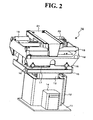
- the drive mechanism 10 shown in Fig. 2 is provided with a configuration for moving the measuring head 3 in the vertical, anteroposterior and horizontal directions.
- the drive mechanism 10 is housed in the base 2.
- a bottom plate 11 is fixedly installed in the base 2.
- a supporting part 12 is fixedly attached to the top face of the bottom plate 11.
- the supporting part 12 has a hollow part.
- a support column 13 is disposed in the hollow part.
- a vertical drive motor 14 is fixedly placed on the top face of the bottom plate 11.
- the vertical drive motor 14 includes an actuator such as a stepping motor (may be referred to as a pulse motor).
- a driving force generated by the vertical drive motor 14 is conveyed by a driving-force conveying mechanism, which is not illustrated, including gears, etc., to move the support column 13 in the vertical direction.
- a vertically moving stage 15 is fixedly attached to the upper end of the support column 13. The vertically moving stage 15 moves in the vertical direction together with the support column 13.
- Anteroposterior rails 16 are disposed near the horizontal end parts of the top face of the vertically moving stage 15, respectively.
- Each of the anteroposterior rails 16 is disposed so that a longitudinal direction thereof is along the anteroposterior direction.
- An anteroposterior moving stage 18 is mounted on the anteroposterior rails 16 so as to be movable in the anteroposterior direction.
- an anteroposterior drive motor 17 is provided on the top face of the vertically moving stage 15.
- the anteroposterior drive motor 17 includes an actuator such as a stepping motor.
- a driving force generated by the anteroposterior drive motor 17 is conveyed by a driving-force conveying mechanism, which is not illustrated, to move the anteroposterior moving stage 18 along the anteroposterior rails 16.
- the anteroposterior moving stage 18 is thereby moved in the anteroposterior direction with respect to the vertically moving stage 15.
- horizontal rails 19 are disposed. Each of the horizontal rails 19 is placed so that a longitudinal direction thereof is along the horizontal direction.
- a horizontal moving stage 21 is mounted on the horizontal rails 19 so as to be movable in the horizontal direction.
- a horizontal drive motor 20 is disposed on the top face of the anteroposterior moving stage 18.
- the horizontal drive motor 20 includes an actuator such as a stepping motor.
- a driving force generated by the horizontal drive motor 20 is conveyed by a driving-force conveying mechanism, which is not illustrated, to move the horizontal moving stage 21 along the horizontal rails 19.
- the horizontal moving stage 21 is thereby moved in the horizontal direction with respect to the anteroposterior moving stage 18.
- the measuring head 3 On the horizontal moving stage 21, the measuring head 3 is mounted. According to the drive mechanism 10, it is possible to separately move the measuring head 3 in the vertical direction, the anteroposterior direction and the horizontal direction.
- the measuring head 3 is provided with a plurality of examining parts that execute different ophthalmologic examinations on the eye.
- ophthalmologic examinations an eye-refractive-power examination, and an ocular-tension examination are employed particularly.
- Ophthalmologic examinations that can be executed by the ophthalmologic apparatus according to the present invention are not limited to the aforementioned ones, and may include any examination (measurement or photography) as exemplified below: visual acuity test, cornea-curvature examination, color-vision examination, visual-field examination, anterior segment, corneal endothelium photography, fundus oculi photography, OCT (Optical Coherence Tomography) examination, SLO (Scanning Laser Ophthalmoscope) examination, ultrasonic examination, radiation examination, and the like.
- the number of the ophthalmologic examinations that can be executed by the ophthalmologic apparatus related to the present invention may also be an arbitrary number of more than two.
- FIG. 3 The configuration of an optical system housed in the measuring head 3 is shown in Figs. 3 to 5 .
- An eye-refractive-power measuring system 100 shown in Fig. 3 is an optical system for measuring the eye refractive power (spherical degree, degree of astigmatism, astigmatic axis angle, etc.) and cornea shape of an eye E.
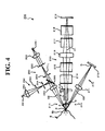
- a tonometry system 200 shown in Figs. 4 and 5 is an optical system for measuring the ocular tension of the eye E.
- the tonometry system 200 can also be used for measurement of the corneal thickness of the eye E.
- the measuring systems 100 and 200 each incorporates various kinds of optical elements, a drive mechanism, electric circuits, etc., in addition to the illustrated members (optical elements, etc.).
- the eye-refractive-power measuring system 100 and the tonometry system 200 are housed in, for example, cases (not illustrated), respectively.
- the eye-refractive-power measuring system 100 and the tonometry system 200 are placed next to each other in the vertical direction, for example. In the present embodiment, it is assumed that the eye-refractive-power measuring system 100 is placed above and the tonometry system 200 is placed below.
- the eye-refractive-power measuring system 100 has a configuration similar to that of a conventional eye-refractive-power measuring apparatus (refractometer) (refer to Japanese Patent No. 2937373 , for example). Furthermore, similarly to a conventional corneal-shape-measuring apparatus (keratometer), the eye-refractive-power measuring system 100 may have a configuration for measuring the intermediate value of the corneal radius of curvature (average corneal refractive power) or the corneal radius of curvature (corneal refractive power) of the steep meridian/flat meridian (refer to, for example, Japanese Unexamined Patent Application Publication No. 8-229007 ). The apparatus described in this document has functions of both the refractometer and the keratometer.
- the eye-refractive-power measuring system 100 includes an objective lens 105, a projecting system 110, an imaging system 120, a fixation-target projecting system 130, and an anterior-segment observing system 140.
- optical elements for measuring the corneal shape may be disposed.
- the projecting system 110 has an infrared LED (Light Emitting Diode) 112, a relay lens 113, a conic prism 114, a ring-shaped aperture diaphragm 115 and a relay lens 116, which are arranged along a reflected light axis 111 of an aperture mirror 117.
- the infrared LED 112 and the aperture mirror 117 are arranged so as to be conjugate with respect to the relay lenses 113 and 116.
- the aperture mirror 117 and a pupil Ep of the eye E are arranged so as to be conjugate with respect to the objective lens 105.
- the conic prism 114 and a fundus oculi Er are arranged so as to be conjugate with respect to the relay lens 116 and the objective lens 105.
- the imaging system 120 includes optical elements arranged on and along an optical axis 121.
- a relay lens 122 and a CCD image sensor 123 are disposed on the optical axis 121 behind the aperture mirror 117.
- the position A and a light-receiving face 124 of the CCD image sensor 123 are conjugate to each other with respect to the relay lens 122.
- the fixation-target projecting system 130 includes a fixation-target presenting part 132, a relay lens 133 and a dichroic mirror 134, which are arranged along an optical axis 131 branched out from a position on the optical axis 121 between the position A and the aperture mirror 117.
- the dichroic mirror 134 is obliquely disposed on the optical axis 121, and transmits an infrared light while reflecting a visible light.
- the fixation-target presenting part 132 is configured to be movable along the optical axis 131.
- the fixation-target presenting part 132 is placed at a conjugate position to the position A with respect to the relay lens 133.
- the anterior-segment observing system 140 includes a half mirror 142, a relay lens 143 and an imaging device 144, which are arranged along an optical axis 141 branched out from a position on the optical axis 121 between the objective lens 105 and the position A.
- the half mirror 142 is obliquely disposed on the optical axis 121.
- the imaging device 144 includes a solid-state imaging element such as a CCD image sensor and a CMOS image sensor, an imaging tube, or the like.
- a light-receiving face 145 of the imaging device 144 is arranged so as to be conjugate to an anterior segment Ef with respect to the objective lens 105 and the relay lens 143.
- the eye-refractive-power measuring system 100 may also have an alignment optical system for performing alignment of the measurement optical system with the eye E (position matching of the optical axis of the measurement optical system with the optical axis of the eye E).
- the measurement optical system is an optical system practically involved in the eye-refractive-power measurement, and is aligned with the optical axis of the objective lens 105 in this embodiment.
- As the alignment optical system it is possible to apply a configuration described in Japanese Unexamined Patent Application Publication No. 2004-222955 , for example. According to the configuration described in JP-A 2004-222955 , it is possible to automatically perform the alignment (auto-alignment function).
- the optical axis of the anterior-segment observing system 140 coincides with the optical axis of the measurement optical system (measurement optical axis), and the center position of the light-receiving face 145 coincides with the optical axis of the anterior-segment observing system 140.
- the anterior segment image of the eye E is acquired by the anterior-segment observing system 140, this anterior segment image is analyzed, and the optical axis position of the eye E is specified.
- the eye-refractive-power measuring system 100 (measuring head 3) is moved so as to negate the displacement, whereby it is possible to make the optical axis of the measurement optical system coincide with the optical axis of the eye E.
- a mode of measuring eye refractive power by the eye-refractive-power measuring system 100 will be described. It is assumed that the alignment of the eye-refractive-power measuring system 100 with the eye E is already completed. During the measurement, an image of the anterior segment Ef is acquired by the anterior-segment observing system 140. This image is displayed on the display 4, whereby it is possible to check whether the anterior segment Ef is placed in a proper position. Furthermore, a fixation target is projected to the fundus oculi Er by the fixation-target projecting system 130, whereby the eye is fixated in a foggy state.
- the infrared LED 112 is turned on in this state, and a ring image R1 is formed on the fundus oculi Er.
- a fundus reflected light of the ring image R1 is projected to the light-receiving face 124 of the CCD image sensor 123.
- the CCD image sensor 123 detects a projected image (ring image R2).
- the ophthalmologic apparatus 1 eye-refractive-power calculator 41 in Fig. 6 ) obtains the eye refractive power of the eye E by analyzing the shape of the ring image R2.
- the tonometry system 200 is provided with a configuration similar to that of a conventional noncontact type tonometer (e.g., Japanese Unexamined Patent Application Publication No. 2002-102170 ).
- the tonometry system 200 includes an anterior-segment observing system 210, an XY-alignment target projecting system 220, a fixation-target projecting system 230, an XY-alignment detecting system 240, a corneal-deformation detecting system 250, a slit projecting system 260, a light-receiving system 270, and a Z-alignment target projecting system 280.
- symbols X, Y and Z denote coordinate axes of a three-dimensional coordinate system.
- the X direction corresponds to the horizontal direction
- the Y direction corresponds to the vertical direction
- the Z direction corresponds to the anteroposterior direction.
- the anterior-segment observing system 210 includes a plurality of anterior-segment illumination light sources 211, an air-puff spraying nozzle 212, an anterior-segment window glass 213, a chamber window glass 214, a half mirror 215, an objective lens 216, half mirrors 217 and 218, and a CCD image sensor 219.
- the members 212 to 219 except the anterior-segment illumination light sources 211 are placed on an optical axis O1.
- the air-puff spraying nozzle 212 sprays air puff generated by a not-shown air compression mechanism toward the eye E.
- the plurality of the anterior-segment illumination light sources 211 are placed on the right and left positions of the eye E, and directly illuminate the anterior segment.
- the illumination lights emitted from the anterior-segment illumination light sources 211 are reflected at the anterior segment of the eye E, are passed through the inside and outside of the air-puff spraying nozzle 212, are passed through the anterior-segment window glass 213, the chamber window glass 214 and the half mirror 215, and are converged by the objective lens 216.
- the converged light flux is transmitted by the half mirrors 217 and 218, and projected to the light-receiving face of the CCD image sensor 219.
- the CCD image sensor 219 detects the projected image to capture an anterior segment image of the eye E.
- the XY-alignment target projecting system 220 includes an alignment light source 221, a condenser lens 222, an aperture diaphragm 223, a pinhole plate 224, a dichroic mirror 225, and a projection lens 226. These members 221 to 226 are placed on an optical axis branched out from the optical axis O1 by the half mirror 215.
- the dichroic mirror 225 reflects an infrared light and transmits a visible light.
- the alignment light source 221 emits an infrared light. This infrared light is passed through the aperture diaphragm 223 while being converged by the condenser lens 222, and is guided by the pinhole plate 224. The light flux passed through the pinhole plate 224 is reflected by the dichroic mirror 225 and collimated by the projection lens 226. This collimated light is reflected by the half mirror 215 and applied to the eye E along the optical axis O1. The emitted light is used as an XY-alignment target light for performing alignment in the XY direction.
- the fixation-target projecting system 230 includes a fixation-target light source 231, a pinhole plate 232, and a projection lens 226, which are placed on an optical axis branched out from the optical axis O1 by the half mirror 215.
- the visible light emitted by the fixation-target light source 231 is passed through the pinhole plate 232 and the dichroic mirror 225, and is collimated by the projection lens 226. This collimated light is reflected by the half mirror 215 and projected to the fundus oculi of the eye E along the optical axis O1. The reflected light is used as a fixation target.
- the XY-alignment detecting system 240 includes a half mirror 218 and an optical sensor 241.
- the optical sensor 241 is composed of a sensor capable of position detection, such as a PSD (Position Sensitive Detector).
- the XY-alignment target light applied to the eye E by the XY-alignment target projecting system 220 is reflected at the (surface of) the cornea Ec.
- the light reflected at the cornea is passed through the inside of the air-puff spraying nozzle 212, the anterior-segment window glass 213, the chamber window glass 214 and the half mirror 215, and is converged by the objective lens 216.
- the converged light transmitted by the half mirror 217 is split by the half mirror 218.
- Components reflected by the half mirror 218 form a bright-point image T1 on the receiving face of the optical sensor 241. Further, components transmitted by the half mirror 218 form a bright-point image T2 on the receiving face of the CCD image sensor 219.
- the ophthalmologic apparatus 1 calculates misalignment of the tonometry system 200 in the XY direction with respect to the cornea Ec, based on the result of detection of the bright-point image T1 by the optical sensor 241. Meanwhile, the result of detection of the bright-point image T2 by the CCD image sensor 219 is displayed on the display 4 together with the anterior segment image of the eye E. Consequently, it is possible to visually check the state of the alignment in the XY direction.
- the light flux reflected by the half mirror 217 is guided to the corneal-deformation detecting system 250, and detected by the optical sensor 252 through the pinhole plate 251.
- the optical sensor 252 is a sensor capable of detecting the amount of light such as a photodiode.
- the optical sensor 252 detects the amount of the light reflected by the cornea Ec applanated by the air puff from the air-puff spraying nozzle 212.
- the ophthalmologic apparatus 1 (an ocular-tension calculator 43) obtains the amount of deformation of the cornea Ec from the detection result, thereby obtaining the value of the ocular tension of the eye E.
- the slit projecting system 260 includes a slit light source 261, a condenser lens 262, a slit 263, a rectangular aperture diaphragm 264, a half mirror 285, and a projection lens 265. These members are placed on an optical axis 02.
- the slit 263 is placed so as to be conjugate to the rear face of the cornea Ec with respect to the projection lens 265.
- the slit light source 261 emits an infrared light. This infrared light is converged by the condenser lens 262 and guided into the slit 263.
- the infrared light passed through the slit 263 (a slit light L) is passed through the rectangular aperture diaphragm 264 and the half mirror 285, and is projected to the cornea Ec by the projection lens 265.
- the slit light L projected to the cornea Ec is reflected by the surface of the cornea and the rear face of the cornea.
- the light-receiving system 270 includes an imaging lens 271 and a line sensor 272. These members are placed on an optical axis 03.
- the optical axes 02 and 03 are disposed so that each of them forms an angle ⁇ with respect to the optical axis O1 in the opposite directions to each other in the horizontal direction.
- the corneal reflected light of the slit light L (surface reflection, rear-face reflection) is converged by the imaging lens 271 to form an image on the light-receiving face of the line sensor 272.
- the ophthalmologic apparatus 1 (the calculator 40) obtains the light amount distribution of the corneal reflected light based on an output signal from the line sensor 272, and performs alignment in the Z direction based on this light amount distribution. Furthermore, the ophthalmologic apparatus 1 (a corneal-thickness calculator) obtains the thickness of the cornea Ec based on two peak positions in the light amount distribution of the corneal reflection light.
- the Z-alignment target projecting system 280 includes an alignment light source 281, a condenser lens 282, an aperture diaphragm 283, a pinhole plate 284, a half mirror 285, and a projection lens 265.
- the pinhole plate 284 is placed in the focal position of the projection lens 265.
- the aperture diaphragm 283 is placed so as to be conjugate to a corneal apex P with respect to the projection lens 265.
- the infrared light emitted from the alignment light source 281 is converged by the condenser lens 282 to reach the aperture diaphragm 283.
- Part of the infrared light passed through the aperture diaphragm 283 is passed through the pinhole plate 284 to be reflected by the half mirror 285 and projected to the cornea Ec by the projection lens 265.
- the infrared light reflected at the (surface of the) cornea Ec is converged by the imaging lens 271 to form a bright-point image Q on the light-receiving face of the line sensor 272.
- the result of detection of this bright-point image Q is used for the alignment (rough adjustment) in the Z direction.
- FIG. 6 A configuration example of a control system of the ophthalmologic apparatus 1 is shown in Fig. 6 .
- the measuring head 3 has an eye-refractive-power measuring part 31 and a tonometry part 32.
- the eye-refractive-power measuring part 31 includes a configuration for measuring the eye refractive power of the eye E, such as the eye-refractive-power measuring system 100 shown in Fig. 3 .
- the eye-refractive-power measuring part 31 may include a configuration for measuring the corneal shape.
- the tonometry part 32 includes a configuration for measuring the ocular tension of the eye E, such as the tonometry system 200 shown in Figs. 4 and 5 .
- the tonometry part 32 may be configured to be also capable measuring the corneal thickness of the eye E. Measurement by the eye-refractive-power measuring part 31 is executed at a predetermined working distance Dr.
- the working distance Dr may be set to 35 mm, for example.
- the working distances for the eye refractive power measurement and the corneal shape measurement are equal to each other as in the conventional art. Further, measurement by the tonometry part 32 is executed at a predetermined working distance Dt.
- the working distance Dt may be set to 11 mm, for example.
- the working distance Dt is set to be shorter than the working distance Dr.
- the eye-refractive-power measuring part 31 is an example of the "first examining part” of the present invention.
- the tonometry part 32 is an example of the "second examining part” of the present invention.
- the working distance is set in advance for each examination in accordance with the type of the examination, the configuration of the measurement optical system, etc.
- the working distance can be set to a distance between the tip position of the measurement optical system and the eye E, or a distance between the eye E and the tip position (front face of the housing, etc.) of each examining part (the measuring parts 31 and 32).
- the definition of the working distance is consistently used for the plurality of examining parts in order to take a difference of working distances into consideration.
- the drive mechanism 10 has the vertical drive motor 14, the anteroposterior drive motor 17, and the horizontal drive motor 20, which are shown in Fig. 2 .
- the drive mechanism 10 is an example of the "driver" of the present invention.
- the calculator 40 calculates predetermined eye-characteristic information based on data obtained by the measuring head 3.
- the calculator 40 includes a microprocessor such as a CPU, a RAM, a ROM, a hard disk drive, etc.
- the calculator 40 has the refractive-power calculator 41, the corneal-shape calculator 42, and the ocular-tension calculator 43.
- the refractive-power calculator 41 calculates the eye refractive power (the spherical degree, degree of astigmatism, astigmatic axial angle, etc.) of the eye E based on data obtained by the eye-refractive-power measuring part 31.
- the corneal-shape calculator 42 calculates the corneal shape (average corneal refractive power, corneal refractive power, etc.) of the eye E based on data obtained by the eye-refractive-power measuring part 31.
- the ocular-tension calculator 43 calculates the value of ocular tension of the eye E based on data obtained by the tonometry part 32.
- the calculator 40 is also capable of calculating the corneal thickness of the eye E based on data obtained by the tonometry part 32. The aforementioned calculation processes are executed by the calculator 40 as in the conventional art.
- a user interface (UI) 50 includes a display device, an operation device, an input device, etc. Specifically, the user interface 50 includes the display 4, the control lever 5, the measurement switch 6, the jaw-rest moving switch 9, etc. In a case where a computer is connected to the ophthalmologic apparatus 1, the user interface 50 may include a display, a mouse, a keyboard, etc., of this computer.
- the controller 60 controls each part of the ophthalmologic apparatus 1.
- the controller 60 includes a microprocessor such as a CPU, a RAM, a ROM, a hard disk drive, etc.
- the controller 60 has a storage 61, a head-position acquiring part 62, a movable-range setting part 63, a drive controller 64, and a notification controller 65.
- the storage 61 stores various kinds of information on control of the ophthalmologic apparatus 1. Specifically, the storage 61 stores information on control of the drive mechanism 10, such as distance information 61 a.
- the storage 61 is an example of the "storage" of the present invention.
- the distance information 61a includes the working distance Dt for measurement by the tonometry part 32 and the working distance Dr for measurement by the eye-refractive-power measuring part 31.
- the distance information 61a includes a working distance for measurement by each of the plurality of examining parts. Each working distance is set in advance, and is previously stored in the storage 61 as the distance information 61a.
- the distance information 61a includes a safe distance Ds in an examination with the tonometry part 32.
- the safe distance Ds represents a distance at which (the air-puff spraying nozzle 212 of) the tonometry part 32 can be the closest to the eye E during the measurement of the ocular tension, i.e., the shortest distance from the eye E when the tonometry part 32 is moved in the anteroposterior direction in the measurement of ocular tension.
- the safe distance Ds is set to at least a distance at which the tonometry part 32 does not come in contact with the eye E.
- the safe distance Ds is set to 6 mm.
- the safe distance Ds is properly set beforehand.
- the head-position acquiring part 62 acquires the position information of the measuring head 3 at the current moment.
- the head-position acquiring part 62 acquires the position information of each of the measuring parts 31 and 32 at the current moment.
- the head-position acquiring part 62 is configured to acquire anteroposterior position information of the measuring head 3.
- each of the drive motors 14, 17 and 20 receives pulse signals from the drive controller 64, and moves the measuring head 3 by a distance in accordance with the number of the pulses. A moving distance corresponding to a single pulse is set in advance.
- the measuring head 3 is placed at a predetermined initial position at the time of, for example, start of an examination, it is possible to acquire three-dimensional position information of the measuring head 3 at the current moment by referring to the history of control signals transmitted by the drive controller 64 from a state where the measuring head 3 is placed in the initial position to the current moment.
- the initial position of the measuring head 3 can be set appropriately.
- the initial position can be manually set by the user.
- the head-position acquiring part 62 acquires position information of the eye-refractive-power measuring part 31 (the measuring head 3) specifically when measurement of the eye refractive power (measurement of the corneal shape) is executed.
- the head-position acquiring part 62 sends the acquired position information to the movable-range setting part 63.
- the movable-range setting part 63 receives position information from the head-position acquiring part 62, and reads out the distance information 61 a from the storage 61. Then, the movable-range setting part 63 sets a movable range of the tonometry part 32 (the measuring head 3) in a direction of the working distance Dt, based on this position information and the working distances Dr and Dt (or the difference ⁇ D between the working distances Dr and Dt). In this embodiment, the direction of the working distance Dt is the anteroposterior direction.
- the movable range represents a range within which movement of the tonometry part 32 (measuring head 3) in the anteroposterior direction is allowed.
- the movable range includes at least the boundary position toward the anterior direction (toward the eye E).
- the eye-refractive-power measuring part 31 measures the eye refractive power at a position away from the eye E by the working distance Dr. Further, the tonometry part 32 measures the ocular tension at a position away from the eye E by the working distance Dt. Symbol Ds represents the safe distance in ocular-tension measurement as mentioned above.
- the movable-range setting part 63 calculates a Z coordinate value Z3 corresponding to the safe distance Ds for tonometry based on a Z coordinate value Z1 of the eye-refractive-power measuring part 31 at the time of measurement of the eye refractive power and information registered in the distance information 61a.
- the Z coordinate value Z0 of the eye E is unknown until position information at the time of eye-refractive-power measurement is acquired by the head-position acquiring part 62.
- the Z coordinate values Z2 and Z3 are obtained in steps in the above calculation example, but it is also possible to employ another calculation method.
- the distance information 61 a includes the working distance Dt.
- the distance information 61a includes the working distance Dt, in order to determine the initial position in the anteroposterior direction of the measuring head 3 at the time of shift from eye-refractive-power measurement to tonometry.
- alignment with an actual eye is executed at the time of eye-refractive-power measurement to place the eye-refractive-power measuring part 31 so that a distance from the actual eye exactly becomes the working distance Dr (placement of the eye-refractive-power measuring part 31 at an examination position for the actual eye will be described in detail later in "Operation"), it is possible to acquire accurate position information based on the actual eye. Then, the Z coordinate values Z2 and Z3 are calculated based on the accurate position information of the eye-refractive-power measuring part 31.
- the shortest distance to the eye E i.e., the closest distance (the most advanced distance) to the eye E is set. Meanwhile, it is also possible to set the farthest distance from the eye E (the most retracted distance).
- the most retracted distance e.g., a few cm to as much as 10 cm.
- the most retracted distance may be set, by the drive mechanism 10, corresponding to the most retracted position of the tonometry part 32.
- Only the most advanced distance may be set without setting the most retracted distance.
- the movable-range setting part 63 composes an example of the "setting part" of the present invention together with the head-position acquiring part 62. Note that the method of setting the movable range is not limited to the examples above.
- the controller 64 individually controls the motors 14, 17 and 20 of the drive controller 10, thereby moving the measuring head 3 in the vertical direction, the anteroposterior direction and the horizontal direction, respectively. Specifically, the drive controller 64 controls to move the tonometry part 32 (the measuring head 3) only within the movable range set by the movable-range setting part 63. For this, as explained for the head-position acquiring part 62, the drive controller 64 acquires the position information (specifically the position in the anteroposterior direction (Z direction)) of the tonometry part 32 based on the content of control on the drive mechanism 10, and prohibits movement beyond the movable range with reference to this position information.
- the head-position acquiring part 62 may be configured to acquire the position information of the tonometry part 32 at a proper timing and send the position information to the drive controller 64 so as to control to prohibit movement of the tonometry part 32 beyond the movable range.
- the notification controller 65 controls to output predetermined notification information when movement of the face of the subject retained by the jaw rest 7 and the forehead rest 8 occurs after execution of the eye-refractive-power measurement and before execution of the tonometry on the eye E.
- the movement of the face of the subject is detected by a face-movement detector 70.
- the face-movement detector 70 functions, for example, to detect that the face is away from the jaw rest 7 and/or the forehead rest 8.
- the face-movement detector 70 may be configured to detect the movement of the position of the face in contact with the jaw rest 7 and/or the forehead rest 8.
- a configuration example of the face-movement detector 70 will be described.
- a microsensor or an ON/OFF sensor like a switch is disposed at a position of each of the jaw rest 7 and/or the forehead rest 8 coming in contact with the face of the subject, and the movement of the face can be thereby detected.
- the anterior segment of the subject is photographed, and the movement of the face can be detected based on the position of the photographed image in the frame.
- an infrared oscillator and an infrared receiver are arranged so as to face each other on the respective sides of the face of the subject, and the movement of the face can be detected.
- the configuration of the face-movement detector 70 is not limited to these examples, and any configuration capable of detecting the movement of the face retained by the jaw rest 7 and the forehead rest 8 may be applied.
- the notification information is outputted in a form recognizable by the operator, such as visual information and auditory information.
- the visual information is, for example, message information displayed on the display 4.
- the message information may be character-string information or may be image information.
- As the character-string information information like "The subject's face has moved" or "Please adjust the position of the measuring head” is outputted.
- the image information information like an exclamation mark is outputted.
- the auditory information is, for example, an alarm and a voice message. It is generally preferred that the notification information includes information that the subject's face has moved or information for prompting adjustment of the position of the measuring head 3.
- FIG. 8 shows an example of the operation of the ophthalmologic apparatus 1.
- a process of detecting the movement of the face of the subject is omitted.
- a case of executing this process will be separately described later.
- a plurality of examinations are executed on the right and left eyes in accordance with a predetermined examination flow.
- the examinations are executed in the following order: (1) eye-refractive-power measurement and corneal-shape measurement of the right eye; (2) eye-refractive-power measurement and corneal-shape measurement of the left eye; (3) tonometry (and corneal-thickness measurement) of the left eye; and (4) tonometry (and corneal-thickness measurement) of the right eye.
- the reason for executing the eye-refractive-power measurement before the tonometry will be described below.
- the measurement result may have an error because the eye-refractive-power measurement is executed after the cornea is deformed (applanated) by the air puff.
- the examination flow by the ophthalmologic apparatus 1 is not limited to the one described above. However, it is desirable to execute the tonometry after the eye-refractive-power measurement on the eye E (may be both the eyes, or may be one of the eyes).
- the face of the subject is retained by the jaw rest 7 and forehead rest 8, and the operator instructs to start the examination (S1).
- This instruction may be, for example, an operation of turning on the power supply of the ophthalmologic apparatus 1 or an operation of designating the subject (e.g., inputting the patient ID). Further, the operator may instruct to start the examination by operating an operation part (hardware key or software key) for instructing to start the examination disposed to the user interface 50.
- an operation part hardware key or software key
- the drive controller 64 controls the drive mechanism 10 to move the eye-refractive-power measuring part 31 to an examination position for the right eye of the subject (S2).
- the examination position means a position of the eye-refractive-power measuring part 31 (or the tonometry part 32) in the aligned state with the eye E. In this state, the eye-refractive-power measuring part 31 (or the tonometry part 32) is placed in a position away from the eye E by the working distance Dr (or the working distance Dt).
- step 2 is executed in the following manner, for example.
- the drive controller 64 controls the drive mechanism 10 to vertically move the measuring head 3 and move the eye-refractive-power measuring part 31 to a predetermined height position.
- the height position is, for example, equivalent to a standard height at the time of executing the eye-refractive-power measurement, and is set beforehand.
- the drive controller 64 controls the drive mechanism 10 to horizontally move the measuring head 3 and place the measuring head 3 at a predetermined initial position.
- This initial position is, for example, an origin position of each of the X and Y directions set beforehand.
- This origin is, for example, set to a center position of the movable range of the measuring head 3 in each of the X and Y directions.
- the drive controller 64 controls to move the measuring head 3 (eye-refractive-power measuring part 31) to an examination position for the eye-refractive-power measurement of the right eye of the subject.
- the working distance Dr included in the distance information 61 a is referred to. This process can be full-automatically or semi-automatically executed in the following manner, for example.
- the drive controller 64 controls to move the measuring head 3 in the right-eye direction by a predetermined distance (for example, half the pupillary distance), and the eye-refractive-power measuring part 31 is placed at the examination position for the right eye by execution of the alignment as conventional.
- the pupillary distance may be acquired in advance from the subject, or a standard value may be applied. It is also possible to configure to move the measuring head 3 until the right eye is detected while photographing images of the subject.
- the operator operates the control lever 5 to move the measuring head 3 to a position facing the right eye and place the eye-refractive-power measuring part 31 at the examination position for the right eye by execution of alignment as conventional.
- the eye-refractive-power measurement and the corneal-shape measurement of the right eye are executed (S3).
- This process is executed in a manner that, as conventional, the eye-refractive-power measuring part 31 acquires data of the right eye, the eye-refractive-power calculator 41 calculates the eye refractive power of the right eye based on the data, and the corneal-shape calculator 42 calculates the corneal shape of the right eye.
- the examination may be automatically started in response to completion of the alignment, or may be manually started by the operator operating the measurement switch 6, for example.
- the results of the eye-refractive-power measurement and the corneal-shape measurement are stored into the storage 61.
- the head-position acquiring part 62 acquires the position information of the eye-refractive-power measuring part 31 (measuring head 3) at the time of execution of the eye-refractive-power measurement, etc., of the right eye (S4).
- the movable-range setting part 63 receives the position information and reads out the distance information 61a from the storage 61. Then, the movable-range setting part 63 calculates the movable range of the tonometry part 32 in the tonometry of the right eye based on the position information and the distance information 61a (S5).
- the movable-range setting part 63 registers the results of the calculation of the movable range into the storage 61.
- the drive controller 64 controls the drive mechanism 10 to move the measuring head 3 and place the eye-refractive-power measuring part 31 at the examination position for the left eye (S6). At this moment, it is desirable to move the measuring head 3 toward the left eye while making it retract from the subject in order to avoid contact with the nose, etc., of the subject.
- the process in step 6 can be performed similarly in step 2, for example.
- the eye-refractive-power measurement and corneal-shape measurement of the left eye are executed (S7).
- the measurement results of the eye refractive power and the corneal shape are stored into the storage 61.
- the head-position acquiring part 62 acquires the position information of the eye-refractive-power measuring part 31 (measuring head 3) at the time of execution of the eye-refractive-power measurement, etc., of the left eye (S8).
- the movable-range setting part 63 calculates the movable range of the tonometry part 32 for the tonometry of the left eye based on the position information and the distance information 61 a (S9).
- the drive controller 64 controls the drive mechanism 10 to move the tonometry part 32 to the examination position for the left eye of the subject (S10).
- This process is executed by, for example, controlling the vertical drive motor 14 to move the measuring head 3 vertically (upwardly in this embodiment) and place the tonometry part 32 in front of the left eye, and moreover, executing alignment as conventional to place the tonometry part 32 to the examination position for the left eye.
- the drive mechanism 10 moves the tonometry part 32 in the anteroposterior direction only within the movable range obtained in step 9. Further, also in a case where the operator uses the control lever 5 to move the tonometry part 32, the drive mechanism 10 moves the tonometry part 32 in the anteroposterior direction only within the movable range obtained in step 9. In other words, even if an instruction to move beyond the movable range is inputted, the drive mechanism 10 acts so as to ignore this instruction. With regard to the movement in the direction retracting from the eye E (the rear direction), it is possible to configure to be capable of overriding the limits of the movable range.
- the tonometry part 32 executes the tonometry on the left eye (S11). This process is executed in such a manner that the tonometry part 32 acquires data of the left eye and the ocular-tension calculator 43 analyzes the data to calculate the ocular tension of the left eye. As well as the tonometry, the corneal-thickness measurement may be executed. Further, the tonometry may be started automatically in response to the completion of the alignment, or may be started manually by the operator operating the measurement switch 6, for example. The measurement results of the ocular tension are stored in the storage 61.
- the drive controller 64 controls the drive mechanism 10 to move the measuring head 3 and place the tonometry part 32 to the examination position for the right eye (S12).
- This process can be executed similarly in step 6, for example. Further, in this process, the alignment as conventional is also executed.
- the drive mechanism 10 moves the tonometry part 32 in the anteroposterior direction only within the movable range obtained in step 5.
- the tonometry part 32 executes the tonometry on the right eye (S13).
- the measurement results of the ocular tension are stored in the storage 61. This concludes the description of the operation shown in Fig. 8 .
- the face of the subject is retained by the jaw rest 7 and the forehead rest 8, and the operator instructs to start the examination (S21).
- the drive controller 64 controls the drive mechanism 10 to move the eye-refractive-power measuring part 31 to the examination position for the eye E (S22). Subsequently, the eye-refractive-power measurement and the corneal-shape measurement of the eye E are executed (S23). The measurement results are stored in the storage 61.
- the controller 60 controls the face-movement detector 70 to start detection of the movement of the face of the subject (S24).
- the detecting operation may be started before the measurement in step 23.
- the head-position acquiring part 62 acquires the position information of the eye-refractive-power measuring part 31 (measuring head 3) at the time of execution of the eye-refractive-power measurement, etc., of the eye E (S25).
- the movable-range setting part 63 calculates the movable range of the tonometry part 32 in the tonometry on the eye E based on the position information and the distance information 61 a (S26).
- the drive controller 64 controls the drive mechanism 10 to move the measuring head 3 and place the tonometry part 32 at the examination position for the eye E (S27). In this process, alignment is executed as conventional. At this moment, the drive mechanism 10 moves the tonometry part 32 in the anteroposterior direction only within the movable range obtained in Step 26.
- the tonometry part 32 executes the tonometry on the eye E (S29).
- the measurement result of the ocular tension is stored in the storage 61. This is the end of the operation in this case.
- the notification controller 65 outputs the notification information (S30).
- the drive controller 64 discards the movable range obtained in Step 26. In other words, the drive controller 64 eliminates the restriction of the movement range of the tonometry 32 by the aforementioned movable range.
- the operator acknowledges the movement of the face of the subject based on the outputted notification information, and properly adjusts the position of the tonometry part 32 with respect to the eye E (S31).
- the alignment with respect to the eye E may be performed automatically again.
- the tonometry part 32 executes the tonometry on the eye E in response to, for example, an instruction by the operator (S29).
- the measurement result of the ocular tension is stored in the storage 61. This is the end of the description of the operation shown in Fig. 9 .
- the ophthalmologic apparatus 1 is an apparatus capable of executing the eye-refractive-power measurement (and the corneal-shape measurement) and the tonometry.
- the working distance in the tonometry is set shorter than the working distance in the eye-refractive-power measurement.
- the ophthalmologic apparatus 1 is provided with the drive mechanism 10 that moves the measuring head 3 having the eye-refractive-power measuring part 31 and the tonometry part 32, and is configured to execute the tonometry after executing the eye refractive power by changing the position of the measuring head 3 with respect to the eye E.
- the ophthalmologic apparatus 1 stores the distance information 61a in advance.
- the distance information 61a includes a distance between the eye E and the examining part in the eye-refractive-power measurement and the tonometry.
- the distance information 61 a includes the working distance Dr for the eye-refractive-power measurement and the safe distance Ds from the eye E for moving the tonometry part 32 in the anteroposterior direction in the tonometry.
- the distance information 61a may further include the working distance Dt for the tonometry.
- the ophthalmologic apparatus 1 acquires the position information of the eye-refractive-power measuring part 31 at the time of execution of the eye-refractive-power measurement on the eye E and, based on the position information and the distance information 61a, sets the movable range of the tonometry part 32 in the direction of the working distance Dt (the anteroposterior direction, the Z direction) for the tonometry. Then, in the tonometry, the ophthalmologic apparatus 1 moves the tonometry part 32 in the anteroposterior direction only within this movable range.
- the ophthalmologic apparatus 1 it is possible to increase safety by automatically setting the movable range of the measuring head 3. More specifically, according to the ophthalmologic apparatus 1, in the tonometry, it is possible to prevent the air-puff spraying nozzle 212 from coming in contact with the eye E. Further, according to the ophthalmologic apparatus 1, there is no need to manually set the movable range of the measuring head 3, so that it is possible to solve a problem such as a drop in examination efficiency and a cumbersome operation. Specifically, this is useful when examining both the right and left eyes. Further, situations such as forgetting to set the movable range or completely omitting the setting of the movable range in favor of optimizing the examination efficiency may be avoided. In other words, according to the ophthalmologic apparatus 1, it is possible to effectively increase the safety in the subject.
- the ophthalmologic apparatus 1 when automatically executing the eye-refractive-power measurement and the tonometry on both the eyes, it is possible to increase the safety in the eye.
- the ophthalmologic apparatus 1 is configured to output the notification information when the movement of the face of the subject is detected between the eye-refractive-power measurement and the tonometry. If the face of the subject moves between the eye-refractive-power measurement and the tonometry, there is a fear that the tonometry part 32 comes in contact with the subject even when being moved within the movable range. According to the ophthalmologic apparatus 1, it is possible to notify such a fear, so that it is possible to further increase safety.
Landscapes
- Life Sciences & Earth Sciences (AREA)
- Health & Medical Sciences (AREA)
- Medical Informatics (AREA)
- Biophysics (AREA)
- Ophthalmology & Optometry (AREA)
- Engineering & Computer Science (AREA)
- Biomedical Technology (AREA)
- Heart & Thoracic Surgery (AREA)
- Physics & Mathematics (AREA)
- Molecular Biology (AREA)
- Surgery (AREA)
- Animal Behavior & Ethology (AREA)
- General Health & Medical Sciences (AREA)
- Public Health (AREA)
- Veterinary Medicine (AREA)
- Eye Examination Apparatus (AREA)
Abstract
Description
- The present invention relates to an ophthalmologic apparatus that executes a plurality of examinations on an eye.
- As an ophthalmologic apparatus that executes a plurality of examinations on an eye, an apparatus described in Japanese Unexamined Patent Application Publication No.
2007-282671 - A working distance in tonometry is generally shorter than a working distance in eye-refractive-power measurement and corneal-shape measurement. For example, the former working distance is set to approximately 11 mm, and the latter working distance is set to approximately 35 mm.
- In tonometry with a rather short working distance as described above, there is a risk that a nozzle for ejecting air comes in contact with a subject. The ophthalmologic apparatus according to
JP-A 2007-282671 - Conventional tonometers also have various innovations to prevent contact with the subject. For example, Japanese Unexamined Patent Application Publication No.
2001-187024 - Further, a tonometer disclosed on the Internet (URL: http://www.topcon.co.jp/eyecare/pdf/ct_90a.pdf) as a non-contact type tonometer CT-90A by TOPCON Corporation in an online catalogue (retrieved on February 6, 2008) has a function of automatically stopping the movement of the apparatus when the apparatus is too close to the cornea, and a function of notifying (with a display or an alarm) that the apparatus is too close to the cornea.
- In the eye-refractive-power measurement and the corneal-shape measurement, the working distances are relatively long. Therefore, the abovementioned safety measurements are not taken in general.
- It is also possible to configure the measuring unit to move at a high speed in order to reduce a time for switching between the right and left eyes. However, if the weight of the measuring unit, etc. is taken into consideration, the safety in the subject may be lowered by decrease of the accuracy of the operation of moving the measuring unit, and the subject may feel anxious or surprised due to the sound generated during the movement.
- In the ophthalmologic apparatus capable of executing a plurality of examinations, the following problems arise even when the aforementioned conventional art is incorporated.
- First, the ophthalmologic apparatus described in
JP-A 2007-282671 - Before executing the tonometry, it is required to align the tonometry part with the eye. During the alignment, the measuring head (tonometry part) may be moved in the anteroposterior direction. Here, if the movable range in the anteroposterior direction cannot be set as in the ophthalmologic apparatus described in
JP-A 2007-282671 JP-A 2007-282671 - Further, even if the technology of
JP-A 2001-187024 - The present invention is to solve the aforementioned problems, and an object of the present invention is to provide an ophthalmologic apparatus by which it is possible to increase the safety in the eye by automatically setting the movable range of the measuring head.
- An embodiment of an ophthalmologic apparatus according to the present invention will be described. The ophthalmologic apparatus has a first examining part, a second examining part, a driver, a storage, a setting part, and a controller. The first examining part executes a first examination at a first working distance on an eye. The second examining part executes a second examination on the eye at a second working distance shorter than the first working distance. The driver moves the first examining part and the second examining part. The storage previously stores distance information including the first working distance and a distance between the second examining part and the eye in the second examination. The setting part acquires position information of the first examining part when the first examination is executed, and sets a movable range of the second examining part in a direction of the second working distance based on the position information and the distance information. The controller controls the driver to move the second examining part only within the movable range. Furthermore, the ophthalmologic apparatus executes the second examination after executing the first examination.
- According to the embodiment of the ophthalmologic apparatus of the present invention, it is possible to set the movable range of the second examining part in the direction of the second working distance based on the position information of the first examining part when executing the first examination and based on the previously stored distance information, and it is possible to move the second examining part only within the movable range. Therefore, it is possible to increase the safety in the eye.
-
-
Fig. 1 is a schematic perspective view showing an example of the exterior configuration in an embodiment of an ophthalmologic apparatus according to the present invention. -
Fig. 2 is a schematic perspective view showing an example of the configuration of a drive mechanism in the embodiment of the ophthalmologic apparatus according to the present invention. -
Fig. 3 is a schematic view showing an example of the configuration of an optical system in the embodiment of the ophthalmologic apparatus according to the present invention. -
Fig. 4 is a schematic view showing an example of the configuration of the optical system in the embodiment of the ophthalmologic apparatus according to the present invention. -
Fig. 5 is a schematic view showing an example of the configuration of the optical system in the embodiment of the ophthalmologic apparatus according to the present invention. -
Fig. 6 is a schematic block diagram showing an example of the configuration of a control system in the embodiment of the ophthalmologic apparatus according to the present invention. -
Fig. 7 is a schematic explanatory view for explaining a process executed in the embodiment of the ophthalmologic apparatus according to the present invention. -
Fig. 8 is a flowchart showing an example of the operation in the embodiment of the ophthalmologic apparatus according to the present invention. -
Fig. 9 is a flowchart showing an example of the operation in the embodiment of the ophthalmologic apparatus according to the present invention. - An embodiment of an ophthalmologic apparatus according to the present invention will be described in detail with reference to the drawings.
-
Figs. 1 to 6 show a configuration example of the ophthalmologic apparatus according to the present embodiment. The exterior of anophthalmologic apparatus 1 is shown inFig. 1 . As in the conventional technique, theophthalmologic apparatus 1 includes a base 2, ameasuring head 3, adisplay 4, acontrol lever 5, ameasurement switch 6, ajaw rest 7, aforehead rest 8, a jaw-rest moving switch 9, etc. - A subject puts his/her jaw on the
jaw rest 7 and faces themeasuring head 3 with his/her forehead contact with theforehead rest 8. - The
jaw rest 7 and/or theforehead rest 8 is an example of a "retaining part" that retains the face of the subject. An operator operates the jaw-rest moving switch 9 to vertically move thejaw rest 7, thereby adjusting the position of the face of the subject. It is also possible to configure to move theforehead rest 8. The operator examines an eye while being positioned on a side where thedisplay 4 and thecontrol lever 5 are disposed. Further, in the case of executing eyelid opening on the subject, the operator may be positioned along the side face of theophthalmologic apparatus 1. - Below, a vertical direction, an anteroposterior direction and a horizontal direction in this specification will be defined. (1) The vertical direction is the vertical direction. (2) The anteroposterior direction is a direction that is orthogonal to the vertical direction and that connects the operator's side and the subject's side. In other words, the anteroposterior direction is a direction that is orthogonal to the vertical direction and that connects the side of the
display 4 and the side of thejaw rest 7. Here, a direction toward the subject's side is defined as the forward direction, and a direction opposite thereto is defined as the backward direction. (3) The horizontal direction is a direction orthogonal to both the vertical direction and the anteroposterior direction. Here, a direction from the right eye of the subject toward the left eye is defined as the leftward direction, and a direction opposite thereto is defined as the rightward direction. - As in the conventional technique, the base 2 houses a calculation control circuit, a storing device, a power supply circuit, etc.
- The measuring
head 3 is configured to be movable in the vertical, anteroposterior and horizontal directions, i.e., movable three-dimensionally with respect to the base 2. The measuringhead 3 is moved by adrive mechanism 10, which will be described later. The measuringhead 3 is moved by thedrive mechanism 10 at the time of alignment with the eye, switching of an examination method, switching of an examination object from one eye to the other eye, advance to a working distance in accordance with the examination method, and retreat to a safe distance at the time of the abovementioned switching. - The
display 4 displays an image such as an anterior segment image of an eye. Further, thedisplay 4 displays various kinds of examination information such as patient information, examination conditions and examination results. Thedisplay 4 may be a touch panel display. In this case, various kinds of software keys are displayed on thedisplay 4. The operator can cause theophthalmologic apparatus 1 to execute a desired operation by pressing the software keys. - The
control lever 5 is operated, for example, to manually move the measuringhead 3. Themeasurement switch 6 is operated, for example, to execute a measurement on the eye. Switches are also disposed around the display 4 (above and below inFig. 1 ). These switches are used, for example, at the time of alignment with the eye and adjustment of thedisplay 4. - The
drive mechanism 10 shown inFig. 2 is provided with a configuration for moving the measuringhead 3 in the vertical, anteroposterior and horizontal directions. Thedrive mechanism 10 is housed in the base 2. Abottom plate 11 is fixedly installed in the base 2. A supportingpart 12 is fixedly attached to the top face of thebottom plate 11. The supportingpart 12 has a hollow part. Asupport column 13 is disposed in the hollow part. Avertical drive motor 14 is fixedly placed on the top face of thebottom plate 11. - The
vertical drive motor 14 includes an actuator such as a stepping motor (may be referred to as a pulse motor). A driving force generated by thevertical drive motor 14 is conveyed by a driving-force conveying mechanism, which is not illustrated, including gears, etc., to move thesupport column 13 in the vertical direction. A vertically movingstage 15 is fixedly attached to the upper end of thesupport column 13. The vertically movingstage 15 moves in the vertical direction together with thesupport column 13. - Anteroposterior rails 16 are disposed near the horizontal end parts of the top face of the vertically moving
stage 15, respectively. - Each of the
anteroposterior rails 16 is disposed so that a longitudinal direction thereof is along the anteroposterior direction. An anteroposterior movingstage 18 is mounted on theanteroposterior rails 16 so as to be movable in the anteroposterior direction. - Furthermore, on the top face of the vertically moving
stage 15, ananteroposterior drive motor 17 is provided. Theanteroposterior drive motor 17 includes an actuator such as a stepping motor. A driving force generated by theanteroposterior drive motor 17 is conveyed by a driving-force conveying mechanism, which is not illustrated, to move the anteroposterior movingstage 18 along the anteroposterior rails 16. The anteroposterior movingstage 18 is thereby moved in the anteroposterior direction with respect to the vertically movingstage 15. - Near the anteroposterior end parts of the top face of the anteroposterior moving
stage 18,horizontal rails 19 are disposed. Each of thehorizontal rails 19 is placed so that a longitudinal direction thereof is along the horizontal direction. A horizontal movingstage 21 is mounted on thehorizontal rails 19 so as to be movable in the horizontal direction. - Furthermore, a
horizontal drive motor 20 is disposed on the top face of the anteroposterior movingstage 18. Thehorizontal drive motor 20 includes an actuator such as a stepping motor. A driving force generated by thehorizontal drive motor 20 is conveyed by a driving-force conveying mechanism, which is not illustrated, to move the horizontal movingstage 21 along the horizontal rails 19. The horizontal movingstage 21 is thereby moved in the horizontal direction with respect to the anteroposterior movingstage 18. - On the horizontal moving
stage 21, the measuringhead 3 is mounted. According to thedrive mechanism 10, it is possible to separately move the measuringhead 3 in the vertical direction, the anteroposterior direction and the horizontal direction. - The measuring
head 3 is provided with a plurality of examining parts that execute different ophthalmologic examinations on the eye. In this embodiment, as ophthalmologic examinations, an eye-refractive-power examination, and an ocular-tension examination are employed particularly. Furthermore, it is also possible to configure to be capable of executing a cornea-shape examination, together with the eye-refractive-power examination or instead of the eye-refractive-power examination. Ophthalmologic examinations that can be executed by the ophthalmologic apparatus according to the present invention are not limited to the aforementioned ones, and may include any examination (measurement or photography) as exemplified below: visual acuity test, cornea-curvature examination, color-vision examination, visual-field examination, anterior segment, corneal endothelium photography, fundus oculi photography, OCT (Optical Coherence Tomography) examination, SLO (Scanning Laser Ophthalmoscope) examination, ultrasonic examination, radiation examination, and the like. Moreover, the number of the ophthalmologic examinations that can be executed by the ophthalmologic apparatus related to the present invention may also be an arbitrary number of more than two. - The configuration of an optical system housed in the measuring
head 3 is shown inFigs. 3 to 5 . An eye-refractive-power measuring system 100 shown inFig. 3 is an optical system for measuring the eye refractive power (spherical degree, degree of astigmatism, astigmatic axis angle, etc.) and cornea shape of an eye E.A tonometry system 200 shown inFigs. 4 and5 is an optical system for measuring the ocular tension of the eye E. Thetonometry system 200 can also be used for measurement of the corneal thickness of the eye E.The measuring systems - The eye-refractive-
power measuring system 100 and thetonometry system 200 are housed in, for example, cases (not illustrated), respectively. The eye-refractive-power measuring system 100 and thetonometry system 200 are placed next to each other in the vertical direction, for example. In the present embodiment, it is assumed that the eye-refractive-power measuring system 100 is placed above and thetonometry system 200 is placed below. - As shown in
Fig. 3 , the eye-refractive-power measuring system 100 has a configuration similar to that of a conventional eye-refractive-power measuring apparatus (refractometer) (refer to Japanese Patent No.2937373 power measuring system 100 may have a configuration for measuring the intermediate value of the corneal radius of curvature (average corneal refractive power) or the corneal radius of curvature (corneal refractive power) of the steep meridian/flat meridian (refer to, for example, Japanese Unexamined Patent Application Publication No.8-229007 - The eye-refractive-
power measuring system 100 includes anobjective lens 105, a projectingsystem 110, an imaging system 120, a fixation-target projecting system 130, and an anterior-segment observing system 140. In addition thereto, optical elements for measuring the corneal shape may be disposed. - The projecting
system 110 has an infrared LED (Light Emitting Diode) 112, arelay lens 113, aconic prism 114, a ring-shapedaperture diaphragm 115 and arelay lens 116, which are arranged along a reflectedlight axis 111 of anaperture mirror 117. Theinfrared LED 112 and theaperture mirror 117 are arranged so as to be conjugate with respect to therelay lenses aperture mirror 117 and a pupil Ep of the eye E are arranged so as to be conjugate with respect to theobjective lens 105. Furthermore, theconic prism 114 and a fundus oculi Er are arranged so as to be conjugate with respect to therelay lens 116 and theobjective lens 105. - The imaging system 120 includes optical elements arranged on and along an
optical axis 121. Arelay lens 122 and aCCD image sensor 123 are disposed on theoptical axis 121 behind theaperture mirror 117. Assuming a position conjugate to the fundus oculi Er with respect to theobjective lens 105 is denoted by symbol A, the position A and a light-receivingface 124 of theCCD image sensor 123 are conjugate to each other with respect to therelay lens 122. - The fixation-
target projecting system 130 includes a fixation-target presenting part 132, arelay lens 133 and adichroic mirror 134, which are arranged along anoptical axis 131 branched out from a position on theoptical axis 121 between the position A and theaperture mirror 117. Thedichroic mirror 134 is obliquely disposed on theoptical axis 121, and transmits an infrared light while reflecting a visible light. The fixation-target presenting part 132 is configured to be movable along theoptical axis 131. The fixation-target presenting part 132 is placed at a conjugate position to the position A with respect to therelay lens 133. - The anterior-
segment observing system 140 includes ahalf mirror 142, arelay lens 143 and animaging device 144, which are arranged along anoptical axis 141 branched out from a position on theoptical axis 121 between theobjective lens 105 and the position A. Thehalf mirror 142 is obliquely disposed on theoptical axis 121. Theimaging device 144 includes a solid-state imaging element such as a CCD image sensor and a CMOS image sensor, an imaging tube, or the like. A light-receivingface 145 of theimaging device 144 is arranged so as to be conjugate to an anterior segment Ef with respect to theobjective lens 105 and therelay lens 143. - The eye-refractive-
power measuring system 100 may also have an alignment optical system for performing alignment of the measurement optical system with the eye E (position matching of the optical axis of the measurement optical system with the optical axis of the eye E). The measurement optical system is an optical system practically involved in the eye-refractive-power measurement, and is aligned with the optical axis of theobjective lens 105 in this embodiment. As the alignment optical system, it is possible to apply a configuration described in Japanese Unexamined Patent Application Publication No.2004-222955 JP-A 2004-222955 - Instead of such an optical system dedicated to the alignment, it is also possible to use a configuration described below to perform the alignment (e.g., Japanese Unexamined Patent Application Publication No.
2006-263082 segment observing system 140 coincides with the optical axis of the measurement optical system (measurement optical axis), and the center position of the light-receivingface 145 coincides with the optical axis of the anterior-segment observing system 140. The anterior segment image of the eye E is acquired by the anterior-segment observing system 140, this anterior segment image is analyzed, and the optical axis position of the eye E is specified. Further, displacement of the aforementioned optical axis position with respect to the center position of a frame (corresponding to the center position of the light-receiving face 145) is obtained. Then, the eye-refractive-power measuring system 100 (measuring head 3) is moved so as to negate the displacement, whereby it is possible to make the optical axis of the measurement optical system coincide with the optical axis of the eye E. - A mode of measuring eye refractive power by the eye-refractive-
power measuring system 100 will be described. It is assumed that the alignment of the eye-refractive-power measuring system 100 with the eye E is already completed. During the measurement, an image of the anterior segment Ef is acquired by the anterior-segment observing system 140. This image is displayed on thedisplay 4, whereby it is possible to check whether the anterior segment Ef is placed in a proper position. Furthermore, a fixation target is projected to the fundus oculi Er by the fixation-target projecting system 130, whereby the eye is fixated in a foggy state. - The
infrared LED 112 is turned on in this state, and a ring image R1 is formed on the fundus oculi Er. A fundus reflected light of the ring image R1 is projected to the light-receivingface 124 of theCCD image sensor 123. TheCCD image sensor 123 detects a projected image (ring image R2). As in the conventional technique, the ophthalmologic apparatus 1 (eye-refractive-power calculator 41 inFig. 6 ) obtains the eye refractive power of the eye E by analyzing the shape of the ring image R2. - As shown in
Figs. 4 and5 , thetonometry system 200 is provided with a configuration similar to that of a conventional noncontact type tonometer (e.g., Japanese Unexamined Patent Application Publication No.2002-102170 tonometry system 200 includes an anterior-segment observing system 210, an XY-alignmenttarget projecting system 220, a fixation-target projecting system 230, an XY-alignment detecting system 240, a corneal-deformation detecting system 250, aslit projecting system 260, a light-receivingsystem 270, and a Z-alignmenttarget projecting system 280. Here, symbols X, Y and Z denote coordinate axes of a three-dimensional coordinate system. The X direction corresponds to the horizontal direction, the Y direction corresponds to the vertical direction, and the Z direction corresponds to the anteroposterior direction. - The anterior-
segment observing system 210 includes a plurality of anterior-segmentillumination light sources 211, an air-puff spraying nozzle 212, an anterior-segment window glass 213, achamber window glass 214, ahalf mirror 215, anobjective lens 216, half mirrors 217 and 218, and aCCD image sensor 219. Themembers 212 to 219 except the anterior-segmentillumination light sources 211 are placed on an optical axis O1. The air-puff spraying nozzle 212 sprays air puff generated by a not-shown air compression mechanism toward the eye E. - The plurality of the anterior-segment
illumination light sources 211 are placed on the right and left positions of the eye E, and directly illuminate the anterior segment. The illumination lights emitted from the anterior-segmentillumination light sources 211 are reflected at the anterior segment of the eye E, are passed through the inside and outside of the air-puff spraying nozzle 212, are passed through the anterior-segment window glass 213, thechamber window glass 214 and thehalf mirror 215, and are converged by theobjective lens 216. The converged light flux is transmitted by the half mirrors 217 and 218, and projected to the light-receiving face of theCCD image sensor 219. - The
CCD image sensor 219 detects the projected image to capture an anterior segment image of the eye E. - The XY-alignment
target projecting system 220 includes analignment light source 221, acondenser lens 222, anaperture diaphragm 223, apinhole plate 224, adichroic mirror 225, and aprojection lens 226. Thesemembers 221 to 226 are placed on an optical axis branched out from the optical axis O1 by thehalf mirror 215. Thedichroic mirror 225 reflects an infrared light and transmits a visible light. - The
alignment light source 221 emits an infrared light. This infrared light is passed through theaperture diaphragm 223 while being converged by thecondenser lens 222, and is guided by thepinhole plate 224. The light flux passed through thepinhole plate 224 is reflected by thedichroic mirror 225 and collimated by theprojection lens 226. This collimated light is reflected by thehalf mirror 215 and applied to the eye E along the optical axis O1. The emitted light is used as an XY-alignment target light for performing alignment in the XY direction. - The fixation-
target projecting system 230 includes a fixation-target light source 231, apinhole plate 232, and aprojection lens 226, which are placed on an optical axis branched out from the optical axis O1 by thehalf mirror 215. - The visible light emitted by the fixation-
target light source 231 is passed through thepinhole plate 232 and thedichroic mirror 225, and is collimated by theprojection lens 226. This collimated light is reflected by thehalf mirror 215 and projected to the fundus oculi of the eye E along the optical axis O1. The reflected light is used as a fixation target. - The XY-
alignment detecting system 240 includes ahalf mirror 218 and anoptical sensor 241. Theoptical sensor 241 is composed of a sensor capable of position detection, such as a PSD (Position Sensitive Detector). - The XY-alignment target light applied to the eye E by the XY-alignment
target projecting system 220 is reflected at the (surface of) the cornea Ec. The light reflected at the cornea is passed through the inside of the air-puff spraying nozzle 212, the anterior-segment window glass 213, thechamber window glass 214 and thehalf mirror 215, and is converged by theobjective lens 216. The converged light transmitted by thehalf mirror 217 is split by thehalf mirror 218. - Components reflected by the
half mirror 218 form a bright-point image T1 on the receiving face of theoptical sensor 241. Further, components transmitted by thehalf mirror 218 form a bright-point image T2 on the receiving face of theCCD image sensor 219. - The ophthalmologic apparatus 1 (e.g., a
calculator 40 inFig. 6 ) calculates misalignment of thetonometry system 200 in the XY direction with respect to the cornea Ec, based on the result of detection of the bright-point image T1 by theoptical sensor 241. Meanwhile, the result of detection of the bright-point image T2 by theCCD image sensor 219 is displayed on thedisplay 4 together with the anterior segment image of the eye E. Consequently, it is possible to visually check the state of the alignment in the XY direction. - The light flux reflected by the
half mirror 217 is guided to the corneal-deformation detecting system 250, and detected by theoptical sensor 252 through thepinhole plate 251. Theoptical sensor 252 is a sensor capable of detecting the amount of light such as a photodiode. - The
optical sensor 252 detects the amount of the light reflected by the cornea Ec applanated by the air puff from the air-puff spraying nozzle 212. The ophthalmologic apparatus 1 (an ocular-tension calculator 43) obtains the amount of deformation of the cornea Ec from the detection result, thereby obtaining the value of the ocular tension of the eye E. - The
slit projecting system 260 includes aslit light source 261, acondenser lens 262, aslit 263, arectangular aperture diaphragm 264, ahalf mirror 285, and aprojection lens 265. These members are placed on anoptical axis 02. Theslit 263 is placed so as to be conjugate to the rear face of the cornea Ec with respect to theprojection lens 265. - The
slit light source 261 emits an infrared light. This infrared light is converged by thecondenser lens 262 and guided into theslit 263. The infrared light passed through the slit 263 (a slit light L) is passed through therectangular aperture diaphragm 264 and thehalf mirror 285, and is projected to the cornea Ec by theprojection lens 265. - The slit light L projected to the cornea Ec is reflected by the surface of the cornea and the rear face of the cornea.
- The light-receiving
system 270 includes animaging lens 271 and aline sensor 272. These members are placed on anoptical axis 03. Theoptical axes - The corneal reflected light of the slit light L (surface reflection, rear-face reflection) is converged by the
imaging lens 271 to form an image on the light-receiving face of theline sensor 272. The ophthalmologic apparatus 1 (the calculator 40) obtains the light amount distribution of the corneal reflected light based on an output signal from theline sensor 272, and performs alignment in the Z direction based on this light amount distribution. Furthermore, the ophthalmologic apparatus 1 (a corneal-thickness calculator) obtains the thickness of the cornea Ec based on two peak positions in the light amount distribution of the corneal reflection light. - The Z-alignment
target projecting system 280 includes analignment light source 281, acondenser lens 282, anaperture diaphragm 283, apinhole plate 284, ahalf mirror 285, and aprojection lens 265. Thepinhole plate 284 is placed in the focal position of theprojection lens 265. Theaperture diaphragm 283 is placed so as to be conjugate to a corneal apex P with respect to theprojection lens 265. - The infrared light emitted from the
alignment light source 281 is converged by thecondenser lens 282 to reach theaperture diaphragm 283. Part of the infrared light passed through theaperture diaphragm 283 is passed through thepinhole plate 284 to be reflected by thehalf mirror 285 and projected to the cornea Ec by theprojection lens 265. - The infrared light reflected at the (surface of the) cornea Ec is converged by the
imaging lens 271 to form a bright-point image Q on the light-receiving face of theline sensor 272. The result of detection of this bright-point image Q is used for the alignment (rough adjustment) in the Z direction. - A configuration example of a control system of the
ophthalmologic apparatus 1 is shown inFig. 6 . - Each part of the measuring
head 3 is controlled by acontroller 60. The measuringhead 3 has an eye-refractive-power measuring part 31 and atonometry part 32. The eye-refractive-power measuring part 31 includes a configuration for measuring the eye refractive power of the eye E, such as the eye-refractive-power measuring system 100 shown inFig. 3 . The eye-refractive-power measuring part 31 may include a configuration for measuring the corneal shape. Thetonometry part 32 includes a configuration for measuring the ocular tension of the eye E, such as thetonometry system 200 shown inFigs. 4 and5 . - Further, the
tonometry part 32 may be configured to be also capable measuring the corneal thickness of the eye E. Measurement by the eye-refractive-power measuring part 31 is executed at a predetermined working distance Dr. The working distance Dr may be set to 35 mm, for example. The working distances for the eye refractive power measurement and the corneal shape measurement are equal to each other as in the conventional art. Further, measurement by thetonometry part 32 is executed at a predetermined working distance Dt. - The working distance Dt may be set to 11 mm, for example.
- Here, the working distance Dt is set to be shorter than the working distance Dr. The eye-refractive-
power measuring part 31 is an example of the "first examining part" of the present invention. Further, thetonometry part 32 is an example of the "second examining part" of the present invention. In general, the working distance is set in advance for each examination in accordance with the type of the examination, the configuration of the measurement optical system, etc. - The working distance can be set to a distance between the tip position of the measurement optical system and the eye E, or a distance between the eye E and the tip position (front face of the housing, etc.) of each examining part (the measuring
parts 31 and 32). However, in this embodiment, the definition of the working distance is consistently used for the plurality of examining parts in order to take a difference of working distances into consideration. - The
drive mechanism 10 has thevertical drive motor 14, theanteroposterior drive motor 17, and thehorizontal drive motor 20, which are shown inFig. 2 . Thedrive mechanism 10 is an example of the "driver" of the present invention. - The
calculator 40 calculates predetermined eye-characteristic information based on data obtained by the measuringhead 3. Thecalculator 40 includes a microprocessor such as a CPU, a RAM, a ROM, a hard disk drive, etc. Thecalculator 40 has the refractive-power calculator 41, the corneal-shape calculator 42, and the ocular-tension calculator 43. The refractive-power calculator 41 calculates the eye refractive power (the spherical degree, degree of astigmatism, astigmatic axial angle, etc.) of the eye E based on data obtained by the eye-refractive-power measuring part 31. The corneal-shape calculator 42 calculates the corneal shape (average corneal refractive power, corneal refractive power, etc.) of the eye E based on data obtained by the eye-refractive-power measuring part 31. The ocular-tension calculator 43 calculates the value of ocular tension of the eye E based on data obtained by thetonometry part 32. Thecalculator 40 is also capable of calculating the corneal thickness of the eye E based on data obtained by thetonometry part 32. The aforementioned calculation processes are executed by thecalculator 40 as in the conventional art. - A user interface (UI) 50 includes a display device, an operation device, an input device, etc. Specifically, the
user interface 50 includes thedisplay 4, thecontrol lever 5, themeasurement switch 6, the jaw-rest moving switch 9, etc. In a case where a computer is connected to theophthalmologic apparatus 1, theuser interface 50 may include a display, a mouse, a keyboard, etc., of this computer. - The
controller 60 controls each part of theophthalmologic apparatus 1. Thecontroller 60 includes a microprocessor such as a CPU, a RAM, a ROM, a hard disk drive, etc. Thecontroller 60 has astorage 61, a head-position acquiring part 62, a movable-range setting part 63, adrive controller 64, and anotification controller 65. - The
storage 61 stores various kinds of information on control of theophthalmologic apparatus 1. Specifically, thestorage 61 stores information on control of thedrive mechanism 10, such asdistance information 61 a. Thestorage 61 is an example of the "storage" of the present invention. - The
distance information 61a includes the working distance Dt for measurement by thetonometry part 32 and the working distance Dr for measurement by the eye-refractive-power measuring part 31. In general, thedistance information 61a includes a working distance for measurement by each of the plurality of examining parts. Each working distance is set in advance, and is previously stored in thestorage 61 as thedistance information 61a. Thedistance information 61a may include a difference between these working distances Dr and Dt (ΔD = Dr - Dt), instead of the working distances Dr and Dt. Further, thedistance information 61a includes a safe distance Ds in an examination with thetonometry part 32. The safe distance Ds represents a distance at which (the air-puff spraying nozzle 212 of) thetonometry part 32 can be the closest to the eye E during the measurement of the ocular tension, i.e., the shortest distance from the eye E when thetonometry part 32 is moved in the anteroposterior direction in the measurement of ocular tension. The safe distance Ds is set to at least a distance at which thetonometry part 32 does not come in contact with the eye E. - For example, the safe distance Ds is set to 6 mm. The safe distance Ds is properly set beforehand.
- The head-
position acquiring part 62 acquires the position information of the measuringhead 3 at the current moment. In a case where the eye-refractive-power measuring part 31 and thetonometry part 32 are configured to be independently movable, the head-position acquiring part 62 acquires the position information of each of the measuringparts position acquiring part 62 is configured to acquire anteroposterior position information of the measuringhead 3. - An example of a method of acquiring the position information of the measuring
head 3 will be described. As a first example, there is a method of acquiring the position information of the measuringhead 3 based on the content of control of thedrive mechanism 10 by thedrive controller 64. Thedrive mechanism 10 operates in response to a control signal from thedrive controller 64. That is to say, each of thedrive motors drive controller 64, and moves the measuringhead 3 by a distance in accordance with the number of the pulses. A moving distance corresponding to a single pulse is set in advance. - Furthermore, in a case where the measuring
head 3 is placed at a predetermined initial position at the time of, for example, start of an examination, it is possible to acquire three-dimensional position information of the measuringhead 3 at the current moment by referring to the history of control signals transmitted by thedrive controller 64 from a state where the measuringhead 3 is placed in the initial position to the current moment. The initial position of the measuringhead 3 can be set appropriately. For example, the initial position can be manually set by the user. Furthermore, it is possible to specify the pupillary distance (by inputting, selecting, etc.) and set a position corresponding to a value of half the pupillary distance as the initial position. - As a second example, there is a method of actually detecting the position of the measuring
head 3. In other words, it is a method of acquiring the position information of the measuringhead 3 by disposing a sensor (a potentiometer etc.) that detects the position of the measuringhead 3. - By the aforementioned methods, the head-
position acquiring part 62 acquires position information of the eye-refractive-power measuring part 31 (the measuring head 3) specifically when measurement of the eye refractive power (measurement of the corneal shape) is executed. - The head-
position acquiring part 62 sends the acquired position information to the movable-range setting part 63. - The movable-
range setting part 63 receives position information from the head-position acquiring part 62, and reads out thedistance information 61 a from thestorage 61. Then, the movable-range setting part 63 sets a movable range of the tonometry part 32 (the measuring head 3) in a direction of the working distance Dt, based on this position information and the working distances Dr and Dt (or the difference ΔD between the working distances Dr and Dt). In this embodiment, the direction of the working distance Dt is the anteroposterior direction. The movable range represents a range within which movement of the tonometry part 32 (measuring head 3) in the anteroposterior direction is allowed. The movable range includes at least the boundary position toward the anterior direction (toward the eye E). - An example of a process of setting the movable range will be described with reference to
Fig. 7 . The eye-refractive-power measuring part 31 measures the eye refractive power at a position away from the eye E by the working distance Dr. Further, thetonometry part 32 measures the ocular tension at a position away from the eye E by the working distance Dt. Symbol Ds represents the safe distance in ocular-tension measurement as mentioned above. The movable-range setting part 63 calculates a Z coordinate value Z3 corresponding to the safe distance Ds for tonometry based on a Z coordinate value Z1 of the eye-refractive-power measuring part 31 at the time of measurement of the eye refractive power and information registered in thedistance information 61a. This calculation process will be described below. The working distance Dr corresponds to a difference between a Z coordinate value Z0 of the eye E in eye-refractive-power measurement and the Z coordinate value Z1 of the eye-refractive-power measuring part 31 (Dr = Z0 - Z1). Further, the working distance Dt corresponds to a difference between the Z coordinate value Z0 of the eye E in tonometry and a Z coordinate value Z2 of the tonometry part 32 (Dt = Z0 - Z2). Here, the Z coordinate value Z0 of the eye E is unknown until position information at the time of eye-refractive-power measurement is acquired by the head-position acquiring part 62. - Further, it is assumed that the position of the eye E at the time of eye-refractive-power measurement is equal to the position of the eye E at the time of tonometry. A case where the eye E moves after eye-refractive-power measurement and before tonometry will be described later. Now, the movable-
range setting part 63 first calculates the Z coordinate value Z2 corresponding to the working distance Dt in the examination by thetonometry part 32 based on the Z coordinate value Z1 and the working distances Dr and Dt. It is possible to calculate the Z coordinate value Z2 by an arithmetic expression "Z2 = Z1 + Dr - Dt" as apparent fromFig. 7 . In addition, the movable-range setting part 63 calculates the aimed Z coordinate value Z3 by an arithmetic expression "Z3 = Z2 + Dt - Ds." - The Z coordinate values Z2 and Z3 are obtained in steps in the above calculation example, but it is also possible to employ another calculation method. For example, when the above-described two arithmetic expressions are combined, an arithmetic expression "Z3 = Z1 + Dr - Ds" can be obtained. In other words, without referring to the working distance Dt in tonometry, it is possible to obtain the Z coordinate value Z3 corresponding to the safe distance. In the case of employing this calculation method, it is not necessary to make the
distance information 61 a include the working distance Dt. However, it is thought to be desirable that thedistance information 61a includes the working distance Dt, in order to determine the initial position in the anteroposterior direction of the measuringhead 3 at the time of shift from eye-refractive-power measurement to tonometry. - According to the ophthalmologic apparatus of the present embodiment, alignment with an actual eye is executed at the time of eye-refractive-power measurement to place the eye-refractive-
power measuring part 31 so that a distance from the actual eye exactly becomes the working distance Dr (placement of the eye-refractive-power measuring part 31 at an examination position for the actual eye will be described in detail later in "Operation"), it is possible to acquire accurate position information based on the actual eye. Then, the Z coordinate values Z2 and Z3 are calculated based on the accurate position information of the eye-refractive-power measuring part 31. - Therefore, it is possible to move the
tonometry part 32 by a distance of the working distance Dt based on the distance to the current eye, and it becomes possible to move thetonometry part 32 within a safe movable range based on the position of the actual eye. - By the process described above, of the movable range, the shortest distance to the eye E, i.e., the closest distance (the most advanced distance) to the eye E is set. Meanwhile, it is also possible to set the farthest distance from the eye E (the most retracted distance).
- For example, considering the adjustment width in the Z direction of the
tonometry part 32, it is possible to set a position Dt-Ds away on the side opposite to the eye E with respect to a position corresponding to the working distance Dt as the most retracted distance. Furthermore, in consideration of eyelid opening, it is also possible to set the most retracted distance (e.g., a few cm to as much as 10 cm). Furthermore, the most retracted distance may be set, by thedrive mechanism 10, corresponding to the most retracted position of thetonometry part 32. - Only the most advanced distance may be set without setting the most retracted distance.
- The movable-
range setting part 63 composes an example of the "setting part" of the present invention together with the head-position acquiring part 62. Note that the method of setting the movable range is not limited to the examples above. - The
controller 64 individually controls themotors drive controller 10, thereby moving the measuringhead 3 in the vertical direction, the anteroposterior direction and the horizontal direction, respectively. Specifically, thedrive controller 64 controls to move the tonometry part 32 (the measuring head 3) only within the movable range set by the movable-range setting part 63. For this, as explained for the head-position acquiring part 62, thedrive controller 64 acquires the position information (specifically the position in the anteroposterior direction (Z direction)) of thetonometry part 32 based on the content of control on thedrive mechanism 10, and prohibits movement beyond the movable range with reference to this position information. The head-position acquiring part 62 may be configured to acquire the position information of thetonometry part 32 at a proper timing and send the position information to thedrive controller 64 so as to control to prohibit movement of thetonometry part 32 beyond the movable range. - The
notification controller 65 controls to output predetermined notification information when movement of the face of the subject retained by thejaw rest 7 and theforehead rest 8 occurs after execution of the eye-refractive-power measurement and before execution of the tonometry on the eye E. The movement of the face of the subject is detected by a face-movement detector 70. The face-movement detector 70 functions, for example, to detect that the face is away from thejaw rest 7 and/or theforehead rest 8. Moreover, the face-movement detector 70 may be configured to detect the movement of the position of the face in contact with thejaw rest 7 and/or theforehead rest 8. - A configuration example of the face-
movement detector 70 will be described. As a first example, a microsensor or an ON/OFF sensor like a switch is disposed at a position of each of thejaw rest 7 and/or theforehead rest 8 coming in contact with the face of the subject, and the movement of the face can be thereby detected. As a second example, the anterior segment of the subject is photographed, and the movement of the face can be detected based on the position of the photographed image in the frame. As a third example, an infrared oscillator and an infrared receiver are arranged so as to face each other on the respective sides of the face of the subject, and the movement of the face can be detected. The configuration of the face-movement detector 70 is not limited to these examples, and any configuration capable of detecting the movement of the face retained by thejaw rest 7 and theforehead rest 8 may be applied. The notification information is outputted in a form recognizable by the operator, such as visual information and auditory information. The visual information is, for example, message information displayed on thedisplay 4. The message information may be character-string information or may be image information. As the character-string information, information like "The subject's face has moved" or "Please adjust the position of the measuring head" is outputted. As the image information, information like an exclamation mark is outputted. On the other hand, the auditory information is, for example, an alarm and a voice message. It is generally preferred that the notification information includes information that the subject's face has moved or information for prompting adjustment of the position of the measuringhead 3. - The operation of the
ophthalmologic apparatus 1 according to this embodiment will be described. A flowchart ofFig. 8 shows an example of the operation of theophthalmologic apparatus 1. In the operation shown inFig. 8 , a process of detecting the movement of the face of the subject is omitted. A case of executing this process will be separately described later. - In an ophthalmologic examination with the
ophthalmologic apparatus 1, a plurality of examinations are executed on the right and left eyes in accordance with a predetermined examination flow. As an example of the examination flow, the examinations are executed in the following order: (1) eye-refractive-power measurement and corneal-shape measurement of the right eye; (2) eye-refractive-power measurement and corneal-shape measurement of the left eye; (3) tonometry (and corneal-thickness measurement) of the left eye; and (4) tonometry (and corneal-thickness measurement) of the right eye. The reason for executing the eye-refractive-power measurement before the tonometry will be described below. In a case where the tonometry is executed before the eye-refractive-power measurement, the measurement result may have an error because the eye-refractive-power measurement is executed after the cornea is deformed (applanated) by the air puff. The examination flow by theophthalmologic apparatus 1 is not limited to the one described above. However, it is desirable to execute the tonometry after the eye-refractive-power measurement on the eye E (may be both the eyes, or may be one of the eyes). - First, the face of the subject is retained by the
jaw rest 7 andforehead rest 8, and the operator instructs to start the examination (S1). - This instruction may be, for example, an operation of turning on the power supply of the
ophthalmologic apparatus 1 or an operation of designating the subject (e.g., inputting the patient ID). Further, the operator may instruct to start the examination by operating an operation part (hardware key or software key) for instructing to start the examination disposed to theuser interface 50. - In response to the instruction to start the examination, the
drive controller 64 controls thedrive mechanism 10 to move the eye-refractive-power measuring part 31 to an examination position for the right eye of the subject (S2). The examination position means a position of the eye-refractive-power measuring part 31 (or the tonometry part 32) in the aligned state with the eye E. In this state, the eye-refractive-power measuring part 31 (or the tonometry part 32) is placed in a position away from the eye E by the working distance Dr (or the working distance Dt). - The process in step 2 is executed in the following manner, for example. First, the
drive controller 64 controls thedrive mechanism 10 to vertically move the measuringhead 3 and move the eye-refractive-power measuring part 31 to a predetermined height position. The height position is, for example, equivalent to a standard height at the time of executing the eye-refractive-power measurement, and is set beforehand. - Next, the
drive controller 64 controls thedrive mechanism 10 to horizontally move the measuringhead 3 and place the measuringhead 3 at a predetermined initial position. This initial position is, for example, an origin position of each of the X and Y directions set beforehand. This origin is, for example, set to a center position of the movable range of the measuringhead 3 in each of the X and Y directions. - Next, the
drive controller 64 controls to move the measuring head 3 (eye-refractive-power measuring part 31) to an examination position for the eye-refractive-power measurement of the right eye of the subject. At this moment, the working distance Dr included in thedistance information 61 a is referred to. This process can be full-automatically or semi-automatically executed in the following manner, for example. - As an example of the full-automatic process, the
drive controller 64 controls to move the measuringhead 3 in the right-eye direction by a predetermined distance (for example, half the pupillary distance), and the eye-refractive-power measuring part 31 is placed at the examination position for the right eye by execution of the alignment as conventional. The pupillary distance may be acquired in advance from the subject, or a standard value may be applied. It is also possible to configure to move the measuringhead 3 until the right eye is detected while photographing images of the subject. - As an example of the semi-automatic process, the operator operates the
control lever 5 to move the measuringhead 3 to a position facing the right eye and place the eye-refractive-power measuring part 31 at the examination position for the right eye by execution of alignment as conventional. - Next, the eye-refractive-power measurement and the corneal-shape measurement of the right eye are executed (S3). This process is executed in a manner that, as conventional, the eye-refractive-
power measuring part 31 acquires data of the right eye, the eye-refractive-power calculator 41 calculates the eye refractive power of the right eye based on the data, and the corneal-shape calculator 42 calculates the corneal shape of the right eye. The examination may be automatically started in response to completion of the alignment, or may be manually started by the operator operating themeasurement switch 6, for example. The results of the eye-refractive-power measurement and the corneal-shape measurement are stored into thestorage 61. - The head-
position acquiring part 62 acquires the position information of the eye-refractive-power measuring part 31 (measuring head 3) at the time of execution of the eye-refractive-power measurement, etc., of the right eye (S4). The movable-range setting part 63 receives the position information and reads out thedistance information 61a from thestorage 61. Then, the movable-range setting part 63 calculates the movable range of thetonometry part 32 in the tonometry of the right eye based on the position information and thedistance information 61a (S5). The movable-range setting part 63 registers the results of the calculation of the movable range into thestorage 61. - Next, the
drive controller 64 controls thedrive mechanism 10 to move the measuringhead 3 and place the eye-refractive-power measuring part 31 at the examination position for the left eye (S6). At this moment, it is desirable to move the measuringhead 3 toward the left eye while making it retract from the subject in order to avoid contact with the nose, etc., of the subject. The process instep 6 can be performed similarly in step 2, for example. - Next, the eye-refractive-power measurement and corneal-shape measurement of the left eye are executed (S7). The measurement results of the eye refractive power and the corneal shape are stored into the
storage 61. - The head-
position acquiring part 62 acquires the position information of the eye-refractive-power measuring part 31 (measuring head 3) at the time of execution of the eye-refractive-power measurement, etc., of the left eye (S8). The movable-range setting part 63 calculates the movable range of thetonometry part 32 for the tonometry of the left eye based on the position information and thedistance information 61 a (S9). - Next, the
drive controller 64 controls thedrive mechanism 10 to move thetonometry part 32 to the examination position for the left eye of the subject (S10). This process is executed by, for example, controlling thevertical drive motor 14 to move the measuringhead 3 vertically (upwardly in this embodiment) and place thetonometry part 32 in front of the left eye, and moreover, executing alignment as conventional to place thetonometry part 32 to the examination position for the left eye. - In this alignment, the
drive mechanism 10 moves thetonometry part 32 in the anteroposterior direction only within the movable range obtained instep 9. Further, also in a case where the operator uses thecontrol lever 5 to move thetonometry part 32, thedrive mechanism 10 moves thetonometry part 32 in the anteroposterior direction only within the movable range obtained instep 9. In other words, even if an instruction to move beyond the movable range is inputted, thedrive mechanism 10 acts so as to ignore this instruction. With regard to the movement in the direction retracting from the eye E (the rear direction), it is possible to configure to be capable of overriding the limits of the movable range. - When the alignment is completed, the
tonometry part 32 executes the tonometry on the left eye (S11). This process is executed in such a manner that thetonometry part 32 acquires data of the left eye and the ocular-tension calculator 43 analyzes the data to calculate the ocular tension of the left eye. As well as the tonometry, the corneal-thickness measurement may be executed. Further, the tonometry may be started automatically in response to the completion of the alignment, or may be started manually by the operator operating themeasurement switch 6, for example. The measurement results of the ocular tension are stored in thestorage 61. - Next, the
drive controller 64 controls thedrive mechanism 10 to move the measuringhead 3 and place thetonometry part 32 to the examination position for the right eye (S12). This process can be executed similarly instep 6, for example. Further, in this process, the alignment as conventional is also executed. Here, thedrive mechanism 10 moves thetonometry part 32 in the anteroposterior direction only within the movable range obtained instep 5. - When the alignment is completed, the
tonometry part 32 executes the tonometry on the right eye (S13). The measurement results of the ocular tension are stored in thestorage 61. This concludes the description of the operation shown inFig. 8 . - Next, an operation of the
ophthalmologic apparatus 1 in the case of detecting the movement of the face of the subject will be described with reference to a flowchart shown inFig. 9 . An examination on a single eye E will be described below, but the same process is executed in the examination on both the eyes as inFig. 8 . - First, the face of the subject is retained by the
jaw rest 7 and theforehead rest 8, and the operator instructs to start the examination (S21). - In response to the instruction to start the examination, the
drive controller 64 controls thedrive mechanism 10 to move the eye-refractive-power measuring part 31 to the examination position for the eye E (S22). Subsequently, the eye-refractive-power measurement and the corneal-shape measurement of the eye E are executed (S23). The measurement results are stored in thestorage 61. - When the eye-refractive-power measurement, etc., are completed, the
controller 60 controls the face-movement detector 70 to start detection of the movement of the face of the subject (S24). The detecting operation may be started before the measurement in step 23. - Next, the head-
position acquiring part 62 acquires the position information of the eye-refractive-power measuring part 31 (measuring head 3) at the time of execution of the eye-refractive-power measurement, etc., of the eye E (S25). The movable-range setting part 63 calculates the movable range of thetonometry part 32 in the tonometry on the eye E based on the position information and thedistance information 61 a (S26). - Next, the
drive controller 64 controls thedrive mechanism 10 to move the measuringhead 3 and place thetonometry part 32 at the examination position for the eye E (S27). In this process, alignment is executed as conventional. At this moment, thedrive mechanism 10 moves thetonometry part 32 in the anteroposterior direction only within the movable range obtained in Step 26. - In a case where the movement of the face of the subject is not detected by the face-
movement detector 70 betweenStep 24 and this stage (S28: No), thetonometry part 32 executes the tonometry on the eye E (S29). The measurement result of the ocular tension is stored in thestorage 61. This is the end of the operation in this case. - On the other hand, in a case where the movement of the face is detected between
Step 24 and this stage (S28: Yes), thenotification controller 65 outputs the notification information (S30). At this moment, thedrive controller 64 discards the movable range obtained in Step 26. In other words, thedrive controller 64 eliminates the restriction of the movement range of thetonometry 32 by the aforementioned movable range. - The operator acknowledges the movement of the face of the subject based on the outputted notification information, and properly adjusts the position of the
tonometry part 32 with respect to the eye E (S31). The alignment with respect to the eye E may be performed automatically again. After the adjustment of the position, thetonometry part 32 executes the tonometry on the eye E in response to, for example, an instruction by the operator (S29). The measurement result of the ocular tension is stored in thestorage 61. This is the end of the description of the operation shown inFig. 9 . - As described above, the
ophthalmologic apparatus 1 is an apparatus capable of executing the eye-refractive-power measurement (and the corneal-shape measurement) and the tonometry. Here, the working distance in the tonometry is set shorter than the working distance in the eye-refractive-power measurement. Further, theophthalmologic apparatus 1 is provided with thedrive mechanism 10 that moves the measuringhead 3 having the eye-refractive-power measuring part 31 and thetonometry part 32, and is configured to execute the tonometry after executing the eye refractive power by changing the position of the measuringhead 3 with respect to the eye E. - Furthermore, the
ophthalmologic apparatus 1 stores thedistance information 61a in advance. Thedistance information 61a includes a distance between the eye E and the examining part in the eye-refractive-power measurement and the tonometry. Specifically, thedistance information 61 a includes the working distance Dr for the eye-refractive-power measurement and the safe distance Ds from the eye E for moving thetonometry part 32 in the anteroposterior direction in the tonometry. Thedistance information 61a may further include the working distance Dt for the tonometry. - The
ophthalmologic apparatus 1 acquires the position information of the eye-refractive-power measuring part 31 at the time of execution of the eye-refractive-power measurement on the eye E and, based on the position information and thedistance information 61a, sets the movable range of thetonometry part 32 in the direction of the working distance Dt (the anteroposterior direction, the Z direction) for the tonometry. Then, in the tonometry, theophthalmologic apparatus 1 moves thetonometry part 32 in the anteroposterior direction only within this movable range. - According to the
ophthalmologic apparatus 1, it is possible to increase safety by automatically setting the movable range of the measuringhead 3. More specifically, according to theophthalmologic apparatus 1, in the tonometry, it is possible to prevent the air-puff spraying nozzle 212 from coming in contact with the eye E. Further, according to theophthalmologic apparatus 1, there is no need to manually set the movable range of the measuringhead 3, so that it is possible to solve a problem such as a drop in examination efficiency and a cumbersome operation. Specifically, this is useful when examining both the right and left eyes. Further, situations such as forgetting to set the movable range or completely omitting the setting of the movable range in favor of optimizing the examination efficiency may be avoided. In other words, according to theophthalmologic apparatus 1, it is possible to effectively increase the safety in the subject. - Further, according to the
ophthalmologic apparatus 1, as described with reference toFig. 8 , when automatically executing the eye-refractive-power measurement and the tonometry on both the eyes, it is possible to increase the safety in the eye. - Further, as described with reference to
Fig. 9 , theophthalmologic apparatus 1 is configured to output the notification information when the movement of the face of the subject is detected between the eye-refractive-power measurement and the tonometry. If the face of the subject moves between the eye-refractive-power measurement and the tonometry, there is a fear that thetonometry part 32 comes in contact with the subject even when being moved within the movable range. According to theophthalmologic apparatus 1, it is possible to notify such a fear, so that it is possible to further increase safety. - The aforementioned configurations are merely examples for implementing the ophthalmologic apparatus according to the invention.
- Those who attempt to implement the present invention may make appropriate optional modifications within the scope of the present invention.
Claims (8)
- An ophthalmologic apparatus that has a first examining part executing a first examination on an eye at a first working distance, a second examining part executing a second examination on the eye at a second working distance shorter than the first working distance, and a driver moving the first examining part and the second examining part, and that executes the second examination after executing the first examination, the ophthalmologic apparatus comprising:a storage configured to previously store distance information including the first working distance and a distance between the second examining part and the eye in the second examination;a setting part configured to acquire position information of the first examining part at the time of execution of the first examination, and set a movable range of the second examining part in a direction of the second working distance based on the position information and the distance information; anda controller configured to control the driver to move the second examining part only within the movable range.
- The ophthalmologic apparatus according to Claim 1, wherein:the distance information includes a shortest distance to the eye at the time of movement of the second examining part by the driver in the second examination.
- The ophthalmologic apparatus according to Claim 2, wherein:the setting part calculates a value derived by subtracting the shortest distance from a sum of the position information and the first working distance, and sets the movable range based on the calculated value.
- The ophthalmologic apparatus according to Claim 2 or Claim 3, wherein:the distance information further includes the second working distance; andafter execution of the first examination, based on the position information, the first working distance and the second working distance, the controller controls the driver to move the second examining part to a position separated from the eye by the second working distance.
- The ophthalmologic apparatus according to Claim 1 or Claim 3, wherein:the second examining part executes tonometry on the eye as the second examination.
- The ophthalmologic apparatus according to Claim 1 or Claim 3, wherein:the first examining part executes eye-refractive-power measurement and/or corneal-shape measurement on the eye as the first examination.
- The ophthalmologic apparatus according to Claim 1 or Claim 3, further comprising:a retaining part configured to retain a face of a subject;a detector configured to detect movement of the face retained by the retaining part; anda notifying part configured to output notification information when movement of the face is detected by the detector during a period after execution of the first examination and before execution of the second examination.
- The ophthalmologic apparatus according to Claim 7, wherein:the controller discards the movable range set by the setting part when movement of the face is detected by the detector during a period after execution of the first examination and before execution of the second examination.
Applications Claiming Priority (1)
| Application Number | Priority Date | Filing Date | Title |
|---|---|---|---|
| JP2008034542A JP5179894B2 (en) | 2008-02-15 | 2008-02-15 | Ophthalmic equipment |
Publications (1)
| Publication Number | Publication Date |
|---|---|
| EP2090221A1 true EP2090221A1 (en) | 2009-08-19 |
Family
ID=40548042
Family Applications (1)
| Application Number | Title | Priority Date | Filing Date |
|---|---|---|---|
| EP09000879A Withdrawn EP2090221A1 (en) | 2008-02-15 | 2009-01-22 | Ophthalmologic apparatus |
Country Status (5)
| Country | Link |
|---|---|
| US (1) | US7841717B2 (en) |
| EP (1) | EP2090221A1 (en) |
| JP (1) | JP5179894B2 (en) |
| KR (1) | KR20090088822A (en) |
| CN (1) | CN101507601A (en) |
Cited By (6)
| Publication number | Priority date | Publication date | Assignee | Title |
|---|---|---|---|---|
| EP2767221A4 (en) * | 2011-11-02 | 2015-07-29 | Nidek Kk | Corneal imaging device |
| EP3138474A1 (en) * | 2015-09-07 | 2017-03-08 | Tomey Corporation | Ophthalmic device |
| EP3260040A3 (en) * | 2016-06-03 | 2018-03-07 | Nidek Co., Ltd. | Ophthalmic apparatus |
| US9936873B2 (en) | 2013-12-13 | 2018-04-10 | Kabushiki Kaisha Topcon | Opthalmology apparatus |
| US11980422B2 (en) | 2018-09-11 | 2024-05-14 | Icare Finland Oy | Alignment means of measurement instrument |
| EP4437936A1 (en) * | 2023-03-28 | 2024-10-02 | Topcon Corporation | Ophthalmological apparatus |
Families Citing this family (20)
| Publication number | Priority date | Publication date | Assignee | Title |
|---|---|---|---|---|
| US8332016B2 (en) * | 2009-08-04 | 2012-12-11 | Carl Zeiss Meditec, Inc. | Non-linear projections of 3-D medical imaging data |
| JP5808119B2 (en) * | 2010-04-13 | 2015-11-10 | キヤノン株式会社 | Model eye, method for adjusting optical tomographic imaging apparatus, and evaluation method |
| JP5665432B2 (en) | 2010-08-31 | 2015-02-04 | キヤノン株式会社 | Ophthalmic equipment |
| US8727534B2 (en) * | 2011-01-24 | 2014-05-20 | Huvitz Co., Ltd. | Automatic refracto-keratometer |
| CN102068238A (en) * | 2011-02-23 | 2011-05-25 | 长春奥普光电技术股份有限公司 | Automatic stereoscopic vision and colour vision examination instrument |
| EP3838123A1 (en) * | 2011-04-29 | 2021-06-23 | The General Hospital Corporation | Methods and arrangements for obtaining information and providing analysis for biological tissues |
| JP5319799B2 (en) * | 2012-01-26 | 2013-10-16 | キヤノン株式会社 | Ophthalmic apparatus, control method thereof, and program |
| TWI468147B (en) * | 2012-03-21 | 2015-01-11 | Optomed Oy | Examination instrument |
| JP6016445B2 (en) * | 2012-05-01 | 2016-10-26 | キヤノン株式会社 | Ophthalmic equipment |
| JP6239872B2 (en) * | 2013-06-17 | 2017-11-29 | キヤノン株式会社 | Ophthalmic apparatus and method for controlling ophthalmic apparatus |
| JP6567947B2 (en) * | 2015-10-13 | 2019-08-28 | 株式会社トプコン | Ophthalmic equipment |
| JP6701987B2 (en) * | 2016-06-03 | 2020-05-27 | 株式会社ニデック | Ophthalmic device and ophthalmic device control program |
| JP2018038517A (en) * | 2016-09-06 | 2018-03-15 | 株式会社トプコン | Ophthalmic apparatus and method for controlling ophthalmic apparatus |
| EP3561571A1 (en) * | 2016-12-26 | 2019-10-30 | Shenzhen Royole Technologies Co., Ltd. | Optical system and method for adjusting diopter |
| KR102052526B1 (en) * | 2017-12-20 | 2019-12-05 | 씨엔브이텍(주) | Tonometer |
| JP7133995B2 (en) * | 2018-06-14 | 2022-09-09 | 株式会社トプコン | Ophthalmic device and its control method |
| US10786151B2 (en) | 2018-08-10 | 2020-09-29 | Reichert, Inc. | Ophthalmic instrument having multiple measurement units |
| JP7638123B2 (en) * | 2021-03-18 | 2025-03-03 | 株式会社トプコン | Ophthalmic Equipment |
| CN113509136B (en) * | 2021-04-29 | 2024-11-12 | 京东方艺云(北京)科技有限公司 | Detection method, vision detection method, device, electronic device and storage medium |
| JP7826085B2 (en) * | 2022-03-28 | 2026-03-09 | 株式会社トプコン | Ophthalmic device and method for controlling the device |
Citations (9)
| Publication number | Priority date | Publication date | Assignee | Title |
|---|---|---|---|---|
| JPH08229007A (en) | 1996-01-23 | 1996-09-10 | Topcon Corp | Optometry device |
| JP2937373B2 (en) | 1989-12-28 | 1999-08-23 | 株式会社トプコン | Ophthalmic equipment |
| JP2001187024A (en) | 1999-12-28 | 2001-07-10 | Topcon Corp | Ophthalmic apparatus |
| JP2002102170A (en) | 2000-10-03 | 2002-04-09 | Topcon Corp | Ophthalmic equipment |
| JP2004222955A (en) | 2003-01-23 | 2004-08-12 | Topcon Corp | Optometry device |
| JP2006263082A (en) | 2005-03-23 | 2006-10-05 | Topcon Corp | Ophthalmic optical characteristic measuring device |
| JP2007282672A (en) * | 2006-04-12 | 2007-11-01 | Nidek Co Ltd | Ophthalmological apparatus |
| JP2007282671A (en) | 2006-04-12 | 2007-11-01 | Nidek Co Ltd | Ophthalmic equipment |
| EP1854400A1 (en) * | 2005-03-04 | 2007-11-14 | Nidek Co., Ltd. | Ophthalmologic device |
Family Cites Families (5)
| Publication number | Priority date | Publication date | Assignee | Title |
|---|---|---|---|---|
| JP4290278B2 (en) * | 1999-06-03 | 2009-07-01 | 株式会社ニデック | Ophthalmic equipment |
| JP4267133B2 (en) * | 1999-07-15 | 2009-05-27 | 株式会社トプコン | Eye refractive power measuring device |
| DE10250569A1 (en) * | 2002-10-28 | 2004-05-13 | Carl Zeiss Meditec Ag | Ophthalmic device and device positioning method |
| JP4233439B2 (en) * | 2003-11-28 | 2009-03-04 | 株式会社ニデック | Ophthalmic equipment |
| JP4864516B2 (en) * | 2006-04-07 | 2012-02-01 | 株式会社トプコン | Ophthalmic equipment |
-
2008
- 2008-02-15 JP JP2008034542A patent/JP5179894B2/en active Active
-
2009
- 2009-01-15 CN CNA2009100021261A patent/CN101507601A/en active Pending
- 2009-01-22 EP EP09000879A patent/EP2090221A1/en not_active Withdrawn
- 2009-02-09 US US12/320,926 patent/US7841717B2/en not_active Expired - Fee Related
- 2009-02-13 KR KR1020090011977A patent/KR20090088822A/en not_active Withdrawn
Patent Citations (9)
| Publication number | Priority date | Publication date | Assignee | Title |
|---|---|---|---|---|
| JP2937373B2 (en) | 1989-12-28 | 1999-08-23 | 株式会社トプコン | Ophthalmic equipment |
| JPH08229007A (en) | 1996-01-23 | 1996-09-10 | Topcon Corp | Optometry device |
| JP2001187024A (en) | 1999-12-28 | 2001-07-10 | Topcon Corp | Ophthalmic apparatus |
| JP2002102170A (en) | 2000-10-03 | 2002-04-09 | Topcon Corp | Ophthalmic equipment |
| JP2004222955A (en) | 2003-01-23 | 2004-08-12 | Topcon Corp | Optometry device |
| EP1854400A1 (en) * | 2005-03-04 | 2007-11-14 | Nidek Co., Ltd. | Ophthalmologic device |
| JP2006263082A (en) | 2005-03-23 | 2006-10-05 | Topcon Corp | Ophthalmic optical characteristic measuring device |
| JP2007282672A (en) * | 2006-04-12 | 2007-11-01 | Nidek Co Ltd | Ophthalmological apparatus |
| JP2007282671A (en) | 2006-04-12 | 2007-11-01 | Nidek Co Ltd | Ophthalmic equipment |
Cited By (9)
| Publication number | Priority date | Publication date | Assignee | Title |
|---|---|---|---|---|
| EP2767221A4 (en) * | 2011-11-02 | 2015-07-29 | Nidek Kk | Corneal imaging device |
| US9655507B2 (en) | 2011-11-02 | 2017-05-23 | Nidek Co., Ltd. | Corneal imaging device |
| US9936873B2 (en) | 2013-12-13 | 2018-04-10 | Kabushiki Kaisha Topcon | Opthalmology apparatus |
| EP3138474A1 (en) * | 2015-09-07 | 2017-03-08 | Tomey Corporation | Ophthalmic device |
| EP3260040A3 (en) * | 2016-06-03 | 2018-03-07 | Nidek Co., Ltd. | Ophthalmic apparatus |
| US11039740B2 (en) | 2016-06-03 | 2021-06-22 | Nidek Co., Ltd. | Ophthalmic apparatus |
| US12048482B2 (en) | 2016-06-03 | 2024-07-30 | Nidek Co., Ltd. | Ophthalmic apparatus |
| US11980422B2 (en) | 2018-09-11 | 2024-05-14 | Icare Finland Oy | Alignment means of measurement instrument |
| EP4437936A1 (en) * | 2023-03-28 | 2024-10-02 | Topcon Corporation | Ophthalmological apparatus |
Also Published As
| Publication number | Publication date |
|---|---|
| US7841717B2 (en) | 2010-11-30 |
| JP2009189624A (en) | 2009-08-27 |
| JP5179894B2 (en) | 2013-04-10 |
| CN101507601A (en) | 2009-08-19 |
| US20090207378A1 (en) | 2009-08-20 |
| KR20090088822A (en) | 2009-08-20 |
Similar Documents
| Publication | Publication Date | Title |
|---|---|---|
| US7841717B2 (en) | Ophthalmologic apparatus | |
| EP2074937B1 (en) | Ophthalmologic apparatus | |
| TWI580395B (en) | Electronically controlled fixation light for ophthalmic imaging systems | |
| US20140111773A1 (en) | Ophthalmologic apparatus, ophthalmologic control method, and program | |
| US8985773B2 (en) | Ophthalmologic apparatus and ophthalmologic control method, and program | |
| US11471049B2 (en) | Ophthalmologic apparatus | |
| JP7391178B2 (en) | ophthalmology equipment | |
| JP4879632B2 (en) | Ophthalmic equipment | |
| JP2023138863A (en) | ophthalmology equipment | |
| JPH10216088A (en) | Opthalmonogy device | |
| JP5787292B2 (en) | Ophthalmic equipment | |
| JP2018038517A (en) | Ophthalmic apparatus and method for controlling ophthalmic apparatus | |
| JP2002172090A (en) | Non-contact tonometer | |
| JP4907214B2 (en) | Ophthalmic equipment | |
| JP7166080B2 (en) | ophthalmic equipment | |
| JP4184368B2 (en) | Ophthalmic equipment | |
| JP5887092B2 (en) | Ophthalmic equipment | |
| JP2005087548A (en) | Ophthalmic equipment | |
| JP5916333B2 (en) | Z alignment device and ophthalmic device | |
| JP2020044106A (en) | Tonometer | |
| JP2019208856A (en) | Ophthalmologic measurement apparatus | |
| JP2017221795A (en) | Ophthalmic equipment | |
| JP2008073415A (en) | Ophthalmologic apparatus | |
| JP6106245B2 (en) | Ophthalmic equipment | |
| JP2019208855A (en) | Ophthalmologic measurement apparatus |
Legal Events
| Date | Code | Title | Description |
|---|---|---|---|
| PUAI | Public reference made under article 153(3) epc to a published international application that has entered the european phase |
Free format text: ORIGINAL CODE: 0009012 |
|
| AK | Designated contracting states |
Kind code of ref document: A1 Designated state(s): AT BE BG CH CY CZ DE DK EE ES FI FR GB GR HR HU IE IS IT LI LT LU LV MC MK MT NL NO PL PT RO SE SI SK TR |
|
| AX | Request for extension of the european patent |
Extension state: AL BA RS |
|
| 17P | Request for examination filed |
Effective date: 20100218 |
|
| AKX | Designation fees paid |
Designated state(s): AT BE BG CH CY CZ DE DK EE ES FI FR GB GR HR HU IE IS IT LI LT LU LV MC MK MT NL NO PL PT RO SE SI SK TR |
|
| 17Q | First examination report despatched |
Effective date: 20110615 |
|
| STAA | Information on the status of an ep patent application or granted ep patent |
Free format text: STATUS: THE APPLICATION HAS BEEN WITHDRAWN |
|
| 18W | Application withdrawn |
Effective date: 20160308 |