EP2089082B2 - Device for controlling the opening and closing of a clamp in a positive displacement pump - Google Patents
Device for controlling the opening and closing of a clamp in a positive displacement pump Download PDFInfo
- Publication number
- EP2089082B2 EP2089082B2 EP07821908.6A EP07821908A EP2089082B2 EP 2089082 B2 EP2089082 B2 EP 2089082B2 EP 07821908 A EP07821908 A EP 07821908A EP 2089082 B2 EP2089082 B2 EP 2089082B2
- Authority
- EP
- European Patent Office
- Prior art keywords
- clamp
- door
- closing
- opening
- triggered
- Prior art date
- Legal status (The legal status is an assumption and is not a legal conclusion. Google has not performed a legal analysis and makes no representation as to the accuracy of the status listed.)
- Active
Links
- 238000006073 displacement reaction Methods 0.000 title claims description 3
- 238000000034 method Methods 0.000 claims description 7
- 238000011144 upstream manufacturing Methods 0.000 claims description 3
- 230000002572 peristaltic effect Effects 0.000 claims description 2
- 230000001960 triggered effect Effects 0.000 claims 17
- 238000001802 infusion Methods 0.000 description 4
- 239000007788 liquid Substances 0.000 description 4
- 241000237858 Gastropoda Species 0.000 description 3
- 239000003978 infusion fluid Substances 0.000 description 3
- 230000000694 effects Effects 0.000 description 2
- 230000007704 transition Effects 0.000 description 2
- 230000006835 compression Effects 0.000 description 1
- 238000007906 compression Methods 0.000 description 1
- 230000002950 deficient Effects 0.000 description 1
- 239000003814 drug Substances 0.000 description 1
- 229940079593 drug Drugs 0.000 description 1
- 238000000605 extraction Methods 0.000 description 1
- 230000002349 favourable effect Effects 0.000 description 1
- 239000000243 solution Substances 0.000 description 1
Images
Classifications
-
- A—HUMAN NECESSITIES
- A61—MEDICAL OR VETERINARY SCIENCE; HYGIENE
- A61M—DEVICES FOR INTRODUCING MEDIA INTO, OR ONTO, THE BODY; DEVICES FOR TRANSDUCING BODY MEDIA OR FOR TAKING MEDIA FROM THE BODY; DEVICES FOR PRODUCING OR ENDING SLEEP OR STUPOR
- A61M5/00—Devices for bringing media into the body in a subcutaneous, intra-vascular or intramuscular way; Accessories therefor, e.g. filling or cleaning devices, arm-rests
- A61M5/14—Infusion devices, e.g. infusing by gravity; Blood infusion; Accessories therefor
- A61M5/142—Pressure infusion, e.g. using pumps
- A61M5/14212—Pumping with an aspiration and an expulsion action
- A61M5/14216—Reciprocating piston type
-
- A—HUMAN NECESSITIES
- A61—MEDICAL OR VETERINARY SCIENCE; HYGIENE
- A61M—DEVICES FOR INTRODUCING MEDIA INTO, OR ONTO, THE BODY; DEVICES FOR TRANSDUCING BODY MEDIA OR FOR TAKING MEDIA FROM THE BODY; DEVICES FOR PRODUCING OR ENDING SLEEP OR STUPOR
- A61M39/00—Tubes, tube connectors, tube couplings, valves, access sites or the like, specially adapted for medical use
- A61M39/22—Valves or arrangement of valves
- A61M39/28—Clamping means for squeezing flexible tubes, e.g. roller clamps
- A61M39/281—Automatic tube cut-off devices, e.g. squeezing tube on detection of air
-
- A—HUMAN NECESSITIES
- A61—MEDICAL OR VETERINARY SCIENCE; HYGIENE
- A61M—DEVICES FOR INTRODUCING MEDIA INTO, OR ONTO, THE BODY; DEVICES FOR TRANSDUCING BODY MEDIA OR FOR TAKING MEDIA FROM THE BODY; DEVICES FOR PRODUCING OR ENDING SLEEP OR STUPOR
- A61M5/00—Devices for bringing media into the body in a subcutaneous, intra-vascular or intramuscular way; Accessories therefor, e.g. filling or cleaning devices, arm-rests
- A61M5/14—Infusion devices, e.g. infusing by gravity; Blood infusion; Accessories therefor
- A61M5/168—Means for controlling media flow to the body or for metering media to the body, e.g. drip meters, counters ; Monitoring media flow to the body
- A61M5/16831—Monitoring, detecting, signalling or eliminating infusion flow anomalies
-
- A—HUMAN NECESSITIES
- A61—MEDICAL OR VETERINARY SCIENCE; HYGIENE
- A61M—DEVICES FOR INTRODUCING MEDIA INTO, OR ONTO, THE BODY; DEVICES FOR TRANSDUCING BODY MEDIA OR FOR TAKING MEDIA FROM THE BODY; DEVICES FOR PRODUCING OR ENDING SLEEP OR STUPOR
- A61M2205/00—General characteristics of the apparatus
- A61M2205/70—General characteristics of the apparatus with testing or calibration facilities
- A61M2205/702—General characteristics of the apparatus with testing or calibration facilities automatically during use
Definitions
- the invention relates to a method for controlling the opening or closing of a clamp intended to seal off a flexible tube placed inside a casing which can be closed by a door, the clamp being placed in the casing and cooperating with the tube to open or close it.
- the invention also relates to a device for controlling the opening or closing of a clamp intended to seal off a flexible tube, in particular in a positive-displacement pump, comprising among other things a casing which can be closed by a door, a tube placed inside the housing and a clamp placed in the housing and cooperating with the tube to open or close it.
- Infusion systems generally consist of a volumetric pump contained in a box closed by a door, a flexible tube passing through the box passing through the pump.
- a clamp downstream of the pump. This clamp is preferably closed throughout the operation of positioning the tube in the pump before being opened at the time of the infusion.
- WO 03/041787 A2 presents an infusion pump equipped with a snail clamp activated by an electrically controlled cam. This cam closes the gripper as soon as the door is opened.
- a main clamp and a safety clamp there is a main clamp and a safety clamp.
- the first consists of a removable slide clamp having a wide part and a narrow part, the tube being able to pass from one to the other so that in the wide part the tube is open and in the narrow part it is crushed and therefore in a situation of occlusion.
- the non-removable safety clamp is a tilting element which in the straightened position leaves the tube open and in the tilted position crushes the tube which is therefore in an occlusion situation.
- the introduction of the clamp into the pump, as well as its extraction from the pump causes the tube to slip in the narrow part.
- closing the door causes it to open.
- the safety clamp is open when the door arrives in its closed position, but closes automatically as soon as the door is opened.
- a pump also provided with two clamps.
- the first is a removable slide clamp that is placed in the closed position when the door is open and in the open position when the door is closed.
- the second, non-removable, is a safety clamp which tends to straighten up closing the tube when the door is open, but which can be folded down (manually or by the door) to be put in the open position.
- opening the clamp when the door passes into the closed position can be dangerous, especially if the tube is not correctly placed in the pump or if the pump has a fault. In this case, there is a risk of an uncontrolled flow of infusion liquid towards the patient with all the risks that entails.
- the object of the invention is to develop a method and a safety device of the type mentioned above which, independently of the state of the battery, the on or off state of the pump or the correct positioning of the tube in the pump, to prevent uncontrolled flow of infusion fluid into the tubing even after the pump door is closed.
- the method provides for closing the gripper when the closing of the door is caused.
- the security system further comprises means for closing the gripper when the closing of the door is caused.
- control device is provided with means for closing the clamp when the opening of the door is provoked.
- the means for closing the clamp when the door is caused to open and the means for closing the clamp when the door is caused to close are identical. Thus, the same means will ensure the closing of the gripper both when the door is opened and when it is closed.
- the means for closing the clamp when the opening of the door is caused and the means for closing the clamp when the closing of the door is caused are actuated by means for causing the opening or closing of the door. Provision could for example be made for the means for opening or closing the door to comprise a handle operable from outside the casing.
- a simple solution consists in designing the means for closing the clamp when the opening of the door is caused and/or the means for closing the clamp when the closing of the door is caused in the form of a cam which can cooperate with the means to open or close the door. It is preferable that the cam be integral with the axis of the handle.
- slide-clamp sliding clamp
- the means for closing the clamp when the opening of the door is caused or the means for closing the clamp when the closing of the door is caused being dimensioned to cause the sliding of the movable part of the slide-clamp with respect to the fixed part.
- control means may be provided for actuating the clamp opening means when a certain event has taken place. This event could be, for example, the performance of a system integrity test.
- This safety device is particularly intended for a volumetric pump connected to the tube, preferably a peristaltic pump, the volumetric pump being preferably placed upstream of the clamp
- the device of the invention essentially consists of a tube (1) passing through a volumetric pump, not shown, and which can be closed or opened by a clamp (2).
- the pump and the clamp (2) are placed in a box (3) which can be closed by a door (4).
- a so-called slide-clamp clamp consisting of two parts: a first fixed part (21) and a mobile part (22).
- the tube (1) passes through a substantially cylindrical opening (211) which has the particular function of holding it in place radially.
- This fixed part is integral with the casing (3) and does not move.
- the movable part (22) on the contrary can pivot around a pivot (221) which can be housed for example in the fixed part (21) of the clamp (2).
- This movable part (22) is provided with a slot (222) opening onto a wider part (223). The width of the slot (222) is chosen so that the tube (1) is flattened when it is engaged in it, thus finding itself obstructed.
- the opening (223) is wide enough for the tube (1) to be almost free of any constraint when it is inside so that it regains substantially its normal cylindrical shape leaving the passage to the pumped liquid.
- the tube is held in a slightly pinched shape which facilitates its entry into the slot (222).
- the opening (223) is however wide enough not to disturb the flow of the liquid.
- a transition section (224) moves the tube from the stress free position in the opening (223) to the flattened position in the slot (222).
- This movable part (22) of the gripper (2) can therefore pivot from an open position in which its opening (223) is substantially aligned with the opening (211) of the fixed part, position in which the tube (1) is open, to a closed position in which the opening (211) of the fixed part is aligned with the slot (222) of the mobile, position in which the flattened tube is closed.
- FIG 1 for example shows the closed position while the figure 3 shows the open position.
- the clamp (2) is closed by closing means fixed to the door (4).
- the door (4) is provided with a handle (41) to be pivoted to allow the opening or closing of the door (4).
- the handle (41) By pivoting the handle (41), the pivoting of the hooks (42) is caused.
- the hooks (42) hook corresponding projections of the housing (3) not shown here, preventing the door (4) from opening involuntarily.
- the handle (41) is in the pivoted position, the hooks (42) come off the projections allowing the opening of the door (4).
- the handle is mounted on a shaft (43) on which the hooks (42) are also mounted.
- the shaft (43) also carries a cam (44).
- This cam (44) can therefore also pivot between a pivoted position where it causes when the door (4) is closed the pivoting in the closed position of the movable part (22) of the gripper (2), and a folded position in which it no longer blocks the movable part (22) in the closed position.
- the pivoted position of the cam (44) is visible on the figure 1 , 4 , 7 and 8 , while the folded position is visible on the figure 2 And 3 .
- the cam (44) therefore plays the role of closing means both to close the clamp when the closing of the door is caused and to close the clamp when the opening of the door is caused.
- the axis (43) and the handle (41) constitute the means for causing the opening or closing of the door (4).
- the opening of the clamp (2) is provided by a movable finger (31) placed in the housing (3) and actuated by a motor (33).
- This finger (31) by moving in translation comes to press on the face of the movable part (22) of the gripper (2) opposite to that against which the cam (44) presses. This causes the movable part (22) to pivot from its closed position to its open position.
- This mobile finger (31) associated with the motor (33) constitutes the means for causing the opening of the gripper (2) after the door has been closed.
- the length of the slot (222) is such that the movable part (22) cannot return without outside help to the open position.
- the device is therefore with the door (4) closed and the tube (1) occluded. It is now possible, for example, to perform a pump integrity test without liquid being administered to the patient. If the test result is favorable, the finger (31) is actuated causing the pivoting in the open position of the movable part (22) of the gripper (2). The handle (4) being folded down, the cam (44) does not hinder this pivot movement. We find our in the position presented in picture 3 . Once the pivoting movement is completed, the finger (31) returns to its initial position which does not hinder the reverse pivoting movement caused by the cam (44).
- the mode of operation of the mechanical fuse (32) is explained in more detail in figures 9 and 10 .
- the fuse (32) is provided with hooks (321) which are held in their working position visible to the figure 9 by a spring (323) which tends to push them radially outwards. These hooks (321) normally penetrate into notches (311) made in the finger (31).
- the motor (33) causes a retraction movement to the right, it drives the fuse (32) and with it the hooks (321).
- the motor (33) causes a translational movement to the right, it drives the fuse (32) and with it the hooks (321) which abut against the other end of the notches (311) of the finger (31). by dragging it into this general outward movement to the right. This is shown by the figure 3 And 9 .
- the cam (44) blocks the movement of the pivoting part (22) of the gripper (2), as in the case of the figure 5 , the hooks (321) then yield and pivot towards the center of the fuse (32) against the effect of the spring (323) thanks to bevels (324) located at their vertices on the face opposite the stops (322).
- the fuse is in the position shown in the figure 5 And 10 .
- the opening means, constituted by the finger (31), are thus deactivated and they can no longer cause the opening of the gripper (2).
- the fuse can automatically reset as soon as the motor (33) returns to its retracted position presented for example at the figure 1 .
- the spring (323) pushes the hooks (321) into the notches (311) of the finger (31) as soon as the fuse has moved back sufficiently.
- the exemplary embodiment shown here uses a clamp in which the tube is clamped in a pivotable slot. It goes without saying that the slot can also have a translation movement rather than a pivot movement. Similarly, it is just as well possible to use a snail clamp (also known as a pinch clamp) between two movable stops relative to each other, whether by translation or by pivoting.
- a snail clamp also known as a pinch clamp
- the movement of the finger (31) does not have to be a translation; it may very well be a pivoting movement for example.
- the electric motor can be replaced by a manual action or a mechanical device.
- the tube is not only always closed when the door is in the open position but also that it remains closed once the door is closed as long as a suitable device has not not caused the clamp to open.
- This entirely mechanical closing device is not subject to the vagaries of a possibly defective power supply.
Description
L'invention concerne un procédé pour contrôler l'ouverture ou la fermeture d'une pince destinée à obturer un tube souple placé à l'intérieur d'un boîtier pouvant être fermé par une porte, la pince étant placée dans le boîtier et coopérant avec le tube pour l'ouvrir ou l'obturer. L'invention concerne également un dispositif de contrôle de l'ouverture ou de la fermeture d'une pince destinée à obturer un tube souple, notamment dans une pompe volumétrique, comprenant entre autres un boîtier pouvant être fermé par une porte, un tube placé à l'intérieur du boîtier ainsi qu'une pince placée dans le boîtier et coopérant avec le tube pour l'ouvrir ou l'obturer.The invention relates to a method for controlling the opening or closing of a clamp intended to seal off a flexible tube placed inside a casing which can be closed by a door, the clamp being placed in the casing and cooperating with the tube to open or close it. The invention also relates to a device for controlling the opening or closing of a clamp intended to seal off a flexible tube, in particular in a positive-displacement pump, comprising among other things a casing which can be closed by a door, a tube placed inside the housing and a clamp placed in the housing and cooperating with the tube to open or close it.
Il est très important dans le domaine de la perfusion qu'un tube reliant une source médicamenteuse à un patient via une pompe volumétrique ne se trouve jamais ouvert sans contrôle du débit.It is very important in the field of infusion that a tube connecting a drug source to a patient via a volumetric pump is never open without flow control.
Les systèmes de perfusion sont constitués en général d'une pompe volumétrique contenue dans un boîtier fermé par une porte, un tube souple traversant le boîtier en passant dans la pompe. Afin d'éviter que le liquide à perfuser commence à couler avant que le tube soit installé dans la pompe, il est courant de placer une pince en aval de la pompe. Cette pince est de préférence fermée durant toute l'opération de mise en place du tube dans la pompe avant d'être ouverte au moment de la perfusion. Il peut également y avoir un clamp à roulette en amont de la pompe.Infusion systems generally consist of a volumetric pump contained in a box closed by a door, a flexible tube passing through the box passing through the pump. In order to prevent the liquid to be infused from starting to flow before the tube is installed in the pump, it is common practice to place a clamp downstream of the pump. This clamp is preferably closed throughout the operation of positioning the tube in the pump before being opened at the time of the infusion. There may also be a roller clamp upstream of the pump.
Il est courant dans ce contexte de munir le système de moyens pour fermer la pince dès que la porte s'ouvre et des moyens pour ouvrir la pince dès que la porte se ferme. On citera par exemple la demande
La demande
Dans le document
Dans le document
L'ouverture de la pince lorsque la porte passe en position fermée peut cependant s'avérer dangereuse, notamment si le tube n'est pas correctement placé dans la pompe ou si la pompe a un défaut. Dans ce cas, il risque de se produire un écoulement incontrôlé du liquide de perfusion en direction du patient avec tous les risques que cela entraîne.However, opening the clamp when the door passes into the closed position can be dangerous, especially if the tube is not correctly placed in the pump or if the pump has a fault. In this case, there is a risk of an uncontrolled flow of infusion liquid towards the patient with all the risks that entails.
De même, on connaît, par exemple de la demande
Le document
L'objectif de l'invention est de développer un procédé et un dispositif de sécurité du type évoqué précédemment qui permette indépendamment de l'état de la batterie, de l'état allumé ou éteint de la pompe ou du bon positionnement du tube dans la pompe, d'empêcher un écoulement incontrôlé du liquide de perfusion dans le tube même après la fermeture de la porte de la pompe.The object of the invention is to develop a method and a safety device of the type mentioned above which, independently of the state of the battery, the on or off state of the pump or the correct positioning of the tube in the pump, to prevent uncontrolled flow of infusion fluid into the tubing even after the pump door is closed.
Cet objectif est atteint conformément à l'invention par le procédé et le dispositif de l'invention. Pour cela, le procédé prévoit de fermer la pince lorsque la fermeture de la porte est provoquée. Dans le dispositif, le système de sécurité comprend en outre des moyens pour fermer la pince lorsque la fermeture de la porte est provoquée. Ces moyens permettent de fermer la pince si elle est en position ouverte tout en la laissant fermée si elle est déjà dans cette position. Ainsi, le liquide de perfusion ne peut pas s'écouler librement après la fermeture de la porte.This objective is achieved in accordance with the invention by the method and the device of the invention. For this, the method provides for closing the gripper when the closing of the door is caused. In the device, the security system further comprises means for closing the gripper when the closing of the door is caused. These means make it possible to close the clamp if it is in the open position while leaving it closed if it is already in this position. Thus, the infusion liquid cannot flow freely after the door is closed.
Dans l'invention, il est prévu de fermer également la pince lorsque l'ouverture de la porte est provoquée. Pour cela, le dispositif de contrôle est muni de moyens pour fermer la pince lorsque l'ouverture de la porte est provoquée.In the invention, provision is made to also close the gripper when the door is caused to open. For this, the control device is provided with means for closing the clamp when the opening of the door is provoked.
Les moyens pour fermer la pince lorsque l'ouverture de la porte est provoquée et les moyens pour fermer la pince lorsque la fermeture de porte est provoquée sont identiques. Ainsi, les mêmes moyens assureront la fermeture de la pince aussi bien au moment de l'ouverture de la porte qu'au moment de sa fermeture.The means for closing the clamp when the door is caused to open and the means for closing the clamp when the door is caused to close are identical. Thus, the same means will ensure the closing of the gripper both when the door is opened and when it is closed.
Les moyens pour fermer la pince lorsque l'ouverture de la porte est provoquée et les moyens pour fermer la pince lorsque la fermeture de la porte est provoquée sont actionnés par des moyens pour provoquer l'ouverture ou la fermeture de la porte. On pourra par exemple prévoir que les moyens pour ouvrir ou fermer la porte comprennent une poignée actionnable de l'extérieur du boîtier.The means for closing the clamp when the opening of the door is caused and the means for closing the clamp when the closing of the door is caused are actuated by means for causing the opening or closing of the door. Provision could for example be made for the means for opening or closing the door to comprise a handle operable from outside the casing.
Une solution simple consiste à concevoir les moyens pour fermer la pince lorsque l'ouverture de la porte est provoquée et/ou les moyens pour fermer la pince lorsque la fermeture de la porte est provoquée sous la forme d'une came pouvant coopérer avec les moyens pour ouvrir ou fermer la porte. Il est préférable que la came soit solidaire de l'axe de la poignée.A simple solution consists in designing the means for closing the clamp when the opening of the door is caused and/or the means for closing the clamp when the closing of the door is caused in the form of a cam which can cooperate with the means to open or close the door. It is preferable that the cam be integral with the axis of the handle.
On peut utiliser comme pince par exemple une pince coulissante, couramment appelée slide-clamp, constituée d'une partie fixe et d'une partie mobile, de préférence en rotation, les moyens pour fermer la pince lorsque l'ouverture de la porte est provoquée ou les moyens pour fermer la pince lorsque la fermeture de la porte est provoquée étant dimensionnés pour provoquer le glissement de la partie mobile du slide-clamp par rapport à la partie fixe.One can use as clamp for example a sliding clamp, commonly called slide-clamp, consisting of a fixed part and a movable part, preferably in rotation, the means for closing the clamp when the opening of the door is caused or the means for closing the clamp when the closing of the door is caused being dimensioned to cause the sliding of the movable part of the slide-clamp with respect to the fixed part.
Il est préférable de prévoir des moyens pour provoquer l'ouverture de la pince après que la porte a été fermée. On pourra à cet effet prévoir des moyens de commande pour actionner les moyens d'ouverture de la pince lorsqu'un certain événement a eu lieu. Cet événement pourra être par exemple la réalisation d'un test d'intégrité du système.It is preferable to provide means for causing the opening of the gripper after the door has been closed. For this purpose, control means may be provided for actuating the clamp opening means when a certain event has taken place. This event could be, for example, the performance of a system integrity test.
Afin d'éviter que la pince ne soit ouverte au moment précis où l'ouverture de la porte est provoquée, il est préférable de prévoir un fusible mécanique pour désactiver les moyens d'ouverture de la pince au cas où l'ouverture de la porte serait provoquée au moment où les moyens d'ouverture sont actionnés.In order to prevent the gripper from being opened at the precise moment when the opening of the door is caused, it is preferable to provide a mechanical fuse to deactivate the means of opening the gripper in the event that the opening of the door would be caused when the opening means are actuated.
Ce dispositif de sécurité est tout particulièrement destiné à une pompe volumétrique raccordée au tube, de préférence une pompe péristaltique, la pompe volumétrique étant placée de préférence en amont de la pinceThis safety device is particularly intended for a volumetric pump connected to the tube, preferably a peristaltic pump, the volumetric pump being preferably placed upstream of the clamp
Un exemple de réalisation de l'invention est décrit ci-dessous à l'aide des figures qui montrent :
- Figure 1 :
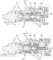
- Une vue en coupe à travers le boîtier de la pompe, au moment où la porte est fermée, ce qui provoque la fermeture de la pince ;
- Figure 2 :
- Une vue en coupe selon la
figure 1 , la porte est fermée et la poignée relâchée, la pince reste fermée ; - Figure 3 :
- Une vue en coupe selon la
figure 1 , la pince est ouverte par le dispositif d'ouverture ; - Figure 4 :
- Une vue en coupe selon la
figure 1 , au moment où la porte va être ouverte, la poignée étant soulevée, ce qui provoque la fermeture de la pince ; - Figure 5 :
- Une vue en coupe selon la
figure 1 , dans laquelle le fusible mécanique a sauté lorsqu'on a tenté d'ouvrir la porte au moment où la pince allait être ouverte selon lafigure 3 ; - Figure 6 :
- Une vue éclatée en perspective des éléments de la pince ;
- Figure 7 :
- Une vue en perspective de la porte ;
- Figure 8 :
- Une autre vue en perspective de la porte ;
- Figure 9 :
- Une vue en coupe du fusible mécanique en position de fonctionnement ; et
- Figure 10 :
- Une vue en coupe selon la
figure 9 du fusible mécanique ayant sauté.
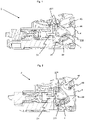
- Figure 1 :
- A sectional view through the pump housing, as the door is closed causing the clamp to close;
- Figure 2:
- A sectional view according to
figure 1 , the door is closed and the handle released, the clamp remains closed; - Figure 3:
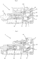
- A sectional view according to
figure 1 , the gripper is opened by the opening device; - Figure 4:
- A sectional view according to
figure 1 , when the door is about to be opened, the handle being raised, which causes the clamp to close; - Figure 5:
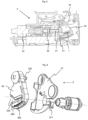
- A sectional view according to
figure 1 , in which the mechanical fuse blew when an attempt was made to open the door when the clamp was about to be opened according to thepicture 3 - Figure 6:
- An exploded perspective view of the gripper elements;
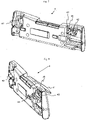
- Figure 7:
- A perspective view of the gate;
- Figure 8:
- Another perspective view of the gate;
- Figure 9:
- A sectional view of the mechanical fuse in the operating position; And
- Picture 10:
- A sectional view according to
figure 9 blown mechanical fuse.
Le dispositif de l'invention se compose essentiellement d'un tube (1) passant dans une pompe volumétrique non représentée et pouvant être fermé ou ouvert par une pince (2). La pompe ainsi que la pince (2) sont placées dans un boîtier (3) pouvant être fermé par une porte (4).The device of the invention essentially consists of a tube (1) passing through a volumetric pump, not shown, and which can be closed or opened by a clamp (2). The pump and the clamp (2) are placed in a box (3) which can be closed by a door (4).
Dans l'exemple présenté ici, on utilise une pince dite slide-clamp se composant de deux parties : une première partie fixe (21) et une partie mobile (22). Le tube (1) passe à travers une ouverture sensiblement cylindrique (211) qui a pour fonction notamment de le maintenir en place radialement. Cette partie fixe est solidaire du boîtier (3) et ne bouge pas. La partie mobile (22) au contraire peut pivoter autour d'un pivot (221) qui peut être logé par exemple dans la partie fixe (21) de la pince (2). Cette partie mobile (22) est munie d'une fente (222) s'ouvrant sur une partie (223) plus large. La largeur de la fente (222) est choisie de telle sorte que le tube (1) est aplati lorsqu'il se trouve engagé dedans se trouvant ainsi obstrué. Au contraire, l'ouverture (223) est suffisamment large pour que le tube (1) soit presque libre de toute contrainte lorsqu'il se trouve dedans de sorte qu'il retrouve sensiblement sa forme cylindrique normale laissant le passage au liquide pompé. Dans la pratique, le tube est maintenu dans une forme légèrement pincée qui facilite son entrée dans la fente (222). L'ouverture (223) est cependant suffisamment large pour ne pas perturber l'écoulement du liquide. Une section de transition (224) permet de faire passer le tube de la position libre de toute contrainte dans l'ouverture (223) à la position aplatie dans la fente (222). Cette partie mobile (22) de la pince (2) peut donc pivoter d'une position d'ouverture dans laquelle son ouverture (223) est sensiblement alignée avec l'ouverture (211) de la partie fixe, position dans laquelle le tube (1) est ouvert, à une position de fermeture dans laquelle l'ouverture (211) de la partie fixe est alignée avec la fente (222) de la partie mobile, position dans laquelle le tube aplati est fermé. La
La fermeture de la pince (2) est assurée par des moyens de fermeture fixés sur la porte (4). La porte (4) est munie d'une poignée (41) devant être pivotée pour permettre l'ouverture ou la fermeture de la porte (4). En faisant pivoter la poignée (41), on provoque le pivotement de crochets (42). Lorsque la poignée est en position rabattue, les crochets (42) crochètent des saillies correspondantes du boîtier (3) non représentées ici en empêchant l'ouverture involontaire de la porte (4). Quand la poignée (41) est en position pivotée, les crochets (42) se décrochent des saillies permettant l'ouverture de la porte (4). Pour ce faire, la poignée est montée sur un axe (43) sur lequel sont également montés les crochets (42). Outre ces crochets (42) nécessaires à l'ouverture et la fermeture de la porte, l'axe (43) porte également une came (44). Cette came (44) peut donc elle aussi pivoter entre une position pivotée où elle provoque lorsque la porte (4) est fermée le pivotement en position fermée de la partie mobile (22) de la pince (2), et une position rabattue dans laquelle elle ne bloque plus la partie mobile (22) en position fermée. La position pivotée de la came (44) est visible sur les
L'ouverture de la pince (2) est assurée par un doigt mobile (31) placé dans le boîtier (3) et actionné par un moteur (33). Ce doigt (31) en se déplaçant en translation vient appuyer sur la face de la partie mobile (22) de la pince (2) opposée à celle contre laquelle appuie la came (44). Ceci provoque le pivotement de la partie mobile (22) de sa position fermée vers sa position ouverte. Ce doigt mobile (31) associé au moteur (33) constitue les moyens pour provoquer l'ouverture de la pince (2) après que la porte a été fermée.The opening of the clamp (2) is provided by a movable finger (31) placed in the housing (3) and actuated by a motor (33). This finger (31) by moving in translation comes to press on the face of the movable part (22) of the gripper (2) opposite to that against which the cam (44) presses. This causes the movable part (22) to pivot from its closed position to its open position. This mobile finger (31) associated with the motor (33) constitutes the means for causing the opening of the gripper (2) after the door has been closed.
Le mode de fonctionnement du dispositif de contrôle selon l'invention est décrit ci-dessous en référence aux
Dès que la poignée est rabattue, la came (44) et les crochets (43) retournent dans leurs positions rabattues respectives comme le montre la
Le dispositif se trouve donc avec la porte (4) fermée et le tube (1) occlus. Il est maintenant possible par exemple de réaliser un test d'intégrité de la pompe sans que le liquide ne soit administré au patient. Si le résultat du test est favorable, le doigt (31) est actionné provoquant le pivotement en position ouverte de la partie mobile (22) de la pince (2). La poignée (4) étant rabattue, la came (44) n'entrave pas ce mouvement de pivot. On se retrouve dans la position présentée à la
Si pour une raison quelconque, la porte doit être ouverte, il faut tout d'abord faire pivoter la poignée (41) provoquant d'une part le pivotement des crochets (43) pour qu'ils se décrochent des saillies et d'autre part le pivotement de la came (44) ce qui provoque à son tour le pivotement de la partie mobile (22) de la pince (2). On se retrouve dans la position présentée à la
Il est impératif que la pince soit en position fermée lorsque la porte est ouverte. Autrement dit, si pour une raison quelconque, quelqu'un ouvre la porte au moment précis où le doigt (31) se déplace en translation pour provoquer le pivotement de la partie mobile (22) en position ouverte, il faut que le mouvement de fermeture de la pince (2) ait la priorité sur le mouvement inverse d'ouverture. De même, si l'ouverture est provoquée lorsque le doigt (31) est en position sortie, il faut pouvoir tout de même fermer la pince (2). Pour cela, il est prévu d'intercaler entre le moteur et le doigt (31) un fusible mécanique (32) qui cède si la pression à exercer sur le doigt (31) pour le déplacer en translation est supérieure à une valeur normale. La
Le mode de fonctionnement du fusible mécanique (32) est expliqué plus en détail aux
Si la came (44) bloque le mouvement de la partie pivotante (22) de la pince (2), comme dans le cas de la
De la même manière, si quelqu'un ouvre la porte (4) alors que le doigt (31) est encore sorti et la pince (2) en position ouverte comme sur la
Une fois la porte refermée, le fusible peut se réarmer automatiquement dès que le moteur (33) retourne dans sa position rétractée présentée par exemple à la
L'exemple de réalisation présenté ici fait appel à une pince dans laquelle le tube est pincé dans une fente pouvant pivoter. Il va de soi que la fente peut aussi avoir un mouvement de translation plutôt qu'un mouvement de pivot. De même, il est tout aussi bien possible d'utiliser une pince escargot (également connue sous le nom de pinch clamp) entre deux butées mobiles l'une par rapport à l'autre, que ce soit par translation ou par pivotement.The exemplary embodiment shown here uses a clamp in which the tube is clamped in a pivotable slot. It goes without saying that the slot can also have a translation movement rather than a pivot movement. Similarly, it is just as well possible to use a snail clamp (also known as a pinch clamp) between two movable stops relative to each other, whether by translation or by pivoting.
Le mouvement du doigt (31) ne doit pas être nécessairement une translation ; il peut très bien s'agir d'un mouvement de pivotement par exemple. De même, le moteur électrique peut être remplacé par une action manuelle ou un dispositif mécanique.The movement of the finger (31) does not have to be a translation; it may very well be a pivoting movement for example. Likewise, the electric motor can be replaced by a manual action or a mechanical device.
Avec le dispositif de sécurité de l'invention, on s'assure que le tube est non seulement toujours fermé lorsque la porte est en position ouverte mais également qu'il reste fermé une fois la porte fermée tant qu'un dispositif approprié n'a pas provoqué l'ouverture de la pince. Ce dispositif de fermeture entièrement mécanique n'est pas soumis aux aléas d'une alimentation électrique éventuellement défectueuse.With the safety device of the invention, it is ensured that the tube is not only always closed when the door is in the open position but also that it remains closed once the door is closed as long as a suitable device has not not caused the clamp to open. This entirely mechanical closing device is not subject to the vagaries of a possibly defective power supply.
- 1 Tube1 tube
-
2 Pince
- 21 Partie fixe
- 211 Ouverture cylindrique
- 22 Partie mobile
- 221 Pivot
- 222 Fente
- 223 Ouverture
- 224 Section de transition
- 21 Fixed part
- 211 Cylindrical opening
- 22 Moving part
- 221 Swivel
- 222 Slot
- 223 Opening
- 224 Transition section
- 21 Partie fixe
-
3 Boîtier de la pompe
- 31 Doigt
- 311 Encoches
- 32 Fusible mécanique
- 321 Crochets
- 322 Butée
- 323 Ressort
- 324 Biseau
- 33 Moteur
- 31 Finger
- 311 Notches
- 32 Mechanical fuse
- 321 Hooks
- 322 Stopper
- 323 Spring
- 324 Bevel
- 33 Engine
- 31 Doigt
-
4 Porte
- 41 Poignée
- 42 Crochets
- 43 Axe de pivotement de la poignée
- 44 Came
- 41 Handle
- 42 Hooks
- 43 Handle Pivot Pin
- 44 Cam
Claims (12)
- Method for controlling the opening or closing of a clamp (2) intended to seal a flexible tube (1) placed inside a housing (3) that can be closed with a door (4), the clamp (2) being placed in the housing (3) and cooperating with the tube (1) in order to open or seal it, wherein the clamp (2) passes from an open position to a closed position when the closing of the door is triggered, and stays in this closed position after closing of the door as long as opening means did not trigger the opening of the clamp,characterized inthat the clamp (2) passes from the open position to the closed position when the opening of the door (4) is triggered, wherein means (44) for closing the clamp (2), when the opening of the door (4) is triggered, and means (44) for closing the clamp (2), when the closing of the door (4) is triggered, are identical,wherein the means (44) for closing the clamp (2), when the opening of the door is triggered, and the means (44) for closing the clamp (2), when the closing of the door (4) is triggered, are activated by means (41, 43) for triggering the opening or the closing of the door (4).
- Method according to claim 1, characterized in that, once the door is closed, the clamp (2) is only opened when a predetermined event has occurred, in particular after an integrity test has been successfully conducted.
- Method according to claim 2, characterized in that the reopening of the clamp (2) is not effected when the opening of the door (4) is triggered at the same time.
- Device for controlling the opening or closing of a clamp (2) intended to seal a flexible tube (1), in particular in a positive displacement pump, comprising, among other things:- a housing (3) that can be closed with a door (4),- a tube (1) that is placed inside the housing (3), and- a clamp (2) that is placed inside the housing (3) and cooperates with the tube (1) in order to open or seal it,wherein means (44) are provided for passing the clamp (2) from an open position to a closed position when the closing of the door (4) is triggered, and wherein means (31) are provided for triggering the opening of the clamp (2) after the door (4) has been closed,characterized inthat means (44) are provided for passing the clamp (2) from an open position to a closed position when the opening of the door (4) is triggered, wherein the means (44) for closing the clamp (2), when the opening of the door (4) is triggered, and the means (44) for closing the clamp (2), when the closing of the door (4) is triggered, are identical,wherein the means (44) for closing the clamp (2), when the opening of the door is triggered, and the mans (44) for closing the clamp (2), when the closing of the door (4) is triggered, are activated by means (41, 43) for triggering the opening or the closing of the door (4).
- Device according to claim 4, characterized in that the means for triggering the opening or the closing of the door comprise a door handle (41) that is operable from the outside of the housing (3).
- Device according to claim 4 or 5, characterized in that the means (44) for closing the clamp (2), when the closing of the door (4) is triggered, and/or the means (44) for closing the clamp (2), when the opening of the door (4) is triggered, comprise a cam (44) that is able to cooperate with the means (41, 43) for triggering the opening or closing of the door (4).
- Device according to claim 6, characterized in that the cam is firmly connected to the axle (43) of the door handle (41).
- Device according to any of claims 4 to 7, characterized in that the clamp (2) consists of a slide clamp, which includes a stationary part (21) and a mobile part (22), preferably with rotational mobility, wherein the means for closing the clamp (2), when the closing of the door is triggered, or the means for closing the clamp (2), when the opening of the door is triggered, are dimensioned so as to make the mobile part (2) of the slide clamp slide relative to the stationary part (21).
- Device according to claims 4 to 8, characterized in that control means (33) are provided in order to activate the means (31) for opening the clamp (2) when a certain event has occurred.
- Device according to claim 9, characterized in that the control means are designed so as to activate the means (31) for opening the clamp (2) after a system integrity test has been conducted.
- Device according to any of claims 8 to 10, characterized in that a mechanical fuse (32) is provided for deactivating the means (31) for opening the clamp (2) when the opening of the door is effected at the moment the opening means are activated.
- Device according to any of claims 4 to 11, characterized in that it furthermore comprises a volumetric pump, preferably a peristaltic pump, that is connected to the tube (1), the volumetric pump preferably being placed upstream of the clamp (2).
Applications Claiming Priority (2)
| Application Number | Priority Date | Filing Date | Title |
|---|---|---|---|
| FR0609742A FR2908176B1 (en) | 2006-11-08 | 2006-11-08 | DEVICE FOR MONITORING THE OPENING OR CLOSING OF A CLAMP IN A VOLUMETRIC PUMP |
| PCT/EP2007/061548 WO2008055793A1 (en) | 2006-11-08 | 2007-10-26 | Device for controlling the opening and closing of a clamp in a positive displacement pump |
Publications (3)
| Publication Number | Publication Date |
|---|---|
| EP2089082A1 EP2089082A1 (en) | 2009-08-19 |
| EP2089082B1 EP2089082B1 (en) | 2015-05-20 |
| EP2089082B2 true EP2089082B2 (en) | 2023-02-22 |
Family
ID=37865786
Family Applications (1)
| Application Number | Title | Priority Date | Filing Date |
|---|---|---|---|
| EP07821908.6A Active EP2089082B2 (en) | 2006-11-08 | 2007-10-26 | Device for controlling the opening and closing of a clamp in a positive displacement pump |
Country Status (6)
| Country | Link |
|---|---|
| US (1) | US8109898B2 (en) |
| EP (1) | EP2089082B2 (en) |
| JP (1) | JP5089702B2 (en) |
| CN (1) | CN101528286B (en) |
| FR (1) | FR2908176B1 (en) |
| WO (1) | WO2008055793A1 (en) |
Families Citing this family (23)
| Publication number | Priority date | Publication date | Assignee | Title |
|---|---|---|---|---|
| US9028691B2 (en) | 2007-02-27 | 2015-05-12 | Deka Products Limited Partnership | Blood circuit assembly for a hemodialysis system |
| US10201647B2 (en) | 2008-01-23 | 2019-02-12 | Deka Products Limited Partnership | Medical treatment system and methods using a plurality of fluid lines |
| US11833281B2 (en) | 2008-01-23 | 2023-12-05 | Deka Products Limited Partnership | Pump cassette and methods for use in medical treatment system using a plurality of fluid lines |
| US9677555B2 (en) | 2011-12-21 | 2017-06-13 | Deka Products Limited Partnership | System, method, and apparatus for infusing fluid |
| US9675756B2 (en) | 2011-12-21 | 2017-06-13 | Deka Products Limited Partnership | Apparatus for infusing fluid |
| US11295846B2 (en) | 2011-12-21 | 2022-04-05 | Deka Products Limited Partnership | System, method, and apparatus for infusing fluid |
| EP2832388B1 (en) * | 2012-03-26 | 2016-11-16 | Terumo Kabushiki Kaisha | Infusion pump |
| CN112138240B (en) * | 2012-05-24 | 2023-04-07 | 德卡产品有限公司 | Device for infusing fluid |
| US9364655B2 (en) * | 2012-05-24 | 2016-06-14 | Deka Products Limited Partnership | Flexible tubing occlusion assembly |
| DE102013014217A1 (en) * | 2013-08-26 | 2015-02-26 | Thomas Magnete Gmbh | Hose clamp for holding and closing a hose |
| WO2016044146A2 (en) | 2014-09-18 | 2016-03-24 | Deka Products Limited Partnership | Apparatus and method for infusing fluid through a tube by appropriately heating the tube |
| EP4252798A3 (en) | 2015-06-04 | 2023-10-25 | Medimop Medical Projects Ltd. | Cartridge insertion for drug delivery device |
| WO2017033947A1 (en) * | 2015-08-25 | 2017-03-02 | 株式会社村田製作所 | Fluid control device |
| US10167861B2 (en) * | 2016-05-26 | 2019-01-01 | Namiki Precision Singapore Pte. Ltd. | Infusion pump |
| DE102017115862A1 (en) * | 2017-07-14 | 2019-01-17 | B. Braun Melsungen Ag | Device for controlling the opening and closing of a hose |
| DE102017116106A1 (en) * | 2017-07-18 | 2019-01-24 | B. Braun Melsungen Ag | Device and method for opening and closing an infusion tube clamp |
| US11642457B2 (en) * | 2017-08-10 | 2023-05-09 | West Pharma. Services IL, Ltd. | Injector self-test and injector door unlocking mechanism responsive thereto |
| EP3727514A1 (en) | 2017-12-22 | 2020-10-28 | West Pharma Services IL, Ltd. | Injector usable with different dimension cartridges |
| CN112512620B (en) * | 2018-05-04 | 2024-01-26 | 费森尤斯维尔公司 | Infusion device comprising a clamping device |
| CN112261958B (en) * | 2018-06-18 | 2023-11-21 | 费森尤斯维尔公司 | Infusion device comprising a clamping mechanism |
| USD917045S1 (en) | 2018-08-16 | 2021-04-20 | Deka Products Limited Partnership | Slide clamp |
| KR20210042378A (en) * | 2018-08-16 | 2021-04-19 | 데카 프로덕츠 리미티드 파트너쉽 | Medical pump |
| USD1004412S1 (en) | 2019-08-16 | 2023-11-14 | Deka Products Limited Partnership | Slide clamp assembly |
Citations (2)
| Publication number | Priority date | Publication date | Assignee | Title |
|---|---|---|---|---|
| EP0510881A2 (en) † | 1991-04-23 | 1992-10-28 | Minnesota Mining And Manufacturing Company | Free flow prevention system for infusion pump |
| WO2003041787A2 (en) † | 2001-11-15 | 2003-05-22 | Arcomed Ag | Safety device for an infusion pump |
Family Cites Families (6)
| Publication number | Priority date | Publication date | Assignee | Title |
|---|---|---|---|---|
| US4689043A (en) | 1986-03-19 | 1987-08-25 | Imed Corporation | IV tube activator |
| US5290239A (en) * | 1991-09-26 | 1994-03-01 | Baxter International, Inc. | Intravenous tube safety apparatus |
| US6261262B1 (en) * | 1997-06-12 | 2001-07-17 | Abbott Laboratories | Pump with anti-free flow feature |
| FR2790041B1 (en) * | 1999-02-23 | 2002-01-18 | Fresenius Vial | METHOD FOR CONTROLLING A PUMPING DEVICE COMPRISING A PUMP PROVIDED WITH A FLEXIBLE TUBE AND DEVICE FOR IMPLEMENTING THE METHOD |
| DE19947973C2 (en) | 1999-10-05 | 2003-06-26 | Fresenius Ag | Unit of an infusion pump with an infusion tubing set, as well as a hose clamp, infusion pump and infusion tubing set |
| US6629955B2 (en) * | 2001-05-04 | 2003-10-07 | Alaris Medical Systems, Inc. | Medical instrument flow stop interface |
-
2006
- 2006-11-08 FR FR0609742A patent/FR2908176B1/en active Active
-
2007
- 2007-10-26 WO PCT/EP2007/061548 patent/WO2008055793A1/en active Application Filing
- 2007-10-26 JP JP2009535060A patent/JP5089702B2/en not_active Expired - Fee Related
- 2007-10-26 US US12/513,785 patent/US8109898B2/en active Active
- 2007-10-26 CN CN2007800392896A patent/CN101528286B/en not_active Expired - Fee Related
- 2007-10-26 EP EP07821908.6A patent/EP2089082B2/en active Active
Patent Citations (2)
| Publication number | Priority date | Publication date | Assignee | Title |
|---|---|---|---|---|
| EP0510881A2 (en) † | 1991-04-23 | 1992-10-28 | Minnesota Mining And Manufacturing Company | Free flow prevention system for infusion pump |
| WO2003041787A2 (en) † | 2001-11-15 | 2003-05-22 | Arcomed Ag | Safety device for an infusion pump |
Non-Patent Citations (1)
| Title |
|---|
| "Infusomat Space P", GEBRAUCHSANWEISUNG, January 2006 (2006-01-01) † |
Also Published As
| Publication number | Publication date |
|---|---|
| WO2008055793A1 (en) | 2008-05-15 |
| CN101528286B (en) | 2012-02-01 |
| US20100040481A1 (en) | 2010-02-18 |
| FR2908176B1 (en) | 2008-12-19 |
| FR2908176A1 (en) | 2008-05-09 |
| JP2010508876A (en) | 2010-03-25 |
| CN101528286A (en) | 2009-09-09 |
| EP2089082A1 (en) | 2009-08-19 |
| EP2089082B1 (en) | 2015-05-20 |
| US8109898B2 (en) | 2012-02-07 |
| JP5089702B2 (en) | 2012-12-05 |
Similar Documents
| Publication | Publication Date | Title |
|---|---|---|
| EP2089082B2 (en) | Device for controlling the opening and closing of a clamp in a positive displacement pump | |
| EP1846063B1 (en) | Holding device for locking the head of a syringe piston on a syringe pump pusher | |
| EP2183016B1 (en) | Clamp for a flexible tube, pump provided with means for opening such a clamp, and infusion kit provided with such a clamp | |
| EP2766121B1 (en) | Highly safe control mechanism for a device for the sealed transfer between two closed spaces | |
| EP2310141B1 (en) | Fluid product dispensing device | |
| EP2319376B1 (en) | System for producing beverages by infusion | |
| EP3581742B1 (en) | Door flush handle and method of operating the same | |
| EP0190976B1 (en) | Vehicle door closer | |
| EP1734552B1 (en) | Actuating device for an electrical switch device with rotational locking means | |
| EP0897310A1 (en) | Pinch obturating device for flexible tube | |
| EP1673530B1 (en) | Thrust reverser lock comprising locking device | |
| EP2717284B1 (en) | Operating device of an electric protection apparatus and electric protection apparatus comprising same | |
| EP1655445A2 (en) | Operating device for ventilating system made of rotatable lamellae with emergency opening | |
| EP1026345B1 (en) | Lock comprising a system for electrically assisted opening of a vehicle wing | |
| EP3922791A1 (en) | Electric door locking mechanism comprising a mechanical back-up function | |
| EP2204828B1 (en) | Mechanism for coupling a high- or medium-voltage switchgear control, with improved compactness and cost | |
| EP3657522B1 (en) | Mechanism for controlling the opening and closing of a current interruption device for an electrical switch | |
| EP2371628A1 (en) | Device for cutting a cable crossing the way of a vehicle | |
| FR2773836A1 (en) | MOTOR VEHICLE DOOR CLOSURE | |
| FR2889961A1 (en) | Syringe maintaining device, has slit limiting longitudinal clearance and longitudinal movement of syringe body with respect to receptacle, where slit has lever stop to lock blade of body against stop of case of pump | |
| FR2737152A1 (en) | Thermal printer mechanism convertible from fixed to retractable roller - includes drive roller which is pivotable about axis and selectively mountable on print head carrier support or on tiltable cover of paper housing. | |
| WO2020128185A1 (en) | Foldable crank arm | |
| BE402871A (en) | ||
| EP1338484A1 (en) | Protection device for pedestrians in case of impact with a vehicle and a vehicle equipped with such a device | |
| EP1619073A1 (en) | Arm mechanism, especially for handling, with a translatory motion followed by a rotary motion |
Legal Events
| Date | Code | Title | Description |
|---|---|---|---|
| PUAI | Public reference made under article 153(3) epc to a published international application that has entered the european phase |
Free format text: ORIGINAL CODE: 0009012 |
|
| 17P | Request for examination filed |
Effective date: 20090313 |
|
| AK | Designated contracting states |
Kind code of ref document: A1 Designated state(s): AT BE BG CH CY CZ DE DK EE ES FI FR GB GR HU IE IS IT LI LT LU LV MC MT NL PL PT RO SE SI SK TR |
|
| DAX | Request for extension of the european patent (deleted) | ||
| 17Q | First examination report despatched |
Effective date: 20110728 |
|
| REG | Reference to a national code |
Ref country code: DE Ref legal event code: R079 Ref document number: 602007041520 Country of ref document: DE Free format text: PREVIOUS MAIN CLASS: A61M0005168000 Ipc: A61M0005142000 |
|
| RIC1 | Information provided on ipc code assigned before grant |
Ipc: A61M 39/28 20060101ALI20141030BHEP Ipc: A61M 5/142 20060101AFI20141030BHEP Ipc: A61M 5/168 20060101ALI20141030BHEP |
|
| GRAP | Despatch of communication of intention to grant a patent |
Free format text: ORIGINAL CODE: EPIDOSNIGR1 |
|
| INTG | Intention to grant announced |
Effective date: 20150113 |
|
| GRAS | Grant fee paid |
Free format text: ORIGINAL CODE: EPIDOSNIGR3 |
|
| GRAA | (expected) grant |
Free format text: ORIGINAL CODE: 0009210 |
|
| STAA | Information on the status of an ep patent application or granted ep patent |
Free format text: STATUS: THE PATENT HAS BEEN GRANTED |
|
| AK | Designated contracting states |
Kind code of ref document: B1 Designated state(s): AT BE BG CH CY CZ DE DK EE ES FI FR GB GR HU IE IS IT LI LT LU LV MC MT NL PL PT RO SE SI SK TR |
|
| REG | Reference to a national code |
Ref country code: GB Ref legal event code: FG4D Free format text: NOT ENGLISH |
|
| REG | Reference to a national code |
Ref country code: CH Ref legal event code: EP |
|
| REG | Reference to a national code |
Ref country code: AT Ref legal event code: REF Ref document number: 727415 Country of ref document: AT Kind code of ref document: T Effective date: 20150615 |
|
| REG | Reference to a national code |
Ref country code: IE Ref legal event code: FG4D Free format text: LANGUAGE OF EP DOCUMENT: FRENCH |
|
| REG | Reference to a national code |
Ref document number: 602007041520 Ref country code: DE Ref legal event code: R096 Ref document number: 602007041520 Country of ref document: DE Effective date: 20150702 |
|
| REG | Reference to a national code |
Ref country code: AT Ref legal event code: MK05 Ref document number: 727415 Country of ref document: AT Kind code of ref document: T Effective date: 20150520 |
|
| REG | Reference to a national code |
Ref country code: FR Ref legal event code: PLFP Year of fee payment: 9 |
|
| REG | Reference to a national code |
Ref country code: LT Ref legal event code: MG4D |
|
| REG | Reference to a national code |
Ref country code: NL Ref legal event code: MP Effective date: 20150520 |
|
| PG25 | Lapsed in a contracting state [announced via postgrant information from national office to epo] |
Ref country code: ES Free format text: LAPSE BECAUSE OF FAILURE TO SUBMIT A TRANSLATION OF THE DESCRIPTION OR TO PAY THE FEE WITHIN THE PRESCRIBED TIME-LIMIT Effective date: 20150520 Ref country code: PT Free format text: LAPSE BECAUSE OF FAILURE TO SUBMIT A TRANSLATION OF THE DESCRIPTION OR TO PAY THE FEE WITHIN THE PRESCRIBED TIME-LIMIT Effective date: 20150921 Ref country code: LT Free format text: LAPSE BECAUSE OF FAILURE TO SUBMIT A TRANSLATION OF THE DESCRIPTION OR TO PAY THE FEE WITHIN THE PRESCRIBED TIME-LIMIT Effective date: 20150520 Ref country code: FI Free format text: LAPSE BECAUSE OF FAILURE TO SUBMIT A TRANSLATION OF THE DESCRIPTION OR TO PAY THE FEE WITHIN THE PRESCRIBED TIME-LIMIT Effective date: 20150520 |
|
| PG25 | Lapsed in a contracting state [announced via postgrant information from national office to epo] |
Ref country code: IS Free format text: LAPSE BECAUSE OF FAILURE TO SUBMIT A TRANSLATION OF THE DESCRIPTION OR TO PAY THE FEE WITHIN THE PRESCRIBED TIME-LIMIT Effective date: 20150920 Ref country code: LV Free format text: LAPSE BECAUSE OF FAILURE TO SUBMIT A TRANSLATION OF THE DESCRIPTION OR TO PAY THE FEE WITHIN THE PRESCRIBED TIME-LIMIT Effective date: 20150520 Ref country code: AT Free format text: LAPSE BECAUSE OF FAILURE TO SUBMIT A TRANSLATION OF THE DESCRIPTION OR TO PAY THE FEE WITHIN THE PRESCRIBED TIME-LIMIT Effective date: 20150520 Ref country code: BG Free format text: LAPSE BECAUSE OF FAILURE TO SUBMIT A TRANSLATION OF THE DESCRIPTION OR TO PAY THE FEE WITHIN THE PRESCRIBED TIME-LIMIT Effective date: 20150820 Ref country code: GR Free format text: LAPSE BECAUSE OF FAILURE TO SUBMIT A TRANSLATION OF THE DESCRIPTION OR TO PAY THE FEE WITHIN THE PRESCRIBED TIME-LIMIT Effective date: 20150821 |
|
| PG25 | Lapsed in a contracting state [announced via postgrant information from national office to epo] |
Ref country code: EE Free format text: LAPSE BECAUSE OF FAILURE TO SUBMIT A TRANSLATION OF THE DESCRIPTION OR TO PAY THE FEE WITHIN THE PRESCRIBED TIME-LIMIT Effective date: 20150520 Ref country code: DK Free format text: LAPSE BECAUSE OF FAILURE TO SUBMIT A TRANSLATION OF THE DESCRIPTION OR TO PAY THE FEE WITHIN THE PRESCRIBED TIME-LIMIT Effective date: 20150520 |
|
| REG | Reference to a national code |
Ref country code: DE Ref legal event code: R026 Ref document number: 602007041520 Country of ref document: DE |
|
| PLBI | Opposition filed |
Free format text: ORIGINAL CODE: 0009260 |
|
| PG25 | Lapsed in a contracting state [announced via postgrant information from national office to epo] |
Ref country code: CZ Free format text: LAPSE BECAUSE OF FAILURE TO SUBMIT A TRANSLATION OF THE DESCRIPTION OR TO PAY THE FEE WITHIN THE PRESCRIBED TIME-LIMIT Effective date: 20150520 Ref country code: RO Free format text: LAPSE BECAUSE OF NON-PAYMENT OF DUE FEES Effective date: 20150520 Ref country code: SK Free format text: LAPSE BECAUSE OF FAILURE TO SUBMIT A TRANSLATION OF THE DESCRIPTION OR TO PAY THE FEE WITHIN THE PRESCRIBED TIME-LIMIT Effective date: 20150520 Ref country code: PL Free format text: LAPSE BECAUSE OF FAILURE TO SUBMIT A TRANSLATION OF THE DESCRIPTION OR TO PAY THE FEE WITHIN THE PRESCRIBED TIME-LIMIT Effective date: 20150520 |
|
| 26 | Opposition filed |
Opponent name: B. BRAUN MELSUNGEN AG Effective date: 20160212 |
|
| PLAX | Notice of opposition and request to file observation + time limit sent |
Free format text: ORIGINAL CODE: EPIDOSNOBS2 |
|
| PG25 | Lapsed in a contracting state [announced via postgrant information from national office to epo] |
Ref country code: IT Free format text: LAPSE BECAUSE OF FAILURE TO SUBMIT A TRANSLATION OF THE DESCRIPTION OR TO PAY THE FEE WITHIN THE PRESCRIBED TIME-LIMIT Effective date: 20150520 |
|
| PG25 | Lapsed in a contracting state [announced via postgrant information from national office to epo] |
Ref country code: SI Free format text: LAPSE BECAUSE OF FAILURE TO SUBMIT A TRANSLATION OF THE DESCRIPTION OR TO PAY THE FEE WITHIN THE PRESCRIBED TIME-LIMIT Effective date: 20150520 Ref country code: LU Free format text: LAPSE BECAUSE OF FAILURE TO SUBMIT A TRANSLATION OF THE DESCRIPTION OR TO PAY THE FEE WITHIN THE PRESCRIBED TIME-LIMIT Effective date: 20151026 |
|
| REG | Reference to a national code |
Ref country code: CH Ref legal event code: PL |
|
| PG25 | Lapsed in a contracting state [announced via postgrant information from national office to epo] |
Ref country code: MC Free format text: LAPSE BECAUSE OF FAILURE TO SUBMIT A TRANSLATION OF THE DESCRIPTION OR TO PAY THE FEE WITHIN THE PRESCRIBED TIME-LIMIT Effective date: 20150520 |
|
| PLAB | Opposition data, opponent's data or that of the opponent's representative modified |
Free format text: ORIGINAL CODE: 0009299OPPO |
|
| PLAF | Information modified related to communication of a notice of opposition and request to file observations + time limit |
Free format text: ORIGINAL CODE: EPIDOSCOBS2 |
|
| REG | Reference to a national code |
Ref country code: IE Ref legal event code: MM4A |
|
| PG25 | Lapsed in a contracting state [announced via postgrant information from national office to epo] |
Ref country code: LI Free format text: LAPSE BECAUSE OF NON-PAYMENT OF DUE FEES Effective date: 20151031 Ref country code: CH Free format text: LAPSE BECAUSE OF NON-PAYMENT OF DUE FEES Effective date: 20151031 |
|
| R26 | Opposition filed (corrected) |
Opponent name: B. BRAUN MELSUNGEN AG Effective date: 20160212 |
|
| PLBB | Reply of patent proprietor to notice(s) of opposition received |
Free format text: ORIGINAL CODE: EPIDOSNOBS3 |
|
| REG | Reference to a national code |
Ref country code: FR Ref legal event code: PLFP Year of fee payment: 10 |
|
| PG25 | Lapsed in a contracting state [announced via postgrant information from national office to epo] |
Ref country code: IE Free format text: LAPSE BECAUSE OF NON-PAYMENT OF DUE FEES Effective date: 20151026 |
|
| PG25 | Lapsed in a contracting state [announced via postgrant information from national office to epo] |
Ref country code: HU Free format text: LAPSE BECAUSE OF FAILURE TO SUBMIT A TRANSLATION OF THE DESCRIPTION OR TO PAY THE FEE WITHIN THE PRESCRIBED TIME-LIMIT; INVALID AB INITIO Effective date: 20071026 |
|
| PG25 | Lapsed in a contracting state [announced via postgrant information from national office to epo] |
Ref country code: CY Free format text: LAPSE BECAUSE OF FAILURE TO SUBMIT A TRANSLATION OF THE DESCRIPTION OR TO PAY THE FEE WITHIN THE PRESCRIBED TIME-LIMIT Effective date: 20150520 Ref country code: NL Free format text: LAPSE BECAUSE OF FAILURE TO SUBMIT A TRANSLATION OF THE DESCRIPTION OR TO PAY THE FEE WITHIN THE PRESCRIBED TIME-LIMIT Effective date: 20150520 Ref country code: SE Free format text: LAPSE BECAUSE OF FAILURE TO SUBMIT A TRANSLATION OF THE DESCRIPTION OR TO PAY THE FEE WITHIN THE PRESCRIBED TIME-LIMIT Effective date: 20150520 |
|
| PG25 | Lapsed in a contracting state [announced via postgrant information from national office to epo] |
Ref country code: BE Free format text: LAPSE BECAUSE OF NON-PAYMENT OF DUE FEES Effective date: 20151031 |
|
| PG25 | Lapsed in a contracting state [announced via postgrant information from national office to epo] |
Ref country code: TR Free format text: LAPSE BECAUSE OF FAILURE TO SUBMIT A TRANSLATION OF THE DESCRIPTION OR TO PAY THE FEE WITHIN THE PRESCRIBED TIME-LIMIT Effective date: 20150520 Ref country code: MT Free format text: LAPSE BECAUSE OF FAILURE TO SUBMIT A TRANSLATION OF THE DESCRIPTION OR TO PAY THE FEE WITHIN THE PRESCRIBED TIME-LIMIT Effective date: 20150520 |
|
| REG | Reference to a national code |
Ref country code: FR Ref legal event code: PLFP Year of fee payment: 11 |
|
| APAH | Appeal reference modified |
Free format text: ORIGINAL CODE: EPIDOSCREFNO |
|
| APBM | Appeal reference recorded |
Free format text: ORIGINAL CODE: EPIDOSNREFNO |
|
| APBP | Date of receipt of notice of appeal recorded |
Free format text: ORIGINAL CODE: EPIDOSNNOA2O |
|
| APBQ | Date of receipt of statement of grounds of appeal recorded |
Free format text: ORIGINAL CODE: EPIDOSNNOA3O |
|
| REG | Reference to a national code |
Ref country code: FR Ref legal event code: PLFP Year of fee payment: 12 |
|
| APBU | Appeal procedure closed |
Free format text: ORIGINAL CODE: EPIDOSNNOA9O |
|
| PUAH | Patent maintained in amended form |
Free format text: ORIGINAL CODE: 0009272 |
|
| STAA | Information on the status of an ep patent application or granted ep patent |
Free format text: STATUS: PATENT MAINTAINED AS AMENDED |
|
| 27A | Patent maintained in amended form |
Effective date: 20230222 |
|
| AK | Designated contracting states |
Kind code of ref document: B2 Designated state(s): AT BE BG CH CY CZ DE DK EE ES FI FR GB GR HU IE IS IT LI LT LU LV MC MT NL PL PT RO SE SI SK TR |
|
| REG | Reference to a national code |
Ref country code: DE Ref legal event code: R102 Ref document number: 602007041520 Country of ref document: DE |
|
| P01 | Opt-out of the competence of the unified patent court (upc) registered |
Effective date: 20230528 |
|
| PGFP | Annual fee paid to national office [announced via postgrant information from national office to epo] |
Ref country code: GB Payment date: 20231027 Year of fee payment: 17 |
|
| PGFP | Annual fee paid to national office [announced via postgrant information from national office to epo] |
Ref country code: FR Payment date: 20231025 Year of fee payment: 17 Ref country code: DE Payment date: 20231027 Year of fee payment: 17 |