EP2088558B1 - Dispositif de détection de vecteur de mouvement - Google Patents
Dispositif de détection de vecteur de mouvement Download PDFInfo
- Publication number
- EP2088558B1 EP2088558B1 EP07745013A EP07745013A EP2088558B1 EP 2088558 B1 EP2088558 B1 EP 2088558B1 EP 07745013 A EP07745013 A EP 07745013A EP 07745013 A EP07745013 A EP 07745013A EP 2088558 B1 EP2088558 B1 EP 2088558B1
- Authority
- EP
- European Patent Office
- Prior art keywords
- horizontal
- value
- vertical
- data
- block
- Prior art date
- Legal status (The legal status is an assumption and is not a legal conclusion. Google has not performed a legal analysis and makes no representation as to the accuracy of the status listed.)
- Not-in-force
Links
Images


Classifications
-
- H—ELECTRICITY
- H04—ELECTRIC COMMUNICATION TECHNIQUE
- H04N—PICTORIAL COMMUNICATION, e.g. TELEVISION
- H04N5/00—Details of television systems
- H04N5/14—Picture signal circuitry for video frequency region
- H04N5/144—Movement detection
- H04N5/145—Movement estimation
-
- G—PHYSICS
- G06—COMPUTING; CALCULATING OR COUNTING
- G06T—IMAGE DATA PROCESSING OR GENERATION, IN GENERAL
- G06T7/00—Image analysis
- G06T7/20—Analysis of motion
- G06T7/246—Analysis of motion using feature-based methods, e.g. the tracking of corners or segments
-
- H—ELECTRICITY
- H04—ELECTRIC COMMUNICATION TECHNIQUE
- H04N—PICTORIAL COMMUNICATION, e.g. TELEVISION
- H04N19/00—Methods or arrangements for coding, decoding, compressing or decompressing digital video signals
- H04N19/10—Methods or arrangements for coding, decoding, compressing or decompressing digital video signals using adaptive coding
- H04N19/134—Methods or arrangements for coding, decoding, compressing or decompressing digital video signals using adaptive coding characterised by the element, parameter or criterion affecting or controlling the adaptive coding
- H04N19/136—Incoming video signal characteristics or properties
- H04N19/14—Coding unit complexity, e.g. amount of activity or edge presence estimation
-
- H—ELECTRICITY
- H04—ELECTRIC COMMUNICATION TECHNIQUE
- H04N—PICTORIAL COMMUNICATION, e.g. TELEVISION
- H04N19/00—Methods or arrangements for coding, decoding, compressing or decompressing digital video signals
- H04N19/50—Methods or arrangements for coding, decoding, compressing or decompressing digital video signals using predictive coding
- H04N19/503—Methods or arrangements for coding, decoding, compressing or decompressing digital video signals using predictive coding involving temporal prediction
- H04N19/51—Motion estimation or motion compensation
- H04N19/513—Processing of motion vectors
- H04N19/521—Processing of motion vectors for estimating the reliability of the determined motion vectors or motion vector field, e.g. for smoothing the motion vector field or for correcting motion vectors
-
- H—ELECTRICITY
- H04—ELECTRIC COMMUNICATION TECHNIQUE
- H04N—PICTORIAL COMMUNICATION, e.g. TELEVISION
- H04N19/00—Methods or arrangements for coding, decoding, compressing or decompressing digital video signals
- H04N19/80—Details of filtering operations specially adapted for video compression, e.g. for pixel interpolation
-
- H—ELECTRICITY
- H04—ELECTRIC COMMUNICATION TECHNIQUE
- H04N—PICTORIAL COMMUNICATION, e.g. TELEVISION
- H04N23/00—Cameras or camera modules comprising electronic image sensors; Control thereof
- H04N23/60—Control of cameras or camera modules
- H04N23/68—Control of cameras or camera modules for stable pick-up of the scene, e.g. compensating for camera body vibrations
- H04N23/681—Motion detection
- H04N23/6811—Motion detection based on the image signal
-
- G—PHYSICS
- G06—COMPUTING; CALCULATING OR COUNTING
- G06T—IMAGE DATA PROCESSING OR GENERATION, IN GENERAL
- G06T2207/00—Indexing scheme for image analysis or image enhancement
- G06T2207/10—Image acquisition modality
- G06T2207/10016—Video; Image sequence
-
- G—PHYSICS
- G06—COMPUTING; CALCULATING OR COUNTING
- G06T—IMAGE DATA PROCESSING OR GENERATION, IN GENERAL
- G06T2207/00—Indexing scheme for image analysis or image enhancement
- G06T2207/20—Special algorithmic details
- G06T2207/20068—Projection on vertical or horizontal image axis
-
- G—PHYSICS
- G06—COMPUTING; CALCULATING OR COUNTING
- G06T—IMAGE DATA PROCESSING OR GENERATION, IN GENERAL
- G06T2207/00—Indexing scheme for image analysis or image enhancement
- G06T2207/20—Special algorithmic details
- G06T2207/20172—Image enhancement details
- G06T2207/20192—Edge enhancement; Edge preservation
Definitions
- the present invention relates to a motion-vector detection device for detecting a motion vector between frame images of a preceding frame and a succeeding frame adjacent to each other in time sequence.
- Patent document 1 Patent gazette No. 3164121
- the motion vector detection method disclosed in Patent document 1 reduces misjudgments by giving weight to the reliability of a motion vector calculated per block with the number of edges per block, but has a problem in that it is difficult to estimate the reliability of a motion vector in some detecting conditions.
- the difference arises in the reliability of the calculated motion vector, depending on the relation between its period and a motion detecting range. If the motion detecting range is smaller than the period, it appears to be easy to calculate a motion vector having reliability, however, if the motion detecting range is larger than the period, it appears to be difficult to calculate a motion vector having reliability. Further, even if a different motion is seen in a part of a subject photographed, the difference arises in the reliability of the calculated motion vector, depending on the extent of the motion. That is, when the motion of the part is small, a motion of the whole subject photographed can be properly detected, however, when a part of the motion is large, the motion of the whole subject photographed cannot be properly detected without being bothered by its motion, being affected by the motion.
- Techniques for detecting a motion vector between frame images for use in hand shake correction or the like include one, as described in Patent document 2, that compares a pixel value with an adjacent pixel per pixel from a difference image per a plurality of time sequentially images, estimates a direction of a motion per direction, and calculates an average of the sum of a motion vector thereof to obtain a motion vector per pixel, thereby calculating a local motion vector (an optical flow).
- a smoothing process is performed to an optical flow obtained per pixel in order to lower (reduce) an influence of noise, such as averaging the sum of initially-estimated motion vectors including peripheral eight pixels.
- Patent document 3 discloses the same smoothing method as Patent document 2 applied to a projection data, dividing an input image into each partial region, and calculating a motion vector of the entire image using a motion vector calculated per a plurality of partial regions.
- a low-pass filter of 3-tap consisted of 1/4, 1/2 and 1/4 as shown in Fig. 2 of Patent document 4 is often used.
- the calculated motion vector is smoothed by taking the average between the calculated motion vector and the results of peripheral pixels, and noise is not removed in an original image used for calculating a motion vector, and in a projection data itself. Therefore, the problem arises that the motion vector is not accurately calculated if noise affects even peripheral pixels because a motion vector is calculated by using data including noise.
- WO 2006/101032 A1 relates to an image motion vector detecting device.
- the line memory 4H stores the output of the edge extraction filtering means corresponding to the one frame, and outputs data on the previous frame earlier by one frame to threshold intersection decision means. This means finds points intersected between a signal and the input threshold.
- Signal integration means generates a signal obtained by shifting the row data of the current frame by the amount of t+1, t+2, and so on. The generated signals are then used to calculate an average.
- peak decision means determines a peak in a curved line, there may occur a situation in which a plurality of small peaks appears and a single peak does not appear.
- Joon Ki Paik et al "An adaptive motion decision system for digital image stabilizer based on edge pattern matching", IEEE Transactions on consume electronics, IEEE service center, New York, US 1 August 1992 relates to the effect of various environmental conditions which degrade the performance of a digital image stabilization system in a video camera.
- a new DIS system with an adaptive motion decision system, based on the analysis, is proposed.
- the proposed DIS system is composed of: (i) a local motion vector generation unit, (ii) a field motion vector generation unit, (iii) and accumulated motion vector generation unit, and (iv) field memory address control and digital zooming unit.
- Sekine M et al "Motion Vector Detecting System for Video Image Stabilizers", 21 June 1994 relates to a motion vector detecting system that computes 50 vectors from the video signal by the binary image matching method. It detects accurate motion vectors in various light conditions, and a vector integration technique enables the stabilizer to work naturally during zooming, rolling and tracking.
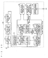
- Fig. 1 is a block diagram showing an essential configuration of a motion-vector detection device 1 according to a first embodiment of the present invention.
- the motion-vector detection device 1 is intended to detect an image motion vector indicative of the motion of a subject in a screen in moving images, for example, and detects a motion vector between frame images of a preceding frame and a succeeding frame adjacent to each other in time sequence.
- the motion vector detected in this motion-vector detection device I is used for hand shake correction in a video camera or the like.
- Frame images input to the motion-vector detection device 1 shall be read by carrying out pixel scanning in the horizontal direction and line scanning in the vertical direction, as shown in Fig. 2 .
- the motion-vector detection device 1 includes an input terminal 11, a horizontal-motion-vector detecting section 2, a vertical-motion-vector detecting section 4, and two output terminals 12, 13. Regarding these horizontal-motion-vector detecting section 2 and vertical-motion-vector detecting section 4, their functions may be achieved by software by a microprocessor, for example, or most part thereof may be achieved by hardware (other part by software). It is needless to say that all the functions may be achieved by hardware.
- image data (moving images) acquired by an imaging device within a video camera or image data such as vide- signals is input to the input terminal 11.
- a horizontal motion vector of the image data input to the input terminal 11 is detected in the horizontal-motion-vector detecting section 2, and the detected horizontal motion vector is output through the output terminal 12.
- the vertical-motion-vector detecting section 4 detects a vertical motion vector of the image data input to the input terminal 11. This vertical motion vector detected by the vertical-motion-vector detecting section 4 is output through the output terminal 13.
- Fig. 3 is a block diagram showing an essential configuration of the horizontal-motion-vector detecting section 2.
- the horizontal-motion-vector detecting section 2 includes an input terminal 20, a vertical image-dividing part 21, a vertical-edge detection filtering part 22, a vertical-block projecting part 23, a first vertical-block projection-data maximum-value storage part 24, a bit-number reducing part 25, a first vertical-block projection line memory 26.
- the horizontal-motion-vector detecting section 2 further includes a second vertical-block projection line memory 27, a second vertical-block projection-data maximum-value storage part 28, a first-threshold intersection searching part 29, a vertical-block projection-data reading part 30, a vertical-block horizontal-motion-vector calculating part 31, a horizontal-motion-vector determining part 32, and an output terminal 33. Functions of the respective parts of the horizontal-motion-vector detecting section 2 will be described briefly (specific operations will be described later in detail).
- the vertical image-dividing part 21 divides a frame image input to the input terminal 20 in the vertical direction, and outputs blocks divided vertically (hereinafter also called “vertical blocks").
- the vertical-edge detection filtering part 22 carries out a filtering process for performing edge detection in each of the blocks divided by the vertical image-dividing part 21.
- the vertical-block projecting part 23 obtains a vertical projection of an edge-enhanced vertical block output from the vertical-edge detection filtering part 22, and outputs projection data for each vertical block.
- the first vertical-block projection-data maximum-value storage part 24 stores the maximum value of projection data of vertical blocks of the current frame output from the vertical-block projecting part 23 (hereinafter also referred to as "current-frame vertical-block projection-data maximum value" or “first vertical-block projection-data maximum value”). Further, the first vertical-block projection-data maximum-value storage part 24 calculates a second threshold value which will be described later on the basis of the first vertical-block projection-data maximum value.
- the bit-number reducing part 25 reduces the number of bits of projection data of vertical blocks output from the vertical-block projecting part 23 on the basis of the first vertical-block projection-data maximum value stored in the first vertical-block projection-data maximum-value storage part 24.
- Vertical-block projection data with the number of bits reduced is called "first vertical-block projection data”.
- the first vertical-block projection line memory 26 stores the first vertical-block projection data with the number of bits having been reduced by the bit-number reducing part 25.
- the second vertical-block projection line memory 27 stores the vertical-block projection data sent from the first vertical-block projection line memory 26 as vertical-block projection data of the preceding frame (hereinafter also referred to as "second vertical-block projection data").
- the second vertical-block projection-data maximum-value storage part 28 stores the first vertical-block projection-data maximum value output from the first vertical-block projection-data maximum-value storage part 24 as "second vertical-block projection-data maximum value" of the preceding frame (also referred to as "preceding-frame vertical-block projection-data maximum value"). Further, the second vertical-block projection-data maximum-value storage part 28 calculates a first threshold value which will be described later on the basis of the second vertical-block projection-data maximum value.
- the first-threshold intersection searching part 29 obtains an intersection of the waveform of the second vertical-block projection data of the preceding frame stored in the second vertical-block projection line memory 27 and the first threshold value calculated by the second vertical-block projection-data maximum-value storage part 28, and outputs information on this intersection (hereinafter also referred to as "a first threshold intersection").
- the vertical-block projection-data reading part 30 reads the first vertical-block projection data falling within a predetermined range (motion vector detection range) with the first threshold intersection obtained by the first-threshold intersection searching part 29 placed at its center, from the first vertical-block projection line memory 26.
- the vertical-block horizontal-motion-vector calculating part 31 n-arizes (where n is an integer not less than 2) each piece of the first vertical-block projection data read by the vertical-block projection-data reading part 30 using the second threshold value output from the first vertical-block projection-data maximum-value storage part 24, thereby reducing the number of bits, and adds the n-arized projection data per distance from the first threshold intersection.
- the horizontal-motion-vector determining part 32 determines the horizontal motion vector of an image on the basis of the output from the vertical-block horizontal-motion-vector calculating part 31.
- the horizontal motion vector of the image determined here is output through the.output terminal 33.
- Fig. 4 is a block diagram showing an essential configuration of the vertical-block projecting part 23.
- the vertical-block projecting part 23 includes an input terminal 231, an adder 232 for carrying out data addition per horizontal line, a vertical-projection temporary storage memory 233 as a buffer memory for successively storing data added by the adder 232, and an output terminal 234.
- An image whose vertical edge has been enhanced by the vertical-edge detection filtering part 22 is input to the input terminal 231 per vertical block.
- a vertical projection of the image input to the input terminal 231 is obtained by the adder 232 and vertical-projection temporary storage memory 233 per vertical block. Specifically, data for one horizontal line of a vertical block and data for one horizontal line read from the vertical-projection temporary storage memory 233 are added in the adder 232, and the result of addition is returned again to the vertical-projection temporary storage memory 233 for storage.
- added data of all the horizontal lines, that is, projection data in the vertical direction is to be output through the output terminal 234.
- Fig. 5 is a block diagram showing an essential configuration of the vertical-block horizontal-motion-vector calculating part 31.
- the vertical-block horizontal-motion-vector calculating part 31 includes three input terminals 311 to 313, an n-arization part 314, an adder 315 for adding the first vertical-block projection data having been n-arized in the n-arization part 314, a horizontal-motion-vector adding memory 316 as a buffer memory for successively storing data added by the adder 315, a peak detector 317, and an output terminal 318.
- the first vertical-block projection data output from the vertical-block projection-data reading part 30 is input to the input terminal 311.
- the second threshold value output from the first vertical-block projection-data maximum-value storage part 24 is input to the input terminal 312. Further, the information on the first threshold intersection output from the first-threshold intersection searching part 29 is input to the input terminal 313.
- the n-arization part 314 n-arizes (e.g., ternarizes) the first vertical-block projection data input through the input terminal 311 on the basis of the second threshold value input through the input terminal 312.
- the adder 315 adds the first vertical-block projection data n-arized by the n-arization part 314 and the data read from the horizontal-motion-vector adding memory 316 with the first threshold intersection placed at its center, and the result of addition is stored again in the horizontal-motion-vector adding memory 316.
- added data for the vertical blocks is output to the peak detector 317.
- the peak detector 317 detects the peak position (a horizontal motion vector which will be described later) and the peak value in the added data output from the adder 315. This peak position detected by the peak detector 317 is to be input to the horizontal-motion-vector determining part 32 through the output terminal 318.
- FIG. 6 is a block diagram showing an essential configuration of the vertical-motion-vector detecting section 4.
- the vertical-motion-vector detecting section 4 includes an input terminal 40, a horizontal image-dividing part 41, a horizontal-edge detection filtering part 42, a horizontal-block projecting part 43, a first horizontal-block projection line memory 44, and a first horizontal-block projection-data maximum-value storage part 45. Further, the vertical-motion-vector detecting section 4 includes a second horizontal-block projection line memory 46, a second horizontal-block projection-data maximum-value storage part 47, a third-threshold intersection searching part 48, a horizontal-block projection-data reading part 49, a horizontal-block vertical-motion-vector calculating part 50, a vertical-motion-vector determining part 51, and an output terminal 52. Functions of the respective parts of the vertical-motion-vector detecting section 4 will be described briefly (specific operations will be described later in detail).
- the horizontal image-dividing part 41 divides a frame image input to the input terminal 40 in the horizontal direction, and outputs blocks divided horizontally (hereinafter also called “horizontal blocks").
- the horizontal-edge detection filtering part 42 carries out a filtering process for performing edge detection in each of the blocks divided by the horizontal image-dividing part 41.
- the horizontal-block projecting part 43 obtains a horizontal projection of an edge-enhanced horizontal block output from the horizontal-edge detection filtering part 42, and outputs projection data for each horizontal block.
- the first horizontal-block projection line memory 44 stores the horizontal-block projection data output from the horizontal-block projecting part 43 as horizontal-block projection data of the current frame (hereinafter also referred to as "first horizontal-block projection data").
- the first horizontal-block projection-data maximum-value storage part 45 stores the maximum value of projection data of horizontal blocks of the current frame output from the horizontal-block projecting part 43 (hereinafter also referred to as "current-frame horizontal-block projecting-data maximum value” or “first horizontal-block projection-data maximum value”).
- the second horizontal-block projection line memory 46 stores the horizontal-block projection data sent from the first horizontal-block projection line memory 44 as horizontal-block projection data of the preceding frame (hereinafter also referred to as "second horizontal-block projection data").
- the second horizontal-block projection-data maximum-value storage part 47 stores the first horizontal-block projection-data maximum value output from the first horizontal-block projection-data maximum-value storage part 45 as "second horizontal-block projection-data maximum value" of the preceding frame (also referred to as "preceding-frame horizontal-block projection-data maximum value"). Further, the second horizontal-block projection-data maximum-value storage part 47 calculates third and fourth threshold values which will be described later on the basis of the second horizontal-block projection-data maximum value.
- the third-threshold intersection searching part 48 obtains an intersection of the second horizontal-block projection data of the preceding frame stored in the second horizontal-block projection line memory 46 and the third threshold value calculated by the second horizontal-block projection-data maximum-value storage part 47, and outputs the information on this intersection (hereinafter also referred to as "a third threshold intersection").
- the horizontal-block projection-data reading part 49 reads the first horizontal-block projection data falling within a predetermined range (motion vector detection range) with the third threshold intersection obtained by the third-threshold intersection searching part 48 placed at its center, from the first horizontal-block projection line memory 44.
- the horizontal-block vertical-motion-vector calculating part 50 n-arizes (where n is an integer not less than 2) each piece of the first horizontal-block projection data read by the horizontal-block projection-data reading part 49 using the fourth threshold value output from the second horizontal-block projection-data maximum-value storage part 47, thereby reducing the number of bits, and adds the n-arized projection data per distance from the third threshold intersection.
- the vertical-motion-vector determining part 51 determines the vertical motion vector of an image on the basis of the output from the horizontal-block vertical-motion-vector calculating part 50.
- the vertical motion vector of the image determined here is output through the output terminal 52.
- Fig. 7 is a block diagram showing an essential configuration of the horizontal-block projecting part 43.
- the horizontal-block projecting part 43 includes an input terminal 431, an adder 432 for carrying out addition of horizontal line data of horizontal blocks, a horizontal-projection temporary storage memory 433 as a buffer memory for successively storing data added by the adder 432, and an output terminal 434.
- An image whose horizontal edge has been enhanced by the horizontal-edge detection filtering part 42 is input to the input terminal 431.
- a horizontal projection of the image input to the input terminal 431 is obtained per horizontal block by the adder 432 and horizontal-projection temporary storage memory 433.
- a pixel input through the input terminal 431 and the result of addition added in the adder 432 up to the preceding pixel and stored in the horizontal-projection temporary storage memory 433 are added in the adder 432, and the result of addition is returned again to the horizontal-projection temporary storage memory 433 for storage.
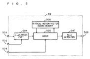
- Fig. 8 is a block diagram showing an essential configuration of the horizontal-block vertical-motion-vector calculating part 50.
- the horizontal-block vertical-motion-vector calculating part 50 includes three input terminals 501 to 503, an n-arization part 504, an adder 505 for adding the first horizontal-block projection data having been n-arized in the n-arization part 504, a vertical-motion-vector adding memory 506 as a buffer memory for successively storing data added by the adder 505, a peak detector 507, and an output terminal 508.
- the first horizontal-block projection data output from the horizontal-block projection-data reading part 49 is input to the input terminal 501.
- the fourth threshold value output from the second horizontal-block projection-data maximum-value storage part 47 is input to the input terminal 502. Further, the information on the third threshold intersection output from the third-threshold intersection searching part 48 is input to the input terminal 503.
- the n-arization part 504 n-arizes (e.g., ternarizes) the first horizontal-block projection data input through the input terminal 501 on the basis of the fourth threshold value input through the input terminal 502.
- the adder 505 adds the first horizontal-block projection data n-arized by the n-arization part 504 and the data read from the vertical-motion-vector adding memory 506 with the third threshold intersection placed at its center, and the result of addition is stored again in the vertical-motion-vector adding memory 506.
- added data for the horizontal blocks is output to the peak detector 507.
- the peak detector 507 detects the peak position (vertical motion vector which will be described later) and the peak value in the added data output from the adder 505. This peak position detected by the peak detector 507 is input to the vertical-motion-vector determining part 51 through the output terminal 508.
- the vertical image-dividing part 21 defines a plurality of image regions (vertical blocks) obtained by vertically dividing the frame image. In subsequent processes, processing and control is thereby carried out per vertical block.
- image data of 640 pixels, by 480 pixels as shown in, for example, (a) portion of Fig. 9 is divided into seven vertical blocks vb0 to vb6 having a width of 64 pixels (division width) in the vertical direction.
- Image data of the lowermost layer, vertical block vb7, in the vertical direction is not to be used in detection of a horizontal motion vector, but no particular problem arises in detection accuracy since seven vertical blocks vb0 to vb6 which occupy the most part of the frame image are used in detection of the horizontal motion vector.
- setting the division width and number of divisions as shown in (a) portion of Fig. 9 is not always necessary.
- the image divided into the seven vertical blocks vb0 to vb6 in the vertical image-dividing part 21 as shown in (a) portion of Fig. 9 is subjected to detection of an edge component extending in the vertical direction, in other words, a filtering process for enhancing an image portion abruptly changing in the horizontal direction, in the vertical-edge detection filtering part 22.
- a (1, -1) 2-tap filter for simply obtaining the difference from an adjacent pixel in the horizontal direction
- a (-1, 2, -1) 3-tap filter corresponding to a second derivative or the like can be employed.
- the use of such filter is not always necessary, and a filter that increases the output value in an image portion whose change in luminance increases in the horizontal direction will do.
- Image data whose vertical edge has been enhanced for each of the vertical blocks (image regions) vb0 to vb6 in the vertical-edge detection filtering part 22 is input to the vertical-block projecting part 23, and projected in the vertical direction by the vertical-block projecting part 23.
- a noise component (between lines) in the vertical direction can be reduced, and the vertical edge component can further be enhanced, so that the vertical edge corresponding to a characteristic point is made distinctive, which achieves improved motion-vector detection accuracy.
- the operation of the vertical-block projecting part 23 will be described with reference to the conceptual drawing shown in (b) portion of Fig. 9 .
- all arrayed elements are generated for each piece of vertical-block projection data vn0 to vn6 ((b) portion of Fig. 9 ) having a data array Mv for one horizontal line at the time when input of the respective vertical blocks vb0 to vb6 shown in (a) portion of Fig. 9 is completed, that is at the time when the last pixel on the last line in each of the edge-enhanced vertical blocks vb0 to vb6 is input.
- the data array Mv contains arrayed elements of the total pixel number of a horizontal line (e.g., 640), valid elements in a 2-tap filter such as (1, -1) is the total pixel number of the horizontal line minus 1 (e.g., 639), and valid elements in a 3-tap filter such as (-1, 2, -1) is the total pixel number of the horizontal line minus 2 (e.g., 638).
- a 2-tap filter such as (1, -1) is the total pixel number of the horizontal line minus 1 (e.g., 639)
- valid elements in a 3-tap filter such as (-1, 2, -1) is the total pixel number of the horizontal line minus 2 (e.g., 638).
- image data of the respective vertical blocks vb0 to vb6 (image data whose vertical edge has been enhanced) input through the input terminal 231 as shown in Fig. 4 is sequentially input to the adder 232.
- the adder 232 first, writes the leading horizontal line of the input vertical block into the vertical-projection temporary storage memory 233 without reading data within the vertical-projection temporary storage memory 233. Next, the adder 232 reads the result of addition up to the preceding line stored in the vertical-projection temporary storage memory 233, and carries out an addition with one horizontal line of the vertical block input through the input terminal 231, and writes back the result of addition into the vertical-projection temporary storage memory 233.
- the projection data obtained by adding all the horizontal lines of the vertical block may be once stored in the vertical-projection temporary storage memory 233, and when the leading line of the succeeding vertical block is input, the projection data within the vertical-projection temporary storage memory 233 may be read to be output through the output terminal 234.
- the first vertical-block projection-data maximum-value storage part 24 calculates the maximum value of the projection data output from the vertical-block projecting part 23, and stores it as the first vertical-block projection-data maximum value (current-frame vertical-block projection-data maximum value). That is, the first vertical-block projection-data maximum-value storage part 24 obtains the maximum value of arrayed elements of the data array Mv ((b) portion of Fig. 9 ) of the projection data of the current frame (succeeding frame), and stores this maximum value.
- the calculation of the second threshold value a2 is not limited to the above equation (1), but may be anything that makes the second threshold value ⁇ 2 larger as the current-frame vertical-block projection-data maximum value P1max increases, or alternatively, a conversion table may be used.
- the bit-number reducing part 25 determines a valid bit range of projection data on the basis of the current-frame vertical-block projection-data maximum value (first vertical-block projection-data maximum value) input from the first vertical-block projection-data maximum-value storage part 24. Then, higher-order invalid bits and lower-order invalid bits defined on the basis of this valid bit range are omitted from the vertical-block projection data input from the vertical-block projecting part 23, and the current-frame vertical-block projection data composed only of valid bits is output to the first vertical-block projection line memory 26.
- the first vertical-block projection line memory 26 stores the current-frame vertical-block projection data with the number of bits having been reduced by the bit-number reducing part 25, as the first vertical-block projection data, for each vertical block. That is, the projection data of the current frame (succeeding frame) with the number of bits (data length of each arrayed element) having been reduced by the bit-number reducing part 25 on the basis of the first vertical-block projection-data maximum value obtained in the first vertical-block projection-data maximum-value storage part 24 is stored in the first vertical-block projection line memory 26.
- the first vertical-block projection line memory 26 reads the preceding-frame vertical-block projection data at the time when a new piece of first vertical-block projection data of the current frame is input, and supplies it to the second vertical-block projection line memory 27.
- the second vertical-block projection line memory 27 stores the preceding-frame vertical-block projection data read from the first vertical-block projection line memory 26, as the second vertical-block projection data.
- the first vertical-block projection-data maximum-value storage part 24 reads the first vertical-block projection-data maximum value already stored at the time when the new first vertical-block projection-data maximum value of the current frame is updated, and supplies it to the second vertical-block projection-data maximum-value storage part 28.
- the second vertical-block projection-data maximum-value storage part 28 stores the first vertical-block projection-data maximum value read from the first vertical-block projection-data maximum-value storage part 24, as the second vertical-block projection-data maximum value of the preceding frame (preceding-frame vertical-block projection-data maximum value).
- the current-frame vertical-block projection-data maximum value stored in the first vertical-block projection-data maximum-value storage part 24 is to be stored as the preceding-frame vertical-block projection-data maximum value in the second vertical-block projection-data maximum-value storage part 28 in the succeeding frame.
- the calculation of the first threshold value ⁇ 1 is not limited to the above equation (2), but may be anything that makes the first threshold value ⁇ 1 larger as the preceding-frame vertical-block projection-data maximum value P2max increases, or alternatively, a conversion table may be used.
- the first-threshold intersection searching part 29 searches an intersection (first threshold intersection) of the second vertical-block projection data read from the second vertical-block projection line memory 27 and the first threshold value output from the second vertical-block projection-data maximum-value storage part 28, in the horizontal direction. Information on first threshold intersections obtained in this first-threshold intersection searching part 29 is output to the vertical-block projection-data reading part 30 and vertical-block horizontal-motion-vector calculating part 31.
- the motion vector detection range be (-V) to (+V) (where V is a positive integer) with the first threshold intersection placed at its center
- the projection data read from the first vertical-block projection line memory 26 is to be partial data of the first vertical-block projection data falling within the range of (A(i)-V) to (A(i)+V) in the horizontal direction.
- the first vertical-block projection data read from the first vertical-block projection line memory 26 by this vertical-block projection-data reading part 30 is output to the vertical-block horizontal-motion-vector calculating part 31.
- the first vertical-block projection data output from the vertical-block projection-data reading part 30 is input to the n-arization part 314 through the input terminal 311 of the vertical-block horizontal-motion-vector calculating part 31 shown in Fig. 5 .
- This n-arization part 314 n-arizes the first vertical-block projection data on the basis of the second threshold value output from the first vertical-block projection-data maximum-value storage part 24 and input through the input terminal 312. That is, the n-arization part 314 subjects the data length of each arrayed element of the data array Mv ((b) portion of Fig. 9 ) of the current-frame projection data extracted in the vertical-block projection-data reading part 30 to a ternarization process, for example, for compression. The process in this n-arization part 314 will be described with reference to Fig. 10 .
- Fig. 10 is a diagram for explaining an n-arization process in the n-arization part 314.
- the n-arization part 314 outputs (-1) when D ⁇ (- ⁇ 2), outputs 0 when (- ⁇ 2) ⁇ D ⁇ 2. and outputs 1 when D> ⁇ 2, thereby performing a ternarization process.
- ternarization is performed in three levels of: the case where the value of an arrayed element of the current-frame projection data extracted in the vertical-block projection-data reading part 30 is smaller than (- ⁇ 2); the case where it is not smaller than (- ⁇ 2) and not larger than a2; and the case where it is larger than ⁇ 2.
- the n-arization part 314 achieves improved motion-vector detection accuracy by subjecting the first vertical-block projection data to an appropriate n-arization process.
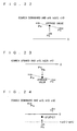
- Fig. 11 Operations of the above-explained first-threshold intersection searching part 29, vertical-block projection-data reading part 30 and vertical-block horizontal-motion-vector calculating part 31 will be specifically explained referring to Fig. 11 .
- the abscissa in (a) portion of Fig. 11 and (b) portion of Fig. 11 indicates the position of arrayed elements of the data array Mv ((b) portion of Fig. 9 ) of projection data.
- (a) portion of Fig. 11 indicates first threshold intersections A(1) to A(8) by circles, respectively.
- the first-threshold intersection searching part 29 obtains the first threshold intersections A(1) to A(8) which intersect the first threshold value ⁇ 1 output from the second vertical-block projection-data maximum-value storage part 28 in the waveform of the second vertical-block projection data W2 of the preceding frame, as shown in (a) portion of Fig. 11 . That is, the first-threshold intersection searching part 29 specifies the position of the arrayed elements of the respective first threshold intersections at which the waveform W2 obtained by graphing the values of the arrayed elements in the order of elements of the data array Mv ((b) portion of Fig. 9 ) of projection data relating to the projection data obtained in the vertical-block projecting part 23 for the preceding frame and the line on which the values of the arrayed elements stand at the first threshold value (predetermined constant value) ⁇ 1 intersect.
- the vertical-block projection-data reading part 30 reads the current-frame vertical-block projection data from the first vertical-block projection line memory 26 with respect to the predetermined motion vector detection range with the first threshold intersections A(1) to A(8) shown in (a) portion of Fig. 11 placed at its center. That is, the vertical-block projection-data reading part 30 extracts data arrays in the predetermined range with the position of arrayed elements of projection data (data array) in the respective first threshold intersections placed at its center, from the current-frame (succeeding-frame) projection data output from the vertical-block projecting part 23 with the number of bits having been reduced by the bit-number reducing part 25.
- first vertical-block projection data W1 corresponding to the range (the waveform portion within a rectangle indicated by broken lines) from (A(7)-V) to (A(7)+V) with the first threshold intersection A(7) as shown in (b) portion of Fig. 11 placed at its center is read.
- the first vertical-block projection data read by the vertical-block projection-data reading part 30 is subjected to the n-arization process in the n-arization part 314 of the vertical-block horizontal-motion-vector calculating part 31 using the second threshold value ⁇ 2 output from the first vertical-block projection-data maximum-value storage part 24.
- the first vertical-block projection data is subjected to the ternarization process as shown in (c) portion of Fig.
- the n-arization part 314 performs an n-arization process as shown in (c) portion of Fig. 11 for all the first threshold intersections output from the first-threshold intersection searching part 29.
- the adder 315 ( Fig. 5 ) adds the first vertical-block projection data n-arized by the n-arization pan 314 and the added values of the first vertical-block projection data n-arized up to the last one read from the horizontal-motion-vector adding memory 316 with the first threshold intersection output from the first-threshold intersection searching part 29 through the input terminal 313 placed at its center, and the result of addition is stored again in the horizontal-motion-vector adding memory 316.
- the first vertical-block projection data n-arized relating to the last one of all the first threshold intersections detected by the first-threshold intersection searching part 29 is added by the adder 315, and when the addition process for one vertical block is finished, the result of addition is to be output to the peak detector 317.
- the result of addition may be read by the peak detector 317 from the horizontal-motion-vector adding memory 316 which stores the results of addition for all the first threshold intersections.
- Data obtained by adding the first vertical-block projection data having been n-arized corresponding to the motion vector detection range (aforementioned range of ⁇ V) with each first threshold intersection placed at its center, to all the first threshold intersections detected by the first-threshold intersection searching part 29 (hereinafter also referred to as "vertical-block n-arized data") is input to the peak detector 317, and a peak value of this vertical-block n-arized data is detected by the peak detector 317.
- the peak position of the vertical-block n-arized data detected in the peak detector 317 is to be a horizontal motion vector obtained from that vertical block, and output to the horizontal-motion-vector determining part 32 through the output terminal 318.
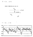
- FIG. 12 conceptually shows the first vertical-block projection data temarized in the motion vector detection range (range of ⁇ V) with the first threshold intersections A(1) to A(8) shown in (a) portion of Fig. 11 placed at its center.
- the adder 315 adds these pieces of data, and the vertical-block n-arized data as shown in (b) portion of Fig. 12 is generated. Specifically, the adder 315 adds values of arrayed elements having the same relative position with respect to the position of arrayed element of each first threshold intersection, for each data array in the motion vector detection range (predetermined range) of the current frame extracted by the vertical-block projection-data reading part 30 from the vertical-block projection data (data array Mv ((b) portion of Fig. 9 ) and compressed in data length in the n-arization part 314.
- the peak detector 317 detects the motion vector in the horizontal direction of a frame image on the basis of the result of addition added in the adder 315.
- the peak detector 317 basically searches a peak position in which the vertical-block n-arized data is to be its maximum value in the motion vector detection range (range of ⁇ V), but the peak with superiority may not sometimes appear for an image with periodicity, an image in which a subject has a motion and an unclear image. At this time, the reliability of the horizontal motion vector calculated from its vertical block is low, thereby to be determined as an invalid block, so that it should not be used for calculation of the horizontal motion vector of the entire image in the horizontal-motion-vector determining part 32.
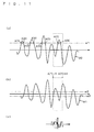
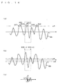
- FIG. 16 is a view corresponding to (b) portion of Fig. 12 , plotting a motion vector in abscissa and the vertical-block n-arized data in ordinate and showing one "crest" for descriptive purposes.
- Fig. 16 the respective vertical-block n-arized data at each relative position (horizontal motion vector) is marked with v1 to v10 in this order from the minus side.
- Data v1 is an "end of crest” of the previous crest, and also a “start of crest” which is searched from now on.
- the first "start of crest” is to be the vertical-block n-arized data of the horizontal motion vector residing at the utmost minus side (within range of -V to +V).
- the peak detector 317 sequentially shifts a relative position to be a comparison target for a relative position to be a reference position (horizontal motion vector) from the minus side to the plus side, and on each time, compares the size of the vertical-block n-arized data at both relative positions. In this case, the peak detector 317 changes the vertical-block n-arized data, which is determined to be larger by the comparison, to the reference value (or maintains as the reference value), and compares with a relative position to be a succeeding comparison target.
- the reference value is referred to as a provisional peak value Vp here.
- the horizontal motion vector exists further after data v10, but for setting a breakpoint here, the maximum value of the vertical-block n-arized data in one "crest" is defined as the maximum value Pn, and the horizontal motion vector having the vertical-block n-arized data smaller than the value which is set by multiplying the maximum value Pn by a predetermined coefficient is defined as a vector showing an "end of crest”.
- the predetermined coefficient to multiply the maximum value Pn is set as ⁇ (second coefficient satisfying 0 ⁇ 1), and data v10 is smaller than Vp ⁇ so that data v10 is defined as a vector showing an "end of crest" ("start of next crest").
- the predetermined coefficient ⁇ is empirically set as 1/2 or less, preferably within the range of 1/4 to 1 /8.
- the maximum value Pn peak value
- Vp provisional peak value
- one "crest” can be specified by defining the horizontal motion vector having the vertical-block n-arized data which is smaller than the value set by multiplying the maximum value Pn by a predetermined coefficient as a vector showing an "end of crest” ("start of next crest”).
- the above explanation shows the example to sequentially, shift the relative position to be a comparison target from the minus side to the plus side.
- the maximum value Pn may be obtained by sequentially shifting the relative position to be a comparison target from the plus side to the minus side.
- “Crest” may be treated as being of existence by simply defining the part in which the vertical-block n-arized data is shifted from increase to decrease as the maximum value Pn, but it is preferable to define an "end of crest" with the horizontal motion vector having the vertical-block n-arized data which is smaller than the value set by multiplying the maximum value Pn of the vertical-block n-arized data by a predetermined coefficient to capture the waveform as a whole.
- the maximum value Pn of the vertical-block n-arized data obtained for one "crest” is stored, and the similar process is carried out to the next "crest". "Crest” can be specified over the entire motion vector detection range, and the maximum value Pn (peak value) of the vertical-block n-arized data can be obtained, by repeating this operation.
- Fig. 17 shows the vertical-block n-arized data to each motion vector over the entire motion-vector detection range, and the waveform in which five "crests" of M1, M2, M3, M4 and M5 exist.
- the reliability is estimated by comparing the first peak value (P1st) and the second peak value (P2nd). Specifically, it is estimated by the following equation (3): P ⁇ 2 ⁇ nd > P ⁇ 1 ⁇ st ⁇ ⁇ where ⁇ is a previously-determined coefficient (first coefficient) satisfying 0 ⁇ 1.
- the result of calculation is to be determined as valid within a large range as much as possible even for the cases other than the ideal case where the image is clear and has no periodicity, and the subject is still, so that the result of calculation can be treated as valid, allowing certain degree of erroneous detection (misjudgment).
- the coefficient ⁇ may be constituted so that a user of a moving image taking device to which the present invention is applied may decide, or a manufacturer of the moving image taking device to which the present invention is applied may decide.
- the peak detector 317 treats the result of calculation as invalid when the maximum value of the peak value Pn of a "crest" is not larger than the previously-determined value, specifically when the peak value Pn is remarkably small to the total pixel number of a horizontal line.
- a small peak value Pn means less valid first threshold intersections.
- the previously-determined value in this process is, for example, set within the range less than 1/50 of the total pixel number of a horizontal line, and more realistically almost 1/100.
- the horizontal motion vectors (vectors at peak positions) calculated per vertical block in the peak detector 317 are input to the horizontal-motion-vector determining part 32 through the output terminal 318.
- the horizontal-motion-vector determining part 32 determines the horizontal motion vector of the entire image on the basis of the horizontal motion vectors of the respective vertical blocks sequentially output from the vertical-block horizontal-motion-vector calculating part 31. Specifically, a histogram is created to employ one with the greatest number of the vertical-block n-arized data.
- the peak detector 317 can estimate the reliability of the peak position (motion vector) to be the first peak value P1st by the large-and-small relation between the first peak value P1st and the second peak value P2nd, and as a result, vertical blocks having low reliability can be omitted so that the horizontal motion vector of the entire image can be determined on the basis of vertical blocks having high reliability.
- the horizontal image-dividing part 41 defines a plurality of image regions (horizontal blocks) obtained by horizontally dividing the frame image. In subsequent processes, processing and control is thereby carried out per horizontal block.
- image data of 640 pixels by 480 pixels as shown in, for example, (a) portion of Fig. 13 is divided into ten horizontal blocks hb0 to hb9 having a width of 64 pixels (division width) in the horizontal direction.
- setting the division width and number of divisions as shown in (a) portion of Fig. 13 is not always necessary.
- the image divided into the ten vertical blocks hb0 to hb9 in the horizontal image-dividing part 41 as shown in (a) portion of Fig. 13 is subjected to detection of an edge component extending in the horizontal direction, in other words, a filtering process for enhancing an image portion abruptly changing in the vertical direction, in the horizontal-edge detection filtering part 42.
- a (1, -1) 2-tap filter for simply obtaining the difference from an adjacent pixel in the vertical direction
- a (-1, 2, -1) 3-tap filter corresponding to a second derivative or the like can be employed.
- the use of such filter is not always necessary, and a filter that increases the output value in an image portion whose change in luminance increases in the vertical direction will do.
- one arrayed element of horizontal-block projection data hn0 to hn9 ((b) portion of Fig. 13 ) having a data array Mh for one vertical line is generated at the time when input of the respective horizontal blocks hb0 to hb9 shown in (a) portion of Fig. 13 is completed. Accordingly, all arrayed elements are completed at the time when input of the last horizontal line of the respective horizontal blocks hb0 to hb9 is completed.
- the data array Mh contains arrayed elements of the total pixel number of a vertical line (e.g., 480), valid elements in a 2-tap filter such as (1, -1) is the total pixel number of the vertical line minus 1 (e.g., 479), and valid elements in a 3-tap filter such as (-1,2,-1) is the total pixel number of the vertical line minus 2 (e.g., 478).
- a 2-tap filter such as (1, -1) is the total pixel number of the vertical line minus 1 (e.g., 479)
- valid elements in a 3-tap filter such as (-1,2,-1) is the total pixel number of the vertical line minus 2 (e.g., 478).
- image data of the respective horizontal blocks hb0 to hb9 (image data whose horizontal edge has been enhanced) input through the input terminal 431 as shown in Fig. 7 is input to the adder 432.
- the adder 432 first, writes the leading horizontal line of the input horizontal block into the horizontal-projection temporary storage memory 433 without reading data within the horizontal-projection temporary storage memory 433.
- the adder 432 reads the result of addition up to the preceding pixel of one horizontal line stored in the horizontal-projection temporary storage memory 433, and carries out an addition with the current pixel of one horizontal line of the horizontal block input through the input terminal 431, and writes back the result of addition into the horizontal-projection temporary storage memory 433.
- the adder 432 when the last pixel of one horizontal line in the horizontal block is input to the adder 432, the result of addition up to the preceding pixel stored in the horizontal-projection temporary storage memory 433 is read, and an addition with the last pixel of one horizontal line of the horizontal block input through the input terminal 431 is carried out, and the result of addition, that is, data obtained by adding all the pixels of one horizontal line of the horizontal block is output to the first horizontal-block projection line memory 44 and first horizontal-block projection-data maximum-value storage part 45 through the output terminal 434, as projection data for one horizontal line of the horizontal block.
- the projection data obtained by adding all the pixels of one horizontal line of the horizontal block may be once stored in the horizontal-projection temporary storage memory 433, and when the leading pixel of one horizontal line of the succeeding horizontal block is input, the projection data within the horizontal-projection temporary storage memory 433 may be read to be output through the output terminal 434.
- the first horizontal-block projection line memory 44 stores the current-frame horizontal-block projection data input from the horizontal-block projecting part 43 as the first horizontal-block projection data, per horizontal block.
- the first horizontal-block projection-data maximum-value storage part 45 calculates the maximum value of the horizontal-block projection data input from the horizontal-block projecting part 43 and stores it as the first horizontal-block projection-data maximum value (current-frame horizontal-block projection-data maximum value).
- the second horizontal-block projection line memory 46 stores the horizontal-block projection data read from the first horizontal-block projection line memory 44 as the second horizontal-block projection data of the preceding frame.
- the second horizontal-block projection-data maximum-value storage part 47 stores the first horizontal-block projection-data maximum value output from the first horizontal-block projection-data maximum-value storage part 45 as the second horizontal-block projection-data maximum value of the preceding frame (preceding-frame horizontal-block projection-data maximum value).
- the current-frame horizontal-block projection-data maximum value stored in the first horizontal-block projection-data maximum-value storage part 45 is to be stored in the second horizontal-block projection-data maximum-value storage part 47 in the succeeding frame as the preceding-frame horizontal-block projection-data maximum value.
- the second horizontal-block projection-data maximum-value storage part 47 calculates the fourth threshold value on the basis of the calculated preceding-frame horizontal-block projection-data maximum value. For instance, defining the preceding-frame horizontal-block projection-data maximum value as P4max, the fourth threshold value ⁇ 4 is calculated by the following equation (4):
- ⁇ ⁇ 4 P ⁇ 4 ⁇ max ⁇ k ⁇ 4 where k4 is a previously-determined coefficient satisfying 0 ⁇ k4 ⁇ 1.
- the calculation of the fourth threshold value ⁇ 4 is not limited to the above equation (4), but may be anything that makes the fourth threshold value ⁇ 4 larger as the preceding-frame horizontal-block projection-data maximum value P4max increases, or alternatively, a conversion table may be used. Further, it is not always necessary to use the second horizontal-block projection-data maximum value of each horizontal block for the fourth threshold value ⁇ 4, but the fourth threshold value may be calculated using the horizontal-block projection-data maximum value of the entire image of the preceding frame, and the same fourth threshold value may be employed for the entire image.
- the calculation of the third threshold value ⁇ 3 is not limited to the above equation (5), but may be anything that makes the third threshold value ⁇ 3 larger as the preceding-frame horizontal-block projection-data maximum value P3max increases, or alternatively, a conversion table may be used. Further, it is not always necessary to use the second horizontal-block projection-data maximum value of each horizontal block for the third threshold value ⁇ 3, but the third threshold value may be calculated using the horizontal-block projection-data maximum value of the entire image of the preceding frame, and the same third threshold value may be employed for the entire image.
- the third-threshold intersection searching part 48 searches an intersection (third threshold intersection) of the second horizontal-block projection data read from the second horizontal-block projection line memory 46 and the third threshold value output from the second horizontal-block projection-data maximum-value storage part 47, in the vertical direction. Information on this third threshold intersection obtained in this third-threshold intersection searching part 48 is input to the horizontal-block projection-data reading part 49 and horizontal-block vertical-motion-vector calculating part 50.
- the motion vector detection range be (-U) to (+U) (where U is a positive integer) with the third threshold intersection placed at its center
- the projection data read from the first horizontal-block projection line memory 44 is to be partial data of the first horizontal-block projection data falling within the range of (B(i)-U) to (B(i)+U) in the vertical direction.
- the first horizontal-block projection data read from the first horizontal-block projection line memory 44 by this horizontal-block projection-data reading part 49 is output to the horizontal-block vertical-motion-vector calculating part 50.
- the first horizontal-block projection data output from the horizontal-block projection-data reading part 49 is input to the n-arization part 504 through the input terminal 501 of the horizontal-block vertical-motion-vector calculating part 50 shown in Fig. 8 .
- This n-arization part 504 n-arizes the first horizontal-block projection data on the basis of the fourth threshold value output from the second horizontal-block projection-data maximum-value storage part 47 and input through the input terminal 502. That is, the n-arization part 504 compresses the data length of each arrayed element of the data array Mh ((b) portion of Fig. 13 ) of the current-frame projection data extracted in the horizontal-block projection-data reading part 49.
- the n-arization part 504 performs processing similar to the aforementioned n-arization part 314, where a ternarization process, for example, is executed. That is, in the ternarization process in the n-arization part 504, relating to the fourth threshold value ⁇ 4 ( ⁇ 4>0) defined on the basis of the maximum value of the arrayed elements of the data array Mh in the preceding-frame projection data, ternarization is performed in three levels of: the case where the value of an arrayed element of the current-frame projection data extracted in the horizontal-block projection-data reading part 49 is smaller than (- ⁇ 4); the case where it is not smaller than (- ⁇ 4) and not larger than ( ⁇ 4; and the case where it is larger than ⁇ 4. It is not absolutely necessary that the n-arization part 504 have the same characteristics as the n-arization part 314, but it may have different characteristics from the n-arization part 314.
- Fig. 14 Operations of the above-explained third-threshold intersection searching part 48, and horizontal-block projection-data reading part 49 and horizontal-block vertical-motion-vector calculating part 50 will be specifically explained referring to Fig. 14 .
- the abscissa in (a) portion of Fig. 14 and (b) indicates the position of arrayed elements of the data array Mh ((b) portion of Fig. 13 ) of projection data.
- (a) portion of Fig. 14 indicates third threshold intersections B(1) to B(6) by circles, respectively.
- the third-threshold intersection searching part 48 obtains the third threshold intersections B(i) to B(6) which intersect the third threshold value ⁇ 3 output from the second horizontal-block projection-data maximum-value storage part 47 in the waveform of second vertical-block projection data W4 of the preceding frame, as shown in (a) portion of Fig. 14 . That is, the third-threshold intersection searching part 48 specifies the position of the arrayed elements of the respective third threshold intersections at which the waveform W4 obtained by graphing the values of the arrayed elements in the order of elements of the data array Mh ((b) portion of Fig. 13 ) of projection data relating to the projection data obtained in the horizontal-block projecting part 43 for the preceding frame and the line on which the values of the arrayed elements stand at the third threshold value (predetermined constant value) ⁇ 3 intersect.
- the horizontal-block projection-data reading part 49 reads the current-frame horizontal-block projection data from the first horizontal-block projection line memory 44 with respect to the predetermined motion vector detection range with the third threshold intersections B(1) to B(6) shown in (a) portion of Fig. 14 placed at its center. That is, the horizontal-block projection-data reading part 49 extracts data arrays in the predetermined range with the position of arrayed elements of projection data (data array) in each third threshold intersection placed at its center, from the current-frame (succeeding-frame) projection data obtained from the horizontal-block projecting part 43.
- first horizontal-block projection data W3 corresponding to the range (the waveform portion within a rectangle indicated by broken lines) from (B(4)-U) to (B(4)+U) with the third threshold intersection B(4) as shown in (b) portion of Fig. 14 placed at its center is read.
- the first horizontal-block projection data read by the horizontal-block projection-data reading part 49 is subjected to the n-arization process in the n-arization part 504 of the horizontal-block vertical-motion-vector calculating part 50 using the fourth threshold value ⁇ 4 output from the second horizontal-block projection-data maximum-value storage part 47.
- the first horizontal-block projection data is subjected to the ternarization process as shown in (c) portion of Fig.
- the n-arization part 504 performs an n-arization process as shown in (c) portion of Fig. 14 for all the third threshold intersections output from the third-threshold intersection searching part 48.
- the adder 505 ( Fig. 8 ) adds the first horizontal-block projection data n-arized by the n-arization part 504 and the added values of the first horizontal-block projection data n-arized up to the last one read from the vertical-motion-vector adding memory 506 with the third threshold intersection output from the third-threshold intersection searching part 48 through the input terminal 503 placed at its center, and the result of addition is stored again in the vertical-motion-vector adding memory 506.
- the first horizontal-block projection data n-arized relating to the last one of all the third threshold intersections detected by the third-threshold intersection searching part 48 is added by the adder 505, and when the addition process for one horizontal block is finished, the result of addition is to be output to the peak detector 507.
- the result of addition may be read by the peak detector 507 from the vertical-motion-vector adding memory 506 which stores the results of addition for all the third threshold intersections.
- Horizontal-block n-arized data Data obtained by adding the first horizontal-block projection data having been n-arized corresponding to the motion vector detection range (aforementioned range of ⁇ U) with each third threshold intersection placed at its center, to all the third threshold intersections detected by the third-threshold intersection searching part 48 (hereinafter also referred to as "horizontal-block n-arized data") is input to the peak detector 507, and a peak value of this horizontal-block n-arized data is detected by the peak detector 507.
- the peak position of the horizontal-block n-arized data detected in the peak detector 507 is to be a vertical motion vector obtained from that horizontal block, and output to the vertical-motion-vector determining part 51 through the output terminal 508.
- FIG. 15 conceptually shows the first horizontal-block projection data temarized in the motion vector detection range (aforementioned range of ⁇ U) with the third threshold intersections B(1) to B(6) shown in (a) portion of Fig. 14 placed at its center.
- the adder 505 adds these pieces of data, and the horizontal-block n-arized data as shown in (b) portion of Fig. 15 is generated. Specifically, the adder 505 adds values of arrayed elements having the same relative position with respect to the position of arrayed element of each third threshold intersection, for each data array in the motion vector detection range (predetermined range) of the current frame extracted from the horizontal-block projection data (data array Mh ((b) portion of Fig. 13 )) by the horizontal-block projection-data reading part 49 and compressed in data length in the n-arization part 504.
- the peak detector 507 detects the motion vector in the vertical direction of a frame image on the basis of the result of addition added in the adder 505.
- the peak detector 507 basically searches a peak position in which the horizontal-block n-arized data is to be its maximum value in the motion vector detection range (range of ⁇ U), but the peak with superiority may not sometimes appear for an image with periodicity, an image in which a subject has a motion and an unclear image. At this time, the reliability of the vertical motion vector calculated from its horizontal block is low, thereby to be determined as an invalid block, so that it should not be used for calculation of the vertical motion vector of the entire image in the vertical-motion-vector determining part 51.
- Fig. 16 is a view corresponding to (b) portion of Fig. 15 , plotting a motion vector in abscissa and the horizontal-block n-arized data in ordinate and showing one "crest" for descriptive purposes.
- Fig. 16 the respective horizonatl-block n-arized data at each relative position (vertical motion vector) is marked with v1 to v10 in this order from the minus side.
- Data v1 is an "end of crest” of the previous crest, and also a “start of crest” which is searched from now on.
- the first "start of crest” is to be the horizontal-block n-arized data of the vertical motion vector residing at the utmost minus side (within range of-U to +U).
- the peak detector 507 sequentially shifts a relative position to be a comparison target for a relative position to be a reference position (vertical motion vector) from the minus side to the plus side, and on each time, compares the size of the horizontal-block n-arized data at both relative positions. In this case, the peak detector 507 changes the horizontal-block n-arized data, which is determined to be larger by the comparison, to the reference value (or maintains as the reference value), and compares with a relative position to be a succeeding comparison target.
- the reference value is referred to as a provisional peak value Vp here.
- the vertical motion vector exists further after data v10, but for setting a breakpoint here, the maximum value of the horizontal-block n-arized data in one "crest" is defined as the maximum value Pn, and the vertical motion vector having the horizontal-block n-arized data smaller than the value which is set by multiplying the maximum value Pn by a predetermined coefficient is defined as a vector showing an "end of crest”.
- the predetermined coefficient to multiply the maximum value Pn is set as ⁇ (0 ⁇ 1), and data v10 is smaller than Vp ⁇ so that data v10 is defined as a vector showing an "end of crest" ("start of next crest").
- the predetermined coefficient ⁇ is empirically set as 1/2 or less, preferably within the range of 1/4 to 1/8.
- the maximum value Pn peak value
- Vp provisional peak value
- one "crest” can be specified by defining the vertical motion vector having the horizontal-block n-arized data which is smaller than the value set by multiplying the maximum value Pn by a predetermined coefficient as a vector showing an "end of crest” ("start of next crest”).
- the above explanation shows the example to sequentially shift the relative position to be a comparison target from the minus side to the plus side.
- the maximum value Pn may be obtained by sequentially shifting the relative position to be a comparison target from the plus side to the minus side.
- “Crest” may be treated as being of existence by simply defining the part in which the horizontal-block n-arized data is shifted from increase to decrease as the maximum value Pn, but it is preferable to define an end of crest" with the vertical motion vector having the horizontal-block n-arized data which is smaller than the value set by multiplying the maximum value Pn of the horizontal-block n-arized data by a predetermined coefficient to capture the waveform as a whole.
- the maximum value Pn of the horizontal-block n-arized data obtained for one "crest” is stored, and the similar process is carried out to the next "crest". "Crest” can be specified over the entire motion-vector detection range, and the maximum value Pn (peak value) of the horizontal-block n-arized data can be obtained by repeating this operation.
- Fig. 17 shows the horizontal-block n-arized data to each motion vector over the entire motion-vector detection range, and the waveform in which five "crests" of M1, M2, M3, M4 and M5 exist.
- the motion vector corresponding thereto is to show the demanded horizontal-block motion, meaning high reliability of the calculated motion vector. Accordingly, the reliability is estimated by comparing the first peak value (P1st) and the second peak value (P2nd). Specifically, it is estimated by the aforementioned equation (3).
- the result of calculation is to be determined as valid within a large range as much as possible even for the cases other than the ideal case where the image is clear and has no periodicity, and the subject is still, so, that the result of calculation can be treated as valid, allowing certain degree of erroneous detection (misjudgment).
- the peak detector 507 treats the result of calculation as invalid when the maximum value of the peak value Pn of a "crest" is not larger than the previously-determined value, specifically when the peak value Pn is remarkably small to the total pixel number of a vertical line.
- a small peak value Pn means less valid third threshold intersections.
- the previously-determined value in this process is, for example, set within the range less than 1/50 of the total pixel number of a vertical line, and more realistically almost 1/100.
- the vertical motion vectors (vectors at peak positions) calculated per horizontal block in the peak detector 507 are input to the vertical-motion-vector determining part 51 through the output terminal 508.
- the vertical-motion-vector determining part 51 determines the vertical motion vector of the entire image on the basis of the vertical motion vectors of the respective horizontal blocks sequentially output from the horizontal-block vertical-motion-vector calculating part 50. Specifically, a histogram is created to adopt one with the greatest numbers of the horizontal-block n-arized data.
- the peak detector 507 can estimate the reliability of the peak position (motion vector) to be the first peak value P 1 st by the large-and-sinall relation between the first peak value P1st and the second peak value P2nd, and as a result, horizontal blocks having low reliability can be omitted so that the vertical motion vector of the entire image can be determined on the basis of horizontal blocks having high reliability.
- the peak detector 317 of the vertical-block horizontal-motion-vector calculating part 31 in the horizontal-motion-vector detecting section 2 of the motion-vector detection device 1 obtains the maximum value of the vertical-block n-arized data, making the maximum value as the first peak value (Plst), and estimates reliability of the horizontal motion vector obtained in the vertical block by the large-and-small relation with the second peak value (P2nd), thereby allowing to determine if it is valid or invalid.
- a vertical block having low reliability such as a block in which an image is unclear, and has periodicity, and a subject has a motion
- the horizontal-motion-vector determining part 32 which in turn allows a horizontal motion vector of the entire frame image to be determined on the basis of the result of the vertical block having high reliability.
- the first peak value (P1st) and the second peak value (P2nd) can be easily calculated by sequentially reading out the vertical-block n-arized data of each relative position and comparing them. Therefore the process can be performed even for short blanking period, thereby it is effective for real time process.
- the peak detector 507 of the horizontal-block vertical-motion-vector calculating part 50 in the vertical-motion-vector detecting section 4 of the motion-vector detection device 1 obtains the maximum value of the horizontal-block n-arized data, making the maximum value as the first peak value (P1st), and estimates the reliability of the vertical motion vector obtained in the horizontal block by the large-and-small relation with the second peak value (P2nd), thereby allowing to determine if it is valid or invalid.
- a horizontal block having low reliability such as a block in which an image is unclear, and has periodicity, and a subject has a motion
- the vertical-motion-vector determining part 51 which in turn allows a vertical motion vector of the entire frame image to be determined on the basis of the result of the horizontal block having high reliability.
- the first peak value (P1st) and the second peak value (P2nd) can be easily calculated by sequentially reading out the horizontal-block n-arized data of each relative position and comparing them. Therefore the process can be performed even for short blanking period, thereby it is effective for real time process.
- the motion-vector detection device 1 enhances the vertical edge of each divided image (vertical block) after dividing a frame image in the vertical direction by the vertical image-dividing part 21, a divided image whose vertical edge has been enhanced can be generated simply.
- each divided image (horizontal block) is enhanced after dividing a frame image in the horizontal direction by the horizontal image-dividing part 41, a divided image whose horizontal edge has been enhanced can be generated simply.
- a motion-vector detection device 1A according to a second embodiment of the present invention has a similar configuration to the motion-vector detection device 1 according to the first embodiment as shown in Fig. 1 , but is different in configuration of the horizontal motion vector detecting section and vertical motion vector detecting section.
- the configurations of a horizontal-motion-vector detecting section 2A and a vertical-motion-vector detecting section 4A in the motion-vector detection device 1 A will be described referring to Figs. 18 and 19 .
- Fig. 18 is a block diagram showing an essential configuration of the horizontal-motion-vector detecting section 2A.
- sections having similar functions as described in the first embodiment are indicated by the same characters.
- the vertical image-dividing part 21 and vertical-edge detection filtering part 22 are disposed in reverse order with respect to the horizontal-motion-vector detecting section 2 of the first embodiment.
- the operation of the horizontal-motion-vector detecting section 2A will be described hereinbelow.
- the vertical image-dividing part 21 defines a plurality of image regions (vertical blocks) obtained by vertically dividing the edge-enhanced frame image. In subsequent processes, processing and control is thereby carried out per vertical block.
- the image data divided in the vertical image-dividing part 21 is input to the vertical-block projecting part 23, and the process in the vertical-block projecting part 23 and subsequent processes are carried out similarly to the horizontal-motion-vector detecting section 2 of the first embodiment.
- Fig. 19 is a block diagram showing an essential configuration of the vertical-motion-vector detecting section 4A.
- sections having similar functions as described in the first embodiment are indicated by the same characters.
- the horizontal image-dividing part 41 and horizontal-edge detection filtering part 42 are disposed in reverse order with respect to the vertical-motion-vector detecting section 4 of the first embodiment.
- the operation of the vertical-motion-vector detecting section 4A will be described hereinbelow.
- the horizontal image-dividing part 41 defines a plurality of image regions (horizontal blocks) obtained by horizontally dividing the edge-enhanced frame image. In subsequent processes, processing and control is thereby carried out per horizontal block.
- the image data divided in the horizontal image-dividing part 41 is input to the horizontal-block projecting part 43, and the process in the horizontal-block projecting part 43 and subsequent processes are carried out similarly to the vertical-motion-vector detecting section 4 of the first embodiment.
- the motion-vector detection device 1A Similar effects to the first embodiment are achieved.
- the frame image is subjected to vertical edge enhancement in the vertical-edge detection filtering part 22, and then the edge-enhanced frame image is divided in the vertical direction in the vertical image-dividing part 21, so that a divided image whose vertical edge has been enhanced can be generated simply.
- the frame image is subjected to horizontal edge enhancement in the horizontal-edge detection filtering part 42, and then the edge-enhanced frame image is divided in the horizontal direction in the horizontal image-dividing part 41, so that a divided image whose horizontal edge has been enhanced can be generated simply.
- the motion-vector detection device 1A it is not essential to dispose the vertical-edge detection filtering part 22 and horizontal-edge detection filtering part 42 separately in the horizontal-motion-vector detecting section 2A and vertical-motion-vector detecting section 4A, respectively, but a horizontal/vertical-edge extraction filtering part which combines the functions of both the vertical-edge detection filtering part 22 and horizontal-edge detection filtering part 42 may be provided, and its output may be input to both the vertical image-dividing part 21 and horizontal image-dividing part 41.
- the vertical-edge detection filtering part and horizontal-edge detection filtering part in the above-described first and second embodiments may be configured to perform, for example, binarization: "with edge”; and “without edge” or ternarization: "with a positive edge”; "without edge”; and “with a negative edge” by threshold processing of judging the large-and-small relation with a predetermined threshold value after the filtering process on performing edge detection.
- threshold processing allows edges having luminance variations (luminance gradient) not less than the predetermined threshold to be handled identically.
- data output from the bit-number reducing part 25 may be input alternately to the first vertical-block projection line memory 26 and second vertical-block projection line memory 27 by switching per frame, for example.
- Data output from the horizontal-block projecting part 43 may be input alternately to the first horizontal-block projection line memory 44 and second horizontal-block projection line memory 46 by switching per frame, for example.
- data output from the vertical (horizontal)-block projecting part may be input alternately to the first vertical (horizontal)-block projection-data maximum-value storage part and second vertical (horizontal) block projection-data maximum-value storage part by switching per frame, for example.
- the "preceding frame" throughout the present invention involves not only the immediately preceding frame with respect to a succeeding frame (e.g.. current frame) but also second to the immediately preceding frame and more. For instance, in the case where an intermediate frame is skipped by frame skipping, a frame preceding to the skipped frame is involved.
- a motion-vector detection device 1B has similar configuration to the motion-vector detection device 1 according to the first embodiment, but is different in configuration of the horizontal motion vector detecting section and vertical motion vector detecting section.
- Fig. 20 is a block diagram showing an essential configuration of the horizontal-motion-vector detecting section 2B.
- sections having similar functions as the horizontal-motion-vector detecting section 2 described in the first embodiment are indicated by the same characters, and repeated description will be omitted.
- the horizontal-motion-vector detecting section 2B includes the input terminal 20, vertical image-dividing part 21, vertical-edge detection filtering part 22, vertical-block projecting part 23, first vertical-block projection-data maximum-value storage part 24, bit-number reducing part 25, first vertical-block projection line memory 26, and vertical-block projection-data smoothing part 34. Further, the horizontal-motion-vector detecting section 2B includes the second vertical-block projection line memory 27, second vertical-block projection-data maximum-value storage part 28, first-threshold intersection searching part 29, vertical-block projection-data reading part 30 vertical-block horizontal-motion-vector calculating part 31, horizontal-motion-vector determining part 32, and output terminal 33.
- the horizontal-motion-vector detecting section 2B is remarkably different in including the vertical-block projection-data smoothing part 34 from the horizontal-motion-vector detecting section 2 shown in Fig. 3 , and the operation of the vertical-block projection-data smoothing part 34 will be described in detail later.
- Fig. 21 is a block diagram showing an essential configuration of the vertical-motion-vector detecting section 4B.
- sections having similar functions as the vertical-motion-vector detecting section 4 described in the first embodiment are indicated by the same characters, and repeated description will be omitted.
- the vertical-motion-vector detecting section 4B includes an input terminal 40, a horizontal image-dividing part 41, a horizontal-edge detection filtering part 42, horizontal-block projecting part 43, a first horizontal-block projection line memory 44, a first horizontal-block projection-data maxinium-value storage part 45, and a horizontal-block projection-data smoothing part 53. Further, the vertical-motion-vector detecting section 4B includes a second horizontal-block projection line memory 46, a second horizontal-block projection-data maximum-value storage part 47, a third-threshold intersection searching part 48, a horizontal-block projection-data reading part 49, a horizontal-block vertical-motion-vector calculating part 50, a vertical-motion-vector determining part 51, and an output terminal 52.
- the verticai-motion-vector detecting section 4B is remarkably different in including the horizontal-block projection-data smoothing part 53 from the vertical-motion-vector detecting section 4 shown in Fig. 6 , and the operation of the horizontal-block projection-data smoothing part 53 will be described in detail later.
- each configuration of the horizontal-motion-vector detecting section 2B is basically similar to the operation of each configuration of the horizontal-motion-vector detecting section 2 shown in Fig. 3 except the vertical-block projection-data smoothing part 34, which are thus omitted to explain, and hereinbelow the operation of the vertical-block projection-data smoothing part 34 will be described.
- the smoothing process in the vertical-block projection-data smoothing part 34 will be explained in detail referring to Figs. 22 to 25 .
- the vertical block projection data stored in the first vertical-block projection line memory 26 is read by the vertical-block projection-data smoothing part 34, subjected to the smoothing process, and then written back to the first vertical-block projection line memory 26.
- Figs. 22 to 25 an example of performing the smoothing process using three successive arrayed elements of Pa, Pb and Pc in the horizontal direction will be explained.
- Each of a, b and c is a value at each point Pa, Pb and Pc.
- Fig. 22 shows the smoothing process where the fluctuation pattern of projection data is "convex downward, and a>0, b ⁇ 0, c>0".
- the pattern shown in Fig. 22 resolves the shape of being convex downward by changing the value b of the point Pb to the average value between the values a and c.
- Fig. 23 shows the smoothing process where the fluctuation pattern of projection data is "convex upward, and a ⁇ 0, b ⁇ 0, c ⁇ 0". Also in this case, the shape of being convex upward can be resolved by changing the value b of the center point Pb to the average value between the values a and c.
- Fig. 24 shows the smoothing process where the fluctuation pattern of projection data is "convex downward, and a>0, b ⁇ 0, c>0".
- the point Pa is considered to compose a part of the former fluctuation pattern constituted by the preceding points Pq, Pr...of the point Pa (... ⁇ Pr ⁇ Pq ⁇ Pa), and the point Pb is also considered to compose the former fluctuation pattern.
- the point Pc is considered to compose a part of the latter fluctuation pattern constituted by the succeeding points Ps, Pt...ofthe point Pc (Pc ⁇ Ps ⁇ Pt ⁇ ...), and the point Pb is also considered to compose the latter fluctuation pattern.
- the smoothing process is performed to change the value b of the point Pb to the value (- ⁇ ) which is compressed to "0" when being subjected to the n-arization process.
- the value which is compressed to "0" is referred to here as a value to be compressed, and the value to be compressed is set to be a fixed value lager than the second threshold value - ⁇ 2 and not larger than 0. This process allows characteristic of the preceding and the succeeding fluctuation patterns to be accurately reflected on the n-arization process without damaging characteristics of the both fluctuation patterns.
- Fig. 25 shows the smoothing process where the fluctuation pattern of projection data is "convex upward, and a ⁇ 0, b>0, c ⁇ 0".
- the point Pa is considered to compose a part of the former fluctuation pattern constituted by the preceding points Pq, Pr...of the point Pa (... ⁇ Pr ⁇ Pq ⁇ Pa), and the point Pb is also considered to compose the former fluctuation pattern.
- the point Pc is considered to compose a part of the latter fluctuation pattern constituted by the succeeding points Ps, Pt...of the point Pc (Pc ⁇ Ps ⁇ Pt ⁇ ...), and the point Pb is also considered to compose the latter fluctuation pattern.
- the smoothing process is performed to change the value b of the point Pb to the value ( ⁇ ) which is compressed to "0" when being subjected to the n-arization process.
- the value which is compressed to "0" is referred to here as a value to be compressed, and the value to be compressed is set to be a fixed value smaller than the second threshold value a2 and not smaller than 0. This process allows characteristics of the former and the latter fluctuation patterns to be accurately reflected on the n-arization process without damaging characteristics of the both fluctuation patterns.
- the value to be compressed In the case of setting the value to be compressed to 0, characteristic of the latter fluctuation pattern is slightly modified if the compressed value of the point Pb is used for smoothing the latter fluctuation pattern. However, if it is not a problem, the value to be compressed may be set to 0.
- Fig. 26 is assumed to be a part of the waveform of the vertical block projection data in the case of not performing the smoothing process. As shown in Fig. 26 , the waveform fluctuates up and down with adjacent each point.
- This fluctuation is considered to be caused by the process for various signals in the former circuit.
- the vertical direction for example, when a level of a signal subtly varies per line with a camera signal, such a subtle variation is considered to be prominent by being added (stressed) per projection process.
- Fig. 27 is a diagram schematically showing a state in which the threshold values a and - ⁇ to be subjected to the temarizatin process are set in the projection data shown in Fig. 26 , and the threshold values are found to go up and down at each point in circled regions. Accordingly, if the ternarization process is performed as they are in the above condition, the result of ternarization is heavily affected.
- Fig. 28 the result of performing the smoothing process described using Figs. 22 to 25 on the projection data shown in Fig. 26 is shown in Fig. 28 .
- Fig. 28 shows the waveform in which vibration superimposed on the original vertical block projection data is removed, remaining the overall characteristics of the waveform thereof.
- circled regions R11 to R15 are the regions obtained by smoothing data included in the regions with threshold values going up and down in Fig. 27 , and these circled regions are subjected to the smoothing process using the average value of both adjacent data, which is explained referring to Figs. 22 and 23 .
- the region R10 of Fig. 27 is a region having large fluctuation shown by the points 22, 23 and 24, in which the value of the point 23 is larger than the threshold value ⁇ , and the values of the points 22 and 24 are smaller than 0. These points are subjected to the smoothing process to change the value of the center point out of three points to a value to be compressed to "0" when being subjected to the n-arization process described referring to Figs. 24 and 25 .
- Fig. 29 is a diagram showing an example of vertical-block n-arized data added by the adder 315 in the motion vector detection range (aforementioned range of ⁇ V) with each first threshold intersection placed at its center, with respect to all the first threshold intersections detected in the first threshold intersection searching part 29, after the n-arization process of the first vertical-block projection data by the n-arization part 314.
- V is 31, and the scale 32 of abscissa shows the position of the horizontal motion vector 0.
- the maximum peak is located at the position of the scale 30 for both the waveforms "without the smoothing process” and "with the smoothing process", so that misjudgment does not happen when the peak detector 317 determines the maximum peak position of the entire motion vector detection range as the horizontal motion vector.
- the waveform "without the smoothing process" of the present embodiment is estimated as "not having the reliability", but the correct horizontal motion vector can be calculated in the waveform "with the smoothing process".
- blocks are formed at many positions including the positions of the scale 28 and 32 other than the position of the scale 30 on the waveform "without the smoothing process", each block having the added value of 40, 30 and 26.
- only one big peak should exist other than small peaks, so that the result cannot be trusted when there are similar big peak values at many positions as described above.
- the waveform "with the smoothing process” includes the added value of 21 at the scale 30, the added value of 5 at the scale 42 and the added value of 3 at the scale 5.
- the peak at the scale 30 can be determined to be only one big peak, so that the scale 30, that is, vector -2 can be determined to be the horizontal motion vector.
- the horizontal motion vector calculated per vertical block by the peak detector 317 is sequentially input to the horizontal-motion-vector determining part 32 through the output terminal 318.
- the horizontal-motion-vector determining part 32 determines the horizontal motion vector of the entire image on the basis of the horizontal motion vectors of the respective vertical blocks sequentially output from the vertical-block horizontal-motion-vector calculating part 31. Specifically, a histogram is created for the horizontal motion vector of the respective vertical blocks to determine the horizontal motion vector having the largest histogram value to be the horizontal motion vector of the entire image, or the like.
- each configuration of the vertical-motion-vector detecting section 4B is basically similar to the operation of each configuration of the vertical-motion-vector detecting section 4 shown in Fig. 6 except the horizontal-block projection-data smoothing part 53, which arc thus omitted to explain, and the operations of the horizontal-block projection-data smoothing part 53 will be described.
- the smoothing process in the horizontal-block projection-data smoothing part 53 will be explained in detail referring to Figs. 22 to 25 .
- the horizontal block projection data stored in the first horizontal-block projection line memory 44 is read by the horizontal-block projection-data smoothing part 53, subjected to the smoothing process, and then written back to the first horizontal-block projection line memory 44.
- Figs. 22 to 25 an example of performing the smoothing process using three successive arrayed elements of Pa, Pb and Pc in the vertical direction will be explained.
- Each of a, b and c is a value at each point Pa, Pb and Pc.
- Fig. 22 shows the smoothing process where the fluctuation pattern of projection data is "convex downward, and a>0, b ⁇ 0, c>0".
- the pattern shown in Fig. 22 resolves the shape of being convex downward by changing the value b of the point Pb to the average value between the values a and c.
- Fig. 23 shows the smoothing process where the fluctuation pattern of projection data is "convex upward, and a ⁇ 0, b ⁇ 0, c ⁇ 0". Also in this case, the shape of being convex upward can be resolved by changing the value b of the center point Pb to the average value between the values a and c.
- Fig. 24 shows the smoothing process where the fluctuation pattern of projection data is "convex downward, and a>0, b ⁇ 0, c>0".
- the point Pa is considered to compose a part of the former fluctuation pattern constituted by the preceding points Pq, Pr... of the point Pa (... ⁇ Pr ⁇ Pq ⁇ Pa), and the point Pb is also considered to compose the former fluctuation pattern.
- the point Pc is considered to compose a part of the latter fluctuation pattern constituted by the succeeding points Ps, Pt...of the point Pc (Pc ⁇ Ps ⁇ Pt ⁇ ...), and the point Pb is also considered to compose the latter fluctuation pattern.
- the smoothing process is performed to change the value b of the point Pb to the value (- ⁇ ) which is compressed to "0" when being subjected to the n-arization process.
- the value which is compressed to "0" is referred to here as a value to be compressed, and the value to be compressed is set to be a fixed value larger than the fourth threshold value - ⁇ 4 and not larger than 0. This process allows characteristics of the preceding and the succeeding fluctuation patterns to be accurately reflected on the n-arization process without damaging characteristics of the both fluctuation patterns.
- Fig. 25 shows the smoothing process where the fluctuation pattern of projection data is "convex upward, and a ⁇ 0, b>0, c ⁇ 0".
- the point Pa is considered to compose a part of the former fluctuation pattern constituted by the preceding points Pq, Pr...of the point Pa (... ⁇ Pr ⁇ Pq ⁇ Pa), and the point Pb is also considered to compose the former fluctuation pattern.
- the point Pc is considered to compose a part of the latter fluctuation pattern constituted by the succeeding points Ps, Pt...of the point Pc (Pc ⁇ Ps ⁇ Pt ⁇ ...), and the point Pb is also considered to compose the latter fluctuation pattern.
- the smoothing process is performed to change the value b of the point Pb to the value ( ⁇ ) which is compressed to "0" when being subjected to the n-arization process.
- the value which is compressed to "0" is referred to here as a value to be compressed, and the value to be compressed is set to be a fixed value smaller than the fourth threshold value ⁇ 4 and not smaller than 0. This process allows characteristics of the former and the latter fluctuation patterns to be accurately reflected on the n-arization process without damaging characteristics of the both fluctuation patterns.
- the value to be compressed In the case of setting the value to be compressed to 0, characteristic of the latter fluctuation pattern is slightly modified if the compressed value of the point Pb is used for smoothing the latter fluctuation pattern. However, if it is not a problem, the value to be compressed may be set to 0.
- Fig. 26 is assumed to be a part of the waveform of the horizontal block projection data in the case of not performing the smoothing process. As shown in Fig. 26 , the waveform fluctuates up and down with adjacent each point.
- This fluctuation is considered to be caused by the process for various signals in the former circuit.
- the horizontal direction for example, when a level of a signal subtly varies per line with a camera signal, such a subtle variation is considered to be prominent by being added (stressed) per projection process.
- Fig. 27 is a diagram schematically showing a state in which the threshold values ⁇ and - ⁇ to be subjected to the ternarizatin process are set in the projection data shown in Fig. 26 , and the threshold values are found to go up and down at each point in circled regions. Accordingly, if the ternarization process is performed as they are in the above condition, the result of ternarization is heavily affected.
- Fig. 28 the result of performing the smoothing process described using Figs. 22 to 25 on the projection data shown in Fig. 26 is shown in Fig. 28 .
- Fig. 28 shows the waveform in which vibration superimposed on the original vertical block projection data is removed, remaining the overall characteristics of the waveform thereof.
- circled regions R11 to R15 are the regions obtained by smoothing data included in the regions with threshold values going up and down in Fig. 27 , and these circled regions are subjected to the smoothing process using the average value of both adjacent data, which is explained referring to Figs. 22 and 23 .
- the region R10 of Fig. 27 is a region having large fluctuation shown by the points 22, 23 and 24, in which the value of the point 23 is larger than the threshold value ⁇ , and the values of the points 22 and 24 are smaller than 0. These points are subjected to the smoothing process to change the value of the center point out of three points to a value to be compressed to "0" when being subjected to the n-arization process described referring to Figs. 24 and 25 .
- Fig: 29 is a diagram showing an example of horizontal-block n-arized data added by the adder 505 in the motion vector detection range (aforementioned range of ⁇ U) with each third threshold intersection placed at its center, with respect to all the third threshold intersections detected in the third threshold intersection searching part 48, after the n-arization process of the first horizontal-block projection data by the n-arization part 504.
- U is 31, and the scale 32 of abscissa shows the position of the vertical motion vector 0.
- the maximum peak is located at the position of the scale 30 for both the waveforms "without the smoothing process” and "with the smoothing process", so that misjudgment does not happen when the peak detector 507 determines the maximum peak position of the entire motion vector detection range as the horizontal motion vector.
- the waveform "without the smoothing process" of the present embodiment is estimated as "not having the reliability", but the correct vertical motion vector can be calculated in the waveform "with the smoothing process".
- blocks are formed at many positions including the positions of the scale 28 and 32 other than the position of the scale 30 on the waveform "without the smoothing process", each block having the added value of 40, 30 and 26.
- only one big peak should exist other than small peaks, so that the result cannot be trusted when there are similar big peak values at many positions as described above.
- the waveform "with the smoothing process” includes the added value of 21 at the scale 30, the added value of 5 at the scale 42 and the added value of 3 at the scale 5.
- the peak at the scale 30 can be determined to be only one big peak, so that the scale 30, that is, vector -2 can be determined to be the vertical motion vector.
- the vertical motion vector calculated per horizontal block by the peak detector 507 is sequentially input to the vertical-motion-vector determining part 51 ( Fig. 21 ) through the output terminal 508.
- the vertical-motion-vector determining part 51 determines the vertical motion vector of the entire image on the basis of the vertical motion vectors of the respective horizontal blocks sequentially output from the horizontal-block vertical-motion-vector calculating part 50. Specifically, a histogram is created for the vertical motion vector of the respective horizontal blocks to determine the vertical motion vector having the largest histogram value to be the vertical motion vector of the entire image, or the like.
- superimposed local fluctuation noise can be removed in the vertical-block projection-data smoothing part 34 of the horizontal-motion-vector detecting section 2B of the motion-vector detection device 1B according to the third embodiment without damaging the broad tendency (characteristics) of the vertical block projection data, so that vertical-block horizontal motion vector having reliability can be detected.
- the horizontal motion vector of the entire image can be determined on the basis of the vertical-block horizontal motion vector having high reliability.
- superimposed local fluctuation noise can be removed in the horizontal-block projection-data smoothing part 53 of the vertical-motion-vector detecting section 4B without damaging the broad tendency (characteristics) of the horizontal block projection data, so that horizontal-block vertical motion vector having reliability can be detected.
- the vertical motion vector of the entire image can be determined on the basis of the horizontal-block vertical motion vector having high reliability.
- the bit-number reducing part 25 of the motion-vector detection device 1B reduces the number of bits of the current-frame vertical projection data on the basis of the current-frame vertical projection data obtained by the first vertical-block projection-data maximum-value storage part 24, the amount of calculations in the subsequent process can be suppressed, which permits more prompt detection of a motion vector.
- the motion-vector detection device 1B obtains the second vertical-block projection-data maximum value of the preceding frame and determines the first threshold value ⁇ 1 on the basis of this maximum value, an appropriate first threshold intersection can be determined. Similarly, since it obtains the second horizontal-block projection-data maximum value of the preceding frame and determines the third threshold value ⁇ 3 on the basis of this maximum value, an appropriate third threshold intersection can be determined.
- the motion-vector detection device 1B enhances the vertical edge of each divided image (vertical block) after dividing a frame image in the vertical direction by the vertical image-dividing part 21, a divided image whose vertical edge has been enhanced can be generated simply. Similarly, since it enhances the horizontal edge of each divided image (horizontal block) after dividing a frame image in the horizontal direction by the horizontal image-dividing part 41, a divided image whose horizontal edge has been enhanced can be generated simply.
- the motion-vector detection device 1B since projection data read by the vertical-block projection-data reading part 30 is n-arized in the n-arization part 314 of the vertical-block horizontal-motion-vector calculating part 31, the amount of subsequent calculations can be reduced, allowing motion vector detection to be performed more promptly.
- the n-arization part 314 performs ternarization on the basis of the second threshold value ⁇ 2 determined on the basis of the vertical-block projection-data maximum value of the current frame, motion vector detection capable of achieving real time processing while ensuring a relatively large dynamic range can be achieved. Further, the memory can be reduced significantly.
- the amount of subsequent calculations can be reduced, allowing motion vector detection to be performed more promptly.
- the n-arization part 504 performs ternarization on the basis of the fourth threshold value a4 determined on the basis of the horizontal-block projection-data maximum value of the preceding frame, motion vector detection capable of achieving real time processing without losing the dynamic range greatly can be achieved. Further, the memory can be reduced significantly.
- a motion-vector detection device 1C according to a fourth embodiment of the present invention has a similar configuration to the motion-vector detection device 1B according to the third embodiment shown in Fig. 20 , but is different in configuration of the horizontal-motion-vector detecting section and vertical-motion-vector detecting section.
- the configurations of a horizontal-motion-vector detecting section 2C and a vertical-motion-vector detecting section 4C in the motion-vector detection device 1C will be described below referring to Figs. 30 and 31 .
- Fig. 30 is a block diagram showing an essential configuration of the horizontal-motion-vector detecting section 2C.
- sections having similar functions described in the third embodiment are indicated by the same characters.
- the vertical image-dividing part 21 and vertical-edge detection filtering part 22 are disposed in reverse order with respect to the horizontal-motion-vector detecting section 2B of the third embodiment. The operation of this horizontal-motion-vector detecting section 2C will be described below.
- the vertical image-dividing part 21 defines a plurality of image regions (vertical blocks) obtained by vertically dividing the edge-enhanced frame image. In subsequent processes, processing and control is thereby carried out per vertical block.
- the image data divided in the vertical image-dividing part 21 is input to the vertical-block projecting part 23, and the process in the vertical-block projecting part 23 and subsequent processes are carried out similarly to the horizontal-motion-vector detecting section 2B of the third embodiment.
- Fig. 31 is a block diagram showing an essential configuration of the vertical-motion-vector detecting section 4C.
- sections having similar functions as the third embodiment are indicated by the same characters.
- the horizontal image-dividing part 41 and horizontal-edge detection filtering part 42 are disposed in reverse order with respect to the vertical-motion-vector detecting section 4B of the third embodiment.
- the operation of the vertical-motion-vector detecting section 4C will be described below.
- the horizontal image-dividing part 41 defines a plurality of image regions (horizontal blocks) obtained by horizontally dividing the edge-enhanced frame image. In subsequent processes, processing and control is thereby carried out per horizontal block.
- the image data divided in the horizontal image-dividing part 41 is input to the horizontal-block projecting part 43, and the process in the horizontal-block projecting part 43 and subsequent processes are carried out similarly to the vertical-motion-vector detecting section 4B of the third embodiment.
- the frame image is subjected to vertical edge enhancement in the vertical-edge detection filtering part 22, and then the edge-enhanced frame image is divided in the vertical direction in the vertical image-dividing part 21, so that a divided image whose vertical edge has been enhanced can be generated simply.
- the frame image is subjected to horizontal edge enhancement in the horizontal-edge detection filtering part 42, and then the edge-enhanced frame image is divided in the horizontal direction in the horizontal image-dividing part 41, so that a divided image whose horizontal edge has been enhanced can be generated simply.
- the motion-vector detection device IC it is not essential to dispose the vertical-edge detection filtering part 22 and horizontal-edge detection filtering part 42 separately in the horizontal-motion-vector detecting section 2C and vertical-motion-vector detecting section 4C, respectively, but a horizontal/vertical-edge extraction filtering part which combines the functions of both the vertical-edge detection filtering part 22 and horizontal-edge detection filtering part 42 may be provided, and its output may be input to both the vertical image-dividing part 21 and horizontal image-dividing part 41.
- the vertical-edge detection filtering part and horizontal-edge detection filtering part in the above-described third and fourth embodiments may be configured to perform, for example, binarization: "with edge”; and “without edge” or ternarization: "with a positive edge”; "without edge”; and “with a negative edge” by threshold processing of judging the large-and-small relation with a predetermined threshold value after the filtering process of performing edge detection.
- threshold processing allows edges having luminance variations (luminance gradient) not less than the predetermined threshold to be handled identically.
- data output from the bit-number reducing part 25 may be input alternately to the first vertical-block projection line memory 26 and second vertical-block projection line memory 27 by switching per frame, for example.
- Data output from the horizontal-block projecting part 43 may be input alternately to the first horizontal-block projection line memory 44 and second horizontal-block projection line memory 46 by switching per frame, for example.
- data output from the vertical (horizontal)-block projecting part may be input alternately to the first vertical (horizontal)-block projection-data maximum-value storage part and second vertical (horizontal-block projection-data maximum-value storage part by switching per frame, for example.
- the "preceding frame" throughout the present invention involves not only the immediately preceding frame with respect to a succeeding frame (e.g., current frame) but also second to the immediately preceding frame and more. For instance, in the case where an intermediate frame is skipped by frame skipping, a frame preceding to the skipped frame is involved.
Claims (13)
- Dispositif de détection de vecteur de mouvement destiné à détecter un vecteur de mouvement entre des images de trame d'une trame précédente et d'une trame suivante adjacentes l'une à l'autre dans une séquence temporelle, comprenant :un moyen d'amélioration de bord (22) pour améliorer un bord vertical d'un bloc vertical prédéterminé dans ladite image de trame lue en répétant de manière séquentielle un balayage des pixels des lignes horizontales dans la direction verticale ;un moyen de projection (23) pour obtenir une projection verticale obtenue en ajoutant toutes les lignes horizontales du bloc vertical dont les bords ont été améliorés par ledit moyen d'amélioration de bord (22), générant de ce fait des données de projection présentant un réseau de données pour une ligne horizontale ;un moyen de spécification (29) pour spécifier la position d'un élément en réseau de chaque intersection au niveau de laquelle se croisent une forme d'onde obtenue en mettant en graphique les valeurs des éléments en réseau dans l'ordre des éléments dudit réseau de données des données de projection obtenues dans ledit moyen de projection pour ladite trame précédente, et une ligne sur laquelle les valeurs des éléments en réseau indiquent une valeur constante prédéterminée ; caractérisé en ce qu'il comprendun moyen d'extraction (30) pour extraire des réseaux de données d'une plage prédéterminée, la position de l'élément en réseau de chaque dite intersection étant placée en son centre, à partir des données de projection obtenues par ledit moyen de projection (23) de ladite trame suivante ;un moyen de sommation (31) pour sommer les valeurs des éléments en réseau présentant la même position relative par rapport à la position de l'élément en réseau de chaque dite intersection pour chacun des réseaux de données de plage prédéterminée extraits par ledit moyen d'extraction (30) ; etun moyen de détection (32) pour détecter un vecteur de mouvement horizontal d'un bloc vertical prédéterminé de ladite image de trame sur la base du résultat de sommation obtenu par ledit moyen de sommation (31), dans lequel ledit moyen de détection (32) estime la fiabilité dudit vecteur de mouvement horizontal obtenu par rapport audit bloc vertical prédéterminé de ladite image de trame sur la base dudit résultat de sommation au niveau de chaque position relative obtenu par ledit moyen de sommation (31) ;dans lequel :ledit moyen de détection (32) obtient la valeur maximale dudit résultat de sommation en comparant de manière relative ledit résultat de sommation desdits éléments en réseau présentant la même position relative, obtenu par ledit moyen de sommation (31), et estime la fiabilité dudit vecteur de mouvement horizontal obtenu par rapport audit bloc vertical prédéterminé de ladite image de trame sur la base de ladite valeur maximale dudit résultat de sommation ; etdans lequel :ledit moyen de détection (32) spécifie une crête d'une forme d'onde obtenue en mettant en graphique ledit résultat de sommation desdits éléments en réseau présentant la même position relative par rapport à ladite position relative, dans le cas où il y a plusieurs crêtes, compare de manière relative ledit résultat de sommation afin de spécifier si le résultat de sommation est une pointe de chaque dite crête à partir dudit résultat de sommation constituant chaque dite crête en tant que valeur de pointe de chaque dite crête, désignant une valeur maximale en tant que première valeur de pointe à partir d'une pluralité des dites valeurs de pointe ainsi que la valeur maximale suivante en tant que deuxième valeur de pointe, et ledit moyen de détection (32) compare ladite première valeur de pointe et ladite deuxième valeur de pointe, et dans le cas où la proportion de ladite première valeur de pointe par rapport à ladite deuxième valeur de pointe n'est pas supérieure à une valeur prédéterminée, traite ledit vecteur de mouvement horizontal obtenu par rapport audit bloc vertical prédéterminé de ladite image de trame comme étant non valide.
- Dispositif de détection de vecteur de mouvement selon la revendication 1, dans lequel :dans le cas où ladite valeur maximale dudit résultat de sommation n'est pas supérieure à une valeur prédéterminée déterminée précédemment, ledit moyen de détection (32) traite ledit vecteur de mouvement horizontal obtenu par rapport audit bloc vertical prédéterminé de ladite image de trame comme étant non valide.
- Dispositif de détection de vecteur de mouvement destiné à détecter un vecteur de mouvement entre des images de trame d'une trame précédente et d'une trame suivante adjacentes l'une à l'autre dans une séquence temporelle, comprenant :un moyen d'amélioration de bord (42) pour améliorer un bord horizontal d'un bloc horizontal prédéterminé dans ladite image de trame lue en répétant de manière séquentielle un balayage des pixels des lignes horizontales dans la direction verticale ;un moyen de projection (43) pour obtenir une projection horizontale de l'image dont le bord a été amélioré par ledit moyen d'amélioration de bord (42), générant de ce fait des données de projection présentant un réseau de données pour une ligne verticale ;un moyen de spécification (48) pour spécifier la position d'un élément en réseau de chaque intersection au niveau de laquelle se croisent une forme d'onde obtenue en mettant en graphique les valeurs des éléments en réseau dans l'ordre des éléments dudit réseau de données des données de projection obtenues dans ledit moyen de projection (43) pour ladite trame précédente, et une ligne sur laquelle les valeurs des éléments en réseau indiquent une valeur constante prédéterminée ; caractérisé en ce qu'il comprend :un moyen d'extraction (49) pour extraire des réseaux de données d'une plage prédéterminée, la position de l'élément en réseau de chaque dite intersection étant placée en son centre, à partir des données de projection obtenues par ledit moyen de projection de ladite trame suivante ;un moyen de sommation (50) pour sommer les valeurs des éléments en réseau présentant la même position relative par rapport à la position de l'élément en réseau de chaque dite intersection pour chacun des réseaux de données de la plage prédéterminée extraits par ledit moyen d'extraction (49) ; etun moyen de détection (51) pour détecter un vecteur de mouvement vertical d'un bloc horizontal prédéterminé de ladite image de trame sur la base du résultat de sommation obtenu par ledit moyen de sommation (50), dans lequel
ledit moyen de détection (51) estime la fiabilité dudit vecteur de mouvement vertical obtenu par rapport audit bloc horizontal prédéterminé de ladite image de trame sur la base dudit résultat de sommation au niveau de chaque position relative obtenu par ledit moyen de sommation (50), dans lequel :ledit moyen de détection (51) obtient la valeur maximale dudit résultat de sommation en comparant de manière relative ledit résultat de sommation desdits éléments en réseau présentant la même position relative, obtenu par ledit moyen de sommation (50), et estime la fiabilité dudit vecteur de mouvement vertical obtenu par rapport audit bloc horizontal prédéterminé de ladite image de trame sur la base de ladite valeur maximale dudit résultat de sommation, et dans lequel :ledit moyen de détection (51) spécifie une crête d'une forme d'onde obtenue en mettant en graphique ledit résultat de sommation desdits éléments en réseau présentant la même position relative par rapport à ladite position relative, dans le cas où il y a plusieurs crêtes, compare de manière relative ledit résultat de sommation afin de spécifier si le résultat de sommation est une pointe de chaque dite crête à partir dudit résultat de sommation constituant chaque dite crête en tant que valeur de pointe de chaque dite crête, désignant une valeur maximale en tant que première valeur de pointe à partir d'une pluralité des dites valeurs de pointe ainsi que la valeur maximale suivante en tant que deuxième valeur de pointe, et ledit moyen de détection (32) compare ladite première valeur de pointe et ladite deuxième valeur de pointe, et dans le cas où la proportion de ladite première valeur de pointe par rapport à ladite deuxième valeur de pointe n'est pas supérieure à une valeur prédéterminée, traite ledit vecteur de mouvement vertical obtenu par rapport au bloc horizontal prédéterminé de ladite image de trame comme étant non valide. - Dispositif de détection de vecteur de mouvement selon la revendication 3, dans lequel
dans le cas où ladite valeur maximale dudit résultat de sommation n'est pas supérieure à une valeur prédéterminée déterminée précédemment, ledit moyen de détection (51) traite ledit vecteur de mouvement vertical obtenu par rapport audit bloc horizontal prédéterminé de ladite image de trame comme étant non valide. - Dispositif de détection de vecteur de mouvement selon la revendication 1 ou 3, dans lequel
ledit moyen de détection (51) détermine une position relative en tant que valeur de référence par rapport à ladite forme d'onde obtenue en mettant en graphique ledit résultat de sommation par rapport à ladite position relative, décale de manière séquentielle ladite position relative pour qu'elle devienne une cible de comparaison afin que la position relative soit une valeur de référence, et dans le cas où l'on constate que ledit résultat de sommation, qui est supérieur audit résultat de sommation au niveau de ladite position relative, est une valeur de référence, obtient ladite valeur de pointe de chaque dite crête en répétant un processus visant à remplacer ladite valeur de référence par ladite position relative pour devenir ladite cible de comparaison. - Dispositif de détection de vecteur de mouvement selon la revendication 5, dans lequel :dans le cas où ledit résultat de sommation au niveau de ladite position relative comme étant ladite cible de comparaison pour ladite valeur de pointe de chaque dite crête, est une valeur inférieure à une valeur obtenue en multipliant ladite valeur de pointe par un deuxième coefficient déterminé précédemment, ledit moyen de détection (51) spécifie ladite crête en définissant ladite position relative comme étant ladite cible de comparaison parmi une pluralité de dites crêtes comme étant une extrémité d'une crête et en la définissant aussi comme étant le début d'une crête suivante.
- Dispositif de détection de vecteur de mouvement selon la revendication 1, caractérisé en ce qu'il comprend
un moyen de lissage (34) pour obtenir une donnée de projection lissée en éliminant le bruit fluctuant superposé à ladite donnée de projection, dans lequel
un moyen de spécification (29) pour spécifier la position d'un élément en réseau de chaque intersection au niveau de laquelle se croisent une forme d'onde obtenue en mettant en graphique les valeurs des éléments en réseau dans l'ordre des éléments dudit réseau de données de ladite donnée de projection lissée pour ladite trame précédente, et une ligne sur laquelle les valeurs des éléments en réseau indiquent une valeur constante prédéterminée ; et
un moyen d'extraction (30) pour extraire des réseaux de données d'une plage prédéterminée, la position de l'élément en réseau de chaque dite intersection étant placée en son centre, à partir de ladite donnée de projection lissée pour ladite trame suivante ; dans lequel
lesdits moyens de lissage (34, 53) exécutent un processus de lissage sur la base de trois éléments en réseau successifs par rapport à une forme d'onde obtenue en mettant en graphique les valeurs des éléments en réseau dans l'ordre des éléments dudit réseau de données de ladite donnée de projection ; et
ledit processus de lissage comprend un processus consistant à remplacer la valeur du centre des éléments en réseau par une valeur moyenne située entre les éléments en réseau précédents et suivants dans le cas où chacun desdits trois éléments en réseau est une valeur positive et forme un motif convexe vers le bas, et un processus consistant à remplacer ladite valeur du centre des éléments en réseau par ladite valeur moyenne située entre lesdits éléments en réseau précédents et suivants dans le cas où chacun desdits trois éléments en réseau est une valeur négative et forme un motif convexe vers le haut. - Dispositif de détection de vecteur de mouvement selon la revendication 3, caractérisé en ce qu'il comprend
un moyen de lissage (53) pour obtenir une donnée de projection lissée en éliminant le bruit fluctuant superposé à ladite donnée de projection, dans lequel
le moyen de spécification (43) pour spécifier la position d'un élément en réseau de chaque intersection au niveau de laquelle se croisent une forme d'onde obtenue en mettant en graphique les valeurs des éléments en réseau dans l'ordre des éléments dudit réseau de données de ladite donnée de projection lissée pour ladite trame précédente, et une ligne sur laquelle les valeurs des éléments en réseau indiquent une valeur constante prédéterminée ; et
le moyen d'extraction (49) pour extraire des réseaux de données d'une plage prédéterminée, la position de l'élément en réseau de chaque dite intersection étant placée en son centre, à partir de ladite donnée de projection lissée pour ladite trame suivante, dans lequel
lesdits moyens de lissage (34, 53) exécutent un processus de lissage sur la base de trois éléments en réseau successifs par rapport à une forme d'onde obtenue en mettant en graphique les valeurs des éléments en réseau dans l'ordre des éléments dudit réseau de données de ladite donnée de projection ; et
ledit processus de lissage comprend un processus consistant à remplacer la valeur du centre des éléments en réseau par une valeur moyenne située entre les éléments en réseau précédents et suivants dans le cas où chacun desdits trois éléments en réseau est une valeur positive et forme un motif convexe vers le bas, et un processus consistant à remplacer ladite valeur du centre des éléments en réseau par ladite valeur moyenne située entre lesdits éléments en réseau précédents et suivants dans le cas où chacun desdits trois éléments en réseau est une valeur négative et forme un motif convexe vers le haut. - Dispositif de détection de vecteur de mouvement selon la revendication 7 ou 8, comprenant en outre :un moyen de spécification de valeur maximale (28) pour obtenir la valeur maximale des éléments en réseau des données de projection par rapport à ladite trame précédente, dans lequelladite valeur constante prédéterminée est fixée sur la base de la valeur maximale obtenue par ledit moyen de spécification de valeur maximale (28).
- Dispositif de détection de vecteur de mouvement selon la revendication 7 ou 8, comprenant en outre :des moyens de compression (314, 504) pour compresser la longueur des données de chaque élément en réseau des réseaux de données de la plage prédéterminée extraits par lesdits moyens d'extraction (30, 49), et dans lequellesdits moyens de sommation (31, 50) comprennent des moyens (315, 505) pour sommer les valeurs des éléments en réseau présentant la même position relative par rapport à la position de l'élément en réseau de chaque dite intersection pour chaque réseau de données de la plage prédéterminée dont la longueur des données a été compressée par lesdits moyens de compression (314, 504).
- Dispositif de détection de vecteur de mouvement selon la revendication 10, dans lequel
lesdits moyens de compression (314, 504) soumettent la valeur de chaque élément en réseau des réseaux de données de la plage prédéterminée extrait par lesdits moyens d'extraction (30, 49), à un processus de temarisation : et
dans ledit processus de ternarisation, en ce qui concerne une valeur de seuil Th (Th > 0) définie sur la base de la valeur maximale des éléments en réseau de la donnée de projection de ladite trame suivante, ou de la donnée de projection de ladite trame précédente, une ternarisation est exécutée à trois niveaux : dans le cas où la valeur d'un élément en réseau de la donnée de projection extrait par lesdits moyens d'extraction est inférieure à (- Th) ; dans le cas où elle n'est pas inférieure à (- Th) et n'est pas supérieure à Th ; et dans le cas où elle est supérieure à Th. - Dispositif de détection de vecteur de mouvement selon la revendication 7 ou 8, dans lequel
ledit processus de lissage comprend un processus consistant à remplacer la valeur du centre des éléments en réseau par une valeur moyenne située entre les éléments en réseau précédents et suivants dans le cas où lesdits trois éléments en réseau sont des valeurs positive, nulle et positive, et forment un motif convexe vers le bas, et un traitement consistant à remplacer ladite valeur du centre des éléments en réseau par ladite valeur moyenne située entre lesdits éléments en réseau précédents et suivants dans le cas où lesdits trois éléments en réseau sont une valeur négative, nulle et négative, et forment un motif convexe vers le haut. - Dispositif de détection de vecteur de mouvement selon la revendication 7 ou 8, dans lequel :lesdits moyens de lissage (34, 53) exécutent un processus de lissage sur la base de trois éléments en réseau successifs par rapport à une forme d'onde obtenue en mettant en graphique les valeurs des éléments en réseau dans l'ordre des éléments dudit réseau de données de ladite donnée de projection ; etledit processus de lissage comprend un processus consistant à remplacer la valeur du centre des éléments en réseau par une valeur compressée à zéro dans lesdits moyens de compression dans le cas où lesdits trois éléments en réseau sont des valeurs positive, négative et positive, et forment un motif convexe vers le bas, et un processus consistant à remplacer ladite valeur du centre des éléments en réseau par la valeur compressée à zéro dans lesdits moyens de compression dans le cas où lesdits trois éléments en réseau sont des valeurs négative, positive et négative, et forment un motif convexe vers le haut.
Applications Claiming Priority (3)
| Application Number | Priority Date | Filing Date | Title |
|---|---|---|---|
| JP2006323056A JP4083782B1 (ja) | 2006-11-30 | 2006-11-30 | 動きベクトル検出装置 |
| JP2007009732A JP4313820B2 (ja) | 2007-01-19 | 2007-01-19 | 動きベクトル検出装置 |
| PCT/JP2007/061723 WO2008065764A1 (fr) | 2006-11-30 | 2007-06-11 | Dispositif de détection de vecteur de mouvement |
Publications (3)
| Publication Number | Publication Date |
|---|---|
| EP2088558A1 EP2088558A1 (fr) | 2009-08-12 |
| EP2088558A4 EP2088558A4 (fr) | 2011-08-31 |
| EP2088558B1 true EP2088558B1 (fr) | 2013-03-27 |
Family
ID=39467564
Family Applications (1)
| Application Number | Title | Priority Date | Filing Date |
|---|---|---|---|
| EP07745013A Not-in-force EP2088558B1 (fr) | 2006-11-30 | 2007-06-11 | Dispositif de détection de vecteur de mouvement |
Country Status (2)
| Country | Link |
|---|---|
| EP (1) | EP2088558B1 (fr) |
| WO (1) | WO2008065764A1 (fr) |
Family Cites Families (8)
| Publication number | Priority date | Publication date | Assignee | Title |
|---|---|---|---|---|
| JP3164121B2 (ja) | 1992-02-21 | 2001-05-08 | キヤノン株式会社 | 動きベクトル検出装置 |
| JP3314556B2 (ja) | 1994-10-28 | 2002-08-12 | 松下電器産業株式会社 | 画像表示装置 |
| JP3930935B2 (ja) | 1997-02-28 | 2007-06-13 | 三菱電機株式会社 | 画像処理装置 |
| JP4652536B2 (ja) | 2000-08-21 | 2011-03-16 | 三菱電機株式会社 | 動き情報検知装置及び動き情報検知方法及び動き情報検知プログラムを記録した記録媒体 |
| JP2002279430A (ja) * | 2001-03-14 | 2002-09-27 | Lg Electronics Inc | 動きベクトル検出回路 |
| JP2004343483A (ja) * | 2003-05-16 | 2004-12-02 | Acutelogic Corp | 手振れ補正装置および方法、手振れ検出装置 |
| US7212651B2 (en) * | 2003-06-17 | 2007-05-01 | Mitsubishi Electric Research Laboratories, Inc. | Detecting pedestrians using patterns of motion and appearance in videos |
| JP3862728B2 (ja) * | 2005-03-24 | 2006-12-27 | 三菱電機株式会社 | 画像動きベクトル検出装置 |
-
2007
- 2007-06-11 EP EP07745013A patent/EP2088558B1/fr not_active Not-in-force
- 2007-06-11 WO PCT/JP2007/061723 patent/WO2008065764A1/fr active Application Filing
Also Published As
| Publication number | Publication date |
|---|---|
| EP2088558A1 (fr) | 2009-08-12 |
| WO2008065764A1 (fr) | 2008-06-05 |
| EP2088558A4 (fr) | 2011-08-31 |
Similar Documents
| Publication | Publication Date | Title |
|---|---|---|
| US6456660B1 (en) | Device and method of detecting motion vectors | |
| US8340464B2 (en) | Image processing method and image processing device | |
| US8189952B2 (en) | Image noise reduction method based on local correlation | |
| US8059157B2 (en) | Method and system for digital image stabilization | |
| US20050285974A1 (en) | Apparatus and method of smoothing video signal using pattern adaptive filtering | |
| US7330592B2 (en) | Method and apparatus for detecting the location and luminance transition range of slant image edges | |
| US8482619B2 (en) | Image processing method, image processing program, image processing device, and imaging device for image stabilization | |
| US8538191B2 (en) | Image correction apparatus and method for eliminating lighting component | |
| JP2996657B2 (ja) | 階調パターン整合による動き検出装置及びその方法 | |
| US20100079665A1 (en) | Frame Interpolation Device | |
| EP2903263A1 (fr) | Dispositif et procédé de traitement d'image | |
| EP2088558B1 (fr) | Dispositif de détection de vecteur de mouvement | |
| US6535148B1 (en) | Method and apparatus for truncated decoding | |
| CN105959512A (zh) | 3d降噪实现方法及装置 | |
| EP2061007A1 (fr) | Dispositif de détection d'un vecteur en déplacement | |
| JP7427398B2 (ja) | 画像処理装置、画像処理方法、画像処理システム及びプログラム | |
| JP2005149266A (ja) | 画像処理装置、画像処理方法及び画像処理プログラム | |
| US20050094877A1 (en) | Method and apparatus for detecting the location and luminance transition range of slant image edges | |
| JP4083782B1 (ja) | 動きベクトル検出装置 | |
| JP4027398B1 (ja) | 動きベクトル検出装置 | |
| JP4213739B2 (ja) | 動きベクトル検出装置 | |
| JP4313820B2 (ja) | 動きベクトル検出装置 | |
| JP5103436B2 (ja) | 画像処理装置、画像処理方法及び画像処理プログラム | |
| KR20060123237A (ko) | 이미지 식별 방법 및 장치, 이미지의 움직임을 결정하는방법 및 장치, 이미지 안정화 방법 및 장치, 컴퓨터프로그램 제품 | |
| KR100608048B1 (ko) | 움직임 벡터 오류 정정 방법 및 그 장치와 이를 구현하기위한 프로그램이 기록된 기록 매체 |
Legal Events
| Date | Code | Title | Description |
|---|---|---|---|
| PUAI | Public reference made under article 153(3) epc to a published international application that has entered the european phase |
Free format text: ORIGINAL CODE: 0009012 |
|
| 17P | Request for examination filed |
Effective date: 20090422 |
|
| AK | Designated contracting states |
Kind code of ref document: A1 Designated state(s): AT BE BG CH CY CZ DE DK EE ES FI FR GB GR HU IE IS IT LI LT LU LV MC MT NL PL PT RO SE SI SK TR |
|
| DAX | Request for extension of the european patent (deleted) | ||
| A4 | Supplementary search report drawn up and despatched |
Effective date: 20110802 |
|
| RIC1 | Information provided on ipc code assigned before grant |
Ipc: H04N 5/232 20060101ALI20110727BHEP Ipc: H04N 7/01 20060101ALN20110727BHEP Ipc: H04N 7/26 20060101ALI20110727BHEP Ipc: H04N 7/36 20060101ALI20110727BHEP Ipc: G06T 7/20 20060101AFI20110727BHEP |
|
| RIC1 | Information provided on ipc code assigned before grant |
Ipc: H04N 7/36 20060101ALI20120305BHEP Ipc: H04N 5/232 20060101ALI20120305BHEP Ipc: H04N 7/26 20060101ALI20120305BHEP Ipc: G06T 7/20 20060101AFI20120305BHEP Ipc: H04N 7/01 20060101ALN20120305BHEP |
|
| GRAP | Despatch of communication of intention to grant a patent |
Free format text: ORIGINAL CODE: EPIDOSNIGR1 |
|
| GRAJ | Information related to disapproval of communication of intention to grant by the applicant or resumption of examination proceedings by the epo deleted |
Free format text: ORIGINAL CODE: EPIDOSDIGR1 |
|
| GRAS | Grant fee paid |
Free format text: ORIGINAL CODE: EPIDOSNIGR3 |
|
| RIC1 | Information provided on ipc code assigned before grant |
Ipc: G06T 7/20 20060101AFI20120911BHEP Ipc: H04N 7/26 20060101ALI20120911BHEP Ipc: H04N 5/232 20060101ALI20120911BHEP Ipc: H04N 7/36 20060101ALI20120911BHEP Ipc: H04N 7/01 20060101ALN20120911BHEP |
|
| GRAP | Despatch of communication of intention to grant a patent |
Free format text: ORIGINAL CODE: EPIDOSNIGR1 |
|
| RIC1 | Information provided on ipc code assigned before grant |
Ipc: H04N 7/01 20060101ALN20121010BHEP Ipc: H04N 5/232 20060101ALI20121010BHEP Ipc: G06T 7/20 20060101AFI20121010BHEP Ipc: H04N 7/36 20060101ALI20121010BHEP Ipc: H04N 7/26 20060101ALI20121010BHEP |
|
| GRAA | (expected) grant |
Free format text: ORIGINAL CODE: 0009210 |
|
| AK | Designated contracting states |
Kind code of ref document: B1 Designated state(s): AT BE BG CH CY CZ DE DK EE ES FI FR GB GR HU IE IS IT LI LT LU LV MC MT NL PL PT RO SE SI SK TR |
|
| REG | Reference to a national code |
Ref country code: GB Ref legal event code: FG4D |
|
| REG | Reference to a national code |
Ref country code: CH Ref legal event code: EP |
|
| REG | Reference to a national code |
Ref country code: AT Ref legal event code: REF Ref document number: 603825 Country of ref document: AT Kind code of ref document: T Effective date: 20130415 |
|
| REG | Reference to a national code |
Ref country code: IE Ref legal event code: FG4D |
|
| REG | Reference to a national code |
Ref country code: DE Ref legal event code: R096 Ref document number: 602007029337 Country of ref document: DE Effective date: 20130516 |
|
| PG25 | Lapsed in a contracting state [announced via postgrant information from national office to epo] |
Ref country code: BG Free format text: LAPSE BECAUSE OF FAILURE TO SUBMIT A TRANSLATION OF THE DESCRIPTION OR TO PAY THE FEE WITHIN THE PRESCRIBED TIME-LIMIT Effective date: 20130627 Ref country code: SE Free format text: LAPSE BECAUSE OF FAILURE TO SUBMIT A TRANSLATION OF THE DESCRIPTION OR TO PAY THE FEE WITHIN THE PRESCRIBED TIME-LIMIT Effective date: 20130327 Ref country code: LT Free format text: LAPSE BECAUSE OF FAILURE TO SUBMIT A TRANSLATION OF THE DESCRIPTION OR TO PAY THE FEE WITHIN THE PRESCRIBED TIME-LIMIT Effective date: 20130327 |
|
| REG | Reference to a national code |
Ref country code: AT Ref legal event code: MK05 Ref document number: 603825 Country of ref document: AT Kind code of ref document: T Effective date: 20130327 |
|
| REG | Reference to a national code |
Ref country code: LT Ref legal event code: MG4D |
|
| PG25 | Lapsed in a contracting state [announced via postgrant information from national office to epo] |
Ref country code: FI Free format text: LAPSE BECAUSE OF FAILURE TO SUBMIT A TRANSLATION OF THE DESCRIPTION OR TO PAY THE FEE WITHIN THE PRESCRIBED TIME-LIMIT Effective date: 20130327 Ref country code: SI Free format text: LAPSE BECAUSE OF FAILURE TO SUBMIT A TRANSLATION OF THE DESCRIPTION OR TO PAY THE FEE WITHIN THE PRESCRIBED TIME-LIMIT Effective date: 20130327 Ref country code: LV Free format text: LAPSE BECAUSE OF FAILURE TO SUBMIT A TRANSLATION OF THE DESCRIPTION OR TO PAY THE FEE WITHIN THE PRESCRIBED TIME-LIMIT Effective date: 20130327 Ref country code: GR Free format text: LAPSE BECAUSE OF FAILURE TO SUBMIT A TRANSLATION OF THE DESCRIPTION OR TO PAY THE FEE WITHIN THE PRESCRIBED TIME-LIMIT Effective date: 20130628 |
|
| REG | Reference to a national code |
Ref country code: NL Ref legal event code: VDEP Effective date: 20130327 |
|
| PG25 | Lapsed in a contracting state [announced via postgrant information from national office to epo] |
Ref country code: BE Free format text: LAPSE BECAUSE OF FAILURE TO SUBMIT A TRANSLATION OF THE DESCRIPTION OR TO PAY THE FEE WITHIN THE PRESCRIBED TIME-LIMIT Effective date: 20130327 |
|
| PG25 | Lapsed in a contracting state [announced via postgrant information from national office to epo] |
Ref country code: AT Free format text: LAPSE BECAUSE OF FAILURE TO SUBMIT A TRANSLATION OF THE DESCRIPTION OR TO PAY THE FEE WITHIN THE PRESCRIBED TIME-LIMIT Effective date: 20130327 Ref country code: SK Free format text: LAPSE BECAUSE OF FAILURE TO SUBMIT A TRANSLATION OF THE DESCRIPTION OR TO PAY THE FEE WITHIN THE PRESCRIBED TIME-LIMIT Effective date: 20130327 Ref country code: ES Free format text: LAPSE BECAUSE OF FAILURE TO SUBMIT A TRANSLATION OF THE DESCRIPTION OR TO PAY THE FEE WITHIN THE PRESCRIBED TIME-LIMIT Effective date: 20130708 Ref country code: NL Free format text: LAPSE BECAUSE OF FAILURE TO SUBMIT A TRANSLATION OF THE DESCRIPTION OR TO PAY THE FEE WITHIN THE PRESCRIBED TIME-LIMIT Effective date: 20130327 Ref country code: RO Free format text: LAPSE BECAUSE OF FAILURE TO SUBMIT A TRANSLATION OF THE DESCRIPTION OR TO PAY THE FEE WITHIN THE PRESCRIBED TIME-LIMIT Effective date: 20130327 Ref country code: EE Free format text: LAPSE BECAUSE OF FAILURE TO SUBMIT A TRANSLATION OF THE DESCRIPTION OR TO PAY THE FEE WITHIN THE PRESCRIBED TIME-LIMIT Effective date: 20130327 Ref country code: IS Free format text: LAPSE BECAUSE OF FAILURE TO SUBMIT A TRANSLATION OF THE DESCRIPTION OR TO PAY THE FEE WITHIN THE PRESCRIBED TIME-LIMIT Effective date: 20130727 Ref country code: CZ Free format text: LAPSE BECAUSE OF FAILURE TO SUBMIT A TRANSLATION OF THE DESCRIPTION OR TO PAY THE FEE WITHIN THE PRESCRIBED TIME-LIMIT Effective date: 20130327 Ref country code: PT Free format text: LAPSE BECAUSE OF FAILURE TO SUBMIT A TRANSLATION OF THE DESCRIPTION OR TO PAY THE FEE WITHIN THE PRESCRIBED TIME-LIMIT Effective date: 20130729 |
|
| PG25 | Lapsed in a contracting state [announced via postgrant information from national office to epo] |
Ref country code: CY Free format text: LAPSE BECAUSE OF FAILURE TO SUBMIT A TRANSLATION OF THE DESCRIPTION OR TO PAY THE FEE WITHIN THE PRESCRIBED TIME-LIMIT Effective date: 20130327 Ref country code: PL Free format text: LAPSE BECAUSE OF FAILURE TO SUBMIT A TRANSLATION OF THE DESCRIPTION OR TO PAY THE FEE WITHIN THE PRESCRIBED TIME-LIMIT Effective date: 20130327 |
|
| PG25 | Lapsed in a contracting state [announced via postgrant information from national office to epo] |
Ref country code: DK Free format text: LAPSE BECAUSE OF FAILURE TO SUBMIT A TRANSLATION OF THE DESCRIPTION OR TO PAY THE FEE WITHIN THE PRESCRIBED TIME-LIMIT Effective date: 20130327 Ref country code: MC Free format text: LAPSE BECAUSE OF FAILURE TO SUBMIT A TRANSLATION OF THE DESCRIPTION OR TO PAY THE FEE WITHIN THE PRESCRIBED TIME-LIMIT Effective date: 20130327 |
|
| PLBE | No opposition filed within time limit |
Free format text: ORIGINAL CODE: 0009261 |
|
| REG | Reference to a national code |
Ref country code: CH Ref legal event code: PL |
|
| STAA | Information on the status of an ep patent application or granted ep patent |
Free format text: STATUS: NO OPPOSITION FILED WITHIN TIME LIMIT |
|
| PG25 | Lapsed in a contracting state [announced via postgrant information from national office to epo] |
Ref country code: IT Free format text: LAPSE BECAUSE OF FAILURE TO SUBMIT A TRANSLATION OF THE DESCRIPTION OR TO PAY THE FEE WITHIN THE PRESCRIBED TIME-LIMIT Effective date: 20130327 |
|
| 26N | No opposition filed |
Effective date: 20140103 |
|
| REG | Reference to a national code |
Ref country code: IE Ref legal event code: MM4A |
|
| REG | Reference to a national code |
Ref country code: DE Ref legal event code: R097 Ref document number: 602007029337 Country of ref document: DE Effective date: 20140103 |
|
| PG25 | Lapsed in a contracting state [announced via postgrant information from national office to epo] |
Ref country code: LI Free format text: LAPSE BECAUSE OF NON-PAYMENT OF DUE FEES Effective date: 20130630 Ref country code: IE Free format text: LAPSE BECAUSE OF NON-PAYMENT OF DUE FEES Effective date: 20130611 Ref country code: CH Free format text: LAPSE BECAUSE OF NON-PAYMENT OF DUE FEES Effective date: 20130630 |
|
| REG | Reference to a national code |
Ref country code: DE Ref legal event code: R084 Ref document number: 602007029337 Country of ref document: DE |
|
| REG | Reference to a national code |
Ref country code: GB Ref legal event code: 746 Effective date: 20141105 |
|
| REG | Reference to a national code |
Ref country code: DE Ref legal event code: R084 Ref document number: 602007029337 Country of ref document: DE Effective date: 20141107 |
|
| PG25 | Lapsed in a contracting state [announced via postgrant information from national office to epo] |
Ref country code: MT Free format text: LAPSE BECAUSE OF FAILURE TO SUBMIT A TRANSLATION OF THE DESCRIPTION OR TO PAY THE FEE WITHIN THE PRESCRIBED TIME-LIMIT Effective date: 20130327 |
|
| REG | Reference to a national code |
Ref country code: FR Ref legal event code: PLFP Year of fee payment: 9 |
|
| PG25 | Lapsed in a contracting state [announced via postgrant information from national office to epo] |
Ref country code: TR Free format text: LAPSE BECAUSE OF FAILURE TO SUBMIT A TRANSLATION OF THE DESCRIPTION OR TO PAY THE FEE WITHIN THE PRESCRIBED TIME-LIMIT Effective date: 20130327 |
|
| PG25 | Lapsed in a contracting state [announced via postgrant information from national office to epo] |
Ref country code: LU Free format text: LAPSE BECAUSE OF NON-PAYMENT OF DUE FEES Effective date: 20130611 Ref country code: HU Free format text: LAPSE BECAUSE OF FAILURE TO SUBMIT A TRANSLATION OF THE DESCRIPTION OR TO PAY THE FEE WITHIN THE PRESCRIBED TIME-LIMIT; INVALID AB INITIO Effective date: 20070611 |
|
| PGFP | Annual fee paid to national office [announced via postgrant information from national office to epo] |
Ref country code: GB Payment date: 20150610 Year of fee payment: 9 Ref country code: DE Payment date: 20150602 Year of fee payment: 9 |
|
| PGFP | Annual fee paid to national office [announced via postgrant information from national office to epo] |
Ref country code: FR Payment date: 20150608 Year of fee payment: 9 |
|
| REG | Reference to a national code |
Ref country code: DE Ref legal event code: R119 Ref document number: 602007029337 Country of ref document: DE |
|
| GBPC | Gb: european patent ceased through non-payment of renewal fee |
Effective date: 20160611 |
|
| REG | Reference to a national code |
Ref country code: FR Ref legal event code: ST Effective date: 20170228 |
|
| PG25 | Lapsed in a contracting state [announced via postgrant information from national office to epo] |
Ref country code: FR Free format text: LAPSE BECAUSE OF NON-PAYMENT OF DUE FEES Effective date: 20160630 Ref country code: DE Free format text: LAPSE BECAUSE OF NON-PAYMENT OF DUE FEES Effective date: 20170103 |
|
| PG25 | Lapsed in a contracting state [announced via postgrant information from national office to epo] |
Ref country code: GB Free format text: LAPSE BECAUSE OF NON-PAYMENT OF DUE FEES Effective date: 20160611 |