EP2088417A1 - Engine life predication apparatus and refrigerator - Google Patents
Engine life predication apparatus and refrigerator Download PDFInfo
- Publication number
- EP2088417A1 EP2088417A1 EP07831050A EP07831050A EP2088417A1 EP 2088417 A1 EP2088417 A1 EP 2088417A1 EP 07831050 A EP07831050 A EP 07831050A EP 07831050 A EP07831050 A EP 07831050A EP 2088417 A1 EP2088417 A1 EP 2088417A1
- Authority
- EP
- European Patent Office
- Prior art keywords
- engine
- predicting apparatus
- life predicting
- converter
- engine life
- Prior art date
- Legal status (The legal status is an assumption and is not a legal conclusion. Google has not performed a legal analysis and makes no representation as to the accuracy of the status listed.)
- Withdrawn
Links
- 238000006243 chemical reaction Methods 0.000 claims description 12
- 238000010586 diagram Methods 0.000 description 12
- 239000011159 matrix material Substances 0.000 description 7
- 238000000034 method Methods 0.000 description 5
- 239000003990 capacitor Substances 0.000 description 3
- 238000009499 grossing Methods 0.000 description 3
- 239000000758 substrate Substances 0.000 description 3
- 230000003111 delayed effect Effects 0.000 description 2
- 238000001514 detection method Methods 0.000 description 2
- 238000004519 manufacturing process Methods 0.000 description 2
- 230000002035 prolonged effect Effects 0.000 description 2
- 239000003507 refrigerant Substances 0.000 description 2
- 238000013459 approach Methods 0.000 description 1
- 238000001816 cooling Methods 0.000 description 1
- 230000001934 delay Effects 0.000 description 1
- 230000000694 effects Effects 0.000 description 1
- 230000006698 induction Effects 0.000 description 1
- 238000012423 maintenance Methods 0.000 description 1
- 238000005259 measurement Methods 0.000 description 1
- 238000012986 modification Methods 0.000 description 1
- 230000004048 modification Effects 0.000 description 1
Images


Classifications
-
- G—PHYSICS
- G07—CHECKING-DEVICES
- G07C—TIME OR ATTENDANCE REGISTERS; REGISTERING OR INDICATING THE WORKING OF MACHINES; GENERATING RANDOM NUMBERS; VOTING OR LOTTERY APPARATUS; ARRANGEMENTS, SYSTEMS OR APPARATUS FOR CHECKING NOT PROVIDED FOR ELSEWHERE
- G07C3/00—Registering or indicating the condition or the working of machines or other apparatus, other than vehicles
-
- F—MECHANICAL ENGINEERING; LIGHTING; HEATING; WEAPONS; BLASTING
- F25—REFRIGERATION OR COOLING; COMBINED HEATING AND REFRIGERATION SYSTEMS; HEAT PUMP SYSTEMS; MANUFACTURE OR STORAGE OF ICE; LIQUEFACTION SOLIDIFICATION OF GASES
- F25B—REFRIGERATION MACHINES, PLANTS OR SYSTEMS; COMBINED HEATING AND REFRIGERATION SYSTEMS; HEAT PUMP SYSTEMS
- F25B49/00—Arrangement or mounting of control or safety devices
- F25B49/005—Arrangement or mounting of control or safety devices of safety devices
-
- F—MECHANICAL ENGINEERING; LIGHTING; HEATING; WEAPONS; BLASTING
- F25—REFRIGERATION OR COOLING; COMBINED HEATING AND REFRIGERATION SYSTEMS; HEAT PUMP SYSTEMS; MANUFACTURE OR STORAGE OF ICE; LIQUEFACTION SOLIDIFICATION OF GASES
- F25B—REFRIGERATION MACHINES, PLANTS OR SYSTEMS; COMBINED HEATING AND REFRIGERATION SYSTEMS; HEAT PUMP SYSTEMS
- F25B2600/00—Control issues
- F25B2600/02—Compressor control
- F25B2600/021—Inverters therefor
-
- F—MECHANICAL ENGINEERING; LIGHTING; HEATING; WEAPONS; BLASTING
- F25—REFRIGERATION OR COOLING; COMBINED HEATING AND REFRIGERATION SYSTEMS; HEAT PUMP SYSTEMS; MANUFACTURE OR STORAGE OF ICE; LIQUEFACTION SOLIDIFICATION OF GASES
- F25B—REFRIGERATION MACHINES, PLANTS OR SYSTEMS; COMBINED HEATING AND REFRIGERATION SYSTEMS; HEAT PUMP SYSTEMS
- F25B2700/00—Sensing or detecting of parameters; Sensors therefor
- F25B2700/15—Power, e.g. by voltage or current
- F25B2700/151—Power, e.g. by voltage or current of the compressor motor
-
- F—MECHANICAL ENGINEERING; LIGHTING; HEATING; WEAPONS; BLASTING
- F25—REFRIGERATION OR COOLING; COMBINED HEATING AND REFRIGERATION SYSTEMS; HEAT PUMP SYSTEMS; MANUFACTURE OR STORAGE OF ICE; LIQUEFACTION SOLIDIFICATION OF GASES
- F25D—REFRIGERATORS; COLD ROOMS; ICE-BOXES; COOLING OR FREEZING APPARATUS NOT OTHERWISE PROVIDED FOR
- F25D11/00—Self-contained movable devices, e.g. domestic refrigerators
- F25D11/003—Transport containers
-
- F—MECHANICAL ENGINEERING; LIGHTING; HEATING; WEAPONS; BLASTING
- F25—REFRIGERATION OR COOLING; COMBINED HEATING AND REFRIGERATION SYSTEMS; HEAT PUMP SYSTEMS; MANUFACTURE OR STORAGE OF ICE; LIQUEFACTION SOLIDIFICATION OF GASES
- F25D—REFRIGERATORS; COLD ROOMS; ICE-BOXES; COOLING OR FREEZING APPARATUS NOT OTHERWISE PROVIDED FOR
- F25D29/00—Arrangement or mounting of control or safety devices
- F25D29/008—Alarm devices
-
- Y—GENERAL TAGGING OF NEW TECHNOLOGICAL DEVELOPMENTS; GENERAL TAGGING OF CROSS-SECTIONAL TECHNOLOGIES SPANNING OVER SEVERAL SECTIONS OF THE IPC; TECHNICAL SUBJECTS COVERED BY FORMER USPC CROSS-REFERENCE ART COLLECTIONS [XRACs] AND DIGESTS
- Y02—TECHNOLOGIES OR APPLICATIONS FOR MITIGATION OR ADAPTATION AGAINST CLIMATE CHANGE
- Y02B—CLIMATE CHANGE MITIGATION TECHNOLOGIES RELATED TO BUILDINGS, e.g. HOUSING, HOUSE APPLIANCES OR RELATED END-USER APPLICATIONS
- Y02B30/00—Energy efficient heating, ventilation or air conditioning [HVAC]
- Y02B30/70—Efficient control or regulation technologies, e.g. for control of refrigerant flow, motor or heating
-
- Y—GENERAL TAGGING OF NEW TECHNOLOGICAL DEVELOPMENTS; GENERAL TAGGING OF CROSS-SECTIONAL TECHNOLOGIES SPANNING OVER SEVERAL SECTIONS OF THE IPC; TECHNICAL SUBJECTS COVERED BY FORMER USPC CROSS-REFERENCE ART COLLECTIONS [XRACs] AND DIGESTS
- Y02—TECHNOLOGIES OR APPLICATIONS FOR MITIGATION OR ADAPTATION AGAINST CLIMATE CHANGE
- Y02B—CLIMATE CHANGE MITIGATION TECHNOLOGIES RELATED TO BUILDINGS, e.g. HOUSING, HOUSE APPLIANCES OR RELATED END-USER APPLICATIONS
- Y02B40/00—Technologies aiming at improving the efficiency of home appliances, e.g. induction cooking or efficient technologies for refrigerators, freezers or dish washers
Definitions
- the present invention relates to an engine life predicting apparatus and a refrigerating apparatus, and particularly to life prediction using a generator with an engine as a power source.
- Patent Documents 1 to 4 disclose techniques for life prediction of an engine using the number of rotations, output torque, power consumption, etc. of the engine.
- a sensor for detecting the number of rotations of an engine and a sensor for detecting the rack position detect the number of rotations of the engine and the rack position (a substitutional value of engine torque), a weight is determined on the basis of the detected number of rotations and rack position, the operating time of the engine is weighted by using the weight, and the life of the engine is calculated.
- Patent Documents 1 to 4 need sensors, like a detector for detecting the number of rotations of the engine and a detector for detecting torque, leading to lower reliability and increased manufacturing costs.
- an object of the present invention is to provide an engine life predicting apparatus at low costs and with high reliability.
- an engine life predicting apparatus comprises: a detecting block (4) including a current detector (41) that detects a current value outputted from a generator (12) with an engine (11) as a power source, and a voltage detector (42) that detects a voltage value outputted from said generator; an operating block (5) that weights an operating time of said engine by using a weight constant determined on the basis of said current value and said voltage value, and that integrates weighted said operating time to calculate an integral time; and a judging block (6) that judges a life of said engine by comparing said integral time and a previously set reference value.
- said detecting block further includes a frequency detector (43) that detects a frequency of alternating current outputted from said generator, and said operating block calculates a power value from said current value and said voltage value, and determines said weight constant on the basis of said power value and said frequency.
- the engine life predicting apparatus of the first or second aspect further comprises a converter (2) that converts alternating current outputted from said generator into direct current, and said detecting block is connected to at least an input side of said converter.
- the engine life predicting apparatus of the first or second aspect further comprises a converter (2) that converts alternating current outputted from said generator into direct current, and said detecting block is connected to at least an output side of said converter.
- the engine life predicting apparatus of any of the first to fourth aspects further comprises a power conversion device (2, 31, 35) that converts alternating-current power outputted from said generator; and a power conversion device controller (20, 34, 36) that restricts at least one of a maximum output power and a maximum output frequency of said power conversion device when said judging block judges that said integral time exceeds said reference value.
- said reference value includes a plurality of previously set reference values
- said power conversion device controller restricts at least one of said maximum output power and said maximum output frequency according to each of said reference values.
- the engine life predicting apparatus of the fifth or sixth aspect further comprises a load (32, 33) that is supplied with power from said power conversion device, wherein said detecting block is connected to an output side of said power conversion device, said operating block weights an operating time of said load by using said weight constant and integrates the weighted operating time of said load to calculate an integral time, and said integral time and a previously set reference value are compared to judge a life of said load.
- the engine life predicting apparatus of any of the first to seventh aspects further comprises an indicator (8) that makes an external indication when said judging block judges that said integral time exceeds said reference value.
- said reference value includes a plurality of previously set reference values, and said indicator makes an indication according to each of said reference values.
- the engine life predicting apparatus of any of the first to ninth aspects further comprises an engine controller (7) that restricts at least one of a maximum output and a maximum number of rotations of said engine when said judging block judges that said integral time exceeds said reference value.
- said engine controller stops said engine when said judging block judges that said integral time exceeds said reference value.
- said reference value includes a plurality of previously set reference values
- said engine controller restricts at least one of the maximum output and the maximum number of rotations according to each of said reference values.
- the engine life predicting apparatus of the third or fourth aspect further comprises a converter controller (20) that restricts a maximum output voltage of said converter when said judging block judges that said integral time exceeds said reference value.
- said reference value includes a plurality of previously set reference values, and said converter controller restricts the maximum output voltage according to each of said reference values.
- said generator drives a motor (32).
- the engine life predicting apparatus of any of the first to fifteenth aspects further comprises a nonvolatile recording medium (9) that is replaceable and that records said integral time.
- a refrigerating apparatus comprises the engine life predicting apparatus according to any of the first to sixteenth aspects.
- the detecting block can be made of electric circuitry, and so an engine life predicting apparatus can be provided at low costs and with high reliability.
- the frequency of the alternating current outputted from the generator is in a unique relation with the number of rotations of the engine, and the life prediction can be made taking the number of rotations into account, so that the accuracy of the life prediction is enhanced.
- the detecting block makes detection on the input side of the converter, and so the frequency of the alternating current can be detected easily.
- the detecting block can measure the voltage on the basis of the low output potential of the converter.
- the engine life predicting apparatus of the present invention it is possible to delay the time at which the engine stops because of life.
- the seventh aspect of the engine life predicting apparatus of the present invention it is possible to further predict the life of the load.
- the user can easily confirm the life of the engine.
- the user can minutely know the life of the engine to take quick measures.
- the engine is stopped before its life, and thus to prevent failures of the engine by the life.
- the detecting block can be made of electric circuitry, and there is no need for a sensor for measuring motor torque.
- the detecting block, integral time calculating block, judging block, and recording medium are provided on the same substrate, for example, even when the substrate is replaced due to a failure, the recording medium can be attached to the new substrate so that the integral time is not lost.
- the detecting block can be made of electric circuitry, and so a refrigerating apparatus that predicts the life of the engine can be provided at low costs and with high reliability.
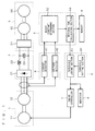
- FIG. 1 is a diagram schematically illustrating the configuration of a refrigerating apparatus to which an engine life predicting apparatus according to a first preferred embodiment of the present invention is applied.
- This refrigerating apparatus includes an engine generator 1, a converter 2, a compressor driving block 3, a detecting block 4, an operating block, 5, a judging block 6, an engine controller 7, an indicator 8, and a nonvolatile memory 9.
- This refrigerating apparatus is provided in, e.g. a trailer, and includes a mechanism for cooling the inside of the trailer's container (heat exchangers, fans, etc.), but they are not graphically shown because they are not related to the essence of the present invention.
- the engine generator 1 includes an engine 11 and a generator 12.
- the generator 12 is driven with the engine 11 as a power source, to generate three-phase alternating current and supply to the converter 2, for example.
- the generator 12 may generate single-phase alternating current, and it can be a generator of any kind, such as a permanent magnet field type generator, induction generator, wound-field generator, reluctance generator, etc.
- the converter 2 includes a diode bridge 21, a reactance 22, and a smoothing capacitor 23.
- the diode bridge 21 converts the alternating-current voltage from the engine generator 1 into direct-current voltage.
- the reactance 22 reduces ripple of the direct-current voltage from the diode bridge 21.
- the smoothing capacitor 23 smoothes the direct-current voltage from the diode bridge 21.
- the compressor driving block 3 includes an inverter 31, a motor 32, and a compressor 33.
- the inverter 31 is controlled by an inverter controller not shown, and converts the direct current from the converter 2 into arbitrary alternating current, and supplies it to the motor 32.
- the motor 32 rotates by receiving the alternating current from the inverter 31, to drive the compressor 33.
- the compressor 33 compresses refrigerant and causes it to circulate in a refrigerant circuit not shown.
- the detecting block 4 is connected to the input side of the converter 2, and includes a current detector 41 and a voltage detector 42.
- the current detector 41 detects the current value outputted from the engine generator 1.
- the voltage detector 42 detects the voltage value outputted from the engine generator 1.
- the operating block 5 includes a weight constant determining section 52 and an integral time calculating section 53.
- the weight constant determining section 52 determines a weight constant on the basis of the current value detected by the current detector 41 and the voltage value detected by the voltage detector 42.
- FIG. 2 shows an example of a weighting table used to determine the weight constant.
- the horizontal axis shows the voltage value and the vertical axis shows the current value, and the voltage value and the current value are respectively divided into a plurality of ranges.
- Weight constants are set in the individual regions specified by the combinations of the voltage value ranges and current value ranges.
- the weight constants kij are obtained by actually measuring the life Lij of the engine 11 under conditions defined by all combinations of the voltage value ranges V0 to V3 and the current value ranges A0 to A4, for example. Specifically, for example, the weight constants kij are set such that kij ⁇ Lij takes a constant value (e.g. a mean value of Lij) for all combinations. However, it is not always necessary to actually measure the life for all combinations, but the life may be measured only under major conditions to determine the weight constants under those conditions, and the other weight constants may be obtained by approximation.
- a constant value e.g. a mean value of Lij
- the weight constants kij differ depending on characteristics of the engine 11, but they generally becomes larger toward the upper right corner in the weighting table where the load on the engine 11 is heavier.
- the weight constant determining section 52 determines the weight constant kij specified by the combination of the current value detected by the current detector 41 and the voltage value detected by the voltage detector 42.
- the integral time calculating section 53 weights the operating time of the engine 11 and integrates the weighted operating time to calculate an integral time. Specifically, when the engine 11 operates for an operating time tij under a condition where the weight constant is kij (the voltage value is in the range Vi and the current value is in the range Aj), for example, the integral time calculating section 53 calculates the integral time T according to Expression below. Where symbol ⁇ indicates the sum total about the subscripts i, j.
- the integral time calculating section 53 records the calculated integral time T into the nonvolatile memory 9.
- the judging block 6 includes a threshold judging section 61 and a threshold setting section 62.
- the threshold judging section 61 compares the integral time T calculated by the integral time calculating section 53 and a previously set reference time, and predicts the life of the engine 11.
- the threshold setting section 62 sets the reference time. Specifically, the reference time is set in addition when the weight constants are previously set by actual measurement. For example, the reference time is set at 100 hours before kij ⁇ Lij (e.g. a mean value of Lij).
- the threshold judging section 61 judges that the integral time T exceeds the previously set reference time, it gives a notification of that fact to the engine controller 7 and the indicator 8.
- the engine controller 7 restricts at least one of the maximum number of rotations and the maximum output of the engine 11. This operation can delay the time at which the engine 11 stops because of the life. Also, since the output of the engine 11 is restricted, the output of the compressor 33 is restricted as a result, which also can delay the time at which the compressor 33 stops because of the life.
- the indicator 8 externally indicates, e.g. with sound or display, that the integral time has exceeded the reference time. This operation enables the user to recognize that the life of the engine 11 is near, and to be urged to take measures, such as maintenance.
- the life of the engine 11 is predicted by detecting the current and voltage outputted from the engine generator 1. It is possible to provide a life predicting apparatus with high reliability because the detecting block 4 can be made of electric circuitry. It is also possible to provide a life predicting apparatus at low costs because no detectors are needed for detecting the number of rotations, torque, etc. of the engine 11.
- a plurality of reference times may be set.
- the threshold judging section 61 compares reference times T1, T2, T3 (T1 ⁇ T2 ⁇ T3) set by the threshold setting section 62 and the integral time T calculated by the integral time calculating section 53. Then, when the integral time T exceeds the reference time T1, it gives a notification of that fact to the engine controller 7 and the indicator 8.
- the engine controller 7 restricts the maximum number of rotations of the engine 11 to N1, and/or restricts the maximum output to P1. Also, receiving the same notification, the indicator 8 makes an external indication with sound or display for caution, for example.
- the threshold judging section 61 gives a notification of that fact to the engine controller 7 and the indicator 8.
- the engine controller 7 restricts the maximum number of rotations of the engine 11 to N2 ( ⁇ N1), and/or restricts the maximum output to P2 ( ⁇ P1), Receiving the same notification, the indicator makes an external indication with sound or display for warning, for example.
- the threshold judging section 61 gives a notification of that fact to the engine controller 7 and the indicator 8.
- the engine controller 7 stops the engine 11. Also, receiving the same notification, the indicator makes an external indication with sound or display to indicate that the engine 11 has been stopped because its life approaches.
- the indicator 8 When the indicator 8 is provided in the cab of a trailer, for example, it is possible to directly make the user recognize the caution, warning, stoppage, etc.
- the nonvolatile memory 9 may be detachably attached to the refrigerating apparatus.
- the nonvolatile memory 9 used before the replacement can be detached and attached to the new life predicting apparatus, so that the life of the engine 11 can be predicted without losing the existing integral time.
- FIG. 3 is a diagram schematically illustrating the configuration of a refrigerating apparatus to which an engine life predicting apparatus of a second preferred embodiment of the present invention is applied.
- the detecting block 4 further includes a frequency detector 43
- the operating block 5 further includes a power calculating section 51.
- the frequency detector 43 detects the frequency of the alternating-current voltage outputted from the engine generator 1.
- the power calculating section 51 calculates the power by using the current value detected by the current detector 41 and the voltage value detected by the voltage detector 42.
- the weight constant determining section 52 calculates the number of rotations of the engine 11 on the basis of the frequency detected by the frequency detector 43, and determines the weight constant on the basis of the power calculated by the power calculating section 51 and the number of rotations.
- FIG. 4 shows an example of a weighting table used to determine the weight constant.
- the horizontal axis shows the number of rotations
- the vertical axis shows the power
- the number of rotations and power are each divided into a plurality of ranges. Then, weight constants are set in the individual regions specified by the combinations of the ranges of the number of rotations and the ranges of power.
- the weight constants mij are obtained by measuring the life Lij under the conditions of all combinations of the ranges R0 to R3 of the number of rotations and the ranges P0 to P4 of power, for example.
- the weight constants mij are set such that mij ⁇ Lij takes a constant value (e.g. a mean value of Lij) for all combinations, for example. It is not always necessary to measure the life for all combinations, but the life may be measured only under major conditions to determine the weight constants under those conditions, and the other weight constants may be obtained by approximation.
- a constant value e.g. a mean value of Lij
- the weight constant determining section 52 determines the weight constant mij that is specified by the combination of the number of rotations calculated on the basis of the frequency detected by the frequency detector 43 and the power calculated by the power calculating section 51.
- the integral time calculating section 53 weights the operating time of the engine 11, and integrates the weighted operating time to calculate the integral time. Specifically, when the engine 11 operates for an operating time tij under a condition where the weight constant is mij (the number of rotations is in the range Ri and the power is in the range Pj), for example, the integral time calculating section 53 obtains the integral time T according to Expression below. Where symbol ⁇ indicates the sum total about the subscripts i, j.
- the life of the engine 11 can be predicated on the basis of the alternating-current power and frequency outputted from the engine generator 1.
- the accuracy of life predication can be enhanced because the life predication takes into account the number of rotations of the engine.
- FIG. 5 is a diagram schematically illustrating the configuration of a refrigerating apparatus to which an engine life predicting apparatus of a third preferred embodiment of the present invention is applied. As compared with that of the second preferred embodiment, a detecting block 4 detects the direct current outputted from the converter 2.
- a current detector 41 detects the current value outputted from the converter 2 on the low potential side.
- a voltage detector 42 detects the voltage across the high potential and low potential outputted from the converter 2.
- a frequency detector 43 detects the frequency of the alternating-current voltage from the engine generator 1 by detecting the frequency of ripple of the direct-current voltage outputted from the converter 2.
- the frequency of ripple of the direct-current voltage from the converter 2 usually has the relation of six times the frequency of the alternating-current voltage from the engine generator 1.
- a power calculating section 51 calculates the power by using the current value detected by the current detector 41 and the voltage value detected by the voltage detector 42.
- a weight constant determining section 52 determines the weight constant on the basis of the power calculated by the power calculating section 51 and the number of rotations of the engine 11 calculated from the frequency detected by the frequency detector 43.
- the weight constants are set by a method similar to that of the second preferred embodiment, but it is needless to say that the weight constants are set on the basis of the power and frequency outputted from the converter 2.
- the detecting block 4 detects the direct current outputted from the converter 2, and the life of the engine 11 can be predicted on the basis of the detected current value, voltage value, and frequency. Also, the accuracy of the detection by the detecting block 4 is enhanced because the voltage can be detected on the basis of the low potential side of the voltage outputted from the converter 2.
- the current detector 41 and voltage detector 42 are already provided to control the inverter 31, so that they can be diverted to reduce manufacturing costs.
- Detecting the frequency is easy when the detecting block 4 detects the alternating current between the engine generator 1 and the converter 2 as described in the second preferred embodiment.
- the third preferred embodiment has been described by using the detecting block 4 and the operating block 5 of the second preferred embodiment, but the detecting block 4 and the operating block 5 of the first preferred embodiment may be used.
- the method of setting weight constants uses the table shown in FIG. 2 .
- FIG. 6 is a diagram schematically illustrating the configuration of a refrigerating apparatus to which an engine life predicting apparatus of a fourth preferred embodiment is applied.
- the converter 2 is formed of a rectifier including the diode bridge 21.
- the converter 2 includes switch elements 24 to 29 and a smoothing capacitor 23.
- the converter 2 is controlled by a converter controller 20.
- the inverter 31 is controlled by an inverter controller 34.
- the switches 24 to 29 are each formed of a parallel connection of a transistor and a free-wheeling diode.
- a set of series-connected switch elements 24 and 25, a set of switch elements 26 and 27, and a set of switch elements 28 and 29, are each connected in parallel.
- the switch elements 24 to 29 are each appropriately controlled by the converter controller 20, and convert the alternating current outputted from the engine generator 1 into direct current.
- an engine controller 7 controls the number of rotations of the engine 11 according to the load on the engine generator 1.
- the output voltage of the converter 2 and the output voltage or output frequency of the inverter 31 are detected, and the number of rotations of the engine 11 is controlled according to the output voltages.
- Such an engine controller 7 enables proper operation according to the load on the engine 11.
- the converter controller 20 controls the converter 2 according to the variation of the number of rotations of the engine 11 so that desired output voltage is outputted from the converter 2.
- the detecting block 4 detects the current value and voltage value outputted from the engine generator 1, and the operating block 5 weights the operating time of the engine 11 by using a weight constant determined on the basis of the current value and voltage value, and integrates the weighted operating time to calculate the integral time.
- the judging block 6 compares the integral time calculated by the operating block 5 and a reference time to predict the life of the engine 11. For example, when the engine controller 7 controls the number of rotations of the engine 11 according to the output voltage of the converter 2, the judging block 6 gives a notification to the converter controller 20 when it judges that the integral time exceeds the reference time.
- the converter controller 20 restricts the maximum output voltage from the converter 2.
- the engine controller 7 thus controls the number of rotations of the engine 11 according to the output voltage from the converter 2, and so the maximum number of rotations of the engine 11 is restricted as a result, and the time at which the engine 11 stops because of the life can be delayed. Also, restricting the maximum output voltage of the converter 2 restricts the output voltage from the inverter 31, and therefore the life of the compressor 33 can be prolonged.
- the judging block 6 may give a notification directly to the engine controller 7 when it judges that the integral time exceeds the reference time. Then, receiving the notification, the engine controller 7 restricts at least one of the maximum output and the maximum number of rotations of the engine 11.
- the judging block 6 gives a notification to the inverter controller 34 when it judges that the integral time exceeds the reference time. Receiving the notification, the inverter controller 34 restricts at least one of the maximum output power and maximum output frequency of the inverter 31. This can prolong the life of the compressor 33.
- the engine controller 7 thus controls the number of rotations of the engine 11 according to the output voltage or output frequency of the inverter 31, and so the maximum number of rotations of the engine 11 is restricted as a result, and thus the time at which the engine 11 stops because of the life can be delayed.
- the inverter 31 is controlled by an inverter controller 34 thought not graphically shown. Accordingly, when the engine controller 7 controls the number of rotations of the engine 11 according to the output voltage or output frequency of the inverter 31, at least one of the maximum output power and maximum output frequency of the inverter 31 may be restricted also in the first to third preferred embodiments.
- the part including the converter 2 and the inverter 31 may be formed of a matrix converter 35.
- the matrix converter 35 is controlled by a matrix converter controller 36, and the alternating current from the engine generator 1 can be converted directly into arbitrary alternating current and supplied to the motor 32.
- the detecting block 4 detects the alternating current on the input side of the matrix converter 35, and the operating block 5 and the judging block 6 operate to predict the life of the engine 11.
- the matrix converter controller 36 restricts at least one of the maximum output power and maximum frequency power outputted from the matrix converter 35. This can prolong the life of the engine 11.
- the judging block 6 may give a notification directly to the engine controller 7 when it judges that the integral time exceeds the reference time. Then, receiving the notification, the engine controller 7 restricts at least one of the maximum output and the maximum number of rotations of the engine 11.
- a plurality of reference times may be provided and the maximum output may be restricted according to each of the reference times.
- the fourth preferred embodiment has been described by using the detecting block 4 and the operating block 5 of the first preferred embodiment, but the detecting block 4 and the operating block 5 of the second or third preferred embodiment may be used.
- FIG. 8 illustrates a refrigerating apparatus to which an engine life predicting apparatus of a fifth preferred embodiment of the present invention is applied. While the first to fourth preferred embodiments predict the life of the engine 11, the fifth preferred embodiment is capable of predicting the life of the compressor.
- a detecting block 4 detects the alternating current outputted from the inverter 31.
- a current detector 41 detects the current value outputted from the inverter 31, and a voltage detector 42 detects the voltage value outputted from the inverter 31.
- an operating block 5 weights the operating time of the compressor 33 and integrates the weighted operating time to calculate an integral time.
- the weight constants are set by a method similar to that of the first preferred embodiment, but the weight constants are of course set by actually measuring the life of the compressor 33 under conditions of the combinations of the current value and voltage value outputted from the inverter 31.
- a judging block 6 compares the integral time and a reference time, and gives a notification to the engine controller 7, indicator 8, converter controller 20, and inverter controller 34 when the integral time exceeds the reference time. It is not always necessary for the judging block 6 to give a notification to all of them, but it may give a notification to at least one of them.
- the indicator 8 externally indicates, with sound or display, that the integral time of the compressor has exceeded the reference time. This enables the user to recognize that the life of the compressor 33 is near.
- the engine controller 7 restricts at least one of the maximum output and maximum number of rotations of the engine 11, or stops the engine 11.
- the converter controller 20 restricts the maximum output voltage of the converter 2.
- the inverter controller 34 restricts at least one of the maximum output power and maximum frequency of the inverter 31. This delays the time at which the compressor 33 stops because of the life, and it is possible, by stopping the engine 11, to prevent failures of the compressor expires by the life.
- the fifth preferred embodiment has been described by using the detecting block 4 and the operating block 5 of the first preferred embodiment, but the detecting block 4 and the operating block 5 of the second preferred embodiment may be used. Also, the part including the converter 2 and the inverter 31 may be formed of a matrix converter.
- the fifth preferred embodiment may be applied to any of the first to fourth preferred embodiments. That is, the lives of the engine 11 and the compressor 33 may be predicted by detecting the output from the engine generator 1 or the converter 2, also detecting the output from the inverter 31, determining a weight constant for the engine 11 and a weight constant for the compressor 33 with different weighting tables, comparing the integral time of the engine 11 and a reference time for the engine 11, and comparing the integral time of the compressor 33 and a reference time for the compressor 33.
- any of the first to fifth preferred embodiments can be applied in combination. Also, aspects in which the engine life predicting apparatus of the present invention is applied to a refrigerating apparatus have been described, but they are illustrative and not restrictive; the engine life predicting apparatus of the present invention can be applied to any apparatuses that are supplied with power by an engine generator.
Landscapes
- Physics & Mathematics (AREA)
- Engineering & Computer Science (AREA)
- General Physics & Mathematics (AREA)
- Mechanical Engineering (AREA)
- Thermal Sciences (AREA)
- General Engineering & Computer Science (AREA)
- Testing Of Devices, Machine Parts, Or Other Structures Thereof (AREA)
- Control Of Vehicle Engines Or Engines For Specific Uses (AREA)
- Testing Of Engines (AREA)
- Tests Of Circuit Breakers, Generators, And Electric Motors (AREA)
- Combined Controls Of Internal Combustion Engines (AREA)
Abstract
Description
- The present invention relates to an engine life predicting apparatus and a refrigerating apparatus, and particularly to life prediction using a generator with an engine as a power source.
-
Patent Documents 1 to 4 disclose techniques for life prediction of an engine using the number of rotations, output torque, power consumption, etc. of the engine. For example, inPatent Document 1, a sensor for detecting the number of rotations of an engine and a sensor for detecting the rack position detect the number of rotations of the engine and the rack position (a substitutional value of engine torque), a weight is determined on the basis of the detected number of rotations and rack position, the operating time of the engine is weighted by using the weight, and the life of the engine is calculated. -
- Patent Document 1: Japanese Patent Application Laid-Open No.
11-211622 1999 - Patent Document 2: Japanese Patent Application Laid-Open No.
06-010748 1994 - Patent Document 3: Japanese Patent Application Laid-Open No.
2001-011900 - Patent Document 4: Japanese Patent Application Laid-Open No.
2005-171940 - However, the techniques described in
Patent Documents 1 to 4 need sensors, like a detector for detecting the number of rotations of the engine and a detector for detecting torque, leading to lower reliability and increased manufacturing costs. - Accordingly, an object of the present invention is to provide an engine life predicting apparatus at low costs and with high reliability.
- According to a first aspect of the engine life predicting apparatus of the present invention, an engine life predicting apparatus comprises: a detecting block (4) including a current detector (41) that detects a current value outputted from a generator (12) with an engine (11) as a power source, and a voltage detector (42) that detects a voltage value outputted from said generator; an operating block (5) that weights an operating time of said engine by using a weight constant determined on the basis of said current value and said voltage value, and that integrates weighted said operating time to calculate an integral time; and a judging block (6) that judges a life of said engine by comparing said integral time and a previously set reference value.
- According to a second aspect of the engine life predicting apparatus of the present invention, in the engine life predicting apparatus of the first aspect, said detecting block further includes a frequency detector (43) that detects a frequency of alternating current outputted from said generator, and said operating block calculates a power value from said current value and said voltage value, and determines said weight constant on the basis of said power value and said frequency.
- According to a third aspect of the engine life predicting apparatus of the present invention, the engine life predicting apparatus of the first or second aspect further comprises a converter (2) that converts alternating current outputted from said generator into direct current, and said detecting block is connected to at least an input side of said converter.
- According to a fourth aspect of the engine life predicting apparatus of the present invention, the engine life predicting apparatus of the first or second aspect further comprises a converter (2) that converts alternating current outputted from said generator into direct current, and said detecting block is connected to at least an output side of said converter.
- According to a fifth aspect of the engine life predicting apparatus of the present invention, the engine life predicting apparatus of any of the first to fourth aspects further comprises a power conversion device (2, 31, 35) that converts alternating-current power outputted from said generator; and a power conversion device controller (20, 34, 36) that restricts at least one of a maximum output power and a maximum output frequency of said power conversion device when said judging block judges that said integral time exceeds said reference value.
- According to a sixth aspect of the engine life predicting apparatus of the present invention, in the engine life predicting apparatus of the fifth aspect, said reference value includes a plurality of previously set reference values, and said power conversion device controller restricts at least one of said maximum output power and said maximum output frequency according to each of said reference values.
- According to a seventh aspect of the engine life predicting apparatus of the present invention, the engine life predicting apparatus of the fifth or sixth aspect further comprises a load (32, 33) that is supplied with power from said power conversion device, wherein said detecting block is connected to an output side of said power conversion device, said operating block weights an operating time of said load by using said weight constant and integrates the weighted operating time of said load to calculate an integral time, and said integral time and a previously set reference value are compared to judge a life of said load.
- According to an eighth aspect of the engine life predicting apparatus of the present invention, the engine life predicting apparatus of any of the first to seventh aspects further comprises an indicator (8) that makes an external indication when said judging block judges that said integral time exceeds said reference value.
- According to a ninth aspect of the engine life predicting apparatus of the present invention, in the engine life predicting apparatus of the eighth aspect, said reference value includes a plurality of previously set reference values, and said indicator makes an indication according to each of said reference values.
- According to a tenth aspect of the engine life predicting apparatus of the present invention, the engine life predicting apparatus of any of the first to ninth aspects further comprises an engine controller (7) that restricts at least one of a maximum output and a maximum number of rotations of said engine when said judging block judges that said integral time exceeds said reference value.
- According to an eleventh aspect of the engine life predicting apparatus of the present invention, in the engine life predicting apparatus of the tenth aspect, said engine controller stops said engine when said judging block judges that said integral time exceeds said reference value.
- According to a twelfth aspect of the engine life predicting apparatus of the present invention, in the engine life predicting apparatus of the tenth aspect, said reference value includes a plurality of previously set reference values, and said engine controller restricts at least one of the maximum output and the maximum number of rotations according to each of said reference values.
- According to a thirteenth aspect of the engine life predicting apparatus of the present invention, the engine life predicting apparatus of the third or fourth aspect further comprises a converter controller (20) that restricts a maximum output voltage of said converter when said judging block judges that said integral time exceeds said reference value.
- According to a fourteenth aspect of the engine life predicting apparatus of the present invention, in the engine life predicting apparatus of the thirteenth aspect, said reference value includes a plurality of previously set reference values, and said converter controller restricts the maximum output voltage according to each of said reference values.
- According to a fifteenth aspect of the engine life predicting apparatus of the present invention, in the engine life predicting apparatus of any of the first to fourteenth aspects, said generator drives a motor (32).
- According to a sixteenth aspect of the engine life predicting apparatus of the present invention, the engine life predicting apparatus of any of the first to fifteenth aspects further comprises a nonvolatile recording medium (9) that is replaceable and that records said integral time.
- According to a first aspect of the refrigerating apparatus of the present invention, a refrigerating apparatus comprises the engine life predicting apparatus according to any of the first to sixteenth aspects.
- According to the first aspect of the engine life predicting apparatus of the present invention, the detecting block can be made of electric circuitry, and so an engine life predicting apparatus can be provided at low costs and with high reliability.
- According to the second aspect of the engine life predicting apparatus of the present invention, the frequency of the alternating current outputted from the generator is in a unique relation with the number of rotations of the engine, and the life prediction can be made taking the number of rotations into account, so that the accuracy of the life prediction is enhanced.
- According to the third aspect of the engine life predicting apparatus of the present invention, the detecting block makes detection on the input side of the converter, and so the frequency of the alternating current can be detected easily.
- According to the fourth aspect of the engine life predicting apparatus of the present invention, it is possible to enhance the detecting accuracy because the detecting block can measure the voltage on the basis of the low output potential of the converter.
- According to the fifth, tenth, and thirteenth aspects of the engine life predicting apparatus of the present invention, it is possible to delay the time at which the engine stops because of life.
- According to the sixth, twelfth, and fourteenth aspects of the engine life predicting apparatus of the present invention, it is possible to more minutely delay the time at which the engine stops because of the life.
- According to the seventh aspect of the engine life predicting apparatus of the present invention, it is possible to further predict the life of the load.
- According to the eighth aspect of the engine life predicting apparatus of the present invention, the user can easily confirm the life of the engine.
- According to the ninth aspect of the engine life predicting apparatus of the present invention, the user can minutely know the life of the engine to take quick measures.
- According to the eleventh aspect of the engine life predicting apparatus of the present invention, the engine is stopped before its life, and thus to prevent failures of the engine by the life.
- According to the fifteenth aspect of the engine life predicting apparatus of the present invention, the detecting block can be made of electric circuitry, and there is no need for a sensor for measuring motor torque.
- According to the sixteenth aspect of the engine life predicting apparatus of the present invention, when the detecting block, integral time calculating block, judging block, and recording medium are provided on the same substrate, for example, even when the substrate is replaced due to a failure, the recording medium can be attached to the new substrate so that the integral time is not lost.
- According to the first aspect of the refrigerating apparatus of the present invention, the detecting block can be made of electric circuitry, and so a refrigerating apparatus that predicts the life of the engine can be provided at low costs and with high reliability.
- These and other objects, features, aspects and advantages of the present invention will become more apparent from the following detailed description of the present invention when taken in conjunction with the accompanying drawings.
-
- [
FIG. 1 ] A schematic diagram illustrating the configuration of a refrigerating apparatus to which an engine life predicting apparatus of a first preferred embodiment is applied. - [
FIG. 2 ] A diagram illustrating a weighting table. - [
FIG. 3 ] A schematic diagram illustrating the configuration of a refrigerating apparatus to which an engine life predicting apparatus of a second preferred embodiment is applied. - [
FIG. 4 ] A diagram illustrating a weighting table. - [
FIG. 5 ] A schematic diagram illustrating the configuration of a refrigerating apparatus to which an engine life predicting apparatus of a third preferred embodiment is applied. - [
FIG. 6 ] A schematic diagram illustrating the configuration of a refrigerating apparatus to which an engine life predicting apparatus of a fourth preferred embodiment is applied. - [
FIG. 7 ] A schematic diagram illustrating the configuration of a refrigerating apparatus to which an engine life predicting apparatus of the fourth preferred embodiment is applied. - [
FIG. 8 ] A schematic diagram illustrating the configuration of a refrigerating apparatus to which an engine life predicting apparatus of a fifth preferred embodiment is applied. - The engine life predicting apparatus according to the present invention will now be described referring to the drawings. Like reference characters denote like or corresponding parts, and the same contents will not be described repeatedly.
-
FIG. 1 is a diagram schematically illustrating the configuration of a refrigerating apparatus to which an engine life predicting apparatus according to a first preferred embodiment of the present invention is applied. - This refrigerating apparatus includes an
engine generator 1, aconverter 2, acompressor driving block 3, a detectingblock 4, an operating block, 5, ajudging block 6, anengine controller 7, anindicator 8, and anonvolatile memory 9. This refrigerating apparatus is provided in, e.g. a trailer, and includes a mechanism for cooling the inside of the trailer's container (heat exchangers, fans, etc.), but they are not graphically shown because they are not related to the essence of the present invention. - The
engine generator 1 includes anengine 11 and agenerator 12. Thegenerator 12 is driven with theengine 11 as a power source, to generate three-phase alternating current and supply to theconverter 2, for example. Alternatively, thegenerator 12 may generate single-phase alternating current, and it can be a generator of any kind, such as a permanent magnet field type generator, induction generator, wound-field generator, reluctance generator, etc. - The
converter 2 includes adiode bridge 21, areactance 22, and asmoothing capacitor 23. Thediode bridge 21 converts the alternating-current voltage from theengine generator 1 into direct-current voltage. Thereactance 22 reduces ripple of the direct-current voltage from thediode bridge 21. The smoothingcapacitor 23 smoothes the direct-current voltage from thediode bridge 21. - The
compressor driving block 3 includes aninverter 31, amotor 32, and acompressor 33. Theinverter 31 is controlled by an inverter controller not shown, and converts the direct current from theconverter 2 into arbitrary alternating current, and supplies it to themotor 32. Themotor 32 rotates by receiving the alternating current from theinverter 31, to drive thecompressor 33. Thecompressor 33 compresses refrigerant and causes it to circulate in a refrigerant circuit not shown. - The detecting
block 4 is connected to the input side of theconverter 2, and includes acurrent detector 41 and avoltage detector 42. Thecurrent detector 41 detects the current value outputted from theengine generator 1. Thevoltage detector 42 detects the voltage value outputted from theengine generator 1. - The
operating block 5 includes a weightconstant determining section 52 and an integraltime calculating section 53. - The weight
constant determining section 52 determines a weight constant on the basis of the current value detected by thecurrent detector 41 and the voltage value detected by thevoltage detector 42. Specifically,FIG. 2 shows an example of a weighting table used to determine the weight constant. In the weighting table, the horizontal axis shows the voltage value and the vertical axis shows the current value, and the voltage value and the current value are respectively divided into a plurality of ranges. Weight constants are set in the individual regions specified by the combinations of the voltage value ranges and current value ranges. - Specifically, in the weighting table shown in
FIG. 2 , the voltage value is divided into four ranges Vi (i=0 to 3), and the current value is divided into four ranges Aj (j=0 to 3), and weight constants kij are previously set in the regions specified by the combinations of the voltage value ranges Vi and current value ranges Aj. - The weight constants kij are obtained by actually measuring the life Lij of the
engine 11 under conditions defined by all combinations of the voltage value ranges V0 to V3 and the current value ranges A0 to A4, for example. Specifically, for example, the weight constants kij are set such that kij·Lij takes a constant value (e.g. a mean value of Lij) for all combinations. However, it is not always necessary to actually measure the life for all combinations, but the life may be measured only under major conditions to determine the weight constants under those conditions, and the other weight constants may be obtained by approximation. - The weight constants kij differ depending on characteristics of the
engine 11, but they generally becomes larger toward the upper right corner in the weighting table where the load on theengine 11 is heavier. - By using the weighting table, the weight
constant determining section 52 determines the weight constant kij specified by the combination of the current value detected by thecurrent detector 41 and the voltage value detected by thevoltage detector 42. - On the basis of the weight constant kij determined by the weight
constant determining section 52, the integraltime calculating section 53 weights the operating time of theengine 11 and integrates the weighted operating time to calculate an integral time. Specifically, when theengine 11 operates for an operating time tij under a condition where the weight constant is kij (the voltage value is in the range Vi and the current value is in the range Aj), for example, the integraltime calculating section 53 calculates the integral time T according to Expression below. Where symbol Σ indicates the sum total about the subscripts i, j. -

- Also, the integral
time calculating section 53 records the calculated integral time T into thenonvolatile memory 9. - The judging
block 6 includes athreshold judging section 61 and athreshold setting section 62. Thethreshold judging section 61 compares the integral time T calculated by the integraltime calculating section 53 and a previously set reference time, and predicts the life of theengine 11. - The
threshold setting section 62 sets the reference time. Specifically, the reference time is set in addition when the weight constants are previously set by actual measurement. For example, the reference time is set at 100 hours before kij·Lij (e.g. a mean value of Lij). - Then, when the
threshold judging section 61 judges that the integral time T exceeds the previously set reference time, it gives a notification of that fact to theengine controller 7 and theindicator 8. - Receiving the notification, the
engine controller 7 restricts at least one of the maximum number of rotations and the maximum output of theengine 11. This operation can delay the time at which theengine 11 stops because of the life. Also, since the output of theengine 11 is restricted, the output of thecompressor 33 is restricted as a result, which also can delay the time at which thecompressor 33 stops because of the life. - Also, receiving the notification, the
indicator 8 externally indicates, e.g. with sound or display, that the integral time has exceeded the reference time. This operation enables the user to recognize that the life of theengine 11 is near, and to be urged to take measures, such as maintenance. - In this way, the life of the
engine 11 is predicted by detecting the current and voltage outputted from theengine generator 1. It is possible to provide a life predicting apparatus with high reliability because the detectingblock 4 can be made of electric circuitry. It is also possible to provide a life predicting apparatus at low costs because no detectors are needed for detecting the number of rotations, torque, etc. of theengine 11. - According to the present invention, a plurality of reference times may be set. For example, the
threshold judging section 61 compares reference times T1, T2, T3 (T1<T2<T3) set by thethreshold setting section 62 and the integral time T calculated by the integraltime calculating section 53. Then, when the integral time T exceeds the reference time T1, it gives a notification of that fact to theengine controller 7 and theindicator 8. - Receiving the notification of the fact that the integral time T has exceeded the reference time T1, the
engine controller 7 restricts the maximum number of rotations of theengine 11 to N1, and/or restricts the maximum output to P1. Also, receiving the same notification, theindicator 8 makes an external indication with sound or display for caution, for example. - When the integral time T exceeds the reference time T2, the
threshold judging section 61 gives a notification of that fact to theengine controller 7 and theindicator 8. Receiving the notification of the fact that the integral time T has exceeded the reference time T2, theengine controller 7 restricts the maximum number of rotations of theengine 11 to N2 (<N1), and/or restricts the maximum output to P2 (<P1), Receiving the same notification, the indicator makes an external indication with sound or display for warning, for example. - When the integral time T exceeds the reference time T3, the
threshold judging section 61 gives a notification of that fact to theengine controller 7 and theindicator 8. Receiving the notification that the integral time T has exceeded the reference time T2, theengine controller 7 stops theengine 11. Also, receiving the same notification, the indicator makes an external indication with sound or display to indicate that theengine 11 has been stopped because its life approaches. - This makes it possible to minutely prolong the life of the
engine 11, and to allow the user to minutely know the life of theengine 11 to take quick measures. This also makes it possible to prevent failures of theengine 11 because theengine 11 is stopped before the life of theengine 11. Furthermore, also in this case, the life of thecompressor 33 can be minutely prolonged as a result, and failures of thecompressor 33 by the life can be prevented. - When the
indicator 8 is provided in the cab of a trailer, for example, it is possible to directly make the user recognize the caution, warning, stoppage, etc. - Also, according to the present invention, the
nonvolatile memory 9 may be detachably attached to the refrigerating apparatus. For example, when the life predicting apparatus is replaced, thenonvolatile memory 9 used before the replacement can be detached and attached to the new life predicting apparatus, so that the life of theengine 11 can be predicted without losing the existing integral time. -
FIG. 3 is a diagram schematically illustrating the configuration of a refrigerating apparatus to which an engine life predicting apparatus of a second preferred embodiment of the present invention is applied. As compared with that of the first preferred embodiment, the detectingblock 4 further includes afrequency detector 43, and theoperating block 5 further includes apower calculating section 51. - The
frequency detector 43 detects the frequency of the alternating-current voltage outputted from theengine generator 1. - The
power calculating section 51 calculates the power by using the current value detected by thecurrent detector 41 and the voltage value detected by thevoltage detector 42. - The weight
constant determining section 52 calculates the number of rotations of theengine 11 on the basis of the frequency detected by thefrequency detector 43, and determines the weight constant on the basis of the power calculated by thepower calculating section 51 and the number of rotations. Specifically,FIG. 4 shows an example of a weighting table used to determine the weight constant. In the weighting table, the horizontal axis shows the number of rotations, and the vertical axis shows the power, and the number of rotations and power are each divided into a plurality of ranges. Then, weight constants are set in the individual regions specified by the combinations of the ranges of the number of rotations and the ranges of power. - Specifically, in the weighting table illustrated in
FIG. 4 , the number of rotations is divided into four regions Ri (i=0 to 3), and the power is divided into four regions Pj (j=0 to 3), and weight constants mij are previously set in the regions specified by the combinations of the ranges Ri of the number of rotations and the ranges Pj of power. The weight constants mij are obtained by measuring the life Lij under the conditions of all combinations of the ranges R0 to R3 of the number of rotations and the ranges P0 to P4 of power, for example. - Specifically, the weight constants mij are set such that mij·Lij takes a constant value (e.g. a mean value of Lij) for all combinations, for example. It is not always necessary to measure the life for all combinations, but the life may be measured only under major conditions to determine the weight constants under those conditions, and the other weight constants may be obtained by approximation.
- Then, by using the weighting table, the weight
constant determining section 52 determines the weight constant mij that is specified by the combination of the number of rotations calculated on the basis of the frequency detected by thefrequency detector 43 and the power calculated by thepower calculating section 51. - On the basis of the weight constant mij determined by the weight
constant determining section 52, the integraltime calculating section 53 weights the operating time of theengine 11, and integrates the weighted operating time to calculate the integral time. Specifically, when theengine 11 operates for an operating time tij under a condition where the weight constant is mij (the number of rotations is in the range Ri and the power is in the range Pj), for example, the integraltime calculating section 53 obtains the integral time T according to Expression below. Where symbol Σ indicates the sum total about the subscripts i, j. -

- Thus, the life of the
engine 11 can be predicated on the basis of the alternating-current power and frequency outputted from theengine generator 1. The accuracy of life predication can be enhanced because the life predication takes into account the number of rotations of the engine. -
FIG. 5 is a diagram schematically illustrating the configuration of a refrigerating apparatus to which an engine life predicting apparatus of a third preferred embodiment of the present invention is applied. As compared with that of the second preferred embodiment, a detectingblock 4 detects the direct current outputted from theconverter 2. - A
current detector 41 detects the current value outputted from theconverter 2 on the low potential side. Avoltage detector 42 detects the voltage across the high potential and low potential outputted from theconverter 2. - A
frequency detector 43 detects the frequency of the alternating-current voltage from theengine generator 1 by detecting the frequency of ripple of the direct-current voltage outputted from theconverter 2. When thegenerator 12 is a three-phase electric rotating machine, the frequency of ripple of the direct-current voltage from theconverter 2 usually has the relation of six times the frequency of the alternating-current voltage from theengine generator 1. - Then, as in the second preferred embodiment, a
power calculating section 51 calculates the power by using the current value detected by thecurrent detector 41 and the voltage value detected by thevoltage detector 42. A weightconstant determining section 52 determines the weight constant on the basis of the power calculated by thepower calculating section 51 and the number of rotations of theengine 11 calculated from the frequency detected by thefrequency detector 43. The weight constants are set by a method similar to that of the second preferred embodiment, but it is needless to say that the weight constants are set on the basis of the power and frequency outputted from theconverter 2. - In this way, the detecting
block 4 detects the direct current outputted from theconverter 2, and the life of theengine 11 can be predicted on the basis of the detected current value, voltage value, and frequency. Also, the accuracy of the detection by the detectingblock 4 is enhanced because the voltage can be detected on the basis of the low potential side of the voltage outputted from theconverter 2. - Also, usually, the
current detector 41 andvoltage detector 42 are already provided to control theinverter 31, so that they can be diverted to reduce manufacturing costs. - Detecting the frequency is easy when the detecting
block 4 detects the alternating current between theengine generator 1 and theconverter 2 as described in the second preferred embodiment. - The third preferred embodiment has been described by using the detecting
block 4 and theoperating block 5 of the second preferred embodiment, but the detectingblock 4 and theoperating block 5 of the first preferred embodiment may be used. In this case, the method of setting weight constants uses the table shown inFIG. 2 . -
FIG. 6 is a diagram schematically illustrating the configuration of a refrigerating apparatus to which an engine life predicting apparatus of a fourth preferred embodiment is applied. In the refrigerating apparatuses of the first to third preferred embodiments, theconverter 2 is formed of a rectifier including thediode bridge 21. In the fourth preferred embodiment, theconverter 2 includesswitch elements 24 to 29 and a smoothingcapacitor 23. Also, theconverter 2 is controlled by aconverter controller 20. Also, theinverter 31 is controlled by aninverter controller 34. - The
switches 24 to 29 are each formed of a parallel connection of a transistor and a free-wheeling diode. A set of series-connectedswitch elements switch elements switch elements switch elements 24 to 29 are each appropriately controlled by theconverter controller 20, and convert the alternating current outputted from theengine generator 1 into direct current. - Also, an
engine controller 7 controls the number of rotations of theengine 11 according to the load on theengine generator 1. In a specific example, the output voltage of theconverter 2 and the output voltage or output frequency of theinverter 31 are detected, and the number of rotations of theengine 11 is controlled according to the output voltages. Such anengine controller 7 enables proper operation according to the load on theengine 11. Theconverter controller 20 controls theconverter 2 according to the variation of the number of rotations of theengine 11 so that desired output voltage is outputted from theconverter 2. - Then, as in the first preferred embodiment, the detecting
block 4 detects the current value and voltage value outputted from theengine generator 1, and theoperating block 5 weights the operating time of theengine 11 by using a weight constant determined on the basis of the current value and voltage value, and integrates the weighted operating time to calculate the integral time. - The judging
block 6 compares the integral time calculated by theoperating block 5 and a reference time to predict the life of theengine 11. For example, when theengine controller 7 controls the number of rotations of theengine 11 according to the output voltage of theconverter 2, the judgingblock 6 gives a notification to theconverter controller 20 when it judges that the integral time exceeds the reference time. - Receiving the notification, the
converter controller 20 restricts the maximum output voltage from theconverter 2. - The
engine controller 7 thus controls the number of rotations of theengine 11 according to the output voltage from theconverter 2, and so the maximum number of rotations of theengine 11 is restricted as a result, and the time at which theengine 11 stops because of the life can be delayed. Also, restricting the maximum output voltage of theconverter 2 restricts the output voltage from theinverter 31, and therefore the life of thecompressor 33 can be prolonged. - As in the first preferred embodiment, the judging
block 6 may give a notification directly to theengine controller 7 when it judges that the integral time exceeds the reference time. Then, receiving the notification, theengine controller 7 restricts at least one of the maximum output and the maximum number of rotations of theengine 11. - When the
engine controller 7 controls the number of rotations of theengine 11 on the basis of the output voltage or output frequency of theinverter 31, the judgingblock 6 gives a notification to theinverter controller 34 when it judges that the integral time exceeds the reference time. Receiving the notification, theinverter controller 34 restricts at least one of the maximum output power and maximum output frequency of theinverter 31. This can prolong the life of thecompressor 33. - Also, the
engine controller 7 thus controls the number of rotations of theengine 11 according to the output voltage or output frequency of theinverter 31, and so the maximum number of rotations of theengine 11 is restricted as a result, and thus the time at which theengine 11 stops because of the life can be delayed. - In the first to third preferred embodiments, the
inverter 31 is controlled by aninverter controller 34 thought not graphically shown. Accordingly, when theengine controller 7 controls the number of rotations of theengine 11 according to the output voltage or output frequency of theinverter 31, at least one of the maximum output power and maximum output frequency of theinverter 31 may be restricted also in the first to third preferred embodiments. - Also, as shown in
FIG. 7 , the part including theconverter 2 and theinverter 31 may be formed of amatrix converter 35. Thematrix converter 35 is controlled by amatrix converter controller 36, and the alternating current from theengine generator 1 can be converted directly into arbitrary alternating current and supplied to themotor 32. Then, the detectingblock 4 detects the alternating current on the input side of thematrix converter 35, and theoperating block 5 and the judgingblock 6 operate to predict the life of theengine 11. Specifically, when the judgingblock 6 judges that the integral time calculated by theoperating block 5 exceeds the reference time, thematrix converter controller 36 restricts at least one of the maximum output power and maximum frequency power outputted from thematrix converter 35. This can prolong the life of theengine 11. - Also, as in the first preferred embodiment, the judging
block 6 may give a notification directly to theengine controller 7 when it judges that the integral time exceeds the reference time. Then, receiving the notification, theengine controller 7 restricts at least one of the maximum output and the maximum number of rotations of theengine 11. - Also, as in the first preferred embodiment, a plurality of reference times may be provided and the maximum output may be restricted according to each of the reference times. The fourth preferred embodiment has been described by using the detecting
block 4 and theoperating block 5 of the first preferred embodiment, but the detectingblock 4 and theoperating block 5 of the second or third preferred embodiment may be used. -
FIG. 8 illustrates a refrigerating apparatus to which an engine life predicting apparatus of a fifth preferred embodiment of the present invention is applied. While the first to fourth preferred embodiments predict the life of theengine 11, the fifth preferred embodiment is capable of predicting the life of the compressor. - Specifically, a detecting
block 4 detects the alternating current outputted from theinverter 31. Specifically, acurrent detector 41 detects the current value outputted from theinverter 31, and avoltage detector 42 detects the voltage value outputted from theinverter 31. - Then, by using a weight constant determined on the basis of the current value detected by the
current detector 41 and the voltage value detected by thevoltage detector 42, anoperating block 5 weights the operating time of thecompressor 33 and integrates the weighted operating time to calculate an integral time. The weight constants are set by a method similar to that of the first preferred embodiment, but the weight constants are of course set by actually measuring the life of thecompressor 33 under conditions of the combinations of the current value and voltage value outputted from theinverter 31. - Then, a judging
block 6 compares the integral time and a reference time, and gives a notification to theengine controller 7,indicator 8,converter controller 20, andinverter controller 34 when the integral time exceeds the reference time. It is not always necessary for the judgingblock 6 to give a notification to all of them, but it may give a notification to at least one of them. - Receiving the notification, the
indicator 8 externally indicates, with sound or display, that the integral time of the compressor has exceeded the reference time. This enables the user to recognize that the life of thecompressor 33 is near. - Receiving the notification, the
engine controller 7 restricts at least one of the maximum output and maximum number of rotations of theengine 11, or stops theengine 11. Receiving the notification, theconverter controller 20 restricts the maximum output voltage of theconverter 2. Receiving the notification, theinverter controller 34 restricts at least one of the maximum output power and maximum frequency of theinverter 31. This delays the time at which thecompressor 33 stops because of the life, and it is possible, by stopping theengine 11, to prevent failures of the compressor expires by the life. - The fifth preferred embodiment has been described by using the detecting
block 4 and theoperating block 5 of the first preferred embodiment, but the detectingblock 4 and theoperating block 5 of the second preferred embodiment may be used. Also, the part including theconverter 2 and theinverter 31 may be formed of a matrix converter. - The fifth preferred embodiment may be applied to any of the first to fourth preferred embodiments. That is, the lives of the
engine 11 and thecompressor 33 may be predicted by detecting the output from theengine generator 1 or theconverter 2, also detecting the output from theinverter 31, determining a weight constant for theengine 11 and a weight constant for thecompressor 33 with different weighting tables, comparing the integral time of theengine 11 and a reference time for theengine 11, and comparing the integral time of thecompressor 33 and a reference time for thecompressor 33. - According to the present invention, any of the first to fifth preferred embodiments can be applied in combination. Also, aspects in which the engine life predicting apparatus of the present invention is applied to a refrigerating apparatus have been described, but they are illustrative and not restrictive; the engine life predicting apparatus of the present invention can be applied to any apparatuses that are supplied with power by an engine generator.
- While the invention has been described in detail, the foregoing description is in all aspects illustrative and not restrictive. It is understood that numerous other modifications and variations can be devised without departing from the scope of the invention.
Claims (19)
- An engine life predicting apparatus comprising:a detecting block (4) includinga current detector (41) that detects a current value outputted from a generator (12) with an engine (11) as a power source, anda voltage detector (42) that detects a voltage value outputted from said generator;an operating block (5) that weights an operating time of said engine by using a weight constant determined on the basis of said current value and said voltage value, and that integrates weighted said operating time to calculate an integral time; anda judging block (6) that judges a life of said engine by comparing said integral time and a previously set reference value.
- The engine life predicting apparatus according to claim 1,
wherein said detecting block further includes a frequency detector (43) that detects a frequency of alternating current outputted from said generator, and
said operating block calculates a power value from said current value and said voltage value, and determines said weight constant on the basis of said power value and said frequency. - The engine life predicting apparatus according to claim 1 or 2, further comprising a converter (2) that converts alternating current outputted from said generator into direct current,
wherein said detecting block is connected to at least an input side of said converter. - The engine life predicting apparatus according to claim 1 or 2, further comprising a converter (2) that converts alternating current outputted from said generator into direct current,
wherein said detecting block is connected to at least an output side of said converter. - The engine life predicting apparatus according to claim 1 or 2, further comprising:a power conversion device (2, 31, 35) that converts alternating-current power outputted from said generator; anda power conversion device controller (20, 34, 36) that restricts at least one of a maximum output power and a maximum output frequency of said power conversion device when said judging block judges that said integral time exceeds said reference value.
- The engine life predicting apparatus according to claim 5,
wherein said reference value includes a plurality of previously set reference values, and
said power conversion device controller restricts at least one of said maximum output power and said maximum output frequency according to each of said reference values. - The engine life predicting apparatus according to claim 5, further comprising a load (32, 33) that is supplied with power from said power conversion device,
wherein said detecting block is connected to an output side of said power conversion device,
said operating block weights an operating time of said load by using said weight constant and integrates the weighted operating time of said load to calculate an integral time, and
said integral time and a previously set reference value are compared to judge a life of said load. - The engine life predicting apparatus according to claim 1 or 2, further comprising an indicator (8) that makes an external indication when said judging block judges that said integral time exceeds said reference value.
- The engine life predicting apparatus according to claim 8,
wherein said reference value includes a plurality of previously set reference values, and
said indicator makes an indication according to each of said reference values. - The engine life predicting apparatus according to claim 1 or 2, further comprising an engine controller (7) that restricts at least one of a maximum output and a maximum number of rotations of said engine when said judging block judges that said integral time exceeds said reference value.
- The engine life predicting apparatus according to claim 10, wherein said engine controller stops said engine when said judging block judges that said integral time exceeds said reference value.
- The engine life predicting apparatus according to claim 10,
wherein said reference value includes a plurality of previously set reference values, and
said engine controller restricts at least one of the maximum output and the maximum number of rotations of said engine according to each of said reference values. - The engine life predicting apparatus according to claim 3, further comprising a converter controller (20) that restricts a maximum output voltage of said converter when said judging block judges that said integral time exceeds said reference value.
- The engine life predicting apparatus according to claim 4, further comprising a converter controller (20) that restricts a maximum output voltage of said converter when said judging block judges that said integral time exceeds said reference value.
- The engine life predicting apparatus according to claim 13,
wherein said reference value includes a plurality of previously set reference values, and
said converter controller restricts the maximum output voltage according to each of said reference values. - The engine life predicting apparatus according to claim 14,
wherein said reference value includes a plurality of previously set reference values, and
said converter controller restricts the maximum output voltage according to each of said reference values. - The engine life predicting apparatus according to claim 1 or 2, wherein said generator drives a motor (32).
- The engine life predicting apparatus according to claim 1 or 2, further comprising a nonvolatile recording medium (9) that is replaceable and that records said integral time.
- A refrigerating apparatus that comprises the engine life predicting apparatus according to claim 1 or 2.
Applications Claiming Priority (2)
| Application Number | Priority Date | Filing Date | Title |
|---|---|---|---|
| JP2006318626A JP4872627B2 (en) | 2006-11-27 | 2006-11-27 | Engine life prediction device and refrigeration system |
| PCT/JP2007/071316 WO2008065848A1 (en) | 2006-11-27 | 2007-11-01 | Engine life predication apparatus and refrigerator |
Publications (2)
| Publication Number | Publication Date |
|---|---|
| EP2088417A1 true EP2088417A1 (en) | 2009-08-12 |
| EP2088417A4 EP2088417A4 (en) | 2011-04-27 |
Family
ID=39467644
Family Applications (1)
| Application Number | Title | Priority Date | Filing Date |
|---|---|---|---|
| EP07831050A Withdrawn EP2088417A4 (en) | 2006-11-27 | 2007-11-01 | APPARATUS FOR PREDICTING THE LIFETIME OF AN ENGINE, AND REFRIGERATOR |
Country Status (6)
| Country | Link |
|---|---|
| US (1) | US8805623B2 (en) |
| EP (1) | EP2088417A4 (en) |
| JP (1) | JP4872627B2 (en) |
| CN (1) | CN101542261B (en) |
| AU (1) | AU2007326679B2 (en) |
| WO (1) | WO2008065848A1 (en) |
Cited By (1)
| Publication number | Priority date | Publication date | Assignee | Title |
|---|---|---|---|---|
| WO2019233577A1 (en) * | 2018-06-06 | 2019-12-12 | Volvo Truck Corporation | A method for estimating the ageing of an exhaust gas sensor and an industrial vehicle for implementing this method |
Families Citing this family (15)
| Publication number | Priority date | Publication date | Assignee | Title |
|---|---|---|---|---|
| US6505475B1 (en) * | 1999-08-20 | 2003-01-14 | Hudson Technologies Inc. | Method and apparatus for measuring and improving efficiency in refrigeration systems |
| JP5566635B2 (en) * | 2009-07-08 | 2014-08-06 | 株式会社デンソー | Rotating machine control device |
| JP5515628B2 (en) * | 2009-10-30 | 2014-06-11 | パナソニック株式会社 | Power generation equipment and control board replacement method in power generation equipment |
| CN102455199B (en) * | 2010-10-18 | 2013-05-29 | 台达电子工业股份有限公司 | Fuel Consumption Detection Method of Fuel Engine Generator |
| JP2012100473A (en) * | 2010-11-04 | 2012-05-24 | Mitsubishi Electric Corp | Field winding type rotary electric machine |
| JP5699797B2 (en) * | 2011-05-17 | 2015-04-15 | Jfeスチール株式会社 | How to select motor core material |
| JP6066648B2 (en) * | 2012-09-27 | 2017-01-25 | 三菱重工業株式会社 | Heat source system and control method thereof |
| US10197320B2 (en) * | 2014-05-09 | 2019-02-05 | Gd Midea Heating & Ventilating Equipment Co., Ltd. | Method and apparatus for adjusting operating frequency of inverter compressor |
| WO2018157025A1 (en) | 2017-02-27 | 2018-08-30 | Cummins Inc. | Tool to predict engine life using ring wear and fuel burned |
| US11105857B2 (en) * | 2017-04-14 | 2021-08-31 | Hewlett-Packard Development Company, L.P. | Prediction of end-of-life of a direct current (DC) motor |
| CN109490650B (en) * | 2017-09-11 | 2021-01-29 | 中车株洲电力机车研究所有限公司 | Device and method for predicting service life of rail transit converter |
| CN108539707B (en) * | 2018-05-17 | 2023-11-28 | 广东美的制冷设备有限公司 | Circuit making and breaking device and control method thereof, household appliances |
| CN109991540B (en) * | 2019-04-19 | 2021-12-31 | 宁波冶金勘察设计研究股份有限公司 | Unmanned aerial vehicle with power monitoring function |
| CN112834889B (en) * | 2019-11-22 | 2024-07-12 | 上海三菱电机·上菱空调机电器有限公司 | Life prediction device and life prediction method for smoothing capacitor in air conditioner outdoor unit |
| CN117368724B (en) * | 2023-12-08 | 2024-03-19 | 天津国能津能滨海热电有限公司 | Motor life prediction method, device, medium and equipment |
Family Cites Families (15)
| Publication number | Priority date | Publication date | Assignee | Title |
|---|---|---|---|---|
| JP3325294B2 (en) | 1992-06-30 | 2002-09-17 | 株式会社小松製作所 | Engine life prediction system |
| JP3681033B2 (en) * | 1997-11-17 | 2005-08-10 | 株式会社小松製作所 | Life prediction apparatus for machine having engine and heat source |
| JP3899686B2 (en) * | 1998-07-16 | 2007-03-28 | 株式会社明電舎 | Gas turbine generator shaft torque monitoring device |
| JP4179726B2 (en) * | 1999-04-26 | 2008-11-12 | 株式会社小松製作所 | Construction machinery data processing equipment |
| US20010054849A1 (en) * | 1999-08-05 | 2001-12-27 | Tadeusz Rybak | Electric motor |
| JP4512283B2 (en) * | 2001-03-12 | 2010-07-28 | 株式会社小松製作所 | Hybrid construction machine |
| US6981544B2 (en) * | 2001-04-27 | 2006-01-03 | Denso Corporation | Air-conditioning apparatus including motor-driven compressor for idle stopping vehicles |
| JP2004108722A (en) * | 2002-09-20 | 2004-04-08 | Shin Meiwa Ind Co Ltd | Frozen car |
| JP4367339B2 (en) * | 2003-03-12 | 2009-11-18 | 三菱電機株式会社 | Electric motor control device |
| JP2005137127A (en) * | 2003-10-30 | 2005-05-26 | Nissan Motor Co Ltd | Method for detecting deterioration of insulating material of motor and motor drive control apparatus capable of implementing this method |
| JP2005171940A (en) | 2003-12-15 | 2005-06-30 | Hitachi Constr Mach Co Ltd | Engine maintenance time prediction apparatus and prediction method for construction machine |
| JP4194540B2 (en) * | 2004-07-27 | 2008-12-10 | キヤノン株式会社 | Image forming apparatus |
| US20060061922A1 (en) * | 2004-09-22 | 2006-03-23 | Cellex Power Products, Inc. | Hybrid power supply system having energy storage device protection circuit |
| JP2006211734A (en) * | 2005-01-25 | 2006-08-10 | Denso Corp | Torque detection device |
| JP4648054B2 (en) * | 2005-03-31 | 2011-03-09 | 日立オートモティブシステムズ株式会社 | Hybrid vehicle, control device for electric drive device and electric drive device |
-
2006
- 2006-11-27 JP JP2006318626A patent/JP4872627B2/en not_active Expired - Fee Related
-
2007
- 2007-11-01 CN CN2007800440103A patent/CN101542261B/en not_active Expired - Fee Related
- 2007-11-01 AU AU2007326679A patent/AU2007326679B2/en not_active Ceased
- 2007-11-01 EP EP07831050A patent/EP2088417A4/en not_active Withdrawn
- 2007-11-01 US US12/513,027 patent/US8805623B2/en not_active Expired - Fee Related
- 2007-11-01 WO PCT/JP2007/071316 patent/WO2008065848A1/en not_active Ceased
Non-Patent Citations (2)
| Title |
|---|
| No further relevant documents disclosed * |
| See also references of WO2008065848A1 * |
Cited By (2)
| Publication number | Priority date | Publication date | Assignee | Title |
|---|---|---|---|---|
| WO2019233577A1 (en) * | 2018-06-06 | 2019-12-12 | Volvo Truck Corporation | A method for estimating the ageing of an exhaust gas sensor and an industrial vehicle for implementing this method |
| US11333094B2 (en) | 2018-06-06 | 2022-05-17 | Volvo Truck Corporation | Method for estimating the ageing of an exhaust gas sensor and an industrial vehicle for implementing this method |
Also Published As
| Publication number | Publication date |
|---|---|
| WO2008065848A1 (en) | 2008-06-05 |
| US20100058785A1 (en) | 2010-03-11 |
| CN101542261A (en) | 2009-09-23 |
| AU2007326679A1 (en) | 2008-06-05 |
| AU2007326679B2 (en) | 2010-12-23 |
| US8805623B2 (en) | 2014-08-12 |
| JP4872627B2 (en) | 2012-02-08 |
| JP2008134081A (en) | 2008-06-12 |
| EP2088417A4 (en) | 2011-04-27 |
| CN101542261B (en) | 2011-01-05 |
Similar Documents
| Publication | Publication Date | Title |
|---|---|---|
| US8805623B2 (en) | Engine life predicting apparatus and refrigerating apparatus | |
| JP4151651B2 (en) | Inverter device | |
| KR101668174B1 (en) | Electric motor control device | |
| US7253639B2 (en) | Insulation resistance deterioration detection method and insulation resistance deterioration detection device for motor, and motor driver | |
| US8303171B2 (en) | Cooling capacity measurement method for inverter device | |
| EP3239727A1 (en) | Apparatus for detecting malfunction of relay | |
| US11340310B2 (en) | Voltage imbalance assessment method and power conversion device | |
| JP6979981B2 (en) | Switching power supply | |
| JPH03269268A (en) | Diagnostic apparatus of deterioration of capacitor | |
| US10812009B2 (en) | Motor driving device and abnormal heat generation detecting method for motor driving device | |
| JPH03269269A (en) | Inverter device | |
| JP4983912B2 (en) | Elevator control device | |
| JPH05215800A (en) | Method for diagnosing deterioration of capacitor | |
| EP4002670A1 (en) | Power conversion device and deterioration diagnostic system | |
| JP5375918B2 (en) | Engine life prediction device and refrigeration system | |
| JP2009115634A (en) | Power supply system and current measurement method for power supply system | |
| JPH09290970A (en) | Elevator control device | |
| US20240264213A1 (en) | Power Conversion Apparatus, Deterioration Determination Method for Smoothing Capacitor |
Legal Events
| Date | Code | Title | Description |
|---|---|---|---|
| PUAI | Public reference made under article 153(3) epc to a published international application that has entered the european phase |
Free format text: ORIGINAL CODE: 0009012 |
|
| 17P | Request for examination filed |
Effective date: 20090422 |
|
| AK | Designated contracting states |
Kind code of ref document: A1 Designated state(s): AT BE BG CH CY CZ DE DK EE ES FI FR GB GR HU IE IS IT LI LT LU LV MC MT NL PL PT RO SE SI SK TR |
|
| DAX | Request for extension of the european patent (deleted) | ||
| A4 | Supplementary search report drawn up and despatched |
Effective date: 20110330 |
|
| STAA | Information on the status of an ep patent application or granted ep patent |
Free format text: STATUS: EXAMINATION IS IN PROGRESS |
|
| 17Q | First examination report despatched |
Effective date: 20170301 |
|
| STAA | Information on the status of an ep patent application or granted ep patent |
Free format text: STATUS: THE APPLICATION HAS BEEN WITHDRAWN |
|
| 18W | Application withdrawn |
Effective date: 20170425 |