EP2088382A1 - Air conditioner - Google Patents
Air conditioner Download PDFInfo
- Publication number
- EP2088382A1 EP2088382A1 EP07831818A EP07831818A EP2088382A1 EP 2088382 A1 EP2088382 A1 EP 2088382A1 EP 07831818 A EP07831818 A EP 07831818A EP 07831818 A EP07831818 A EP 07831818A EP 2088382 A1 EP2088382 A1 EP 2088382A1
- Authority
- EP
- European Patent Office
- Prior art keywords
- air
- filter
- ventilating
- filter cleaning
- indoors
- Prior art date
- Legal status (The legal status is an assumption and is not a legal conclusion. Google has not performed a legal analysis and makes no representation as to the accuracy of the status listed.)
- Withdrawn
Links
- 238000004140 cleaning Methods 0.000 claims abstract description 101
- 230000001105 regulatory effect Effects 0.000 claims abstract description 46
- 239000000428 dust Substances 0.000 claims abstract description 25
- 238000007664 blowing Methods 0.000 claims description 51
- 238000010438 heat treatment Methods 0.000 description 16
- 238000007599 discharging Methods 0.000 description 9
- 238000004378 air conditioning Methods 0.000 description 7
- 239000003507 refrigerant Substances 0.000 description 7
- 238000010586 diagram Methods 0.000 description 5
- 239000003463 adsorbent Substances 0.000 description 3
- 229910021536 Zeolite Inorganic materials 0.000 description 2
- 238000001816 cooling Methods 0.000 description 2
- 230000001186 cumulative effect Effects 0.000 description 2
- HNPSIPDUKPIQMN-UHFFFAOYSA-N dioxosilane;oxo(oxoalumanyloxy)alumane Chemical compound O=[Si]=O.O=[Al]O[Al]=O HNPSIPDUKPIQMN-UHFFFAOYSA-N 0.000 description 2
- 230000000694 effects Effects 0.000 description 2
- 238000011017 operating method Methods 0.000 description 2
- 238000001179 sorption measurement Methods 0.000 description 2
- 239000010457 zeolite Substances 0.000 description 2
- VYPSYNLAJGMNEJ-UHFFFAOYSA-N Silicium dioxide Chemical compound O=[Si]=O VYPSYNLAJGMNEJ-UHFFFAOYSA-N 0.000 description 1
- PNEYBMLMFCGWSK-UHFFFAOYSA-N aluminium oxide Inorganic materials [O-2].[O-2].[O-2].[Al+3].[Al+3] PNEYBMLMFCGWSK-UHFFFAOYSA-N 0.000 description 1
- 239000000919 ceramic Substances 0.000 description 1
- 230000002452 interceptive effect Effects 0.000 description 1
- 239000004973 liquid crystal related substance Substances 0.000 description 1
- 230000007257 malfunction Effects 0.000 description 1
- 239000000741 silica gel Substances 0.000 description 1
- 229910002027 silica gel Inorganic materials 0.000 description 1
- 238000011144 upstream manufacturing Methods 0.000 description 1
- 238000009423 ventilation Methods 0.000 description 1
- XLYOFNOQVPJJNP-UHFFFAOYSA-N water Substances O XLYOFNOQVPJJNP-UHFFFAOYSA-N 0.000 description 1
Images




Classifications
-
- F—MECHANICAL ENGINEERING; LIGHTING; HEATING; WEAPONS; BLASTING
- F24—HEATING; RANGES; VENTILATING
- F24F—AIR-CONDITIONING; AIR-HUMIDIFICATION; VENTILATION; USE OF AIR CURRENTS FOR SCREENING
- F24F1/00—Room units for air-conditioning, e.g. separate or self-contained units or units receiving primary air from a central station
- F24F1/0003—Room units for air-conditioning, e.g. separate or self-contained units or units receiving primary air from a central station characterised by a split arrangement, wherein parts of the air-conditioning system, e.g. evaporator and condenser, are in separately located units
-
- F—MECHANICAL ENGINEERING; LIGHTING; HEATING; WEAPONS; BLASTING
- F24—HEATING; RANGES; VENTILATING
- F24F—AIR-CONDITIONING; AIR-HUMIDIFICATION; VENTILATION; USE OF AIR CURRENTS FOR SCREENING
- F24F1/00—Room units for air-conditioning, e.g. separate or self-contained units or units receiving primary air from a central station
- F24F1/0007—Indoor units, e.g. fan coil units
- F24F1/0071—Indoor units, e.g. fan coil units with means for purifying supplied air
-
- F—MECHANICAL ENGINEERING; LIGHTING; HEATING; WEAPONS; BLASTING
- F24—HEATING; RANGES; VENTILATING
- F24F—AIR-CONDITIONING; AIR-HUMIDIFICATION; VENTILATION; USE OF AIR CURRENTS FOR SCREENING
- F24F1/00—Room units for air-conditioning, e.g. separate or self-contained units or units receiving primary air from a central station
- F24F1/0007—Indoor units, e.g. fan coil units
- F24F1/0071—Indoor units, e.g. fan coil units with means for purifying supplied air
- F24F1/0073—Indoor units, e.g. fan coil units with means for purifying supplied air characterised by the mounting or arrangement of filters
-
- F—MECHANICAL ENGINEERING; LIGHTING; HEATING; WEAPONS; BLASTING
- F24—HEATING; RANGES; VENTILATING
- F24F—AIR-CONDITIONING; AIR-HUMIDIFICATION; VENTILATION; USE OF AIR CURRENTS FOR SCREENING
- F24F1/00—Room units for air-conditioning, e.g. separate or self-contained units or units receiving primary air from a central station
- F24F1/0007—Indoor units, e.g. fan coil units
- F24F1/0043—Indoor units, e.g. fan coil units characterised by mounting arrangements
- F24F1/0057—Indoor units, e.g. fan coil units characterised by mounting arrangements mounted in or on a wall
-
- F—MECHANICAL ENGINEERING; LIGHTING; HEATING; WEAPONS; BLASTING
- F24—HEATING; RANGES; VENTILATING
- F24F—AIR-CONDITIONING; AIR-HUMIDIFICATION; VENTILATION; USE OF AIR CURRENTS FOR SCREENING
- F24F1/00—Room units for air-conditioning, e.g. separate or self-contained units or units receiving primary air from a central station
- F24F1/0007—Indoor units, e.g. fan coil units
- F24F1/0059—Indoor units, e.g. fan coil units characterised by heat exchangers
-
- F—MECHANICAL ENGINEERING; LIGHTING; HEATING; WEAPONS; BLASTING
- F24—HEATING; RANGES; VENTILATING
- F24F—AIR-CONDITIONING; AIR-HUMIDIFICATION; VENTILATION; USE OF AIR CURRENTS FOR SCREENING
- F24F1/00—Room units for air-conditioning, e.g. separate or self-contained units or units receiving primary air from a central station
- F24F1/0007—Indoor units, e.g. fan coil units
- F24F1/0087—Indoor units, e.g. fan coil units with humidification means
-
- F—MECHANICAL ENGINEERING; LIGHTING; HEATING; WEAPONS; BLASTING
- F24—HEATING; RANGES; VENTILATING
- F24F—AIR-CONDITIONING; AIR-HUMIDIFICATION; VENTILATION; USE OF AIR CURRENTS FOR SCREENING
- F24F1/00—Room units for air-conditioning, e.g. separate or self-contained units or units receiving primary air from a central station
- F24F1/06—Separate outdoor units, e.g. outdoor unit to be linked to a separate room comprising a compressor and a heat exchanger
- F24F1/26—Refrigerant piping
- F24F1/32—Refrigerant piping for connecting the separate outdoor units to indoor units
-
- F—MECHANICAL ENGINEERING; LIGHTING; HEATING; WEAPONS; BLASTING
- F24—HEATING; RANGES; VENTILATING
- F24F—AIR-CONDITIONING; AIR-HUMIDIFICATION; VENTILATION; USE OF AIR CURRENTS FOR SCREENING
- F24F11/00—Control or safety arrangements
- F24F11/30—Control or safety arrangements for purposes related to the operation of the system, e.g. for safety or monitoring
- F24F11/32—Responding to malfunctions or emergencies
- F24F11/39—Monitoring filter performance
-
- F—MECHANICAL ENGINEERING; LIGHTING; HEATING; WEAPONS; BLASTING
- F24—HEATING; RANGES; VENTILATING
- F24F—AIR-CONDITIONING; AIR-HUMIDIFICATION; VENTILATION; USE OF AIR CURRENTS FOR SCREENING
- F24F13/00—Details common to, or for air-conditioning, air-humidification, ventilation or use of air currents for screening
- F24F13/28—Arrangement or mounting of filters
-
- F—MECHANICAL ENGINEERING; LIGHTING; HEATING; WEAPONS; BLASTING
- F24—HEATING; RANGES; VENTILATING
- F24F—AIR-CONDITIONING; AIR-HUMIDIFICATION; VENTILATION; USE OF AIR CURRENTS FOR SCREENING
- F24F8/00—Treatment, e.g. purification, of air supplied to human living or working spaces otherwise than by heating, cooling, humidifying or drying
- F24F8/90—Cleaning of purification apparatus
-
- F—MECHANICAL ENGINEERING; LIGHTING; HEATING; WEAPONS; BLASTING
- F24—HEATING; RANGES; VENTILATING
- F24F—AIR-CONDITIONING; AIR-HUMIDIFICATION; VENTILATION; USE OF AIR CURRENTS FOR SCREENING
- F24F2221/00—Details or features not otherwise provided for
- F24F2221/22—Cleaning ducts or apparatus
Definitions
- the present invention relates to an air conditioner and particularly to an air conditioner that includes a filter cleaning operation function.
- An air conditioner is ordinarily equipped with a filter that removes dirt and dust from air that has been taken in from the indoors, and airflow resistance ends up increasing when dirt and dust adhere to and accumulate on this filter. For this reason, various air conditioners equipped with a function for automatically cleaning the filter have been proposed. One of these is a system that moves the filter and cleans away dirt and dust adhering to the filter (patent document 1).
- the filter moves from its original position while filter cleaning operation is being executed, so when temperature regulating operation is performed in this state, there is the potential for air that has been taken in from the indoors to end up flowing through the air conditioner without passing through the filter.
- one factor may be dirt and dust adhering to a heat exchanger or the like such that the heat exchanger or the like becomes dirty. For this reason, it is desirable for the filter cleaning operation to not be performed during the temperature regulating operation.
- an air conditioner that includes, separately from a temperature regulating section that performs the temperature regulating operation, a ventilating section that performs ventilating operation that takes in outdoor air and blows it out to the indoors.
- a ventilating section that performs ventilating operation that takes in outdoor air and blows it out to the indoors.
- the air that has been taken in from the outdoors by the ventilating section also passes through the filter, whereby dirt and dust are removed.
- An air conditioner comprises a temperature regulating section, a ventilating section, a filter, a filter cleaning section and a controller.
- the temperature regulating section takes in indoor air, regulates its temperature, and blows it out to the indoors.
- the ventilating section takes in outdoor air and blows it out to the indoors.
- the filter removes dirt and dust from the air that has been taken in from the indoors and the outdoors.
- the filter cleaning section moves the filter and cleans away dirt and dust adhering to the filter.
- the controller does not allow filter cleaning operation by the filter cleaning section to be executed while temperature regulating operation by the temperature regulating section is being executed and while ventilating operation by the ventilating section is being executed.
- the filter cleaning operation by the filter cleaning section is prohibited not only while the temperature regulating operation by the temperature regulating section is being executed but also while the ventilating operation by the ventilating section is being executed. For this reason, a situation where air ends up flowing through the air conditioner without passing through the filter because of the filter cleaning operation can be prevented not only while the temperature regulating operation is being executed by also while the ventilating operation is being executed.
- An air conditioner according to a second aspect of the present invention is the air conditioner according to the first aspect of the present invention, wherein when a predetermined filter cleaning operation starting condition has been satisfied while the temperature regulating operation is stopped and while the ventilating operation is being executed, the controller causes the filter cleaning operation to be started after causing the ventilating operation to stop and then causes the ventilating operation to resume after the completion of the filter cleaning operation.
- the controller when the predetermined filter cleaning operation starting condition has been satisfied while the ventilating operation is being executed, the controller causes the ventilating operation to temporarily stop, causes the filter cleaning operation to be performed, and then causes the ventilating operation to resume after the completion of the filter cleaning operation. For this reason, the filter cleaning operation can be performed even when the ventilating operation is continuously performed as in constant ventilating operation.
- An air conditioner according to a third aspect of the present invention is the air conditioner according to the second aspect of the present invention and further comprises an indicator that indicates that the ventilating operation is stopped while the controller is causing the ventilating operation to stop for the filter cleaning operation.
- An air conditioner according to a fourth aspect of the present invention is the air conditioner according to any of the first aspect to the third aspect of the present invention, wherein the temperature regulating section includes a first blowing device that generates a flow of air that is taken in from the indoors, has its temperature regulated, and is thereafter blown out to the indoors. Further, the ventilating section includes a second blowing device that generates a flow of air that is taken in from the outdoors and is blown out to the indoors. Additionally, the controller does not allow filter cleaning operation by the filter cleaning section to be executed while the first blowing device is being driven and while the second blowing device is being driven.
- the filter cleaning operation is prohibited while the first blowing device is being driven and while the second blowing device is being driven. For this reason, a situation where air ends up flowing through the air conditioner without passing through the filter because of the filter cleaning operation can be prevented not only while the temperature regulating operation is being executed by also while the ventilating operation is being executed.
- the filter cleaning operation by the filter cleaning section is prohibited not only while the temperature regulating operation by the temperature regulating section is being executed but also while the ventilating operation by the ventilating section is being executed. For this reason, a situation where air ends up flowing through the air conditioner without passing through the filter because of the filter cleaning operation can be prevented not only while the temperature regulating operation is being executed by also while the ventilating operation is being executed.
- the controller when the predetermined filter cleaning operation starting condition has been satisfied while the ventilating operation is being executed, the controller causes the ventilating operation to temporarily stop, causes the filter cleaning operation to be performed, and then causes the ventilating operation to resume after the completion of the filter cleaning operation. For this reason, the filter cleaning operation can be performed even when the ventilating operation is continuously performed as in constant ventilating operation.
- the fact that the ventilating operation is stopped is indicated by the indicator. For this reason, a user can easily know that the ventilating operation is stopped.
- the filter cleaning operation is prohibited while the first blowing device is being driven and while the second blowing device is being driven. For this reason, a situation where air ends up flowing through the air conditioner without passing through the filter because of the filter cleaning operation can be prevented not only while the temperature regulating operation is being executed by also while the ventilating operation is being executed.
- FIG 1 shows the exterior of an air conditioner 1 according to an embodiment of the present invention.
- This air conditioner 1 is divided into and configured by an indoor unit 2 that is installed indoors and an outdoor unit 3 that is installed outdoors, and the air conditioner 1 can perform cooling and heating of the indoors.
- the outdoor unit 3 includes an outdoor air conditioning unit 5 and a humidity control unit 4 that is placed on the outdoor air conditioning unit 5.
- the humidity control unit 4 can supply outdoor air to the indoors and can discharge indoor air to the outdoors.
- an air supply and discharge hose 6 that is used when supplying outdoor air and humidity-controlled air from the humidity control unit 4 to the indoor unit 2 and when discharging indoor air to the outdoors.
- the humidity control unit 4 can perform air discharging operation that discharges air that has been taken in from the indoors to the outdoors and air supplying operation that supplies air that has been taken in from the outdoors to the indoors. Further, in the air supplying operation, there are humidifying operation that humidifies air that has been taken in from the outdoors and supplies the humidified air to the indoors and air supplying and ventilating operation that supplies air that has been taken in from the outdoors to the indoors without humidifying that air. That is, the humidity control unit 4 can function as a ventilating section that takes in outdoor air and blows it out to the indoors.
- the humidity control unit 4 is, as shown in FIG.
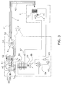
- FIG 2 is an exploded perspective view of the outdoor unit 3 and that FIG 3 is a diagram where air passages through which passes air supplied to the indoors and air discharged to the outdoors are schematically added to a system diagram of a refrigerant circuit with which the air conditioner 1 is equipped.
- the humidity control unit casing 7 houses the moisture adsorbing and humidifying member 51, the heating device 52, the second blowing device 54, the switching damper 53 and the adsorption-use blowing device 55.
- An adsorption-use air blowout opening 7a comprising plural slit-shaped openings is disposed in the front surface of the humidity control unit casing 7.
- An adsorption-use air suction opening 7b and an air supply and discharge opening 7c are disposed in the back surface of the humidity control casing 7.
- the adsorption-use air suction opening 7b is an opening through which passes air that is taken in from the outdoors in order to cause the moisture adsorbing and humidifying member 51 to adsorb moisture.
- the air supply and discharge opening 7c is an opening through which passes air that is taken into the inside of the humidity control unit 4 from the outdoors in order to be sent to the indoor unit 2 during air supplying operation and through which passes air that is taken in from the indoor unit 2 and discharged from the humidity control unit 4 to the outdoors during air discharging operation. It will be noted that the upper portion of the humidity control unit casing 7 is covered by a top plate 56.
- the moisture adsorbing and humidifying member 51 is a ceramic rotor that has a honeycomb structure, and the moisture adsorbing and humidifying member 51 has a generally disc-shaped outer shape.
- the moisture adsorbing and humidifying member 51 is rotatably disposed and is driven to rotate by a rotor drive motor 57 (see FIG. 6 ).
- An adsorbent such as a zeolite, silica gel or alumina is carried on the moisture adsorbing and humidifying member 51.
- This adsorbent, such as a zeolite has the property that it is capable of adsorbing moisture in air into contact therewith and releases the moisture when the adsorbent is heated.
- the heating device 52 is positioned above the moisture adsorbing and humidifying member 51 and is disposed facing the moisture adsorbing and humidifying member 51.
- the heat device 52 can heat the moisture adsorbing and humidifying member 51 by heating air that is sent to the moisture adsorbing and humidifying member 51.
- the second blowing device 54 is disposed on the side of the moisture adsorbing and humidifying member 51 and is a radial fan assembly that generates a flow of air that is taken in from the outdoors and is sent to the indoor unit 2.
- the second blowing device 54 generates a flow of air that leads from the air supply and discharge opening 7c via the moisture adsorbing and humidifying member 51 and the switching damper 53 to the indoors and sends air that has been taken in from the outdoors to the indoor unit 2. Further, the second blowing device 54 can also discharge air that has been taken in from the indoor unit 2 to the outdoors.
- the second blowing device 54 switches these operations when the switching damper 53 switches. As shown in FIG.
- the second blowing device 54 when the second blowing device 54 sends air that has been taken in from the outdoors to the indoor unit 2, the second blowing device 54 sends, to an air supply and discharge duct 58 via the switching damper 53, air that has passed the portion of the moisture adsorbing and humidifying member 51 that faces the heating device 52.
- the air supply and discharge duct 58 is connected to the air supply and discharge hose 6, and the second blowing device 54 supplies air to the indoor unit 2 via the air supply and discharge duct 58 and the air supply and discharge hose 6 (see solid line arrow A1). It will be noted that air that is sent through the air supply and discharge hose 6 to the indoor unit 2 is blown out to the upstream side of a later-described filter 21 inside the indoor unit 2.
- the second blowing device 54 discharges indoor air that has been taken in from the indoor unit 2 to the outdoors, the second blowing device 54 discharges, from the air supply and discharge opening 7c to the outdoors, air that has been sent from the air supply and discharge duct 58 through the air supply and discharge hose 6 (see dotted line arrow A2).
- the switching damper 53 is rotary air flow path switching means disposed below the second blowing device 54.
- the switching damper 53 switches between a first switched state, a second switched state and a third switched state.
- the first switched state air that has been blown out from the second blowing device 54 is supplied to the indoor unit 2 via the air supply and discharge duct 58 through the air supply and discharge hose 6 to the indoor unit 2.
- air flows in the direction of the arrow represented by solid line arrow A1 in FIG 3 , and outdoor air is humidified or not humidified and is supplied through the air supply and discharge hose 6 to the indoor unit 2.
- the path interconnecting the switching damper 53 and the air supply and discharge duct 58 is closed such that the flow of air between the outdoor unit 3 and the indoor unit 2 is cut off.
- the adsorption-use blowing device 55 includes an adsorption-use fan motor 59 and an adsorption-use fan 61 that is driven to rotate by the adsorption-use fan motor 59, and the adsorption-use blowing device 55 generates a flow of air (see solid line arrow A3) that passes the portion of the moisture adsorbing and humidifying member 51 that does not face the heating device 52.
- the adsorption-use blowing device 55 generates a flow of air that is sucked in from the adsorption-use air suction opening 7b, passes the portion of the moisture adsorbing and humidifying member 51 that does not face the heating device 52, passes through an opening in a bellmouth 62, and is discharged from the adsorption-use air blowout opening 7a to the outdoors.
- a compressor 63 As shown in FIG 3 , in the outdoor air conditioning unit 5, there are disposed a compressor 63, a four-way switch valve 64 that is connected to a discharge side of the compressor 63, an accumulator 65 that is connected to a suction side of the compressor 63, an outdoor heat exchanger 66 that is connected to the four-way switch valve 64, and an expansion valve 67 that is connected to the outdoor heat exchanger 66.
- the expansion valve 67 is connected to one end of an indoor heat exchanger 12 via a refrigerant pipe.
- the four-way switch valve 64 is connected to the other end of the indoor heat exchanger 12 via a refrigerant pipe.
- a propeller fan 68 for discharging air after heat exchange by the outdoor heat exchanger 66 to the outside, an outdoor fan motor 69 that drives the propeller fan 68 to rotate, and an electrical components unit 73.
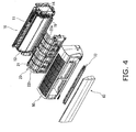
- the indoor unit 2 is a wall-mounted indoor unit that is attached to an indoor wall surface and, as shown in FIG 4 and FIG 5 , includes a body unit 10, a filter unit 20, a front grille 50, a front panel 60 and a dust box 70. It will be noted that FIG 4 is an exploded perspective view of the indoor unit 2 and that FIG 5 is a longitudinal sectional view of the indoor unit 2.
- the body unit 10 includes a bottom frame 11, the indoor heat exchanger 12, a first blowing device 16 (see FIG. 6 ) and an electrical components unit 14, and the like.
- the indoor heat exchanger 12, the first blowing device 16 and the electrical components unit 14 are attached to the bottom frame 11. Further, a blowout opening 15 is disposed in the lower portion of the front surface of the bottom frame 11, and a horizontal flap 17 that guides air that is blown out from the blowout opening 15 is also disposed in the lower portion of the front surface of the bottom frame 11.
- the horizontal flap 17 is driven to rotate by a flap motor 18 (see FIG 6 ) such that the horizontal flap 17 can change the direction in which air is guided and can open and close the blowout opening 15.
- the indoor heat exchanger 12 is configured by plural fins and heat transfer tubes through which a refrigerant flows, and the indoor heat exchanger 12 performs heat exchange with passing air.
- the first blowing device 16 generates a flow of air that is taken in from the indoors, has its temperature regulated by the indoor heat exchanger 12 and is thereafter blown out to the indoors.
- the first blowing device 16 includes a first blowing fan 13 and an indoor fan motor 19.
- the first blowing fan 13 is a cross-flow fan and is driven to rotate by the indoor fan motor 19.
- the first blowing device 16 and the indoor heat exchanger 12 configure a temperature regulating section 22 (see FIG 6 ) that takes in indoor air, regulates its temperature, and blows it out to the indoors.
- the filter unit 20 is attached to the bottom frame 11 of the body unit 10 and is equipped with a filter 21.
- This filter 21 is disposed on the front side (upwind side) of the indoor heat exchanger 12 and removes dirt and dust from the air that has been taken in from the indoors and the outdoors. Thus, the filter 21 prevents dirt and dust flying through the air from dirtying the indoor heat exchanger 12.
- this filter unit 20 includes a take-up mechanism 30, which moves the filter 21 downward in order to perform cleaning to remove dirt and dust adhering to the filter 21, and a motor 26 (see FIG. 6 ). It will be noted that, in a state where the filter 21 is not taken up by the take-up mechanism 30, the filter 21 is disposed so as to cover substantially all of the upwind side of the indoor heat exchanger 12 (see FIG. 5 ).
- the take-up mechanism 30 is, as shown in FIG 5 , disposed on the airflow downstream side of the filter 21 and includes a pair of upper and lower pulleys 31 and 32, an annular belt 33 that is wound around both of the pulleys 31 and 32, and a guide member 42.
- the lower pulley 31 is driven to rotate by the take-up motor 26 to thereby cause the annular belt 33 to circulate.
- the guide member 42 is energized downward and pushes against the annular belt 33 above the pulley 32.
- the front grille 50 is attached to the filter unit 20 so as to cover the filter unit 20, and an upper suction opening 75 is disposed in the top surface of the front grille 50.
- the front panel 60 that covers the front side of the front grille 50 is attached to the front grille 50, and the front panel 60 pivots such that it can open and close a front suction opening 76 that is formed in the front side of the front grille 50.
- the dust box 70 includes the function of performing cleaning of the filter 21.
- the dust box 70 is attached to a position above the blowout opening 15 in the body unit 10.
- This dust box 70 is capable of being detached from the outside without interfering with the front panel 60 in a state where the front panel 60 is closed.
- a rotating brush 71 is disposed in the dust box 70, and this rotating brush 71 presses against and contacts the filter 21 that moves to this portion from the lower side of the filter unit 20.
- the rotating brush 71 is driven to rotate by a brush-use motor 78 (see FIG. 6 ).
- the rotating brush 71, the brush-use motor 78, the take-up mechanism 30 and the take-up motor 26 configure a filter cleaning section 79 (see FIG 6 ) that moves the filter 21 and cleans away dirt and dust adhering to the filter 21.
- a controller 80 shown in FIG 6 is dividedly disposed in the electrical components unit 14 of the indoor unit 2 and the electrical components unit 73 of the outdoor unit 3 and performs, on the basis of instructions from a remote controller 81 and information from various sensors (not shown), various controls of the temperature regulating operation, the humidifying operation, the air supplying and ventilating operation, the air discharging operation and the filter cleaning operation.
- the compressor 63 is driven and the expansion valve 67 is narrowed to a predetermined opening, whereby the refrigerant circulates through the refrigerant circuit and the indoor heat exchanger 12 functions as an evaporator or a condenser.
- the first blowing fan 13 is driven, whereby there is generated a flow of air that is sucked into the inside of the indoor unit 2 from the upper suction opening 75 and the front suction opening 76, passes through the indoor heat exchanger 12, and is blown out to the indoors from the blowout opening 15.
- cooling or heating of the indoors can be performed.
- the front panel 60 is opened by a predetermined opening and the horizontal flap 17 is also opened. The same is also true during the humidifying operation, during the air supplying and ventilating operation and during the air discharging operation.
- the switching damper 53 is switched to the first switched state, and the second blowing device 54 and the adsorption-use fan motor 59 are driven. Further, the heating device 52 is energized.
- outdoor air is taken into the inside of the humidity control unit 4, passes through the air supply and discharge hose 6 and the indoor unit 2, and is supplied to the indoors (see solid line arrow A1 in FIG. 3 ). That is, outdoor air is taken into the inside of the humidity control unit casing 7 from the air supply and discharge opening 7c, passes the moisture adsorbing and humidifying member 51 from downward to upward, is heated in the heating device 52, and thereafter passes the adsorbing and humidifying member 51 from upward to downward. At this time, the moisture that had been adsorbed onto the moisture adsorbing and humidifying member 51 is excited and released into the air from the moisture adsorbing and humidifying member 51.
- the air that has passed the moisture adsorbing and humidifying member 51 passes through the switching damper 53 and the second blowing device 54 and is sent to the air supply and discharge hose 6.
- the air that has been sent to the air supply and discharge hose 6 is sent to the inside of the indoor unit 2.
- the air that has been sent to the inside of the indoor unit 2 passes through the filter 21 and the indoor heat exchanger 12 and is blown out into the indoors from the blowout opening 15.
- the air that has been sent to the indoor unit 2 comes to include the moisture that had been adsorbed onto the moisture adsorbing and humidifying member 51, and thus humidification of the indoors is performed.
- the moisture adsorbing and humidifying member 51 is driven to rotate by the rotor drive motor 57, and moisture adsorption and release are repeated. Thus, it becomes possible to humidify the indoors without supplying water.
- the switching damper 53 is switched to the second switched state and the second blowing device 54 is driven.
- the adsorption-use fan motor 59 is not driven and the heating device 52 is not energized.
- the controller 80 drives the take-up motor 26 to cause the annular belt 33 to move and drives the rotating brush 71 of the dust box 70 to rotate from the state shown in FIG. 5 .
- the filter 21 moves downward together with the annular belt 33, such that the take-up leading end portion travels around the lower pulley 31 and moves up the back side.
- the rotating brush 71 rotates in the opposite direction of the lower pulley 31 and brushes off dirt and dust on the surface of the filter 21.
- the take-up trailing end portion is wound onto the annular belt 33.
- the take-up leading end portion pushes up the guide member 42, passes therebelow, and then moves downward together with the annular belt 33 (see FIG. 7 ).
- the guide member 42 presses against and contacts the surface of the filter 21.
- the take-up trailing end portion contacts the rotating brush 71, and when cleaning of this portion is completed, the controller 80 stops movement of the annular belt 33 and rotational driving of the rotating brush 71 and ends the work of cleaning the filter 21 during outbound movement of the filter 21.
- the controller 80 causes the filter cleaning operation to start when a predetermined filter cleaning operation starting condition has been satisfied.
- the predetermined filter cleaning operation starting condition is that the filter cleaning operation has been instructed in the remote controller 81 or that the cumulative uptime of the temperature regulating operation, the humidifying operation or the air supplying and ventilating operation has reached a predetermined amount of time.
- the controller 80 does not allow the filter cleaning operation by the filter cleaning section 79 to be executed while any of the temperature regulating operation, the humidifying operation and the air supplying and ventilating operation is being executed, even when these filter cleaning operation starting conditions have been satisfied. Filter cleaning operation execution judgment will be described on the basis of the flow of FIG. 8 .
- step S1 it is judged whether or not an automatic cleaning mode is set.
- the automatic cleaning mode is a control mode that executes the filter cleaning operation automatically, even without the user inputting an instruction to the remote controller 81, and can be set beforehand by the remote controller 81.
- step S2 it is judged whether or not there is a cleaning request.
- the cleaning request is set to "there is” when the cumulative uptime of the temperature regulating operation, the humidifying operation or the air supplying and ventilating operation has reached a predetermined amount of time.
- step S1 when it has been judged that the automatic cleaning mode is not set, in step S3, it is judged whether or not there is a cleaning request by manual operation, that is, whether or not a cleaning request has been instructed from the remote controller 81.
- step S4 when there is a cleaning request in the automatic cleaning mode or when there is a cleaning request by manual operation, it is verified, prior to starting the cleaning operation, whether or not the temperature regulating operation is being executed, whether or not the humidifying operation is being executed, and whether or not the air supplying and ventilating operation is being executed (step S4, step S5 and step S6).
- the controller 80 does not allow the filter cleaning operation to start. That is, the filter cleaning operation is not started when at least one of the first blowing device 16 and the second blowing device 54 is being driven.
- the filter cleaning operation is executed in step S7 after the temperature regulating operation or the humidifying operation ends.
- step S8 When the air supplying and ventilating operation is being executed, the air supplying and ventilating operation is temporarily stopped in step S8 and then the filter cleaning operation is started in step S9. It will be noted that, while the air supplying and ventilating operation is stopped for the filter cleaning operation, the fact that the air supplying and ventilating operation is stopped is indicated on the indicator 77. Then, in step S10, it is judged whether or not the filter cleaning operation has been completed, and when the filter cleaning operation has been completed, the air supplying and ventilating operation is resumed in step S 11.
- the filter cleaning operation is not performed not only while the temperature regulating operation is being executed but also while the humidifying operation or the air supplying and ventilating operation is being performed. For this reason, a situation where the humidifying operation or the air supplying and ventilating operation is performed in a state where the indoor heat exchanger 21 is not covered by the filter 21 is prevented. Thus, an increase in the dirtying of the indoor heat exchanger 12 resulting from air that has not passed through the filter 21 passing through the indoor heat exchanger 12 can be prevented.
- the filter cleaning operation when the filter cleaning operation starting condition has been satisfied while the air supplying and ventilating operation is being executed, the filter cleaning operation is started after the controller has caused the air supplying and ventilating operation to stop, and the air supplying and ventilating operation is resumed after the completion of the filter cleaning operation. For this reason, the filter cleaning operation can be performed even when the air supplying and ventilating operation is continuously performed as in constant ventilation.
- filter cleaning operation starting condition another condition may also be used instead of the above-described condition, or another condition may also be added to the above-described condition.
- the indicator 77 is configured by plural LEDs, but the indicator 77 may also be a liquid crystal screen or the like disposed in the indoor unit 2 or in the remote controller 81.
- the wall-mounted indoor unit 2 is used, but an indoor unit that is installed in another way may also be used.
- the filter 21 reciprocally moves and the rotating brush 71 is caused to operate during outbound movement of the filter 21, but the operating method is not limited to these operating methods as long as it is for removing dirt on the filter 21.
- the rotating brush 71 may be caused to operate so as to clean the filter 21 during return movement of the filter 21 also, or the filter 21 may be caused to partially reciprocally move, or the filter 21 may be temporarily stopped and cleaned, or the rotational direction of the rotating brush 71 may be reversed, or the rotating brush 71 may be made to completely operate.
- the drive system of the filter 21 is belt drive reciprocal movement, but another drive system may also be used.
- the present invention has the effect that it can prevent a situation where air ends up flowing through the air conditioner without passing through a filter because of filter cleaning operation, and the present invention is useful as an air conditioner.
Landscapes
- Engineering & Computer Science (AREA)
- Chemical & Material Sciences (AREA)
- Combustion & Propulsion (AREA)
- Mechanical Engineering (AREA)
- General Engineering & Computer Science (AREA)
- Physics & Mathematics (AREA)
- Thermal Sciences (AREA)
- Air Conditioning Control Device (AREA)
- Air Filters, Heat-Exchange Apparatuses, And Housings Of Air-Conditioning Units (AREA)
- Filtering Of Dispersed Particles In Gases (AREA)
Abstract
Description
- The present invention relates to an air conditioner and particularly to an air conditioner that includes a filter cleaning operation function.
- An air conditioner is ordinarily equipped with a filter that removes dirt and dust from air that has been taken in from the indoors, and airflow resistance ends up increasing when dirt and dust adhere to and accumulate on this filter. For this reason, various air conditioners equipped with a function for automatically cleaning the filter have been proposed. One of these is a system that moves the filter and cleans away dirt and dust adhering to the filter (patent document 1).
- Patent Document 1:
JP-A No. 2006-194562 - In the system described above, the filter moves from its original position while filter cleaning operation is being executed, so when temperature regulating operation is performed in this state, there is the potential for air that has been taken in from the indoors to end up flowing through the air conditioner without passing through the filter. In this case, one factor may be dirt and dust adhering to a heat exchanger or the like such that the heat exchanger or the like becomes dirty. For this reason, it is desirable for the filter cleaning operation to not be performed during the temperature regulating operation.
- Meanwhile, there is an air conditioner that includes, separately from a temperature regulating section that performs the temperature regulating operation, a ventilating section that performs ventilating operation that takes in outdoor air and blows it out to the indoors. In this air conditioner, the air that has been taken in from the outdoors by the ventilating section also passes through the filter, whereby dirt and dust are removed.
- However, in this air conditioner, even if it is ensured that the filter cleaning operation is not performed during the temperature regulating operation, there is the potential for the filter cleaning operation to end up being performed during the ventilating operation and for the air that has been taken in from the outdoors to end up flowing through the air conditioner without passing through the filter.
- It is an object of the present invention to provide an air conditioner that can prevent a situation where air ends up flowing through the air conditioner without passing through a filter because of filter cleaning operation.
- An air conditioner according to a first aspect of the present invention comprises a temperature regulating section, a ventilating section, a filter, a filter cleaning section and a controller. The temperature regulating section takes in indoor air, regulates its temperature, and blows it out to the indoors. The ventilating section takes in outdoor air and blows it out to the indoors. The filter removes dirt and dust from the air that has been taken in from the indoors and the outdoors. The filter cleaning section moves the filter and cleans away dirt and dust adhering to the filter. The controller does not allow filter cleaning operation by the filter cleaning section to be executed while temperature regulating operation by the temperature regulating section is being executed and while ventilating operation by the ventilating section is being executed.
- In this air conditioner, the filter cleaning operation by the filter cleaning section is prohibited not only while the temperature regulating operation by the temperature regulating section is being executed but also while the ventilating operation by the ventilating section is being executed. For this reason, a situation where air ends up flowing through the air conditioner without passing through the filter because of the filter cleaning operation can be prevented not only while the temperature regulating operation is being executed by also while the ventilating operation is being executed.
- An air conditioner according to a second aspect of the present invention is the air conditioner according to the first aspect of the present invention, wherein when a predetermined filter cleaning operation starting condition has been satisfied while the temperature regulating operation is stopped and while the ventilating operation is being executed, the controller causes the filter cleaning operation to be started after causing the ventilating operation to stop and then causes the ventilating operation to resume after the completion of the filter cleaning operation.
- In this air conditioner, when the predetermined filter cleaning operation starting condition has been satisfied while the ventilating operation is being executed, the controller causes the ventilating operation to temporarily stop, causes the filter cleaning operation to be performed, and then causes the ventilating operation to resume after the completion of the filter cleaning operation. For this reason, the filter cleaning operation can be performed even when the ventilating operation is continuously performed as in constant ventilating operation.
- An air conditioner according to a third aspect of the present invention is the air conditioner according to the second aspect of the present invention and further comprises an indicator that indicates that the ventilating operation is stopped while the controller is causing the ventilating operation to stop for the filter cleaning operation.
- In this air conditioner, the fact that the ventilating operation is stopped is indicated by the indicator. For this reason, a user can easily know that the ventilating operation is stopped.
- An air conditioner according to a fourth aspect of the present invention is the air conditioner according to any of the first aspect to the third aspect of the present invention, wherein the temperature regulating section includes a first blowing device that generates a flow of air that is taken in from the indoors, has its temperature regulated, and is thereafter blown out to the indoors. Further, the ventilating section includes a second blowing device that generates a flow of air that is taken in from the outdoors and is blown out to the indoors. Additionally, the controller does not allow filter cleaning operation by the filter cleaning section to be executed while the first blowing device is being driven and while the second blowing device is being driven.
- In this air conditioner, the filter cleaning operation is prohibited while the first blowing device is being driven and while the second blowing device is being driven. For this reason, a situation where air ends up flowing through the air conditioner without passing through the filter because of the filter cleaning operation can be prevented not only while the temperature regulating operation is being executed by also while the ventilating operation is being executed.
- In the air conditioner according to the first aspect of the present invention, the filter cleaning operation by the filter cleaning section is prohibited not only while the temperature regulating operation by the temperature regulating section is being executed but also while the ventilating operation by the ventilating section is being executed. For this reason, a situation where air ends up flowing through the air conditioner without passing through the filter because of the filter cleaning operation can be prevented not only while the temperature regulating operation is being executed by also while the ventilating operation is being executed.
- In the air conditioner according to the second aspect of the present invention, when the predetermined filter cleaning operation starting condition has been satisfied while the ventilating operation is being executed, the controller causes the ventilating operation to temporarily stop, causes the filter cleaning operation to be performed, and then causes the ventilating operation to resume after the completion of the filter cleaning operation. For this reason, the filter cleaning operation can be performed even when the ventilating operation is continuously performed as in constant ventilating operation.
- In the air conditioner according to the third aspect of the present invention, the fact that the ventilating operation is stopped is indicated by the indicator. For this reason, a user can easily know that the ventilating operation is stopped.
- In the air conditioner according to the fourth aspect of the present invention, the filter cleaning operation is prohibited while the first blowing device is being driven and while the second blowing device is being driven. For this reason, a situation where air ends up flowing through the air conditioner without passing through the filter because of the filter cleaning operation can be prevented not only while the temperature regulating operation is being executed by also while the ventilating operation is being executed.
-
-
FIG 1 is an external view of an air conditioner. -
FIG 2 is an exploded perspective view of an outdoor unit. -
FIG 3 is a refrigerant circuit diagram of the air conditioner. -
FIG 4 is an exploded perspective view of an indoor unit. -
FIG 5 is a side sectional view of the indoor unit. -
FIG 6 is a block diagram showing the configuration of the air conditioner. -
FIG 7 is a diagram showing a state of a filter during filter cleaning operation. -
FIG 8 is a filter cleaning operation execution judgment flowchart. -
- 1
- Air Conditioner
- 4
- Humidity Control Unit (Ventilating Section)
- 16
- First Blowing Device
- 22
- Temperature Regulating Section
- 21
- Filter
- 54
- Second Blowing Device
- 77
- Indicator
- 79
- Filter Cleaning Section
- 80
- Controller
-
FIG 1 shows the exterior of anair conditioner 1 according to an embodiment of the present invention. - This
air conditioner 1 is divided into and configured by anindoor unit 2 that is installed indoors and anoutdoor unit 3 that is installed outdoors, and theair conditioner 1 can perform cooling and heating of the indoors. - Further, the
outdoor unit 3 includes an outdoorair conditioning unit 5 and ahumidity control unit 4 that is placed on the outdoorair conditioning unit 5. As described later, thehumidity control unit 4 can supply outdoor air to the indoors and can discharge indoor air to the outdoors. Between theoutdoor unit 3 and theindoor unit 2, there is disposed an air supply anddischarge hose 6 that is used when supplying outdoor air and humidity-controlled air from thehumidity control unit 4 to theindoor unit 2 and when discharging indoor air to the outdoors. - The
humidity control unit 4 can perform air discharging operation that discharges air that has been taken in from the indoors to the outdoors and air supplying operation that supplies air that has been taken in from the outdoors to the indoors. Further, in the air supplying operation, there are humidifying operation that humidifies air that has been taken in from the outdoors and supplies the humidified air to the indoors and air supplying and ventilating operation that supplies air that has been taken in from the outdoors to the indoors without humidifying that air. That is, thehumidity control unit 4 can function as a ventilating section that takes in outdoor air and blows it out to the indoors. Thehumidity control unit 4 is, as shown inFIG. 2 andFIG 3 , equipped with a humidity control unit casing 7, a moisture adsorbing and humidifyingmember 51, aheating device 52, a switchingdamper 53, asecond blowing device 54 and an adsorption-use blowing device 55. It will be noted thatFIG 2 is an exploded perspective view of theoutdoor unit 3 and thatFIG 3 is a diagram where air passages through which passes air supplied to the indoors and air discharged to the outdoors are schematically added to a system diagram of a refrigerant circuit with which theair conditioner 1 is equipped. - The humidity control unit casing 7 houses the moisture adsorbing and humidifying
member 51, theheating device 52, thesecond blowing device 54, the switchingdamper 53 and the adsorption-use blowing device 55. - An adsorption-use
air blowout opening 7a comprising plural slit-shaped openings is disposed in the front surface of the humidity control unit casing 7. An adsorption-useair suction opening 7b and an air supply and discharge opening 7c are disposed in the back surface of the humidity control casing 7. The adsorption-useair suction opening 7b is an opening through which passes air that is taken in from the outdoors in order to cause the moisture adsorbing and humidifyingmember 51 to adsorb moisture. The air supply and discharge opening 7c is an opening through which passes air that is taken into the inside of thehumidity control unit 4 from the outdoors in order to be sent to theindoor unit 2 during air supplying operation and through which passes air that is taken in from theindoor unit 2 and discharged from thehumidity control unit 4 to the outdoors during air discharging operation. It will be noted that the upper portion of the humidity control unit casing 7 is covered by atop plate 56. - The moisture adsorbing and humidifying
member 51 is a ceramic rotor that has a honeycomb structure, and the moisture adsorbing and humidifyingmember 51 has a generally disc-shaped outer shape. The moisture adsorbing and humidifyingmember 51 is rotatably disposed and is driven to rotate by a rotor drive motor 57 (seeFIG. 6 ). An adsorbent such as a zeolite, silica gel or alumina is carried on the moisture adsorbing and humidifyingmember 51. This adsorbent, such as a zeolite, has the property that it is capable of adsorbing moisture in air into contact therewith and releases the moisture when the adsorbent is heated. - The
heating device 52 is positioned above the moisture adsorbing and humidifyingmember 51 and is disposed facing the moisture adsorbing and humidifyingmember 51. Theheat device 52 can heat the moisture adsorbing and humidifyingmember 51 by heating air that is sent to the moisture adsorbing and humidifyingmember 51. - The
second blowing device 54 is disposed on the side of the moisture adsorbing and humidifyingmember 51 and is a radial fan assembly that generates a flow of air that is taken in from the outdoors and is sent to theindoor unit 2. Thesecond blowing device 54 generates a flow of air that leads from the air supply and discharge opening 7c via the moisture adsorbing and humidifyingmember 51 and the switchingdamper 53 to the indoors and sends air that has been taken in from the outdoors to theindoor unit 2. Further, thesecond blowing device 54 can also discharge air that has been taken in from theindoor unit 2 to the outdoors. Thesecond blowing device 54 switches these operations when the switchingdamper 53 switches. As shown inFIG. 3 , when thesecond blowing device 54 sends air that has been taken in from the outdoors to theindoor unit 2, thesecond blowing device 54 sends, to an air supply anddischarge duct 58 via the switchingdamper 53, air that has passed the portion of the moisture adsorbing and humidifyingmember 51 that faces theheating device 52. The air supply anddischarge duct 58 is connected to the air supply anddischarge hose 6, and thesecond blowing device 54 supplies air to theindoor unit 2 via the air supply anddischarge duct 58 and the air supply and discharge hose 6 (see solid line arrow A1). It will be noted that air that is sent through the air supply anddischarge hose 6 to theindoor unit 2 is blown out to the upstream side of a later-describedfilter 21 inside theindoor unit 2. Further, when thesecond blowing device 54 discharges indoor air that has been taken in from theindoor unit 2 to the outdoors, thesecond blowing device 54 discharges, from the air supply and discharge opening 7c to the outdoors, air that has been sent from the air supply anddischarge duct 58 through the air supply and discharge hose 6 (see dotted line arrow A2). - The switching
damper 53 is rotary air flow path switching means disposed below thesecond blowing device 54. The switchingdamper 53 switches between a first switched state, a second switched state and a third switched state. - In the first switched state, air that has been blown out from the
second blowing device 54 is supplied to theindoor unit 2 via the air supply anddischarge duct 58 through the air supply anddischarge hose 6 to theindoor unit 2. Thus, in the first switched state, air flows in the direction of the arrow represented by solid line arrow A1 inFIG 3 , and outdoor air is humidified or not humidified and is supplied through the air supply anddischarge hose 6 to theindoor unit 2. - In the second switched state, air flows in the direction of the arrow represented by dotted line arrow A2 in
FIG. 3 , and air that has passed from theindoor unit 2 through the air supply anddischarge hose 6 and the air supply anddischarge duct 58 is discharged from thesecond blowing device 54 via the air supply and discharge opening 7c to the outdoors. - In the third switched state, the path interconnecting the switching
damper 53 and the air supply anddischarge duct 58 is closed such that the flow of air between theoutdoor unit 3 and theindoor unit 2 is cut off. - The adsorption-
use blowing device 55 includes an adsorption-use fan motor 59 and an adsorption-use fan 61 that is driven to rotate by the adsorption-use fan motor 59, and the adsorption-use blowing device 55 generates a flow of air (see solid line arrow A3) that passes the portion of the moisture adsorbing and humidifyingmember 51 that does not face theheating device 52. That is, the adsorption-use blowing device 55 generates a flow of air that is sucked in from the adsorption-useair suction opening 7b, passes the portion of the moisture adsorbing and humidifyingmember 51 that does not face theheating device 52, passes through an opening in abellmouth 62, and is discharged from the adsorption-useair blowout opening 7a to the outdoors. - As shown in
FIG 3 , in the outdoorair conditioning unit 5, there are disposed acompressor 63, a four-way switch valve 64 that is connected to a discharge side of thecompressor 63, anaccumulator 65 that is connected to a suction side of thecompressor 63, anoutdoor heat exchanger 66 that is connected to the four-way switch valve 64, and anexpansion valve 67 that is connected to theoutdoor heat exchanger 66. Theexpansion valve 67 is connected to one end of anindoor heat exchanger 12 via a refrigerant pipe. Further, the four-way switch valve 64 is connected to the other end of theindoor heat exchanger 12 via a refrigerant pipe. - Further, inside the outdoor
air conditioning unit 5, there are also disposed apropeller fan 68 for discharging air after heat exchange by theoutdoor heat exchanger 66 to the outside, anoutdoor fan motor 69 that drives thepropeller fan 68 to rotate, and anelectrical components unit 73. - The
indoor unit 2 is a wall-mounted indoor unit that is attached to an indoor wall surface and, as shown inFIG 4 andFIG 5 , includes abody unit 10, afilter unit 20, afront grille 50, afront panel 60 and adust box 70. It will be noted thatFIG 4 is an exploded perspective view of theindoor unit 2 and thatFIG 5 is a longitudinal sectional view of theindoor unit 2. - The
body unit 10 includes abottom frame 11, theindoor heat exchanger 12, a first blowing device 16 (seeFIG. 6 ) and anelectrical components unit 14, and the like. - The
indoor heat exchanger 12, thefirst blowing device 16 and theelectrical components unit 14 are attached to thebottom frame 11. Further, ablowout opening 15 is disposed in the lower portion of the front surface of thebottom frame 11, and a horizontal flap 17 that guides air that is blown out from theblowout opening 15 is also disposed in the lower portion of the front surface of thebottom frame 11. The horizontal flap 17 is driven to rotate by a flap motor 18 (seeFIG 6 ) such that the horizontal flap 17 can change the direction in which air is guided and can open and close theblowout opening 15. - The
indoor heat exchanger 12 is configured by plural fins and heat transfer tubes through which a refrigerant flows, and theindoor heat exchanger 12 performs heat exchange with passing air. - The
first blowing device 16 generates a flow of air that is taken in from the indoors, has its temperature regulated by theindoor heat exchanger 12 and is thereafter blown out to the indoors. Thefirst blowing device 16 includes a first blowingfan 13 and anindoor fan motor 19. The first blowingfan 13 is a cross-flow fan and is driven to rotate by theindoor fan motor 19. - It will be noted that the
first blowing device 16 and theindoor heat exchanger 12 configure a temperature regulating section 22 (seeFIG 6 ) that takes in indoor air, regulates its temperature, and blows it out to the indoors. - The
filter unit 20 is attached to thebottom frame 11 of thebody unit 10 and is equipped with afilter 21. Thisfilter 21 is disposed on the front side (upwind side) of theindoor heat exchanger 12 and removes dirt and dust from the air that has been taken in from the indoors and the outdoors. Thus, thefilter 21 prevents dirt and dust flying through the air from dirtying theindoor heat exchanger 12. Further, thisfilter unit 20 includes a take-upmechanism 30, which moves thefilter 21 downward in order to perform cleaning to remove dirt and dust adhering to thefilter 21, and a motor 26 (seeFIG. 6 ). It will be noted that, in a state where thefilter 21 is not taken up by the take-upmechanism 30, thefilter 21 is disposed so as to cover substantially all of the upwind side of the indoor heat exchanger 12 (seeFIG. 5 ). - The take-up
mechanism 30 is, as shown inFIG 5 , disposed on the airflow downstream side of thefilter 21 and includes a pair of upper andlower pulleys annular belt 33 that is wound around both of thepulleys guide member 42. Thelower pulley 31 is driven to rotate by the take-upmotor 26 to thereby cause theannular belt 33 to circulate. Theguide member 42 is energized downward and pushes against theannular belt 33 above thepulley 32. - As shown in
FIG 4 , thefront grille 50 is attached to thefilter unit 20 so as to cover thefilter unit 20, and an upper suction opening 75 is disposed in the top surface of thefront grille 50. Further, thefront panel 60 that covers the front side of thefront grille 50 is attached to thefront grille 50, and thefront panel 60 pivots such that it can open and close a front suction opening 76 that is formed in the front side of thefront grille 50. - Further, an indicator 77 (see
FIG 1 andFIG 6 ) that indicates the operating condition of theindoor unit 2 is disposed in thefront grille 50. Theindicator 77 is disposed so as to be viewable from the front of theindoor unit 2. Theindicator 77 comprises plural LEDs and indicates the operating condition of theindoor unit 2 by whether or not the LEDs are lighted. - The
dust box 70 includes the function of performing cleaning of thefilter 21. In the lower portion of thefront panel 60, thedust box 70 is attached to a position above theblowout opening 15 in thebody unit 10. Thisdust box 70 is capable of being detached from the outside without interfering with thefront panel 60 in a state where thefront panel 60 is closed. Further, a rotatingbrush 71 is disposed in thedust box 70, and this rotatingbrush 71 presses against and contacts thefilter 21 that moves to this portion from the lower side of thefilter unit 20. Additionally, during cleaning, the rotatingbrush 71 is driven to rotate by a brush-use motor 78 (seeFIG. 6 ). The rotatingbrush 71, the brush-use motor 78, the take-upmechanism 30 and the take-upmotor 26 configure a filter cleaning section 79 (seeFIG 6 ) that moves thefilter 21 and cleans away dirt and dust adhering to thefilter 21. - A
controller 80 shown inFIG 6 is dividedly disposed in theelectrical components unit 14 of theindoor unit 2 and theelectrical components unit 73 of theoutdoor unit 3 and performs, on the basis of instructions from aremote controller 81 and information from various sensors (not shown), various controls of the temperature regulating operation, the humidifying operation, the air supplying and ventilating operation, the air discharging operation and the filter cleaning operation. - Below, operation during each air conditioning operation will be described.
- During the temperature regulating operation, the
compressor 63 is driven and theexpansion valve 67 is narrowed to a predetermined opening, whereby the refrigerant circulates through the refrigerant circuit and theindoor heat exchanger 12 functions as an evaporator or a condenser. Further, the first blowingfan 13 is driven, whereby there is generated a flow of air that is sucked into the inside of theindoor unit 2 from the upper suction opening 75 and the front suction opening 76, passes through theindoor heat exchanger 12, and is blown out to the indoors from theblowout opening 15. Thus, cooling or heating of the indoors can be performed. - It will be noted that, during the temperature regulating operation, the
front panel 60 is opened by a predetermined opening and the horizontal flap 17 is also opened. The same is also true during the humidifying operation, during the air supplying and ventilating operation and during the air discharging operation. - During the humidifying operation, the switching
damper 53 is switched to the first switched state, and thesecond blowing device 54 and the adsorption-use fan motor 59 are driven. Further, theheating device 52 is energized. - When the adsorption-
use fan motor 59 is driven, outdoor air is taken into the inside of thehumidity control unit 4 and is discharged to the outdoors (see solid line arrow A3 inFIG. 3 ). That is, air from the outdoors is taken into the inside of the humidity control unit casing 7 from the adsorption-useair suction opening 7b. The air that has entered the inside of the humidity control unit casing 7 passes the position of the moisture adsorbing and humidifyingmember 51 that does not face theheating device 52. At this time, the moisture adsorbing and humidifyingmember 51 adsorbs moisture from the air that passes the adsorption position of the moisture adsorbing and humidifyingmember 51. The air that has passed the moisture adsorbing and humidifyingmember 51 doubles back downward and is discharged to the outside of theoutdoor unit 3 from the adsorption-useair blowout opening 7a. - When the
second blowing device 54 is driven, outdoor air is taken into the inside of thehumidity control unit 4, passes through the air supply anddischarge hose 6 and theindoor unit 2, and is supplied to the indoors (see solid line arrow A1 inFIG. 3 ). That is, outdoor air is taken into the inside of the humidity control unit casing 7 from the air supply and discharge opening 7c, passes the moisture adsorbing and humidifyingmember 51 from downward to upward, is heated in theheating device 52, and thereafter passes the adsorbing and humidifyingmember 51 from upward to downward. At this time, the moisture that had been adsorbed onto the moisture adsorbing and humidifyingmember 51 is excited and released into the air from the moisture adsorbing and humidifyingmember 51. The air that has passed the moisture adsorbing and humidifyingmember 51 passes through the switchingdamper 53 and thesecond blowing device 54 and is sent to the air supply anddischarge hose 6. The air that has been sent to the air supply anddischarge hose 6 is sent to the inside of theindoor unit 2. The air that has been sent to the inside of theindoor unit 2 passes through thefilter 21 and theindoor heat exchanger 12 and is blown out into the indoors from theblowout opening 15. The air that has been sent to theindoor unit 2 comes to include the moisture that had been adsorbed onto the moisture adsorbing and humidifyingmember 51, and thus humidification of the indoors is performed. - It will be noted that the moisture adsorbing and humidifying
member 51 is driven to rotate by therotor drive motor 57, and moisture adsorption and release are repeated. Thus, it becomes possible to humidify the indoors without supplying water. - When the air supplying and ventilating operation is performed, operation that is the same as the above-described humidifying operation is performed without the adsorption-
use fan motor 59 being actuated and without theheating device 52 being energized. Thus, air that has been taken in from the outdoors travels the same path as described above and is sent to theindoor unit 2 without being humidified. - During the air discharging operation, the switching
damper 53 is switched to the second switched state and thesecond blowing device 54 is driven. The adsorption-use fan motor 59 is not driven and theheating device 52 is not energized. - When the
second blowing device 54 is driven, indoor air that has been taken in from theindoor unit 2 is taken into the inside of thehumidity control unit 4 through the air supply anddischarge hose 6 and flows in the opposite direction as during the above-described humidifying operation, whereby the air is discharged to the outdoors (see wavy line arrow A2 inFIG. 3 ). That is, the air that has been taken into the inside of thehumidity control unit 4 from the air supply anddischarge duct 58 passes through the switchingdamper 53 and thesecond blowing device 54, passes the moisture adsorbing and humidifyingmember 51 from downward to upward, passes through theheating device 52, passes the moisture adsorbing and humidifyingmember 51 from upward to downward, and is discharged to the outdoors from the air supply and discharge opening 7c. - During the temperature regulating operation, during the humidifying operation, during the air supplying and ventilating operation, and during the air discharging operation, operation is performed in a state where the
filter 21 is positioned in the normal position shown inFIG 5 . When such operation is performed, dirt and dust adhere to thefilter 21, so when a predetermined condition has been satisfied, the filter cleaning operation that automatically removes the dirt and dust adhering to thefilter 21 is performed. Below, operation during this filter cleaning operation will be described with reference toFIG. 5 to FIG 7 . It will be noted that, for the convenience of description, in the state shown inFIG 5 (a state during normal operation), the lower portion of thefilter 21 will be called a take-up leading end portion and the upper end portion of thefilter 21 will be called a take-up trailing end portion. - First, the
controller 80 drives the take-upmotor 26 to cause theannular belt 33 to move and drives the rotatingbrush 71 of thedust box 70 to rotate from the state shown inFIG. 5 . When this happens, thefilter 21 moves downward together with theannular belt 33, such that the take-up leading end portion travels around thelower pulley 31 and moves up the back side. At this time, the rotatingbrush 71 rotates in the opposite direction of thelower pulley 31 and brushes off dirt and dust on the surface of thefilter 21. Then, before the take-up leading end portion reaches the position of theguide member 42, the take-up trailing end portion is wound onto theannular belt 33. Then, when the take-up leading end portion reaches the position of theguide member 42, the take-up leading end portion pushes up theguide member 42, passes therebelow, and then moves downward together with the annular belt 33 (seeFIG. 7 ). In this state, theguide member 42 presses against and contacts the surface of thefilter 21. Then, the take-up trailing end portion contacts the rotatingbrush 71, and when cleaning of this portion is completed, thecontroller 80 stops movement of theannular belt 33 and rotational driving of the rotatingbrush 71 and ends the work of cleaning thefilter 21 during outbound movement of thefilter 21. - Next, return movement is performed, but at this time, the moving direction of the
annular belt 33 and the rotational direction of the rotatingbrush 71 are the opposite of what they were during the above-described outbound movement of thefilter 21, and the rotatingbrush 71 remains stopped. In this case, because of the movement of theannular belt 33, the take-up leading end portion passes the position of theguide member 42, and theguide member 42 returns to the state where it presses against and contacts the surface of theannular belt 33. Next, the take-up trailing end portion separates from theannular belt 33. This is because theannular belt 33 curves toward the back side due to theupper pulley 32, but thefilter 21 tries to maintain its erect state due to its own rigidity, so the distance between both gradually becomes wider and, as a result, thefilter 21 separates from the surface of theannular belt 33. At this time, even if the take-up trailing end portion were to not completely separate from theannular belt 33 such that the take-up trailing end portion tries to follow the curvature of theannular belt 33, a stripping force in the direction that strips the take-up trailing end portion from theannular belt 33 acts on the take-up trailing end portion from theguide member 42 because theguide member 42 pushes against and contacts the surface of theannular belt 33, and thus the take-up trailing end portion reliably separates from theannular belt 33. Then, when thefilter 21 returns to its normal use position shown inFIG 5 , thefilter 21 completes its return movement. - It will be noted that, during this filter cleaning operation, the
front panel 60 and the horizontal flap 17 are both closed. - In this
air conditioner 1, thecontroller 80 causes the filter cleaning operation to start when a predetermined filter cleaning operation starting condition has been satisfied. The predetermined filter cleaning operation starting condition is that the filter cleaning operation has been instructed in theremote controller 81 or that the cumulative uptime of the temperature regulating operation, the humidifying operation or the air supplying and ventilating operation has reached a predetermined amount of time. However, thecontroller 80 does not allow the filter cleaning operation by thefilter cleaning section 79 to be executed while any of the temperature regulating operation, the humidifying operation and the air supplying and ventilating operation is being executed, even when these filter cleaning operation starting conditions have been satisfied. Filter cleaning operation execution judgment will be described on the basis of the flow ofFIG. 8 . - First, in step S1, it is judged whether or not an automatic cleaning mode is set. The automatic cleaning mode is a control mode that executes the filter cleaning operation automatically, even without the user inputting an instruction to the
remote controller 81, and can be set beforehand by theremote controller 81. - When the automatic cleaning mode is set, in step S2, it is judged whether or not there is a cleaning request. The cleaning request is set to "there is" when the cumulative uptime of the temperature regulating operation, the humidifying operation or the air supplying and ventilating operation has reached a predetermined amount of time.
- On the other hand, in step S1, when it has been judged that the automatic cleaning mode is not set, in step S3, it is judged whether or not there is a cleaning request by manual operation, that is, whether or not a cleaning request has been instructed from the
remote controller 81. - Then, when there is a cleaning request in the automatic cleaning mode or when there is a cleaning request by manual operation, it is verified, prior to starting the cleaning operation, whether or not the temperature regulating operation is being executed, whether or not the humidifying operation is being executed, and whether or not the air supplying and ventilating operation is being executed (step S4, step S5 and step S6). Here, when any of the temperature regulating operation, the humidifying operation and the air supplying and ventilating operation is being executed, the
controller 80 does not allow the filter cleaning operation to start. That is, the filter cleaning operation is not started when at least one of thefirst blowing device 16 and thesecond blowing device 54 is being driven. - When the temperature regulating operation or the humidifying operation is being executed, the filter cleaning operation is executed in step S7 after the temperature regulating operation or the humidifying operation ends.
- When the air supplying and ventilating operation is being executed, the air supplying and ventilating operation is temporarily stopped in step S8 and then the filter cleaning operation is started in step S9. It will be noted that, while the air supplying and ventilating operation is stopped for the filter cleaning operation, the fact that the air supplying and ventilating operation is stopped is indicated on the
indicator 77. Then, in step S10, it is judged whether or not the filter cleaning operation has been completed, and when the filter cleaning operation has been completed, the air supplying and ventilating operation is resumed instep S 11. - In this
air conditioner 1, the filter cleaning operation is not performed not only while the temperature regulating operation is being executed but also while the humidifying operation or the air supplying and ventilating operation is being performed. For this reason, a situation where the humidifying operation or the air supplying and ventilating operation is performed in a state where theindoor heat exchanger 21 is not covered by thefilter 21 is prevented. Thus, an increase in the dirtying of theindoor heat exchanger 12 resulting from air that has not passed through thefilter 21 passing through theindoor heat exchanger 12 can be prevented. - In this
air conditioner 1, when the filter cleaning operation starting condition has been satisfied while the air supplying and ventilating operation is being executed, the filter cleaning operation is started after the controller has caused the air supplying and ventilating operation to stop, and the air supplying and ventilating operation is resumed after the completion of the filter cleaning operation. For this reason, the filter cleaning operation can be performed even when the air supplying and ventilating operation is continuously performed as in constant ventilation. - Further, when the air supplying and ventilating operation is stopped for the filter cleaning operation, this is indicated on the
indicator 77. For this reason, the user can be notified that the reason the air supplying and ventilating operation is stopped is for the filter cleaning operation and not because of a malfunction. - As for the filter cleaning operation starting condition, another condition may also be used instead of the above-described condition, or another condition may also be added to the above-described condition.
- In the above-described embodiment, the
indicator 77 is configured by plural LEDs, but theindicator 77 may also be a liquid crystal screen or the like disposed in theindoor unit 2 or in theremote controller 81. - In the above-described embodiment, the wall-mounted
indoor unit 2 is used, but an indoor unit that is installed in another way may also be used. - In the above-described embodiment, the
filter 21 reciprocally moves and the rotatingbrush 71 is caused to operate during outbound movement of thefilter 21, but the operating method is not limited to these operating methods as long as it is for removing dirt on thefilter 21. For example, the rotatingbrush 71 may be caused to operate so as to clean thefilter 21 during return movement of thefilter 21 also, or thefilter 21 may be caused to partially reciprocally move, or thefilter 21 may be temporarily stopped and cleaned, or the rotational direction of the rotatingbrush 71 may be reversed, or the rotatingbrush 71 may be made to completely operate. - In the above-described embodiment, the drive system of the
filter 21 is belt drive reciprocal movement, but another drive system may also be used. - The present invention has the effect that it can prevent a situation where air ends up flowing through the air conditioner without passing through a filter because of filter cleaning operation, and the present invention is useful as an air conditioner.
Claims (4)
- An air conditioner comprising:a temperature regulating section (22) that takes in indoor air, regulates its temperature, and blows it out to the indoors;a ventilating section (4) that takes in outdoor air and blows it out to the indoors;a filter (21) that removes dirt and dust from the air that has been taken in from the indoors and the outdoors;a filter cleaning section (79) that moves the filter (21) and cleans away dirt and dust adhering to the filter (21); anda controller (80) that does not allow filter cleaning operation by the filter cleaning section (79) to be executed while temperature regulating operation by the temperature regulating section (22) is being executed and while ventilating operation by the ventilating section (4) is being executed.
- The air conditioner (1) according to claim 1, wherein when a predetermined filter cleaning operation starting condition has been satisfied while the temperature regulating operation is stopped and the ventilating operation is being executed, the controller (80) causes the filter cleaning operation to be started after causing the ventilating operation to stop and then causes the ventilating operation to resume after the completion of the filter cleaning operation.
- The air conditioner (1) according to claim 2, further comprising an indicator (77) that indicates that the ventilating operation is stopped while the controller (80) is causing the ventilating operation to stop for the filter cleaning operation.
- The air conditioner (1) according to any of claims 1 to 3, wherein
the temperature regulating section (22) includes a first blowing device (16) that generates a flow of air that is taken in from the indoors, has its temperature regulated, and is thereafter blown out to the indoors,
the ventilating section (4) includes a second blowing device (54) that generates a flow of air that is taken in from the outdoors and is blown out to the indoors, and
the controller (80) does not allow filter cleaning operation by the filter cleaning section (79) to be executed while the first blowing device (16) is being driven and while the second blowing device (54) is being driven.
Applications Claiming Priority (2)
| Application Number | Priority Date | Filing Date | Title |
|---|---|---|---|
| JP2006309825A JP4240115B2 (en) | 2006-11-16 | 2006-11-16 | Air conditioner |
| PCT/JP2007/072088 WO2008059871A1 (en) | 2006-11-16 | 2007-11-14 | Air conditioner |
Publications (2)
| Publication Number | Publication Date |
|---|---|
| EP2088382A1 true EP2088382A1 (en) | 2009-08-12 |
| EP2088382A4 EP2088382A4 (en) | 2016-06-01 |
Family
ID=39401675
Family Applications (1)
| Application Number | Title | Priority Date | Filing Date |
|---|---|---|---|
| EP07831818.5A Withdrawn EP2088382A4 (en) | 2006-11-16 | 2007-11-14 | AIR CONDITIONER |
Country Status (5)
| Country | Link |
|---|---|
| EP (1) | EP2088382A4 (en) |
| JP (1) | JP4240115B2 (en) |
| KR (1) | KR20090085657A (en) |
| CN (1) | CN101535734B (en) |
| WO (1) | WO2008059871A1 (en) |
Families Citing this family (16)
| Publication number | Priority date | Publication date | Assignee | Title |
|---|---|---|---|---|
| JP4935774B2 (en) * | 2008-07-18 | 2012-05-23 | ダイキン工業株式会社 | Ceiling-mounted air conditioner |
| JP5062114B2 (en) * | 2008-09-09 | 2012-10-31 | ダイキン工業株式会社 | Air conditioner indoor unit |
| JP5213608B2 (en) * | 2008-09-26 | 2013-06-19 | 三菱電機株式会社 | Filter cleaning device and air conditioner |
| JP5353269B2 (en) * | 2009-01-30 | 2013-11-27 | ダイキン工業株式会社 | Air conditioning system |
| JP5239914B2 (en) * | 2009-01-30 | 2013-07-17 | ダイキン工業株式会社 | Air conditioning system |
| JP5845387B2 (en) * | 2011-01-17 | 2016-01-20 | パナソニックIpマネジメント株式会社 | Filter automatic cleaning device, air cleaning device using the same, and air cleaning device with humidification function |
| JP5636324B2 (en) * | 2011-03-31 | 2014-12-03 | 日立アプライアンス株式会社 | Air conditioner |
| JP5772890B2 (en) * | 2013-07-02 | 2015-09-02 | 三菱電機株式会社 | Air purifier |
| CN104654515B (en) * | 2013-11-21 | 2017-06-20 | 珠海格力电器股份有限公司 | Air conditioner dust accumulation detection method and system |
| JP6299715B2 (en) * | 2015-09-30 | 2018-03-28 | ダイキン工業株式会社 | Air conditioning indoor unit |
| JP7436784B2 (en) * | 2019-09-30 | 2024-02-22 | ダイキン工業株式会社 | air conditioner |
| JP7064153B2 (en) * | 2020-08-03 | 2022-05-10 | ダイキン工業株式会社 | Air conditioning indoor unit |
| JP7227521B1 (en) | 2021-08-31 | 2023-02-22 | ダイキン工業株式会社 | air conditioner |
| JP7148690B1 (en) | 2021-08-31 | 2022-10-05 | ダイキン工業株式会社 | air conditioner |
| WO2023124492A1 (en) * | 2021-12-31 | 2023-07-06 | 海信(广东)空调有限公司 | Outdoor unit |
| JP7507206B2 (en) * | 2022-08-26 | 2024-06-27 | 日立ジョンソンコントロールズ空調株式会社 | Air conditioners |
Family Cites Families (8)
| Publication number | Priority date | Publication date | Assignee | Title |
|---|---|---|---|---|
| JP3742930B2 (en) * | 2002-12-09 | 2006-02-08 | ダイキン工業株式会社 | Air conditioner |
| JP4006394B2 (en) * | 2003-12-09 | 2007-11-14 | 日立アプライアンス株式会社 | Air conditioner |
| JP2005241093A (en) * | 2004-02-25 | 2005-09-08 | Matsushita Electric Ind Co Ltd | Ventilation blower |
| JP2006052876A (en) * | 2004-08-10 | 2006-02-23 | Fujitsu General Ltd | Air conditioner |
| JP4573026B2 (en) * | 2004-08-26 | 2010-11-04 | 株式会社富士通ゼネラル | Air conditioner |
| JP4479472B2 (en) * | 2004-11-08 | 2010-06-09 | パナソニック株式会社 | Air conditioner |
| JP4586973B2 (en) | 2005-01-17 | 2010-11-24 | 株式会社富士通ゼネラル | Air conditioner |
| JP2006170613A (en) * | 2006-03-17 | 2006-06-29 | Fujitsu General Ltd | Air conditioner |
-
2006
- 2006-11-16 JP JP2006309825A patent/JP4240115B2/en not_active Expired - Fee Related
-
2007
- 2007-11-14 WO PCT/JP2007/072088 patent/WO2008059871A1/en not_active Ceased
- 2007-11-14 EP EP07831818.5A patent/EP2088382A4/en not_active Withdrawn
- 2007-11-14 KR KR1020097011164A patent/KR20090085657A/en not_active Ceased
- 2007-11-14 CN CN2007800423911A patent/CN101535734B/en active Active
Non-Patent Citations (1)
| Title |
|---|
| See references of WO2008059871A1 * |
Also Published As
| Publication number | Publication date |
|---|---|
| CN101535734A (en) | 2009-09-16 |
| CN101535734B (en) | 2012-06-06 |
| JP2008122047A (en) | 2008-05-29 |
| EP2088382A4 (en) | 2016-06-01 |
| JP4240115B2 (en) | 2009-03-18 |
| KR20090085657A (en) | 2009-08-07 |
| WO2008059871A1 (en) | 2008-05-22 |
Similar Documents
| Publication | Publication Date | Title |
|---|---|---|
| WO2008059871A1 (en) | Air conditioner | |
| KR100917725B1 (en) | Indoor unit of air-conditioner | |
| JP3608548B2 (en) | Ventilator and air conditioner | |
| WO2008072541A1 (en) | Air-conditioner | |
| JP2008145090A (en) | Air conditioner indoor unit | |
| JP4648208B2 (en) | Air conditioner indoor unit | |
| TW202221261A (en) | dehumidifier | |
| JPWO2010073858A1 (en) | Air conditioner indoor unit | |
| JP4589243B2 (en) | Air conditioner indoor unit | |
| CN117813468B (en) | Air conditioning unit | |
| JP2008175512A (en) | Air conditioner indoor unit | |
| JP4083496B2 (en) | Air conditioner indoor unit | |
| JP4083495B2 (en) | Air conditioner indoor unit | |
| JP4683056B2 (en) | Air conditioner indoor unit | |
| KR200274979Y1 (en) | Fixed heat exchanging ventilation device unioned with window | |
| JP2012097999A (en) | Air conditioner | |
| JP2009085541A (en) | Air conditioner indoor unit | |
| JP4064753B2 (en) | Air conditioner indoor unit | |
| JP3858914B2 (en) | Ventilator and air conditioner | |
| TW202235782A (en) | dehumidifier | |
| HK40090311B (en) | Dehumidifier | |
| HK40090311A (en) | Dehumidifier | |
| JPH1061977A (en) | Humidifier |
Legal Events
| Date | Code | Title | Description |
|---|---|---|---|
| PUAI | Public reference made under article 153(3) epc to a published international application that has entered the european phase |
Free format text: ORIGINAL CODE: 0009012 |
|
| 17P | Request for examination filed |
Effective date: 20090603 |
|
| AK | Designated contracting states |
Kind code of ref document: A1 Designated state(s): AT BE BG CH CY CZ DE DK EE ES FI FR GB GR HU IE IS IT LI LT LU LV MC MT NL PL PT RO SE SI SK TR |
|
| DAX | Request for extension of the european patent (deleted) | ||
| RA4 | Supplementary search report drawn up and despatched (corrected) |
Effective date: 20160502 |
|
| RIC1 | Information provided on ipc code assigned before grant |
Ipc: F24F 13/28 20060101ALI20160425BHEP Ipc: F24F 11/02 20060101AFI20160425BHEP Ipc: F24F 1/00 20110101ALI20160425BHEP |
|
| STAA | Information on the status of an ep patent application or granted ep patent |
Free format text: STATUS: EXAMINATION IS IN PROGRESS |
|
| 17Q | First examination report despatched |
Effective date: 20170925 |
|
| RIC1 | Information provided on ipc code assigned before grant |
Ipc: F24F 1/00 20060101AFI20181011BHEP Ipc: F24F 13/28 20060101ALI20181011BHEP Ipc: F24F 1/32 20090812ALI20181011BHEP Ipc: F24F 3/16 20060101ALI20181011BHEP |
|
| GRAP | Despatch of communication of intention to grant a patent |
Free format text: ORIGINAL CODE: EPIDOSNIGR1 |
|
| STAA | Information on the status of an ep patent application or granted ep patent |
Free format text: STATUS: GRANT OF PATENT IS INTENDED |
|
| INTG | Intention to grant announced |
Effective date: 20181120 |
|
| RIC1 | Information provided on ipc code assigned before grant |
Ipc: F24F 3/16 20060101ALI20181011BHEP Ipc: F24F 1/00 20110101AFI20181011BHEP Ipc: F24F 13/28 20060101ALI20181011BHEP Ipc: F24F 1/32 20110101ALI20181011BHEP |
|
| RIC1 | Information provided on ipc code assigned before grant |
Ipc: F24F 1/00 20190101AFI20181011BHEP Ipc: F24F 3/16 20060101ALI20181011BHEP Ipc: F24F 1/32 20110101ALI20181011BHEP Ipc: F24F 13/28 20060101ALI20181011BHEP |
|
| STAA | Information on the status of an ep patent application or granted ep patent |
Free format text: STATUS: THE APPLICATION IS DEEMED TO BE WITHDRAWN |
|
| 18D | Application deemed to be withdrawn |
Effective date: 20190402 |