JP2008145090A - Indoor unit of air conditioner - Google Patents
Indoor unit of air conditioner Download PDFInfo
- Publication number
- JP2008145090A JP2008145090A JP2006336259A JP2006336259A JP2008145090A JP 2008145090 A JP2008145090 A JP 2008145090A JP 2006336259 A JP2006336259 A JP 2006336259A JP 2006336259 A JP2006336259 A JP 2006336259A JP 2008145090 A JP2008145090 A JP 2008145090A
- Authority
- JP
- Japan
- Prior art keywords
- air
- indoor unit
- duct
- sucked
- passage
- Prior art date
- Legal status (The legal status is an assumption and is not a legal conclusion. Google has not performed a legal analysis and makes no representation as to the accuracy of the status listed.)
- Pending
Links
Images


Landscapes
- Air Humidification (AREA)
- Air Conditioning Control Device (AREA)
- Devices For Blowing Cold Air, Devices For Blowing Warm Air, And Means For Preventing Water Condensation In Air Conditioning Units (AREA)
- Air Filters, Heat-Exchange Apparatuses, And Housings Of Air-Conditioning Units (AREA)
- Central Air Conditioning (AREA)
Abstract
Description
本発明は、空気調和機の室内機に関し、特に、空気中に含まれる水分を利用して加湿を行う機能を備えた空気調和機の室内機に関する。 The present invention relates to an indoor unit of an air conditioner, and more particularly to an indoor unit of an air conditioner having a function of performing humidification using moisture contained in air.
空気調和機の室内機には、下記特許文献1に記載されているように、室内の加湿を行なうために室外空気中の水分を吸着し、その後、吸着した水分を室内に脱離する吸着体を設けたものがある。このような空気調和機の室内機においては、室外空気を吸引し、その後排気するために壁を貫通して室外に引き出される複数のダクトが設けられている。さらに、空気調和機の室内機では、冷房運転時に室内熱交換器で結露したドレン水を屋外に排水する必要があり、ドレン排水用の配水管も室内から室外に引き出さなくてはならない。
As described in
また、下記特許文献2、3に示されるように室内機のフィルタに付着した塵埃をかき取り又は吸い込み、これを室外に排気するフィルタ清掃装置が設けられた空気調和機がある。このような空気調和機においては、屋外に塵埃を排気する必要があり、室内機本体から室外に連通する排気用のダクトが設けられる。
Further, as shown in
このような複数のダクトや配水管をまとめて1つの穴に貫通させるようにした場合、まとめるダクトの数が多くなれば壁にあける穴が大きくなる。一方、複数のダクト及び配管を個々に壁に貫通すると、壁に形成する穴の数が多くなるという問題がある。室内機を取付けるために壁にあける穴は、数が少なく、小さいことが望ましい。 When such a plurality of ducts and water distribution pipes are collectively penetrated into one hole, if the number of ducts to be collected increases, the hole made in the wall becomes larger. On the other hand, if a plurality of ducts and pipes are individually passed through the wall, there is a problem that the number of holes formed in the wall increases. It is desirable that the number of holes in the wall for mounting the indoor unit is small and small.
そこで、下記特許文献4に記載されているように、空気調和機の室内機に設けられる換気用の排気ダクトを、冷房運転時に熱交換器で発生するドレン水を排水するためのドレン水用配管と併用し、壁にあける穴の数を少なくするとともに壁にあける穴を小さくした空気調和機の室内機が知られている。
しかしながら、前述の特許文献4の空気調和機の室内機は、換気用の排気ダクトをドレン水の排出に兼用したもので、加湿及びフィルタ塵埃の排気を行なう空気調和機に適用した場合には以下の問題がある。 However, the indoor unit of the air conditioner described in Patent Document 4 described above uses an exhaust duct for ventilation also for drain water discharge, and when applied to an air conditioner that performs humidification and exhaust of filter dust, There is a problem.
ドレン水の排水が行われて共通ダクトの内面が濡れている状態で室内機のフィルタ清掃時におけるフィルタから除去した塵埃を屋外に排気と、多量の埃が排気されるため、発生した多量の埃がドレン水中に混じり、排気ダクト内の通路の内面に付着し、埃で詰まるという事態が発生する。 When drain water is drained and the inner surface of the common duct is wet, dust removed from the filter during indoor unit filter cleaning is exhausted outdoors and a large amount of dust is exhausted. Is mixed in the drain water, adheres to the inner surface of the passage in the exhaust duct, and is clogged with dust.
また、空気調和機の室内機では、室内機内に位置するダクトの数が多くなると、室内機内においてそれらのダクトを配管するための処理に手間がかかるようになる。 Moreover, in the indoor unit of an air conditioner, when the number of ducts located in an indoor unit increases, the process for piping these ducts in an indoor unit will require time and effort.
本発明はこのような課題を解決するためになされたものであり、その目的は、壁にあける穴の数を少なくするとともに穴の大きさを小さくするために1つのダクトを2以上の目的を達成するために共通化した場合でも、共通化したことによる問題の発生が生じないようにした空気調和機の室内機を提供することである。 The present invention has been made in order to solve such problems, and its purpose is to reduce the number of holes in the wall and to reduce the size of the holes with one duct having two or more objects. An object of the present invention is to provide an indoor unit for an air conditioner that prevents the occurrence of problems due to the commonality even when the standardization is achieved.
本発明の別の目的は、室内機内におけるダクトの配管処理を手間をかけず容易に行うことができる空気調和機の室内機を提供することである。 Another object of the present invention is to provide an indoor unit of an air conditioner that can easily perform duct piping processing in the indoor unit without taking time and effort.
本発明の実施の形態に係る第1の特徴は、空気調和機の室内機において、室内の空気が吸い込まれる吸込口とこの吸込口から吸い込まれた空気が室内に吹き出す吹出口とが形成され、室内に配置される室内機本体と、前記室内機本体内に設置され、前記吸込口から吸い込まれて前記吹出口から吹き出す空気の流れを発生させる空調用ファンと、前記室内機本体内に設置され、前記吸込口から吸い込まれて前記吹出口から吹き出す空気を冷却又は加熱する熱交換器と、前記熱交換器で発生するドレン水を受けるドレンパンと、前記吸込口と熱交換器との間に設けられ、前記吸込口から吸い込まれた室内空気中の塵埃を捕捉するフィルタと、このフィルタに付着した塵埃を取るフィルタ清掃装置と、前記室内機本体内に設置され、空気中の水分の吸着と吸着した水分の脱離とが行われる吸着体と、前記室内機本体内と室外との間に配管された排気ダクトと、吸い込み側から吸い込んだ空気を、前記排気ダクトを介して室外に排気する吸排気ファンと、前記室内機本体内と室外との間に配管され、前記ドレンパンから室外へのドレン水の排水と、前記吸着体に供給する空気の吸気とが行われる共通ダクトと、前記吸排気ファンの吸い込み側を前記フィルタ清掃装置に接続して塵埃を含む空気を吸気するか、前記吸着体を介して共通ダクトに接続し、前記吸着体で水分が吸着された後の空気を吸気するかを切換え可能な切換手段と、を備えることである。 The first feature according to the embodiment of the present invention is that in the indoor unit of the air conditioner, a suction port through which indoor air is sucked and a blow-out port through which the air sucked from the suction port blows into the room is formed. An indoor unit main body disposed in the room, an air conditioning fan installed in the indoor unit main body, generating an air flow sucked from the inlet and blown out from the outlet, and installed in the indoor unit main body A heat exchanger that cools or heats air that is sucked in from the suction port and blown out from the blowout port, a drain pan that receives drain water generated in the heat exchanger, and provided between the suction port and the heat exchanger A filter that captures dust in the indoor air sucked from the suction port, a filter cleaning device that removes dust adhering to the filter, and a filter installed in the main body of the indoor unit. The adsorbent for adsorbing and desorbing the adsorbed moisture, the exhaust duct piped between the interior of the indoor unit main body and the outdoor, and the air sucked from the suction side are taken out of the room through the exhaust duct. An intake / exhaust fan for exhausting, a common duct that is piped between the inside of the indoor unit main body and the outside, and that drains drain water from the drain pan to the outside and sucks air supplied to the adsorbent, and The suction side of the intake / exhaust fan is connected to the filter cleaning device to suck in air containing dust, or connected to a common duct via the adsorbent, and the air after moisture is adsorbed by the adsorbent Switching means capable of switching whether to inhale or not.
本発明の実施の形態に係る第2の特徴は、空気調和機の室内機において、室内の空気が吸い込まれる吸込口とこの吸込口から吸い込まれた空気が室内に吹き出す吹出口とが形成され、室内に配置される室内機本体と、前記室内機本体内に設置され、前記吸込口から吸い込まれて前記吹出口から吹き出す空気の流れを発生させる空調用ファンと、前記室内機本体内に設置され、前記吸込口から吸い込まれて前記吹出口から吹き出す空気を冷却又は加熱する熱交換器と、前記熱交換器で発生するドレン水を受けるドレンパンと、前記室内機本体内に設置され、空気中の水分の吸着と吸着した水分の脱離とが行われる吸着体と、室外から前記吸着体に向けて空気を吸気す吸気ダクトと、前記吸着体を通過した後の空気を室外に排気する排気ダクトと、を備え、前記吸気ダクトおよび前記排気ダクトがともに前記ドレンパンに固定されていることである。 The second feature according to the embodiment of the present invention is that, in the indoor unit of the air conditioner, a suction port through which indoor air is sucked and a blow-out port through which the air sucked from the suction port blows into the room is formed. An indoor unit main body disposed in the room, an air conditioning fan installed in the indoor unit main body, generating an air flow sucked from the inlet and blown out from the outlet, and installed in the indoor unit main body , A heat exchanger that cools or heats the air sucked from the inlet and blown from the outlet, a drain pan that receives drain water generated by the heat exchanger, and installed in the indoor unit main body, An adsorbent that adsorbs moisture and desorbs the adsorbed moisture, an intake duct that sucks air from the outside toward the adsorbent, and an exhaust duct that exhausts the air that has passed through the adsorbent to the outside When Wherein the intake duct and the exhaust duct is that they are both fixed to the drain pan.
本発明によれば、共通ダクトを利用することで室内外間のダクトと配管の数を削減してドレン水の排水を良好に行うことができる。 ADVANTAGE OF THE INVENTION According to this invention, drainage of drain water can be performed favorably by reducing the number of ducts and piping between indoor and outdoor by using a common duct.
また、本発明によれば、室内機内におけるダクトの配管処理を手間をかけず容易に行うことができる。 Moreover, according to this invention, the piping process of the duct in an indoor unit can be easily performed without taking an effort.
以下、本発明の一実施の形態を図面を用いて説明する。 Hereinafter, an embodiment of the present invention will be described with reference to the drawings.
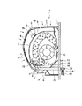
本実施の形態に係る空気調和機の室内機1は、図1ないし3に示すように室内と室外とを仕切る壁2の内側面に取付けられる室内機本体3を有し、室内機本体3の前面部と上面部とには複数の吸込口4が形成されている。室内機本体3の下部には、ルーバー5により開度を調整可能な吹出口6が形成されている。
The
室内機本体3内には、エアフィルタ7と、フィルタ清掃装置8と、熱交換器9と、空調用ファンである横流ファン10と、吸排気ファン11と、吸着体12と、ドレンパン13と、制御器14とが設置されている。また、室内機本体3と室外との間には、共通ダクト15と排気ダクト16と2本の冷媒管17、18とが壁2を貫通して配管されている。なお、図2は各部品における空気の流れを理解するために模式的に表わしたもので、実際の各部品の室内機本体3内の配置とは若干異なっている。
In the
エアフィルタ7は、室内機本体3の前面部と上面部との吸込口4に対向する位置に配置され、メッシュ状に形成されている。吸込口4から吸い込まれる空気中に埃が含まれている場合、この空気がエアフィルタ7を通過する過程で埃がエアフィルタ7により捕捉される。
The
フィルタ清掃装置8は、ブラシ8aと収容ボックス8bとを有し、エアフィルタ7と室内機本体3との間に配置され、エアフィルタ7の表面に沿って移動可能に設けられている。フィルタ清掃装置8がエアフィルタ7の表面に沿って移動する場合に、ブラシ8aが回転駆動されてエアフィルタ7に付着した埃を除去し、除去された埃が収容ボックス8b内に収容される。なお、フィルタ清掃装置8による清掃時には、フィルタ清掃装置8を移動させるモータ(図示せず)と、ブラシ8aを回転駆動させるモータ(図示せず)とが駆動される。そして、収容ボックス8b内に収容された埃は、給排気ファン11により屋外に排出される。なお、フィルタ清掃装置は、給排気ファン11を用いてフィルタ表面を吸い込み口が移動しながらフィルタ表面の塵埃を吸引し、同時に屋外に排気する方式でも良い。
The
熱交換器9は、室外に設置されている室外機(図示せず)内に設けられている室外熱交換器との間に2本の冷媒管17、18によって接続され、内部に冷媒が流れ、冷房運転状態と暖房運転状態とに切替可能に設けられている。熱交換器9は、冷房運転時には低温となって熱交換器9の周囲を流れる空気を冷却し、暖房運転時には高温となって熱交換器9の周囲を流れる空気を加熱する。
The heat exchanger 9 is connected to the outdoor heat exchanger provided in an outdoor unit (not shown) installed outside by two
横流ファン10は、長尺円筒形状に形成された貫流送風機であり、室内機本体3内の長手方向に沿って吸着体12の長手方向と平行に設置される。すなわち、室内機1が壁2に取付けられた場合、室内機本体3内に設置された横流ファン10は、横流ファン10の長手方向が壁2と平行であって水平な方向に向けられている。横流ファン10には、この横流ファン10を回転駆動させるモータ19が連結されている。横流ファン10が駆動されることにより、室内の空気が吸込口4から室内機本体3内に吸い込まれ、吸い込まれた空気が熱交換器9の周囲を通過することにより冷却されて冷風となり又は加熱されて温風となり、冷風又は温風が吹出口6から室内に吹き出す。
The
吸排気ファン11には、この吸排気ファン11を回転駆動させるモータ20が連結されている。吸排気ファン11が回転駆動されることにより、室外の空気が室内機本体3内に吸気され、及び、室外から吸気された空気又は室内の空気が室外に排気される。室外からの空気の吸気は、室内機本体3と室外との間に壁2を貫通して配管された共通ダクト15を用いて行われる。室外への空気の排気は、室内機本体3と室外との間に壁2を貫通して配管された排気ダクト16を介して行われる。共通ダクト15は、ドレンパン13から室外へのドレン水を排水するドレン配管、及び、吸着体12に供給する空気を室外から吸気する吸気ダクトとしての2つの機能を有する。
The intake /
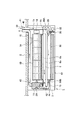
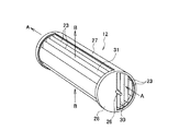
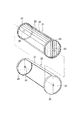
吸着体12は、空気中の水分を吸着し、その後、高温にすることで吸着した水分を空気中に脱離する機能を有する。この吸着体12は、図7及び図8に示すように、吸着板ユニット21と保持体22とにより構成されている。
The
吸着板ユニット21は、長方形の板状に形成されて水分を吸着可能及び脱離可能な複数枚の吸着板23を有し、これらの吸着板23が面と面とを対向させてそれらの面と面との間に通風可能な隙間をもって連結されている。吸着板23は、紙などを素材とする基板と、基板の表面に塗布されたゼオライト等の吸着材粒子とにより形成されている。吸着材は、低温(室温)で水分を吸着し、高温になると吸着した水分を脱離する。
The
複数枚の吸着板23の連結は、吸着板23の長手方向の両端をリング状枠24で固定することにより行われ、吸着板ユニット21の外形形状は円柱状とされている。
The plurality of
リング状枠24には、吸着板23と平行に配置された仕切板25が固定されている。仕切板25は、両端を一対のリング状枠24の直径部分に固定して配置され、吸着板23を2つのグループに2分割すると共に、吸着板ユニット21の補強を兼ねている。仕切板25の長手方向の側面中央部には、仕切板25の長手方向に沿って外側向きに延びた回転軸26が固定されている。
A partition plate 25 arranged in parallel with the
保持体22は、吸着板ユニット21を回転軸26の中心線回りに回転可能に保持している。保持体22は、保持する吸着板ユニット21における一部の吸着板23の長手方向に沿った方向の外周部を気密に覆う第1カバー部27と、保持する吸着板ユニット21における他の一部の吸着板23の長手方向の両端部を気密に覆う一対の第2カバー部28とを有している。第1カバー部27は、吸着板ユニット21の周方向の約180°の範囲を覆う半円筒形に形成されている。第2カバー部28は、半円状に形成されている。第2カバー部28には、回転軸26を回転可能に軸支する支持穴29が形成されている。
The holding
吸着体12には、空気が通風可能な第1空気通路30と第2空気通路31とが形成されている。第1空気通路30は、第1カバー部27と一部の吸着板23とに囲まれて形成され、各吸着板23の間を長手方向(図7に示す矢印A方向)に空気が通風可能とされている。第2空気通路31は、一対の第2カバー部28と他の一部の吸着板23とに囲まれて形成され、各吸着板23の間を吸着板23の長手方向と直交する方向(図7及び図1に示す矢印B方向)に空気が通風可能とされている。なお、第1空気通路30と第2空気通路31との間に仕切板25が位置するようにして、空気が第1空気通路30と第2空気通路31との間を行き来することがないようにしている。
The adsorbent 12 is formed with a
図1及び図2に示すように、吸着体12が室内機本体3内に設置された場合、保持体22が図示しない保持機構により位置固定に保持され、回転軸26には吸着板ユニット21を回転軸26の中心線回りに回転駆動させるモータ32が減速機構33を介して連結されている。減速機構33は、複数のギアを噛み合わせることにより構成されている。
As shown in FIGS. 1 and 2, when the
ドレンパン13は、冷房運転時において熱交換器9で発生するドレン水を受ける皿状の部材であり、横流ファン10の中心線方向に沿った長尺形状に形成され、熱交換器9の下側に配置されている。
The
共通ダクト15は、上述したように、壁2を貫通して室内機本体3内と室外との間に配管され、ドレンパン13から室外へのドレン水の排水と、吸着体12に供給する空気の室外からの吸気とが行われる。
As described above, the
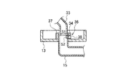
室内機本体3内に位置する共通ダクト15の一端は、ドレンパン13の長手方向の一端側に連結されている。この連結は、図6に示すように、共通ダクト15がドレンパン13の底面を貫通してドレンパン13に固定、保持されることにより行われている。
One end of the
ドレンパン13の底面を貫通した共通ダクト15の先端側は、ドレンパン13の底面より上方に突出している。ドレンパン13の底面より上方に突出した共通ダクト15の先端側には、ドレンパン13内のドレン水を共通ダクト15内に導く第1通路34が形成されている。さらに、共通ダクト15の先端側には、室外から吸気される空気を吸着体12の第1空気通路30に導く第2通路35が接続されている。第2通路35は吸着体12に向けて延出され、その先端部が吸着体12の第1空気通路30の一端側の入口30Aに接続されている。
The front end side of the
第1通路34の流路面積“S1”と第2通路35の流路面積“S2”とを比較すると、第2通路35の流路面積“S2”が第1通路34の流路面積“S1”より大きく設定されている。
Comparing the flow area “S1” of the
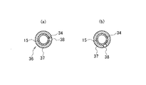
共通ダクト15の先端側には、第1通路34を開閉する開閉機構36が設けられている。この開閉機構36は、共通ダクト15の先端側の外周部に回動可能に嵌合されたリング体37と、このリング体37を回動させるモータ(図示せず)とにより構成されている。リング体37には穴38が形成され、図4及び図5(a)に示すように、穴38と第1通路34とが連通する位置にリング体37を回動させることにより、第1通路34が開放される。また、図5(b)に示すように、穴38と第1通路34とが連通しない位置にリング体37を回動させることにより、第1通路34が閉止される。
An opening /
共通ダクト15の室外に位置する部分には、室外の空気が吸気される吸気部39とドレン水が流れるドレン部40とに分岐される分岐部41が形成されている。吸気部39は、分岐部41における上部側に位置して形成されている。
A
ドレンパン13の長手方向の他端には、排気ダクト16が固定、保持されている。この保持は、図6に示すように、排気ダクト16がドレンパン13の底面に設けられた円筒形の立上げ部60に囲まれる貫通孔61を貫通することにより行われている。
An
排気ダクト16の室内機本体3内に位置する端部は、吸着体12の第1空気通路30の出口30Bに接続されている。さらに、排気ダクト16には、フィルタ清掃装置8の収容ボックス8bに連通する清掃用ダクト42が接続されている。清掃用ダクト42内には、この清掃用ダクト42を開閉するダンパ43が設けられている。排気ダクト16内における出口30Bと清掃用ダクト42の接続部との間には、排気ダクト16を開閉するダンパ44が設けられている。これらのダンパ43、44が、切換手段を構成し、図示しないモータやソレノイド等のアクチュエータにより開閉される。加湿運転は、空気調和機の運転中に実行され、フィルタ清掃は、空気調和機の停止後に実行されるため、ダンパ43、44が同時に開となることはない。
An end portion of the
制御器14は、室内機本体3内の制御対象物の制御を行う。制御器14には、図9に示すように、吸着体12の吸着板ユニット21を回転駆動させるモータ32と、吸排気ファン11を回転駆動させるモータ18と、横流ファン10を回転駆動させるモータ19と、ルーバー5を駆動させるモータ45と、ダンパ43、44を駆動するモータ等のアクチュエータ48,49等と、温度センサ等の各種のセンサと、空気調和機の運転状態を操作するリモコン46からの赤外線信号を受光する受光部47が接続されている。リモコン46には、使用者が操作する各種ボタン(冷房、暖房、加湿、運転/停止、設定温度、風量等)が配置され、それぞれのボタン操作がなされた場合、それぞれの操作内容に応じた赤外線信号が出力されるようになっている。
The
制御器14により行われる制御の概要を図10のフローチャートに基づいて説明する。この制御中には、ドレン水の排水が行われている場合に、共通ダクト15からの吸気、すなわち加湿運転を禁止する制御が含まれている。加湿運転は暖房時に実施されるもので、使用者が、冷房運転と加湿運転を同時に要求する可能性はないが、誤操作等で要求される可能性があるため、冷房運転を優先するようになっている。
An outline of the control performed by the
制御器14は、リモコン46からの信号の入力の有無を監視している(S1)。リモコン46からの信号の入力が有った場合は(S1のYES)、その信号が加湿開始の信号であるか否かが判断される(S2)。
The
ステップS2において、加湿開始の信号ではないと判断された場合には(S2のNO)、停止信号か否かが判別される(S3)。ステップS2において、加湿開始の信号ではないと判断される信号としては、停止信号、暖房運転の開始信号、冷房運転の開始信号、設定温度の変更信号等が挙げられる。 If it is determined in step S2 that the signal is not a humidification start signal (NO in S2), it is determined whether or not it is a stop signal (S3). Examples of the signal that is determined not to be a humidification start signal in step S2 include a stop signal, a heating operation start signal, a cooling operation start signal, and a set temperature change signal.
ステップS2において、加湿開始の信号であると判断された場合には(S2のYES)、空気調和機の現在の運転状態が冷房運転であるか否かが判断される(S4)。冷房運転時には熱交換器9においてドレン水が発生し、共通ダクト15を通してドレン水の排水が行われていることを意味する。
If it is determined in step S2 that the signal is a humidification start signal (YES in S2), it is determined whether or not the current operating state of the air conditioner is a cooling operation (S4). It means that drain water is generated in the heat exchanger 9 during cooling operation, and drain water is drained through the
ステップS4において、現在の運転状態が冷房運転ではないと判断された場合には(S4のNO)、吸排気ファン11が駆動され、室外の空気を共通ダクト15を通して吸気することにより加湿運転が開始される(S5)。
If it is determined in step S4 that the current operation state is not the cooling operation (NO in S4), the intake /
一方、ステップS4において、現在の運転状態が冷房運転であると判断された場合には(S4のYES)、加湿開始の信号がキャンセルされ(S6)、ここに、ドレン水の排水が行われている場合に、共通ダクト15からの吸気を禁止する手段が実行される。すなわち、冷房運転が加湿運転に優先される。
On the other hand, if it is determined in step S4 that the current operating state is the cooling operation (YES in S4), the humidification start signal is canceled (S6), and drain water is drained here. If it is, the means for prohibiting intake from the
このような構成において、冷房運転時には開閉機構36により第1通路34が開放される。即ち、リング体37が所定の位置に回動され、図4及び図5(a)に示すように、リング体37に形成された穴38と第1通路34とが連通される。
In such a configuration, the
このため、冷房運転時において熱交換器9で発生したドレン水がドレンパン13上に流れ落ちると、このドレン水は穴38と第1通路34とを通って共通ダクト15内に流入し、共通ダクト15内とドレン部40内とを流れて室外に排水される。
For this reason, when drain water generated in the heat exchanger 9 flows down on the
加湿運転時には、図10のフローチャートに示すステップS5で、開閉機構36により第1通路34が閉止され、吸排気ファン11が駆動される。なお、この加湿運転時には、清掃用ダクト42内のダンパ43が閉止され、排気ダクト16内のダンパ44が開放されている。開閉機構36による第1通路34の閉止は、リング体37が図5(b)に示す位置に回動し、リング体37の穴38と第1通路34との連通が遮断されることにより行われる。
During the humidifying operation, the
開閉機構36により第1通路34が閉止され、ダンパ43が閉止されるとともにダンパ44が開放された状態で吸排気ファン11が駆動されると、室外の空気が吸気部39から吸気され、共通ダクト15内と第2通路35内とを通って吸着体12側へ流れる。共通ダクト15内と第2通路35内とを流れる空気は、入口30Aから吸着体12の第1空気通路30内に流入する。室外から吸気された空気が吸着体12の第1空気通路30内を流れる過程において、空気中の水分が第1空気通路30内に位置する吸着板23に吸着される。
When the intake /
第1空気通路30内を通過した空気は、水分が吸着板23に吸着されることにより湿度が低下し、湿度が低下した空気は排気ダクト16内を通って室外に排気される。
The air that has passed through the
加湿運転時には、予め設定された時間毎にモータ32が駆動され、吸着板ユニット21が回転軸26の回りに約180°ずつ回転する。この回転により、回転前に第1空気通路30内に位置して水分の吸着が行われた吸着板23が第2空気通路31内に移動し、及び、回転前に第2空気通路31内に位置していた吸着板23が第1空気通路30内に移動する。加湿運転が行われるのは暖房運転が行われる冬場であり、第2空気通路31には熱交換器9により加熱された温風の一部が図1の矢印Bで示す方向に流れている。これにより、第2空気通路31内に位置する吸着板23が加熱されてこの吸着板23から水分が脱離され、脱離された水分は横流ファン10により熱交換器9側へ吸い込まれた後に吹出口6から室内に吹出し、室内が加湿される。
During the humidifying operation, the
一方、図10のフローチャートに示すステップS3において、受信した信号が停止信号であると判断された場合(S3のYES)、空調運転が停止される(S7)。続いて、フィルタ清掃が必要か否かが判別される(S11)。清掃が必要か否かの判断は、例えば、空気調和機の積算運転時間が所定時間(例えば50時間)を超えたか否かのような判別法が一般的である。ここで、フィルタ清掃が必要と判断されれば、フィルタ清掃装置8を駆動させてフィルタ表面の塵埃が取り除かれる(S9)。そして、塵埃の屋外への排気運転が実行される(S10)。ここでは、清掃用ダクト42内のダンパ43を開放し、排気ダクト16内のダンパ44を閉止し、吸排気ファン11が駆動される。これにより、エアフィルタ7から除去され、収納ボックス8bに収容された埃が清掃用ダクト42内と排気ダクト16内とを流れ、室外に放出される。なお、収納ボックス8bの清掃用ダクト42の接続側と反対側には、小さな開口8cが設けられており、吸排気ファン11の運転によって、この開口8cから吸引された室内機内の空気が収納ボックス8b、清掃用ダクト42、吸排気ファン11を経由して排気ダクト16から屋外に排気される。したがって、塵埃の排気運転においては、共通ダクト15は用いられず、塵埃が共通ダクト15に流れ出ることはない。その後、所定時間が経過して清掃が終了したか否かが判断され(S11)、塵埃排気運転を含めた清掃運転が完了すれば(S11のYES)、吸排気ファン11を停止し(S12)、運転を終了する。
On the other hand, when it is determined in step S3 shown in the flowchart of FIG. 10 that the received signal is a stop signal (YES in S3), the air conditioning operation is stopped (S7). Subsequently, it is determined whether or not filter cleaning is necessary (S11). The determination of whether or not cleaning is necessary is generally a determination method such as whether or not the accumulated operation time of the air conditioner has exceeded a predetermined time (for example, 50 hours). If it is determined that the filter needs to be cleaned, the
なお、ステップS3にて停止信号でないと判断された場合は(S3のNO)、その入力信号に応じた制御が実行される(S13)。また、ステップS8で、清掃不要と判断された場合は(S8のNO)、そのまま終了する。 If it is determined in step S3 that the signal is not a stop signal (NO in S3), control according to the input signal is executed (S13). If it is determined in step S8 that cleaning is not necessary (NO in S8), the process ends.
この室内機1では、ドレン水の室外への排水と、室外からの加湿用の空気の吸気とを1本の共通ダクト15を用いて行うため、これらの共通ダクト15や排気ダクト16を配管するために壁2にあける穴の数を少なくすることができるとともに、あける穴の大きさを小さくすることができる。
In this
しかも、この共通ダクト15は、夏場等における冷房運転時のドレン水の排水と、冬場等の加湿用の空気の室外からの吸気とに用いられる。このため、ドレン水の排水中や、ドレン水の排水直後に室外からの空気の吸気が行われることがなく、空気中に含まれる埃がドレン水中に入り込んだり、或いは、吸気される空気中の埃が濡れた共通ダクト15の内面に付着することがなく、共通ダクト15内に埃が付着して共通ダクト15が詰まるという事態の発生を防止することができる。
In addition, the
また、室外からの空気の吸気時には、共通ダクト15内にドレン水が存在しないため、吸気する空気の通路抵抗を小さくすることができ、空気の吸気効率を高めることができる。
Further, when air is taken in from the outside, since there is no drain water in the
さらに、室外からの空気の吸気時には、共通ダクト15内にドレン水が存在しないめ、吸気される空気によるドレン水の逆流という事態の発生を防止することができる。
Furthermore, since there is no drain water in the
しかも、室内機1には、ドレン水の排水が行われている場合に、共通ダクト15からの吸気を禁止する手段が設けられているため、ドレン水の排水が行われている場合に共通ダクト15からの吸気を確実に防止することができる。
Moreover, since the
すなわち、排気ダクト16を加湿用空気の屋外排気とフィルタ清掃装置8からの塵埃の屋外排出と兼用し、共通ダクト15を加湿用空気の吸引とドレン水の配水管と兼用し、さらに給排気ファン11を加湿と塵埃の屋外排出に兼用することで、加湿とフィルタ清掃の両方を簡単な構成で、効率よく、かつダクトの目詰まり等を起こすことのない室内機1を得ることができる。
That is, the
また、共通ダクト15をドレン水の排水と加湿用の空気の吸気とに用いる場合の切替えを、第1通路34を開閉する開閉機構36により確実に行うことができる。
In addition, switching when the
ドレンパン13への共通ダクト15の連結部位の先端側に、ドレン水を共通ダクト15に導く第1通路34と、室外から吸気される空気を吸着体12に導く第2通路35とが設けられているため、加湿運転時に、第1通路34を開放させることにより、室外から吸気される空気に加えて、第1通路34から吸気される室内の空気を吸着体12側に供給することができる。このため、室外の空気の湿度が低い場合には、必要に応じて室内の空気の水分を用いて室内の加湿を行い、室外の空気の湿度が低い場合であっても加湿性能を維持することができる。
A
第1通路34の流路面積“S1”と第2通路35の流路面積“S2”とを比較すると、第2通路35の流路面積“S2”が第1通路34の流路面積“S1”より大きく設定されている。このため、図5(b)に示すように第1通路34を閉止して室外の空気を吸気する場合、第1通路34の隙間部分からの空気の入り込みを抑えることができ、室外からの空気の吸気性能を高めることができる。
Comparing the flow area “S1” of the
共通ダクト15の室外に位置する部分には、吸気部39とドレン部40とに分岐される分岐部41が形成され、吸気部39は分岐部41における上部側に位置しているため、ドレン水の排水時に吸気部39からのドレン水の漏れ出しを防止することができ、ドレン水をドレン部40内を通して目的とする排水箇所へ排水することができる。
A
排気ダクト16と吸気ダクトの機能を備えた共通ダクト15と室内機本体3内での配管処理に関し、ドレンパン13の一端側に共通ダクト15を保持し、ドレンパン13の他端側に排気ダクト16を固定、保持している。このようにして、ドレンパン13を共通ダクト15と排気ダクト16とを保持する保持部材として用いるため、室内機本体3内におけるダクトの配管処理を手間をかけず容易に行うことができる。
With respect to the
3…室内機本体、4…吸込口、6…吹出口、7…フィルタ、8…フィルタ清掃装置、9…熱交換器、10…空調用ファン、11…吸排気ファン、12…吸着体、13…ドレンパン、15…共通ダクト(吸気ダクト)、16…排気ダクト、34…第1通路、35…第2通路、36…開閉機構、39…吸気部、40…ドレン部、41…分岐部、43、44…切替手段
DESCRIPTION OF
Claims (7)
前記室内機本体内に設置され、前記吸込口から吸い込まれて前記吹出口から吹き出す空気の流れを発生させる空調用ファンと、
前記室内機本体内に設置され、前記吸込口から吸い込まれて前記吹出口から吹き出す空気を冷却又は加熱する熱交換器と、
前記熱交換器で発生するドレン水を受けるドレンパンと、
前記吸込口と熱交換器との間に設けられ、前記吸込口から吸い込まれた室内空気中の塵埃を捕捉するフィルタと、
このフィルタに付着した塵埃を取るフィルタ清掃装置と、
前記室内機本体内に設置され、空気中の水分の吸着と吸着した水分の脱離とが行われる吸着体と、
前記室内機本体内と室外との間に配管された排気ダクトと、
吸い込み側から吸い込んだ空気を、前記排気ダクトを介して室外に排気する吸排気ファンと、
前記室内機本体内と室外との間に配管され、前記ドレンパンから室外へのドレン水の排水と、前記吸着体に供給する空気の吸気とが行われる共通ダクトと、
前記吸排気ファンの吸い込み側を前記フィルタ清掃装置に接続して塵埃を含む空気を吸気するか、前記吸着体を介して共通ダクトに接続し、前記吸着体で水分が吸着された後の空気を吸気するかを切換え可能な切換手段と、
を備えることを特徴とする空気調和機の室内機。 An indoor unit body that is formed with an air inlet into which indoor air is sucked and an air outlet through which air sucked from the air inlet is blown into the room;
An air conditioning fan that is installed in the indoor unit main body and generates a flow of air that is sucked from the suction port and blown out from the outlet;
A heat exchanger that is installed in the indoor unit main body, cools or heats the air sucked from the suction port and blown out from the blowout port;
A drain pan for receiving drain water generated in the heat exchanger;
A filter that is provided between the suction port and the heat exchanger and captures dust in indoor air sucked from the suction port;
A filter cleaning device for removing dust adhering to the filter;
An adsorbent that is installed in the indoor unit main body and performs adsorption of moisture in the air and desorption of adsorbed moisture;
An exhaust duct piped between the interior of the indoor unit body and the outside;
An intake / exhaust fan that exhausts air sucked from the suction side to the outside through the exhaust duct;
A common duct that is piped between the interior of the indoor unit main body and the outside, and that drains drain water from the drain pan to the outside and sucks air supplied to the adsorbent, and
The suction side of the intake / exhaust fan is connected to the filter cleaning device to suck in air containing dust, or connected to a common duct via the adsorbent, and the air after moisture is adsorbed by the adsorbent Switching means capable of switching whether to inhale, and
An air conditioner indoor unit comprising:
前記室内機本体内に設置され、前記吸込口から吸い込まれて前記吹出口から吹き出す空気の流れを発生させる空調用ファンと、
前記室内機本体内に設置され、前記吸込口から吸い込まれて前記吹出口から吹き出す空気を冷却又は加熱する熱交換器と、
前記熱交換器で発生するドレン水を受けるドレンパンと、
前記室内機本体内に設置され、空気中の水分の吸着と吸着した水分の脱離とが行われる吸着体と、
室外から前記吸着体に向けて空気を吸気す吸気ダクトと、
前記吸着体を通過した後の空気を室外に排気する排気ダクトと、
を備え、
前記吸気ダクトおよび前記排気ダクトがともに前記ドレンパンに固定されていることを特徴とする空気調和機の室内機。 An indoor unit body that is formed with an air inlet into which indoor air is sucked and an air outlet through which air sucked from the air inlet is blown into the room;
An air conditioning fan that is installed in the indoor unit main body and generates a flow of air that is sucked from the suction port and blown out from the outlet;
A heat exchanger that is installed in the indoor unit main body, cools or heats the air sucked from the suction port and blown out from the blowout port;
A drain pan for receiving drain water generated in the heat exchanger;
An adsorbent that is installed in the indoor unit main body and performs adsorption of moisture in the air and desorption of adsorbed moisture;
An intake duct for sucking air from outside to the adsorbent,
An exhaust duct for exhausting the air after passing through the adsorbent to the outside;
With
An indoor unit of an air conditioner, wherein both the intake duct and the exhaust duct are fixed to the drain pan.
Priority Applications (1)
| Application Number | Priority Date | Filing Date | Title |
|---|---|---|---|
| JP2006336259A JP2008145090A (en) | 2006-12-13 | 2006-12-13 | Indoor unit of air conditioner |
Applications Claiming Priority (1)
| Application Number | Priority Date | Filing Date | Title |
|---|---|---|---|
| JP2006336259A JP2008145090A (en) | 2006-12-13 | 2006-12-13 | Indoor unit of air conditioner |
Publications (1)
| Publication Number | Publication Date |
|---|---|
| JP2008145090A true JP2008145090A (en) | 2008-06-26 |
Family
ID=39605462
Family Applications (1)
| Application Number | Title | Priority Date | Filing Date |
|---|---|---|---|
| JP2006336259A Pending JP2008145090A (en) | 2006-12-13 | 2006-12-13 | Indoor unit of air conditioner |
Country Status (1)
| Country | Link |
|---|---|
| JP (1) | JP2008145090A (en) |
Cited By (9)
| Publication number | Priority date | Publication date | Assignee | Title |
|---|---|---|---|---|
| JP2010065896A (en) * | 2008-09-09 | 2010-03-25 | Daikin Ind Ltd | Indoor unit of air conditioning device |
| CN107218704A (en) * | 2017-06-19 | 2017-09-29 | 广东美的制冷设备有限公司 | Control method, control system and the air conditioner of air conditioner |
| CN110486804A (en) * | 2019-08-14 | 2019-11-22 | 青岛海尔空调器有限总公司 | Refrigerating humidifying device and air-conditioning |
| CN111998507A (en) * | 2020-09-02 | 2020-11-27 | 海信(山东)空调有限公司 | Air conditioner control method and air conditioner |
| CN112161333A (en) * | 2020-10-13 | 2021-01-01 | 珠海格力电器股份有限公司 | Humidification structure, air conditioner indoor unit, air conditioner and control method of air conditioner |
| JP2021195914A (en) * | 2020-06-15 | 2021-12-27 | 日立ジョンソンコントロールズ空調株式会社 | Air-conditioner |
| JP7141003B1 (en) | 2021-08-06 | 2022-09-22 | ダイキン工業株式会社 | air conditioning indoor unit |
| JP7148690B1 (en) | 2021-08-31 | 2022-10-05 | ダイキン工業株式会社 | air conditioner |
| CN115355565A (en) * | 2022-04-22 | 2022-11-18 | 青岛海尔空调器有限总公司 | Air treatment device |
Citations (5)
| Publication number | Priority date | Publication date | Assignee | Title |
|---|---|---|---|---|
| JPS56105719A (en) * | 1980-01-25 | 1981-08-22 | Biru Daiko:Kk | Electromagnetic filter for atomic energy |
| JP2002081701A (en) * | 2000-08-31 | 2002-03-22 | Toshiba Kyaria Kk | Humidifying unit |
| JP2004317061A (en) * | 2003-04-17 | 2004-11-11 | Sharp Corp | Gas-liquid separator and air conditioner having the same |
| JP2005140379A (en) * | 2003-11-06 | 2005-06-02 | Mitsubishi Electric Corp | Intake device of air conditioner, and air conditioner |
| JP2006183996A (en) * | 2003-09-12 | 2006-07-13 | Matsushita Electric Ind Co Ltd | Air conditioner |
-
2006
- 2006-12-13 JP JP2006336259A patent/JP2008145090A/en active Pending
Patent Citations (5)
| Publication number | Priority date | Publication date | Assignee | Title |
|---|---|---|---|---|
| JPS56105719A (en) * | 1980-01-25 | 1981-08-22 | Biru Daiko:Kk | Electromagnetic filter for atomic energy |
| JP2002081701A (en) * | 2000-08-31 | 2002-03-22 | Toshiba Kyaria Kk | Humidifying unit |
| JP2004317061A (en) * | 2003-04-17 | 2004-11-11 | Sharp Corp | Gas-liquid separator and air conditioner having the same |
| JP2006183996A (en) * | 2003-09-12 | 2006-07-13 | Matsushita Electric Ind Co Ltd | Air conditioner |
| JP2005140379A (en) * | 2003-11-06 | 2005-06-02 | Mitsubishi Electric Corp | Intake device of air conditioner, and air conditioner |
Cited By (15)
| Publication number | Priority date | Publication date | Assignee | Title |
|---|---|---|---|---|
| JP2010065896A (en) * | 2008-09-09 | 2010-03-25 | Daikin Ind Ltd | Indoor unit of air conditioning device |
| CN107218704A (en) * | 2017-06-19 | 2017-09-29 | 广东美的制冷设备有限公司 | Control method, control system and the air conditioner of air conditioner |
| CN110486804A (en) * | 2019-08-14 | 2019-11-22 | 青岛海尔空调器有限总公司 | Refrigerating humidifying device and air-conditioning |
| JP2021195914A (en) * | 2020-06-15 | 2021-12-27 | 日立ジョンソンコントロールズ空調株式会社 | Air-conditioner |
| JP7402754B2 (en) | 2020-06-15 | 2023-12-21 | 日立ジョンソンコントロールズ空調株式会社 | air conditioner |
| CN111998507A (en) * | 2020-09-02 | 2020-11-27 | 海信(山东)空调有限公司 | Air conditioner control method and air conditioner |
| CN111998507B (en) * | 2020-09-02 | 2021-12-03 | 海信(山东)空调有限公司 | Air conditioner control method and air conditioner |
| CN112161333A (en) * | 2020-10-13 | 2021-01-01 | 珠海格力电器股份有限公司 | Humidification structure, air conditioner indoor unit, air conditioner and control method of air conditioner |
| CN112161333B (en) * | 2020-10-13 | 2024-03-29 | 珠海格力电器股份有限公司 | Humidification structure, air conditioner indoor unit, air conditioner and control method of air conditioner |
| JP7141003B1 (en) | 2021-08-06 | 2022-09-22 | ダイキン工業株式会社 | air conditioning indoor unit |
| JP2023023961A (en) * | 2021-08-06 | 2023-02-16 | ダイキン工業株式会社 | Air-conditioning indoor unit |
| JP7148690B1 (en) | 2021-08-31 | 2022-10-05 | ダイキン工業株式会社 | air conditioner |
| WO2023032738A1 (en) * | 2021-08-31 | 2023-03-09 | ダイキン工業株式会社 | Air-conditioning device |
| JP2023034985A (en) * | 2021-08-31 | 2023-03-13 | ダイキン工業株式会社 | Air-conditioning device |
| CN115355565A (en) * | 2022-04-22 | 2022-11-18 | 青岛海尔空调器有限总公司 | Air treatment device |
Similar Documents
| Publication | Publication Date | Title |
|---|---|---|
| JP2008145090A (en) | Indoor unit of air conditioner | |
| KR100708358B1 (en) | Blowing device and air conditioner using the same | |
| JP4240115B2 (en) | Air conditioner | |
| US20090044555A1 (en) | Desiccant dehumidifier | |
| JP2007139410A (en) | Ventilation system | |
| WO2017043104A1 (en) | Dehumidification and humidification device | |
| JP3608548B2 (en) | Ventilator and air conditioner | |
| JP3559421B2 (en) | Humidifier | |
| JPH08270980A (en) | Air conditioner with dehumidifying and humidifying functions | |
| US20220074608A1 (en) | Humidity control unit and humidity control system | |
| JP2003314858A (en) | Air conditioner | |
| KR101817092B1 (en) | Air cleaner | |
| KR20080092201A (en) | Ventilation unit and air conditioner having the same | |
| JP5007098B2 (en) | Adsorber, humidity control device and air conditioner indoor unit | |
| JP2005024233A (en) | Humidity controller | |
| JP2009092299A (en) | Humidity conditioner | |
| JP4714132B2 (en) | Air conditioner | |
| JP2002253656A (en) | Air cleaner | |
| JP2001190925A (en) | Dehumidifying/drying apparatus and dehumidifying/drying method | |
| JP2000314548A (en) | Positive pressure air supply air cleaner | |
| JP2009024917A (en) | Adsorbent device, humidity adjusting device, and indoor machine of air conditioner | |
| KR100352430B1 (en) | air-wnditional system and air-wnditional control methode having both indoors dehumidificalion system and indoors humidificatian system | |
| JP2008281238A (en) | Supply and exhaust device | |
| JP2018100784A (en) | Air conditioner | |
| WO2023032397A1 (en) | Air conditioner |
Legal Events
| Date | Code | Title | Description |
|---|---|---|---|
| A711 | Notification of change in applicant |
Free format text: JAPANESE INTERMEDIATE CODE: A712 Effective date: 20080528 |
|
| A621 | Written request for application examination |
Free format text: JAPANESE INTERMEDIATE CODE: A621 Effective date: 20090918 |
|
| A977 | Report on retrieval |
Free format text: JAPANESE INTERMEDIATE CODE: A971007 Effective date: 20110617 |
|
| A131 | Notification of reasons for refusal |
Free format text: JAPANESE INTERMEDIATE CODE: A131 Effective date: 20110628 |
|
| A02 | Decision of refusal |
Free format text: JAPANESE INTERMEDIATE CODE: A02 Effective date: 20111025 |