EP2088083A1 - Strip-pack apparatus - Google Patents
Strip-pack apparatus Download PDFInfo
- Publication number
- EP2088083A1 EP2088083A1 EP07829125A EP07829125A EP2088083A1 EP 2088083 A1 EP2088083 A1 EP 2088083A1 EP 07829125 A EP07829125 A EP 07829125A EP 07829125 A EP07829125 A EP 07829125A EP 2088083 A1 EP2088083 A1 EP 2088083A1
- Authority
- EP
- European Patent Office
- Prior art keywords
- item
- strip pack
- conveying
- attaching
- unit
- Prior art date
- Legal status (The legal status is an assumption and is not a legal conclusion. Google has not performed a legal analysis and makes no representation as to the accuracy of the status listed.)
- Withdrawn
Links
Images




Classifications
-
- B—PERFORMING OPERATIONS; TRANSPORTING
- B65—CONVEYING; PACKING; STORING; HANDLING THIN OR FILAMENTARY MATERIAL
- B65B—MACHINES, APPARATUS OR DEVICES FOR, OR METHODS OF, PACKAGING ARTICLES OR MATERIALS; UNPACKING
- B65B15/00—Attaching articles to cards, sheets, strings, webs, or other carriers
- B65B15/04—Attaching a series of articles, e.g. small electrical components, to a continuous web
-
- Y—GENERAL TAGGING OF NEW TECHNOLOGICAL DEVELOPMENTS; GENERAL TAGGING OF CROSS-SECTIONAL TECHNOLOGIES SPANNING OVER SEVERAL SECTIONS OF THE IPC; TECHNICAL SUBJECTS COVERED BY FORMER USPC CROSS-REFERENCE ART COLLECTIONS [XRACs] AND DIGESTS
- Y10—TECHNICAL SUBJECTS COVERED BY FORMER USPC
- Y10T—TECHNICAL SUBJECTS COVERED BY FORMER US CLASSIFICATION
- Y10T156/00—Adhesive bonding and miscellaneous chemical manufacture
- Y10T156/17—Surface bonding means and/or assemblymeans with work feeding or handling means
-
- Y—GENERAL TAGGING OF NEW TECHNOLOGICAL DEVELOPMENTS; GENERAL TAGGING OF CROSS-SECTIONAL TECHNOLOGIES SPANNING OVER SEVERAL SECTIONS OF THE IPC; TECHNICAL SUBJECTS COVERED BY FORMER USPC CROSS-REFERENCE ART COLLECTIONS [XRACs] AND DIGESTS
- Y10—TECHNICAL SUBJECTS COVERED BY FORMER USPC
- Y10T—TECHNICAL SUBJECTS COVERED BY FORMER US CLASSIFICATION
- Y10T156/00—Adhesive bonding and miscellaneous chemical manufacture
- Y10T156/17—Surface bonding means and/or assemblymeans with work feeding or handling means
- Y10T156/1702—For plural parts or plural areas of single part
- Y10T156/1712—Indefinite or running length work
- Y10T156/1734—Means bringing articles into association with web
-
- Y—GENERAL TAGGING OF NEW TECHNOLOGICAL DEVELOPMENTS; GENERAL TAGGING OF CROSS-SECTIONAL TECHNOLOGIES SPANNING OVER SEVERAL SECTIONS OF THE IPC; TECHNICAL SUBJECTS COVERED BY FORMER USPC CROSS-REFERENCE ART COLLECTIONS [XRACs] AND DIGESTS
- Y10—TECHNICAL SUBJECTS COVERED BY FORMER USPC
- Y10T—TECHNICAL SUBJECTS COVERED BY FORMER US CLASSIFICATION
- Y10T156/00—Adhesive bonding and miscellaneous chemical manufacture
- Y10T156/17—Surface bonding means and/or assemblymeans with work feeding or handling means
- Y10T156/1702—For plural parts or plural areas of single part
- Y10T156/1744—Means bringing discrete articles into assembled relationship
Definitions
- the present invention is in the technical field of manufacturing a product called strip pack, in which a plurality of items is adhered to a backing sheet and displayed in a state of being suspended.
- strip pack meaning a packaging configuration in which an item can be taken by pulling it off
- a strip pack apparatus for manufacturing this kind of strip pack includes, for example, the apparatus described in Patent Document 1, which is arranged directly below a vertical bag-making packaging machine, in which after an item manufactured at the packaging machine is moved by a left and right pair of grasping arms grasping the item at the upper two sides thereof to the adhering position below, the item is adhered to the backing sheet at the upper end portion thereof.
- the apparatus described in Patent Document 2 is also arranged directly below a vertical bag-making packaging machine, and after an item manufactured at the packaging machine is grasped and held at the upper single surface thereof by a suction cup and moved to the adhering position in front, the item is adhered to the backing sheet at the upper end portion thereof.
- the basic configuration of this kind of a strip pack apparatus includes a conveying means for conveying an item roughly in the horizontal direction, a moving means for moving the item conveyed by this conveying means to an attaching position, and an attaching means for attaching the item moved by this moving means to a backing sheet.
- the present invention has an object of improving the disposition of the attaching position with respect to the conveying means, in a highly versatile strip pack apparatus configured independently from the devices on the upstream side and downstream side thereof, so that an item does not have to be moved up by the moving means, and the width of the strip pack apparatus does not increase, and also, the mechanisms and operations for moving an item to the attaching position do not become complicated.
- the strip pack apparatus for manufacturing a product with items attached on a backing sheet, according to a first aspect of the present invention for achieving the above described object includes a conveying means for conveying an item roughly in the horizontal direction, a moving means for moving the item conveyed by this conveying means slantingly downward on the front side in the conveying direction from the conveying means, and an attaching means for attaching the item moved by this moving means to a backing sheet.
- the strip pack apparatus is the strip pack apparatus as set forth in the first aspect, wherein the moving means grasps the end portion on the front side in the conveying direction of the item conveyed by the conveying means, and moves the item slantingly downward, and the attaching means attaches the item to a backing sheet at the end portion grasped by the moving means.
- the strip pack apparatus is the strip pack apparatus as set forth in the first or the second aspect, wherein the conveying means conveys the item to a terminal end portion of the conveying means, and the terminal end portion of the conveying means tilts so that the front side in the conveying direction becomes lower when the item is moved by the moving means.
- the strip pack apparatus since the strip pack apparatus does not move the item conveyed by the conveying means directly below from the conveying means, but moves the item slantingly downward on the front side in the conveying direction from the conveying means, in other words, since the attaching position is arranged in a position slanting downward on the front side in the conveying direction with respect to the conveying means, the item does not have to be moved up by the moving means like when the attaching position is arranged above the conveying means, and the width of the strip pack apparatus does not increase like when the attaching position is arranged to the side of the conveying means, and also, the mechanisms and operations for moving the item to the attaching position do not become complicated like when the attaching position is arranged directly below the conveying means.
- the item when the item is moved slantingly downward on the front side in the conveying direction from the conveying means, the item can be moved to the attaching position without having to go through the trouble of removing the conveying means, and as a result, the speed of the strip pack apparatus can be increased.
- the moving means for moving the item to the attaching position is also used as the grasp means for holding the item, the configuration of the strip pack apparatus is simplified.
- the moving means which is the grasp means, holds the end portion of the item to be attached to the backing sheet, and thus, the end portion is kept to be flat. As a result, the end portion overlaps favorably with the backing sheet, and the item is attached to the backing sheet in a favorable state.
- the terminal end portion of the conveying means tilts so that the front side in the conveying direction becomes lower, the item is moved smoothly slantingly downward, and this prevents a big impact from acting on the item when it is being moved.
- Figs. 1 and 2 show a perspective view and a side view respectively, conceptually showing a strip pack apparatus 1 according to an embodiment of the present invention.
- Fig. 4 shows the flow of a series of processes, from a process of guiding a packaged item (bag X) to the interior of the strip pack apparatus 1, to a process of attaching the packaged item to a tape T.
- Figs. 3(a) and 3(b) show the packaged item (bag X) and the strip pack SP, respectively.
- the bag X has a hollow portion Y in which snacks and the like are filled, and two seal portions Z at the top and bottom ( Fig. 3(a) ).
- the top seal portion Z refers to the side of the seal portion Z on which the letters "SNACK" written on the bag can be read from a normal viewpoint, when one of the two seal portions Z is picked and lifted up.
- a predetermined number of bags X are aligned and attached on the tape T ( Fig. 3(b) ).
- the top seal portions Z of the bags X are attached to the tape T.
- a hole punched is provided on a portion near an end of the tape T for allowing the strip pack SP to be displayed suspended.
- the strip pack apparatus 1 having great versatility is an apparatus for manufacturing strip packs SP, and is independent from both the devices on the upstream and downstream sides. Furthermore, a packaging unit and the like for filling articles into the bags X through automatic packaging are included in the device on the upstream side. A device and the like for putting the strip packs SP into a box are included in the device on the downstream side.
- the strip pack apparatus 1 includes a body unit 2, a supply conveyor 3, a lead-in conveyor 4, a drop conveyor 5, a discharge conveyor 6, a brush unit 7, a grasp unit 8, an attaching unit 9, and a tape feeding unit 10.
- the supply conveyor 3, the lead-in conveyor 4, the drop conveyor 5, the discharge conveyor 6, the brush unit 7, the grasp unit 8, the attaching unit 9, and the tape feeding unit 10 are supported by the body unit 2.
- the supply conveyor 3 supplies the bags X produced at the device on the upstream side to the strip pack apparatus 1. More specifically, the supply conveyor 3 is arranged outside the strip pack apparatus 1, and conveys the bags X in the direction roughly horizontal, and in the direction of arrow a ( Fig. 2 ).
- the lead-in conveyor 4 guides the bags X supplied by the supply conveyor 3 to the interior of the strip pack apparatus 1. More specifically, the lead-in conveyor 4 conveys the bags X in a direction roughly horizontal, and in the direction of arrow b ( Fig. 2 ). At this time, the bags X are conveyed in the direction of arrow b with the top seal portions Z to the front.
- the arrow b direction is the opposite direction from the arrow a direction.
- the lead-in conveyor 4 can be comprehended to be the conveying means for conveying bags X roughly in the horizontal direction, in view of the lead-in conveyor 4 conveying bags X roughly in the horizontal direction.
- the arrow b direction can be comprehended as the conveying direction.
- a member 12 is arranged on the starting end portion side of the lead-in conveyor 4 that conveys the bags X in the arrow b direction ( Fig. 2 ).
- the member 12 prevents the bags X, dropped from the supply conveyor 3, from not being entered into the strip pack apparatus 1. Furthermore, the member 12 is omitted in Fig. 1 .
- the drop conveyor 5 is positioned on the terminal end portion side of the lead-in conveyor 4, and guides the bags X conveyed by the lead-in conveyor 4 to the brush unit 7.
- the conveying means described above can include the drop conveyor 5.
- the drop conveyor 5 can be comprehended to be the terminal end portion of the conveying means.
- the drop conveyor 5 can move in the arrow e direction with a fulcrum 51 as the center thereof.
- the drop conveyor 5 tilts with the movement thereof in the arrow e direction.
- the movement of the drop conveyor 5 is linked to the movement of the grasp unit 8. This is described in detail in "Grasp Unit 8".
- the brush unit 7 undoes the wrinkles on the top seal portions Z of the bags X being conveyed thereto by the drop conveyor 5. Details will be described using Fig. 5 .
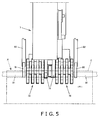
- Fig. 5 is a diagram of the brush unit 7 viewed from above.
- the brush unit 7 is arranged on the distant side of the arrow b with respect to the drop conveyor 5 ( Fig. 4 ), and includes two of each of the brushes 72 and supporting members 71.
- only the upper brush 72 and the supporting member 71 for supporting the upper brush 72 are shown in Fig. 5 .
- the brushes 72 undo wrinkles on the seal portions Z of bags X. More specifically, the brush unit 7 includes two brushes 72 for sandwiching the seal portion Z from the upper side and the lower side. With both the upper and the lower brushes 72, a plurality of thin disk-shaped separated brushes is arranged side by side at predetermined intervals. Spongious brushes, brushes like scrubbing brushes with wire rods tied together radially, and the like, can be adopted for the brushes 72.
- the upper brush 72 rotates from the base portion side to the edge portion side of the seal portion Z, in the state of being in contact with the upper surface of the seal portion Z.
- the lower brush 72 rotates from the base portion side to the edge portion side of the seal portion Z, in the state of being in contact with the under surface of the seal portion Z.
- the upper and lower brushes 72 are supported by the supporting members 71 arranged one at the top and one at the bottom, respectively.
- Fig. 6 shows the grasp unit 8 viewed from the side.
- the configuration and the operation of the grasp unit 8 and the positional relationship thereof with the brush unit 7 will be described below using Figs. 6 and 4 .
- the grasp unit 8 grasps the top seal portions Z of the bags X dewrinkled by the brush unit 7 from the top seal portion Z side (distant side of arrow b) with respect to the bags X. More specifically, the grasp unit 8 is arranged on the distant side of the arrow b with respect to the drop conveyor 5, and includes a pair of grip fingers 81, hands 82, arms 83, and guide rails 84 ( Fig. 4 ).
- the pair of grip fingers 81 is arranged one on the upper side and the other on the lower side, and can grasp the seal portions Z by sandwiching the seal portions Z from above and below.
- This pair of grip fingers 81 each includes a finger body 81a and a grasp portion 81b.
- the finger bodies 81a can move (pivot) in the arrow f direction ( Fig. 6 ), with fulcrums 82a provided on the hand 82 as the centers thereof.
- the grasp portions 81b are mounted on the tip of the finger bodies 81a. Rubber and the like, having elasticity, is adopted for the grasp portions 81 b. By doing so, it becomes easier to grasp the seal portions Z, and as a result, it can prevent the seal portions Z from falling off from between the upper and lower grasp portions 81 b after being grasped.
- the hands 82 are supported on the arms 83, and are both equipped with the pair of grip fingers 81 ( Fig. 4 ).
- the hands 82 can adjust the positions thereof relative to the arms 83.
- the arms 83 can move along the tilted guide rails 84.
- each of the grip fingers 81 On the two sides of the brush unit 7 are each of the grip fingers 81, and the hands 82 as well, for these grip fingers 81 ( Fig. 5 ).
- the grip fingers 81 grasps the seal portions Z longitudinally at the two sides of the brushes 72. Consequently, wrinkles on the portion of the seal portions Z between the two grip fingers 81 are undone by the brush unit 7.
- the grasp unit 8 holds the seal portions Z after the seal portions Z have been dewrinkled by the brush unit 7 at position (grasp position) P1 near the terminal end portion of the drop conveyor 5.
- the grasp unit 8 moves in the arrow d ( Fig. 4 ) direction, more specifically, on distant side (front side) of arrow b ( Fig. 4 ), and to the direction slanting downward.
- the bag X being grasped moves to the attaching unit 9, more specifically, to position (attaching position) P2.
- the drop conveyor 5 moves in the arrow e ( Fig. 4 ) direction, and tilts.
- the grasp unit 8 holds the bag X conveyed thereto by the lead-in conveyor 4, and moves this bag X, while holding the bag X, to the front side of arrow b, and to the direction slanting downward.
- the grasp unit 8 can be comprehended in the following way.
- the grasp unit 8 can be comprehended to be the grasp means for holding bags X, and can be comprehended to be the moving means for moving the bag X conveyed by the lead-in conveyor (conveying means) 4 from the lead-in conveyor 4 slantingly downward on the front side of the arrow b direction (conveying direction).
- the attaching unit 9 attaches the top seal portion Z of the bag X held by the grasp unit 8 to the tape T.
- the attaching unit 8 can be comprehended to be the attaching means for attaching bags X to the tape T. The details will be described using Figs. 7 and 8 .
- Fig. 7 is a diagram of the attaching unit 9 viewed from the side.
- Fig. 8 is a diagram of the attaching unit 9 viewed from above.
- the attaching unit 9 includes a heater 91, a clamp 92, a clamp air cylinder 93, a punch/cutter unit 94, a melting prevention member 95, and an air cylinder 96.
- the heater 91 is the source of heat used for adhering the bags X and the tape T.
- the clamp 92 able to move up and down, sandwiches the bags X and the tape T together with the heater 91, and is able to press the bags X against the tape T.
- the up and down movement of the clamp 92 is executed by the clamp air cylinder 93.
- the punch/cutter unit 94 can properly punch holes and put in perforations on the tape T.
- the melting prevention member 95 prevents the tape T from being melted by raising the tape T up from the heater 91, with the upward movement thereof.
- the up and down movement of the melting prevention member 95 is executed by the air cylinder 96.
- the tape T and the seal portion Z are sandwiched by the downward movement of the clamp 92, and the seal portion Z is being pressed against the tape T. By doing so, the seal portion Z adheres to the tape T with the heat from the heater 91. Furthermore, the region of the seal portion Z being adhered to the tape T is shown by the matching area R in Fig. 8 .
- the attaching unit 9 repeats the adhering of the bags X, and adheres a plurality of bags X on this strip of tape T along the longitudinal direction thereof.
- the strip pack SP manufactured by a predetermined number of bags X being attached is being received at the tilted receiver 13, and guided to the discharge conveyor 6 ( Fig. 2 ). Note that the receiver 13 is omitted in Fig. 1 .
- the discharge conveyor 6 discharges the strip packs SP manufactured at the strip pack apparatus 1 to a device on the downstream side. More specifically, the discharge conveyor 6 conveys the strip packs SP to the arrow c direction ( Fig. 2 ).
- the tape feeding unit 10 pays out the tape T from the roll 11 in synchronism with the manufacturing of the strip pack SP.
- the roll 11 is arranged on the upper side of the body unit 2, and can be exchanged.
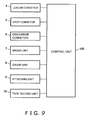
- Fig. 9 is a block diagram showing the connection relationship between a control unit 100 of the strip pack apparatus 1 and each of the devices.
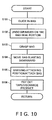
- Fig. 10 is a flowchart showing the control of the strip pack apparatus 1.
- control unit 100 of the strip pack apparatus 1 is connected to each of the conveyors 4 to 6, and each of the units 7 to 10, and is able to receive and send various signals.
- the control of the strip pack apparatus 1 through the control unit 100 will be described below using Fig. 10 .
- a bag X is guided in by the lead-in conveyor 4 to the grasp position P1 (Step S101), and dewrinkling of the seal portion Z of the bag X is performed by the brush unit 7 (Step S 102). Then, the bag X is held by the grasp unit 8 (Step S 103). After that, the bag X is moved slantingly downward on the front side of the conveying direction b (Step S 104). When the bag X reaches the attaching position P2, the attaching unit 9 attaches the bag X to the tape T (Step S105). Then, the tape feeding unit 10 pays out the tape T, and the strip pack SP, which is the product, is discharged (Step S 106).
- the bag X does not have to be moved up by the grasp unit (moving means) 8 like when the attaching position P2 is arranged above the lead-in conveyor 4, and furthermore, the width of the strip pack apparatus 1 does not increase like when the attaching position P2 is arranged to the side of the lead-in conveyor 4, and also, the mechanisms and operations for moving the bag X to the attaching position P2 do not become complicated like when the attaching position P2 is arranged directly below the lead-in conveyor 4.
- the bag X when the bag X is moved from the lead-in conveyor 4 slantingly downward on the front side in the arrow b direction, without having to go through the trouble of removing the lead-in conveyor 4, the bag X can be moved to the attaching position P2, and as a result, the speed of the strip pack apparatus 1 can be increased.
- the grasp unit 8 that moves the bags X to the attaching position P2 is not only used as the moving means, but also used as the grasp means for holding the bags X ( Fig. 4 ). Consequently, the configuration of the strip pack apparatus 1 is simplified.
- the grasp unit 8 used as the grasp means holds the seal portions Z of bags X to be attached to the tape T ( Fig. 8 ). By doing so, the seal portions Z are kept flat. Consequently, the seal portions Z overlap with the tape T favorably, and the bags X are attached to the tape T in a favorable state.
- the drop conveyor (terminal end portion of the conveying means) 5 tilts so that the front side thereof in the arrow b direction (conveying direction) becomes lower ( Fig. 4 ), the bag X is moved smoothly slantingly downward, and also, this prevents a great impact from acting on the bags X when they are being moved.
- the strip pack apparatus 1 described above is independent from both the devices on the upstream side and downstream side, but, for example, it may be integrated with the device on the upstream side or the device on the downstream side.
- the seal portions Z may be held from the sides of the bags X like the pair of grip fingers 81 shown in chained line in Figs. 5 and 8 . By doing so, not only the portion near the portion being dewrinkled by the brush unit 7 can be held, but also the seal portions Z being held will not fall off easily from the pair of grip fingers 81.
Landscapes
- Engineering & Computer Science (AREA)
- Mechanical Engineering (AREA)
- Auxiliary Devices For And Details Of Packaging Control (AREA)
- Package Closures (AREA)
Abstract
Description
- The present invention is in the technical field of manufacturing a product called strip pack, in which a plurality of items is adhered to a backing sheet and displayed in a state of being suspended.
- As is conventional, products in which a plurality of items, which snacks and the like are filled in a bag, are adhered to a backing sheet in a strip and the like, are known. This kind of a product is displayed in retail stores and so forth in a suspended state with a portion of the backing sheet being held in place, and is referred to as strip pack (meaning a packaging configuration in which an item can be taken by pulling it off) since consumers take each individual item by pulling it off from the backing sheet. This strip pack has an advantage of increasing consumers' eagerness to buy, and can promote diversity in the design and space saving of the display.
- A strip pack apparatus for manufacturing this kind of strip pack includes, for example, the apparatus described in
Patent Document 1, which is arranged directly below a vertical bag-making packaging machine, in which after an item manufactured at the packaging machine is moved by a left and right pair of grasping arms grasping the item at the upper two sides thereof to the adhering position below, the item is adhered to the backing sheet at the upper end portion thereof. In addition, the apparatus described inPatent Document 2 is also arranged directly below a vertical bag-making packaging machine, and after an item manufactured at the packaging machine is grasped and held at the upper single surface thereof by a suction cup and moved to the adhering position in front, the item is adhered to the backing sheet at the upper end portion thereof. - Patent Document 1: Japanese Patent Laid-Open Publication No.
2004-182302 - Patent Document 2:
U.S. Patent No. 3864895 Specification - Meanwhile, the strip pack apparatuses described in
Patent Documents - In that case, a problem arises of where to arrange the attaching position with respect to the conveying means. If the attaching position is arranged above the conveying means, the moving means will have to move the item up, which is not commonly done. If the attaching position is arranged to the side of the conveying means, the item will have to be moved to the side, and the width of the strip pack apparatus increases, which deteriorates the layout ability thereof. In that respect, if the attaching position is arranged below the conveying means, it is only necessary for the moving means to move the item downward, and in addition, this does not increase the width of the strip pack apparatus. However, a problem occurs when the attaching position is arranged directly below the conveying means. In order to move the item to the attaching position that is directly below it, it becomes necessary to have a configuration for removing the conveying means since the conveying means will be in the way, and so mechanisms and operations for doing so will be complicated, and the speed cannot be increased.
- Consequently, the present invention has an object of improving the disposition of the attaching position with respect to the conveying means, in a highly versatile strip pack apparatus configured independently from the devices on the upstream side and downstream side thereof, so that an item does not have to be moved up by the moving means, and the width of the strip pack apparatus does not increase, and also, the mechanisms and operations for moving an item to the attaching position do not become complicated.
- The strip pack apparatus, for manufacturing a product with items attached on a backing sheet, according to a first aspect of the present invention for achieving the above described object includes a conveying means for conveying an item roughly in the horizontal direction, a moving means for moving the item conveyed by this conveying means slantingly downward on the front side in the conveying direction from the conveying means, and an attaching means for attaching the item moved by this moving means to a backing sheet.
- The strip pack apparatus according to a second aspect of the present invention is the strip pack apparatus as set forth in the first aspect, wherein the moving means grasps the end portion on the front side in the conveying direction of the item conveyed by the conveying means, and moves the item slantingly downward, and the attaching means attaches the item to a backing sheet at the end portion grasped by the moving means.
- The strip pack apparatus according to a third aspect of the present invention is the strip pack apparatus as set forth in the first or the second aspect, wherein the conveying means conveys the item to a terminal end portion of the conveying means, and the terminal end portion of the conveying means tilts so that the front side in the conveying direction becomes lower when the item is moved by the moving means.
- With the strip pack apparatus according to the first aspect of the present invention, since the strip pack apparatus does not move the item conveyed by the conveying means directly below from the conveying means, but moves the item slantingly downward on the front side in the conveying direction from the conveying means, in other words, since the attaching position is arranged in a position slanting downward on the front side in the conveying direction with respect to the conveying means, the item does not have to be moved up by the moving means like when the attaching position is arranged above the conveying means, and the width of the strip pack apparatus does not increase like when the attaching position is arranged to the side of the conveying means, and also, the mechanisms and operations for moving the item to the attaching position do not become complicated like when the attaching position is arranged directly below the conveying means. In other words, when the item is moved slantingly downward on the front side in the conveying direction from the conveying means, the item can be moved to the attaching position without having to go through the trouble of removing the conveying means, and as a result, the speed of the strip pack apparatus can be increased.
- With the strip pack apparatus according to the second aspect of the present invention, since the moving means for moving the item to the attaching position is also used as the grasp means for holding the item, the configuration of the strip pack apparatus is simplified. In addition, in this case, the moving means, which is the grasp means, holds the end portion of the item to be attached to the backing sheet, and thus, the end portion is kept to be flat. As a result, the end portion overlaps favorably with the backing sheet, and the item is attached to the backing sheet in a favorable state.
- With the strip pack apparatus according to the third aspect of the present invention, since the terminal end portion of the conveying means tilts so that the front side in the conveying direction becomes lower, the item is moved smoothly slantingly downward, and this prevents a big impact from acting on the item when it is being moved.
- The objects, characteristics, aspects, and advantages of this invention will become even more clear with the detailed description below and the attached drawings.
-
-
Fig. 1 is a perspective view showing a strip pack apparatus according to an embodiment of the present invention; -
Fig. 2 is a side view showing the strip pack apparatus; -
Fig. 3(a) is a plan view showing a bag to be supplied to the strip pack apparatus; -
Fig. 3(b) is a plan view showing a strip pack manufactured by the strip pack apparatus; -
Fig. 4 is a side view showing the positional relationship between a grasp position and an attaching position in the strip pack apparatus; -
Fig. 5 is a plan view showing the state when dewrinkling a seal portion of a bag, and when the seal portion is being held; -
Fig. 6(a) is a side view showing the state before the seal portion of a bag is grasped by the grasp unit; -
Fig. 6(b) is a side view showing the state after the seal portion of a bag is grasped by the grasp unit; -
Fig. 7 is a side view showing an attaching unit; -
Fig. 8 is a plan view showing the state when attaching a bag to a tape; -
Fig. 9 is a diagram showing a control system of the strip pack apparatus; and -
Fig. 10 is a diagram showing the flow of the operations of the strip pack apparatus. -
Figs. 1 and2 show a perspective view and a side view respectively, conceptually showing astrip pack apparatus 1 according to an embodiment of the present invention.Fig. 4 shows the flow of a series of processes, from a process of guiding a packaged item (bag X) to the interior of thestrip pack apparatus 1, to a process of attaching the packaged item to a tape T. -
Figs. 3(a) and 3(b) show the packaged item (bag X) and the strip pack SP, respectively. The bag X has a hollow portion Y in which snacks and the like are filled, and two seal portions Z at the top and bottom (Fig. 3(a) ). In addition, the top seal portion Z refers to the side of the seal portion Z on which the letters "SNACK" written on the bag can be read from a normal viewpoint, when one of the two seal portions Z is picked and lifted up. - In the strip pack SP, a predetermined number of bags X are aligned and attached on the tape T (
Fig. 3(b) ). The top seal portions Z of the bags X are attached to the tape T. A hole punched is provided on a portion near an end of the tape T for allowing the strip pack SP to be displayed suspended. - The
strip pack apparatus 1 having great versatility is an apparatus for manufacturing strip packs SP, and is independent from both the devices on the upstream and downstream sides. Furthermore, a packaging unit and the like for filling articles into the bags X through automatic packaging are included in the device on the upstream side. A device and the like for putting the strip packs SP into a box are included in the device on the downstream side. - Specifically, the
strip pack apparatus 1 includes abody unit 2, asupply conveyor 3, a lead-inconveyor 4, adrop conveyor 5, adischarge conveyor 6, abrush unit 7, agrasp unit 8, an attachingunit 9, and atape feeding unit 10. - The
supply conveyor 3, the lead-inconveyor 4, thedrop conveyor 5, thedischarge conveyor 6, thebrush unit 7, thegrasp unit 8, the attachingunit 9, and thetape feeding unit 10 are supported by thebody unit 2. - Each device will be described in detail below.
- The
supply conveyor 3 supplies the bags X produced at the device on the upstream side to thestrip pack apparatus 1. More specifically, thesupply conveyor 3 is arranged outside thestrip pack apparatus 1, and conveys the bags X in the direction roughly horizontal, and in the direction of arrow a (Fig. 2 ). - The lead-in
conveyor 4 guides the bags X supplied by thesupply conveyor 3 to the interior of thestrip pack apparatus 1. More specifically, the lead-inconveyor 4 conveys the bags X in a direction roughly horizontal, and in the direction of arrow b (Fig. 2 ). At this time, the bags X are conveyed in the direction of arrow b with the top seal portions Z to the front. The arrow b direction is the opposite direction from the arrow a direction. - The lead-in
conveyor 4 can be comprehended to be the conveying means for conveying bags X roughly in the horizontal direction, in view of the lead-inconveyor 4 conveying bags X roughly in the horizontal direction. In addition, the arrow b direction can be comprehended as the conveying direction. - A
member 12 is arranged on the starting end portion side of the lead-inconveyor 4 that conveys the bags X in the arrow b direction (Fig. 2 ). Themember 12 prevents the bags X, dropped from thesupply conveyor 3, from not being entered into thestrip pack apparatus 1. Furthermore, themember 12 is omitted inFig. 1 . - The
drop conveyor 5 is positioned on the terminal end portion side of the lead-inconveyor 4, and guides the bags X conveyed by the lead-inconveyor 4 to thebrush unit 7. In addition, the conveying means described above can include thedrop conveyor 5. When this is the case, thedrop conveyor 5 can be comprehended to be the terminal end portion of the conveying means. - As shown in
Fig. 4 , thedrop conveyor 5 can move in the arrow e direction with a fulcrum 51 as the center thereof. Thedrop conveyor 5 tilts with the movement thereof in the arrow e direction. - The movement of the
drop conveyor 5 is linked to the movement of thegrasp unit 8. This is described in detail in "GraspUnit 8". - The
brush unit 7 undoes the wrinkles on the top seal portions Z of the bags X being conveyed thereto by thedrop conveyor 5. Details will be described usingFig. 5 . -
Fig. 5 is a diagram of thebrush unit 7 viewed from above. Thebrush unit 7 is arranged on the distant side of the arrow b with respect to the drop conveyor 5 (Fig. 4 ), and includes two of each of thebrushes 72 and supportingmembers 71. In addition, only theupper brush 72 and the supportingmember 71 for supporting theupper brush 72 are shown inFig. 5 . - The
brushes 72 undo wrinkles on the seal portions Z of bags X. More specifically, thebrush unit 7 includes twobrushes 72 for sandwiching the seal portion Z from the upper side and the lower side. With both the upper and the lower brushes 72, a plurality of thin disk-shaped separated brushes is arranged side by side at predetermined intervals. Spongious brushes, brushes like scrubbing brushes with wire rods tied together radially, and the like, can be adopted for thebrushes 72. - The
upper brush 72 rotates from the base portion side to the edge portion side of the seal portion Z, in the state of being in contact with the upper surface of the seal portion Z. Thelower brush 72 rotates from the base portion side to the edge portion side of the seal portion Z, in the state of being in contact with the under surface of the seal portion Z. By doing so, the top seal portion Z is dewrinkled by being stroked by the upper and lower two brushes 72. - In addition, the upper and
lower brushes 72 are supported by the supportingmembers 71 arranged one at the top and one at the bottom, respectively. -
Fig. 6 shows thegrasp unit 8 viewed from the side. The configuration and the operation of thegrasp unit 8 and the positional relationship thereof with thebrush unit 7 will be described below usingFigs. 6 and4 . - The
grasp unit 8 grasps the top seal portions Z of the bags X dewrinkled by thebrush unit 7 from the top seal portion Z side (distant side of arrow b) with respect to the bags X. More specifically, thegrasp unit 8 is arranged on the distant side of the arrow b with respect to thedrop conveyor 5, and includes a pair ofgrip fingers 81, hands 82,arms 83, and guide rails 84 (Fig. 4 ). - The pair of
grip fingers 81 is arranged one on the upper side and the other on the lower side, and can grasp the seal portions Z by sandwiching the seal portions Z from above and below. This pair ofgrip fingers 81 each includes afinger body 81a and agrasp portion 81b. Thefinger bodies 81a can move (pivot) in the arrow f direction (Fig. 6 ), withfulcrums 82a provided on thehand 82 as the centers thereof. - The
grasp portions 81b are mounted on the tip of thefinger bodies 81a. Rubber and the like, having elasticity, is adopted for thegrasp portions 81 b. By doing so, it becomes easier to grasp the seal portions Z, and as a result, it can prevent the seal portions Z from falling off from between the upper andlower grasp portions 81 b after being grasped. - The
hands 82 are supported on thearms 83, and are both equipped with the pair of grip fingers 81 (Fig. 4 ). Thehands 82 can adjust the positions thereof relative to thearms 83. Thearms 83 can move along the tilted guide rails 84. - On the two sides of the
brush unit 7 are each of thegrip fingers 81, and thehands 82 as well, for these grip fingers 81 (Fig. 5 ). - The
grip fingers 81, one on each side, on both sides of thebrush unit 7 grasps the seal portions Z longitudinally at the two sides of thebrushes 72. Consequently, wrinkles on the portion of the seal portions Z between the twogrip fingers 81 are undone by thebrush unit 7. - The
grasp unit 8 holds the seal portions Z after the seal portions Z have been dewrinkled by thebrush unit 7 at position (grasp position) P1 near the terminal end portion of thedrop conveyor 5. - After that, the
grasp unit 8 moves in the arrow d (Fig. 4 ) direction, more specifically, on distant side (front side) of arrow b (Fig. 4 ), and to the direction slanting downward. As a result, the bag X being grasped moves to the attachingunit 9, more specifically, to position (attaching position) P2. - When moving the bag X in the arrow d direction, the
drop conveyor 5 moves in the arrow e (Fig. 4 ) direction, and tilts. - The
grasp unit 8 holds the bag X conveyed thereto by the lead-inconveyor 4, and moves this bag X, while holding the bag X, to the front side of arrow b, and to the direction slanting downward. In view of this, thegrasp unit 8 can be comprehended in the following way. In other words, thegrasp unit 8 can be comprehended to be the grasp means for holding bags X, and can be comprehended to be the moving means for moving the bag X conveyed by the lead-in conveyor (conveying means) 4 from the lead-inconveyor 4 slantingly downward on the front side of the arrow b direction (conveying direction). - The attaching
unit 9 attaches the top seal portion Z of the bag X held by thegrasp unit 8 to the tape T. In addition, the attachingunit 8 can be comprehended to be the attaching means for attaching bags X to the tape T. The details will be described usingFigs. 7 and8 . -
Fig. 7 is a diagram of the attachingunit 9 viewed from the side.Fig. 8 is a diagram of the attachingunit 9 viewed from above. The attachingunit 9 includes aheater 91, aclamp 92, aclamp air cylinder 93, a punch/cutter unit 94, amelting prevention member 95, and anair cylinder 96. Theheater 91 is the source of heat used for adhering the bags X and the tape T. - The
clamp 92, able to move up and down, sandwiches the bags X and the tape T together with theheater 91, and is able to press the bags X against the tape T. The up and down movement of theclamp 92 is executed by theclamp air cylinder 93. - The punch/
cutter unit 94 can properly punch holes and put in perforations on the tape T. - The
melting prevention member 95 prevents the tape T from being melted by raising the tape T up from theheater 91, with the upward movement thereof. The up and down movement of themelting prevention member 95 is executed by theair cylinder 96. - The operation of the attaching
unit 9 will now be described. First, in the state of theclamp 92 being moved to the top, tape T paid out from aroll 11 is placed on theheater 91. The top seal portion Z of the bag X moved to the position P2 by thegrasp unit 8 is being overlapped with the tape T on theheater 91. - The tape T and the seal portion Z are sandwiched by the downward movement of the
clamp 92, and the seal portion Z is being pressed against the tape T. By doing so, the seal portion Z adheres to the tape T with the heat from theheater 91. Furthermore, the region of the seal portion Z being adhered to the tape T is shown by the matching area R inFig. 8 . - The attaching
unit 9 repeats the adhering of the bags X, and adheres a plurality of bags X on this strip of tape T along the longitudinal direction thereof. - The strip pack SP manufactured by a predetermined number of bags X being attached is being received at the tilted
receiver 13, and guided to the discharge conveyor 6 (Fig. 2 ). Note that thereceiver 13 is omitted inFig. 1 . - The
discharge conveyor 6 discharges the strip packs SP manufactured at thestrip pack apparatus 1 to a device on the downstream side. More specifically, thedischarge conveyor 6 conveys the strip packs SP to the arrow c direction (Fig. 2 ). - The
tape feeding unit 10 pays out the tape T from theroll 11 in synchronism with the manufacturing of the strip pack SP. In addition, theroll 11 is arranged on the upper side of thebody unit 2, and can be exchanged. -
Fig. 9 is a block diagram showing the connection relationship between acontrol unit 100 of thestrip pack apparatus 1 and each of the devices.Fig. 10 is a flowchart showing the control of thestrip pack apparatus 1. - As shown in
Fig. 9 , thecontrol unit 100 of thestrip pack apparatus 1 is connected to each of theconveyors 4 to 6, and each of theunits 7 to 10, and is able to receive and send various signals. The control of thestrip pack apparatus 1 through thecontrol unit 100 will be described below usingFig. 10 . - First, a bag X is guided in by the lead-in
conveyor 4 to the grasp position P1 (Step S101), and dewrinkling of the seal portion Z of the bag X is performed by the brush unit 7 (Step S 102). Then, the bag X is held by the grasp unit 8 (Step S 103).
After that, the bag X is moved slantingly downward on the front side of the conveying direction b (Step S 104). When the bag X reaches the attaching position P2, the attachingunit 9 attaches the bag X to the tape T (Step S105). Then, thetape feeding unit 10 pays out the tape T, and the strip pack SP, which is the product, is discharged (Step S 106).
With thestrip pack apparatus 1 described above, since the bag X conveyed by the lead-in conveyor (conveying means) 4 is not moved directly below from the lead-inconveyor 4, but moved slantingly downward on the front side in the arrow b direction (conveying direction) from the lead-inconveyor 4, in other words, since the attaching position P2 is arranged in a position that is slanted downward on the front side in the arrow b direction away from the lead-in conveyor 4 (Fig. 4 ), for example, the bag X does not have to be moved up by the grasp unit (moving means) 8 like when the attaching position P2 is arranged above the lead-inconveyor 4, and furthermore, the width of thestrip pack apparatus 1 does not increase like when the attaching position P2 is arranged to the side of the lead-inconveyor 4, and also, the mechanisms and operations for moving the bag X to the attaching position P2 do not become complicated like when the attaching position P2 is arranged directly below the lead-inconveyor 4. In other words, when the bag X is moved from the lead-inconveyor 4 slantingly downward on the front side in the arrow b direction, without having to go through the trouble of removing the lead-inconveyor 4, the bag X can be moved to the attaching position P2, and as a result, the speed of thestrip pack apparatus 1 can be increased. - In addition, the
grasp unit 8 that moves the bags X to the attaching position P2 is not only used as the moving means, but also used as the grasp means for holding the bags X (Fig. 4 ). Consequently, the configuration of thestrip pack apparatus 1 is simplified. In addition, thegrasp unit 8 used as the grasp means holds the seal portions Z of bags X to be attached to the tape T (Fig. 8 ). By doing so, the seal portions Z are kept flat. Consequently, the seal portions Z overlap with the tape T favorably, and the bags X are attached to the tape T in a favorable state. - In addition, since the drop conveyor (terminal end portion of the conveying means) 5 tilts so that the front side thereof in the arrow b direction (conveying direction) becomes lower (
Fig. 4 ), the bag X is moved smoothly slantingly downward, and also, this prevents a great impact from acting on the bags X when they are being moved. - The
strip pack apparatus 1 described above is independent from both the devices on the upstream side and downstream side, but, for example, it may be integrated with the device on the upstream side or the device on the downstream side. - The seal portions Z may be held from the sides of the bags X like the pair of
grip fingers 81 shown in chained line inFigs. 5 and8 . By doing so, not only the portion near the portion being dewrinkled by thebrush unit 7 can be held, but also the seal portions Z being held will not fall off easily from the pair ofgrip fingers 81. - This invention was described in detail, but all of the situations described above are exemplifications that are not intended for limiting this invention. It is possible to think of an infinite number of examples of modifications that are not illustrated, and that do not deviate from the scope of this invention.
Claims (3)
- A strip pack apparatus for manufacturing a product with items attached on a backing sheet, comprising:a conveying means for conveying an item roughly in the horizontal direction;a moving means for moving the item, conveyed by this conveying means, slantingly downward on the front side in the conveying direction from the conveying means; andan attaching means for attaching the item moved by this moving means to a backing sheet.
- The strip pack apparatus according to Claim 1, whereinthe moving means grasps an end portion on the front side in the conveying direction of the item conveyed by the conveying means, and moves the item slantingly downward, andthe attaching means attaches the item to a backing sheet at the end portion grasped by the moving means.
- The strip pack apparatus according to Claim 1 or Claim 2, whereinthe conveying means conveys the item to a terminal end portion of the conveying means, andthe terminal end portion of the conveying means tilts so that the front side in the conveying direction becomes lower when the item is moved by the moving means.
Applications Claiming Priority (2)
| Application Number | Priority Date | Filing Date | Title |
|---|---|---|---|
| JP2006289937A JP5139663B2 (en) | 2006-10-25 | 2006-10-25 | Strip pack equipment |
| PCT/JP2007/069386 WO2008050593A1 (en) | 2006-10-25 | 2007-10-03 | Strip-pack apparatus |
Publications (2)
| Publication Number | Publication Date |
|---|---|
| EP2088083A1 true EP2088083A1 (en) | 2009-08-12 |
| EP2088083A4 EP2088083A4 (en) | 2012-11-14 |
Family
ID=39324399
Family Applications (1)
| Application Number | Title | Priority Date | Filing Date |
|---|---|---|---|
| EP07829125A Withdrawn EP2088083A4 (en) | 2006-10-25 | 2007-10-03 | Strip-pack apparatus |
Country Status (7)
| Country | Link |
|---|---|
| US (1) | US8047249B2 (en) |
| EP (1) | EP2088083A4 (en) |
| JP (1) | JP5139663B2 (en) |
| CN (1) | CN101528547B (en) |
| AU (1) | AU2007310277A1 (en) |
| BR (1) | BRPI0721475A2 (en) |
| WO (1) | WO2008050593A1 (en) |
Families Citing this family (2)
| Publication number | Priority date | Publication date | Assignee | Title |
|---|---|---|---|---|
| EP3506340B1 (en) * | 2017-12-28 | 2020-10-21 | Nexperia B.V. | Bonding and indexing apparatus |
| JP6836282B2 (en) * | 2019-06-03 | 2021-02-24 | スキューズ株式会社 | Article holding method, article holding device and article transfer device |
Family Cites Families (18)
| Publication number | Priority date | Publication date | Assignee | Title |
|---|---|---|---|---|
| US3465411A (en) * | 1967-08-21 | 1969-09-09 | George R Mahnken | Envelope attaching apparatus and method |
| US3864895A (en) * | 1973-02-26 | 1975-02-11 | Wright Machinery Company Inc | Multi-pack method and apparatus |
| US4476619A (en) * | 1982-06-15 | 1984-10-16 | Palmer Systems, Incorporated | Method and apparatus for inserting bags onto cards |
| JPS60154206U (en) * | 1984-03-27 | 1985-10-15 | オリヒロ株式会社 | Horizontal seal wrinkle prevention device |
| JPH0112715Y2 (en) * | 1985-12-18 | 1989-04-13 | ||
| JPH02310208A (en) * | 1989-05-26 | 1990-12-26 | Mamoru Matsubara | Multilayer conveyor system for article |
| DE3938410A1 (en) * | 1989-11-18 | 1991-05-23 | Focke & Co | DEVICE FOR APPLYING AN ADHESIVE STRIP TO A FOLDING CARDBOARD OR THE LIKE |
| JP2557818Y2 (en) * | 1992-04-28 | 1997-12-17 | 三菱瓦斯化学株式会社 | Apparatus for fixing small bags in hot melt adhesive |
| JPH08258961A (en) * | 1995-03-22 | 1996-10-08 | Yamazaki Baking Co Ltd | Transfer direction changing method of transfer conveyor and its transfer device |
| JPH1111442A (en) * | 1997-06-20 | 1999-01-19 | Ishida Co Ltd | Packaging equipment |
| US6726794B2 (en) * | 2001-03-15 | 2004-04-27 | Rudolph Foods Company, Inc. | Apparatus and method for producing a merchandiser and a pre-loaded merchandiser produced thereby |
| NL1018425C2 (en) * | 2001-06-29 | 2003-01-07 | Food Processing Systems | Device for delivering substantially spherical products in a substantially rectangular holder. |
| US20040025329A1 (en) * | 2002-08-07 | 2004-02-12 | Belt James G. | Apparatus and method for producing a pre-loaded display strip |
| US7093404B2 (en) * | 2002-08-29 | 2006-08-22 | Ishida Co., Ltd. | Bag manufacturing and packaging apparatus |
| US6976350B2 (en) * | 2002-10-18 | 2005-12-20 | Boss Packaging Inc. | Bag presenter for a packaging machine |
| JP2004182302A (en) * | 2002-12-04 | 2004-07-02 | Ishida Co Ltd | Band mounting device and bag making and packaging machine |
| JP2005200039A (en) * | 2004-01-14 | 2005-07-28 | Ishida Co Ltd | Tape mounting system |
| JP4619648B2 (en) * | 2003-12-03 | 2011-01-26 | 株式会社イシダ | Strip bag equipment |
-
2006
- 2006-10-25 JP JP2006289937A patent/JP5139663B2/en not_active Expired - Fee Related
-
2007
- 2007-10-03 EP EP07829125A patent/EP2088083A4/en not_active Withdrawn
- 2007-10-03 AU AU2007310277A patent/AU2007310277A1/en not_active Abandoned
- 2007-10-03 CN CN200780039641.6A patent/CN101528547B/en not_active Expired - Fee Related
- 2007-10-03 BR BRPI0721475-8A patent/BRPI0721475A2/en not_active IP Right Cessation
- 2007-10-03 US US12/447,167 patent/US8047249B2/en not_active Expired - Fee Related
- 2007-10-03 WO PCT/JP2007/069386 patent/WO2008050593A1/en not_active Ceased
Also Published As
| Publication number | Publication date |
|---|---|
| JP2008105702A (en) | 2008-05-08 |
| BRPI0721475A2 (en) | 2014-03-25 |
| EP2088083A4 (en) | 2012-11-14 |
| US8047249B2 (en) | 2011-11-01 |
| CN101528547B (en) | 2011-04-20 |
| AU2007310277A1 (en) | 2008-05-02 |
| WO2008050593A1 (en) | 2008-05-02 |
| US20100024988A1 (en) | 2010-02-04 |
| JP5139663B2 (en) | 2013-02-06 |
| CN101528547A (en) | 2009-09-09 |
Similar Documents
| Publication | Publication Date | Title |
|---|---|---|
| US6481184B1 (en) | Method and apparatus for fastening of tubular bags on a hanger strip | |
| JP2002037206A (en) | Vertical bag making and packaging machine | |
| CN209064521U (en) | Packing machine and packaging stacked body | |
| US8047249B2 (en) | Strip pack apparatus | |
| CN101321668A (en) | Devices for packaging small products | |
| AU2007310276B2 (en) | Strip pack apparatus, and grasper and dewrinkler used therein | |
| JP5432216B2 (en) | Method and apparatus for supplying attached document in boxing machine | |
| CN101715412A (en) | Packaging plant comprising at least two combined vertical forming tubes | |
| EP2143644A1 (en) | Strip pack equipment | |
| JP4857062B2 (en) | Vertical bag making filling and packaging machine for square bottom bags | |
| JP4577918B2 (en) | Ampoule bagging equipment | |
| JP2004115082A (en) | Product display equipment and display equipment processing equipment | |
| JP4841380B2 (en) | Vertical bag making filling and packaging machine for square bottom bags | |
| JP5059375B2 (en) | Strip pack equipment | |
| EP4382435B1 (en) | Bagmaking and packaging apparatus | |
| JP6516526B2 (en) | Container cleaning device | |
| JP2007168874A (en) | Sheet take-out device and packing device | |
| JP3805542B2 (en) | Card feeding device and feeding method | |
| JP4994783B2 (en) | Kneading and stretching device used in strip pack device and strip pack device using the same | |
| JP4994784B2 (en) | Strip pack equipment | |
| JP4264712B2 (en) | Method and apparatus for combining continuous straw packaging with sheet pieces | |
| JP4994785B2 (en) | Strip pack equipment | |
| US20100223885A1 (en) | Strip- pack manufacturing apparatus | |
| JP2011230801A (en) | Strip pack manufacturing apparatus | |
| JP2008100722A (en) | Package separating apparatus |
Legal Events
| Date | Code | Title | Description |
|---|---|---|---|
| PUAI | Public reference made under article 153(3) epc to a published international application that has entered the european phase |
Free format text: ORIGINAL CODE: 0009012 |
|
| 17P | Request for examination filed |
Effective date: 20090522 |
|
| AK | Designated contracting states |
Kind code of ref document: A1 Designated state(s): AT BE BG CH CY CZ DE DK EE ES FI FR GB GR HU IE IS IT LI LT LU LV MC MT NL PL PT RO SE SI SK TR |
|
| DAX | Request for extension of the european patent (deleted) | ||
| A4 | Supplementary search report drawn up and despatched |
Effective date: 20121015 |
|
| RIC1 | Information provided on ipc code assigned before grant |
Ipc: B65B 15/04 20060101AFI20121009BHEP |
|
| 17Q | First examination report despatched |
Effective date: 20130531 |
|
| STAA | Information on the status of an ep patent application or granted ep patent |
Free format text: STATUS: THE APPLICATION IS DEEMED TO BE WITHDRAWN |
|
| 18D | Application deemed to be withdrawn |
Effective date: 20131011 |