EP2086716B1 - Motion control apparatus - Google Patents
Motion control apparatus Download PDFInfo
- Publication number
- EP2086716B1 EP2086716B1 EP07844642A EP07844642A EP2086716B1 EP 2086716 B1 EP2086716 B1 EP 2086716B1 EP 07844642 A EP07844642 A EP 07844642A EP 07844642 A EP07844642 A EP 07844642A EP 2086716 B1 EP2086716 B1 EP 2086716B1
- Authority
- EP
- European Patent Office
- Prior art keywords
- piston
- brake
- linear motion
- shoe
- extending
- Prior art date
- Legal status (The legal status is an assumption and is not a legal conclusion. Google has not performed a legal analysis and makes no representation as to the accuracy of the status listed.)
- Not-in-force
Links
- 239000012530 fluid Substances 0.000 claims description 13
- 230000002195 synergetic effect Effects 0.000 description 3
- 230000006835 compression Effects 0.000 description 2
- 238000007906 compression Methods 0.000 description 2
- 238000010276 construction Methods 0.000 description 2
- 230000009286 beneficial effect Effects 0.000 description 1
- 238000004891 communication Methods 0.000 description 1
- 230000007812 deficiency Effects 0.000 description 1
- 230000001419 dependent effect Effects 0.000 description 1
- 238000004519 manufacturing process Methods 0.000 description 1
- 238000000034 method Methods 0.000 description 1
- 235000012771 pancakes Nutrition 0.000 description 1
- 238000007789 sealing Methods 0.000 description 1
- 239000004065 semiconductor Substances 0.000 description 1
Images



Classifications
-
- B—PERFORMING OPERATIONS; TRANSPORTING
- B23—MACHINE TOOLS; METAL-WORKING NOT OTHERWISE PROVIDED FOR
- B23Q—DETAILS, COMPONENTS, OR ACCESSORIES FOR MACHINE TOOLS, e.g. ARRANGEMENTS FOR COPYING OR CONTROLLING; MACHINE TOOLS IN GENERAL CHARACTERISED BY THE CONSTRUCTION OF PARTICULAR DETAILS OR COMPONENTS; COMBINATIONS OR ASSOCIATIONS OF METAL-WORKING MACHINES, NOT DIRECTED TO A PARTICULAR RESULT
- B23Q1/00—Members which are comprised in the general build-up of a form of machine, particularly relatively large fixed members
- B23Q1/25—Movable or adjustable work or tool supports
- B23Q1/26—Movable or adjustable work or tool supports characterised by constructional features relating to the co-operation of relatively movable members; Means for preventing relative movement of such members
- B23Q1/28—Means for securing sliding members in any desired position
-
- F—MECHANICAL ENGINEERING; LIGHTING; HEATING; WEAPONS; BLASTING
- F15—FLUID-PRESSURE ACTUATORS; HYDRAULICS OR PNEUMATICS IN GENERAL
- F15B—SYSTEMS ACTING BY MEANS OF FLUIDS IN GENERAL; FLUID-PRESSURE ACTUATORS, e.g. SERVOMOTORS; DETAILS OF FLUID-PRESSURE SYSTEMS, NOT OTHERWISE PROVIDED FOR
- F15B15/00—Fluid-actuated devices for displacing a member from one position to another; Gearing associated therewith
- F15B15/20—Other details, e.g. assembly with regulating devices
- F15B15/26—Locking mechanisms
- F15B15/262—Locking mechanisms using friction, e.g. brake pads
-
- B—PERFORMING OPERATIONS; TRANSPORTING
- B23—MACHINE TOOLS; METAL-WORKING NOT OTHERWISE PROVIDED FOR
- B23Q—DETAILS, COMPONENTS, OR ACCESSORIES FOR MACHINE TOOLS, e.g. ARRANGEMENTS FOR COPYING OR CONTROLLING; MACHINE TOOLS IN GENERAL CHARACTERISED BY THE CONSTRUCTION OF PARTICULAR DETAILS OR COMPONENTS; COMBINATIONS OR ASSOCIATIONS OF METAL-WORKING MACHINES, NOT DIRECTED TO A PARTICULAR RESULT
- B23Q5/00—Driving or feeding mechanisms; Control arrangements therefor
- B23Q5/22—Feeding members carrying tools or work
-
- F—MECHANICAL ENGINEERING; LIGHTING; HEATING; WEAPONS; BLASTING
- F16—ENGINEERING ELEMENTS AND UNITS; GENERAL MEASURES FOR PRODUCING AND MAINTAINING EFFECTIVE FUNCTIONING OF MACHINES OR INSTALLATIONS; THERMAL INSULATION IN GENERAL
- F16D—COUPLINGS FOR TRANSMITTING ROTATION; CLUTCHES; BRAKES
- F16D63/00—Brakes not otherwise provided for; Brakes combining more than one of the types of groups F16D49/00 - F16D61/00
-
- F—MECHANICAL ENGINEERING; LIGHTING; HEATING; WEAPONS; BLASTING
- F16—ENGINEERING ELEMENTS AND UNITS; GENERAL MEASURES FOR PRODUCING AND MAINTAINING EFFECTIVE FUNCTIONING OF MACHINES OR INSTALLATIONS; THERMAL INSULATION IN GENERAL
- F16D—COUPLINGS FOR TRANSMITTING ROTATION; CLUTCHES; BRAKES
- F16D63/00—Brakes not otherwise provided for; Brakes combining more than one of the types of groups F16D49/00 - F16D61/00
- F16D63/008—Brakes acting on a linearly moving member
-
- F—MECHANICAL ENGINEERING; LIGHTING; HEATING; WEAPONS; BLASTING
- F16—ENGINEERING ELEMENTS AND UNITS; GENERAL MEASURES FOR PRODUCING AND MAINTAINING EFFECTIVE FUNCTIONING OF MACHINES OR INSTALLATIONS; THERMAL INSULATION IN GENERAL
- F16D—COUPLINGS FOR TRANSMITTING ROTATION; CLUTCHES; BRAKES
- F16D65/00—Parts or details
- F16D65/14—Actuating mechanisms for brakes; Means for initiating operation at a predetermined position
-
- F—MECHANICAL ENGINEERING; LIGHTING; HEATING; WEAPONS; BLASTING
- F16—ENGINEERING ELEMENTS AND UNITS; GENERAL MEASURES FOR PRODUCING AND MAINTAINING EFFECTIVE FUNCTIONING OF MACHINES OR INSTALLATIONS; THERMAL INSULATION IN GENERAL
- F16D—COUPLINGS FOR TRANSMITTING ROTATION; CLUTCHES; BRAKES
- F16D2121/00—Type of actuator operation force
- F16D2121/02—Fluid pressure
- F16D2121/12—Fluid pressure for releasing a normally applied brake, the type of actuator being irrelevant or not provided for in groups F16D2121/04 - F16D2121/10
-
- F—MECHANICAL ENGINEERING; LIGHTING; HEATING; WEAPONS; BLASTING
- F16—ENGINEERING ELEMENTS AND UNITS; GENERAL MEASURES FOR PRODUCING AND MAINTAINING EFFECTIVE FUNCTIONING OF MACHINES OR INSTALLATIONS; THERMAL INSULATION IN GENERAL
- F16D—COUPLINGS FOR TRANSMITTING ROTATION; CLUTCHES; BRAKES
- F16D2125/00—Components of actuators
- F16D2125/18—Mechanical mechanisms
- F16D2125/20—Mechanical mechanisms converting rotation to linear movement or vice versa
- F16D2125/22—Mechanical mechanisms converting rotation to linear movement or vice versa acting transversely to the axis of rotation
- F16D2125/28—Cams; Levers with cams
-
- F—MECHANICAL ENGINEERING; LIGHTING; HEATING; WEAPONS; BLASTING
- F16—ENGINEERING ELEMENTS AND UNITS; GENERAL MEASURES FOR PRODUCING AND MAINTAINING EFFECTIVE FUNCTIONING OF MACHINES OR INSTALLATIONS; THERMAL INSULATION IN GENERAL
- F16D—COUPLINGS FOR TRANSMITTING ROTATION; CLUTCHES; BRAKES
- F16D2125/00—Components of actuators
- F16D2125/18—Mechanical mechanisms
- F16D2125/58—Mechanical mechanisms transmitting linear movement
- F16D2125/66—Wedges
-
- F—MECHANICAL ENGINEERING; LIGHTING; HEATING; WEAPONS; BLASTING
- F16—ENGINEERING ELEMENTS AND UNITS; GENERAL MEASURES FOR PRODUCING AND MAINTAINING EFFECTIVE FUNCTIONING OF MACHINES OR INSTALLATIONS; THERMAL INSULATION IN GENERAL
- F16D—COUPLINGS FOR TRANSMITTING ROTATION; CLUTCHES; BRAKES
- F16D2127/00—Auxiliary mechanisms
- F16D2127/08—Self-amplifying or de-amplifying mechanisms
- F16D2127/10—Self-amplifying or de-amplifying mechanisms having wedging elements
Definitions
- the present invention generally relates to motion control apparatus and in particular brakes, Specifically, the present invention relates to brakes suitable for use with a track to brake motion such as linear motion, and more specifically relates to linear motion brakes.
- a brake for stopping linearly moving loads is shown in the drawings and generally designated 10.
- Brake 10 in its most preferred form is used with a linear motion device such as a linear stage or motor which can be of any conventional design-
- linear motion device includes a base plate 14 and a sliding plate 16 mounted for linear motion for a distance relative to the base plate 14 such as by two or more linear bearings 18 slideable upon linear races 20 in a linear movement direction.
- Sliding plate 15 is driven relative to the base plate 14 such as by an armature secured to sliding plate 16 which slides through a stationary stator secured to the base plate 14.
- the linear motion device can have a variety of configurations.
- brake 10 may have application to other drives for providing linear motion including but not limited to ball screws, belt drives, air cylinders, and the like.
- Brake 10 generally includes a brake housing 80 secured to sliding plate 16 such as by bolts 82 extending through sliding plate 16 and threaded into housing 80.
- housing 80 is mounted for movement along race 20 in the operation direction.
- housing 80 is in the form of a plate having an upper abutment surface 84 of a square, planar shape for abutment with sliding plate 16.
- Housing 80 includes a lower surface also of a square, planar shape parallel to and spaced from surface 84, with the lower surface including a piston cavity 86 extending therefrom towards but spaced from surface 84.
- An inlet 88 extends from one of the edges of housing 80 and is in fluid communication with cavity 86.
- cavity 86 has generally square cross-sections parallel to surface 84 and sliding plate 16, with the corners of the square cross-sections being rounded to allow fabrication.
- Brake 10 further includes a shoe guide 90 fixedly connected and secured to housing 80.
- guide 90 is in the form of a channel and has generally U-shaped cross-sections.
- guide 90 includes first and second leg plates 92 extending from opposite sides of a connecting plate 94.
- Leg plates 92 are parallel to each other and spaced a distance for receiving race 20 without abutment.
- Shoe bores 95 are formed in each leg plate 92 spaced from and extending parallel to connecting plate 94.
- Connecting plate 94 includes first and second rectangular cut-outs 96 extending between leg plates 92 and located on opposite sides of shoe bores 96.
- shoe guide 90 is secured to housing 80 by bolts 98 extending through connecting plate 94 and threadably received in housing 80 outwardly of piston cavity 86. To avoid interference, the heads of bolts 98 can be countersunk in the lower surface of connecting plate 94.
- Brake 10 further includes a piston 100 reciprocally received in piston cavity 86 for reciprocal movement in a reciprocation direction perpendicular to the operation direction.
- piston 100 includes a head 102 having an outer periphery having cross-sections perpendicular to the operation direction corresponding to and for slideable receipt in piston cavity 86. Suitable sealing 104 is provided between the outer periphery of head 102 and piston cavity 86 such as a quad ring seal as shown.
- Piston 100 is reciprocal between a first operative position and a second operative position outwardly of piston cavity 86 in the reciprocation direction.
- piston 100 has generally U-sHaped cross-sections perpendicular to the operative direction to straddle race 20.
- first and second protrusions 106 extend from head 102 in a parallel relationship and spaced a distance for receiving shoe guide 90 parallel to and without abutment with leg plates 92.
- each protrusion 106 is in the form of a yoke for supporting a cam follower 108 which in the most preferred form is in the form of a roller rotatable about an axis defined by a pin 110 extending through protrusions 106 parallel to and spaced from leg plates 92.
- Piston 100 is biased from the second operative position towards the first operative position into piston cavity 86.
- head 102 includes a multiplicity of spring cavities 112. Compression coil springs 114 partially located in cavities 112 are sandwiched between head 102 and connecting plate 94.
- piston 100 further includes first and second ribs 116 extending in a spaced, parallel relation between protrusions 106 and on opposite sides of spring cavities 112. Ribs 116 are provided for multiple purposes. Specifically, ribs 116 are slideably received in cutouts 96 of shoe guide 90 to maintain piston 100 in position relative to the shoe guide 90 and housing 80 to counteract the counter-forces placed thereon. Further, the presences of ribs 116 allows the thickness of head 102 to be minimized while still maintaining structural integrity to prevent protrusions 106 from separating due to counter-forces placed thereon.
- Brake 10 further includes brake shoes 120 of a size and shape slideably received in shoe bores 96 of shoe guide 90 and for movement in a shoe direction defined by shoe bores 96 and perpendicular to the operative direction, to the reciprocal direction and to race 20.
- each shoe 120 includes an inner interface surface 122 for interfacing with race 20.
- each shoe 120 includes an outer cam surface 124 for engagement by cam follower 108.
- cam surface 124 includes a first planar portion 126 at an angle in the order of 20° from the reciprocation direction of piston 100.
- Cam surface 124 includes a second planar portion 128 at an angle in the order of 160° from first planar portion 126 and 5° from the reciprocation direction of piston 100. Second planar portion 128 is located intermediate first planar portion 126 and head 102 of piston 100.
- brake 10 in normal operation of the linear motion devices and specifically in other than power outage, emergency stop, parking and similar situations, fluid pressure is provided to the fluid chamber defined by piston cavity 86 and head 102 with sufficient pressure to move piston 100 from the first operative position to the second operative position and out of piston cavity 86 and away from sliding plate 16 and against the bias of springs 114.
- cam followers 108 move downwardly relative to brake shoes 120 and are positioned adjacent to first planar portion 126.
- brake shoes 120 are not under compressive forces or sandwiched between cam follower 108 and race 20 such that brake shoes 120 do not grip race 20 and thus permits relative movement of shoe guide 90 and housing 80 relative to race 20.
- shoes 120 may drag or otherwise engage with race 20 in the disengaged position, any operational detriment is offset by the reduction in the number of components and ease of assembly and the operational and constructional advantages obtained thereby.
- springs 114 will push piston 100 further into piston cavity 86 and thus can followers 108 move upwardly relative to brake shoes 120 and roll upon and are positioned on second planar portion 128. In such a position, brake shoes 120 arc under compression forces and are sandwiched between cam follower 108 and race 20 such that brake shoes 120 will grip race 20 and thus prevent relative movement of shoe guide 90 and housing 80 relative to race 20. It should be appreciated that the angle of second planar portion,128 to the reciprocation direction of piston 100 provides a wedging affect to enhance the braking by brake 10.
- the braking force is directly related to the biasing force which is supplied by springs 114 in the preferred form.
- the biasing force of springs 114 is limited by the reverse force supplied by piston 100 which is a function of fluid pressure and the area of head 102 against which fluid pressure acts.
- brake 10 is advantageous in allowing the area of head 102 to be maximized.
- the cross-sections of head 102 and piston cavity 86 are generally square rather than circular of conventional piston/cylinder arrangements.
- Such a square cross-section increases the area of head 102 over a cylindrical piston having a diameter equal to the length along a side of the square cross-section furthermore, in a further aspect, the reciprocation direction is perpendicular to race 20 and to the movement direction of brake 10.
- Conventional linear brakes utilize pistons having reciprocation directions parallel to race 20 and to the movement direction of brake 10 and utilize placement beside race 20.
- Diston cavity 86 and piston head 102 are located above race 20 and thus can have a pancake type construction to maximize the area of head 102 against winch fluid pressure acts.
- the reverse force supplied by piston 100 can be significantly increased over conventional linear motor brakes.
- Brake 10 is formed from relatively few components which are easily manufactured and assembled. Specifically, the components of brake 10 which cannot be purchased off the shelf can be easily machined from extruded or conventional stock such as but not limited to channel stock to form shoe guide 90 and plate stock to form housing 80. Likewise, assembly can be quickly performed without requiring extraordinary skill, tools, jigs, or the like.
- Brake 10 does not utilize pivotal calipers which releasably grip linear race 20 and which could result in uneven wear or other detraction in the efficiency of the linear bearings and race 20. Brake 10 applies all braking force as a result of movement of protrusions 106 solely in the reciprocation directly resulting in movement of brake shoes 120 solely in the shoe direction. Additionally, as race 20 is sandwiched between a pair of brake shoes 120 in brake 10 in the preferred form of the present invention, side loading of the linear bearing and race 20 is minimized especially in comparison to if a single friction facing was engaged.
- cam followers 108 of the preferred form are shown as mounted to piston 100 for movement relating to camming surface 124 formed on brake shoes 120 which is believed to produce synergistic results including, but not limited to, reduced wear on components, other manners for reciprocating brake shoes 120 as the result of reciprocation of piston 100 can be utilized.
- the cam follower 108 could be incorporated into brake shoes 130 which are shown in the preferred form as balls.
- Camming surfaces 132 are formed on protrusions 134 (replacing protrusions 106) and engage with brake shoes 130, with the camming surface 132 having greater spacing from race 20 with downward reciprocation of piston 100 by fluid pressure.
- brake 10 in the most preferred form has special application for stopping "linear motion of a linear motion device
- brake 10 and/or features thereof would produce beneficial results to other applications for controlling motion including but not limited to controlling rotational motion.
- brake 10 of the most preferred form includes the combination of several, unique features believed to obtain synergistic result
- brakes 10 could be constructed including such features single or in other combinations.
- brake 10 could be constructed with piston cavity 86 and piston head 102 of a different oross-section than as shown and described in the preferred form.
Landscapes
- Engineering & Computer Science (AREA)
- General Engineering & Computer Science (AREA)
- Mechanical Engineering (AREA)
- Physics & Mathematics (AREA)
- Fluid Mechanics (AREA)
- Braking Arrangements (AREA)
Abstract
Description
- The present invention generally relates to motion control apparatus and in particular brakes, Specifically, the present invention relates to brakes suitable for use with a track to brake motion such as linear motion, and more specifically relates to linear motion brakes.
- The popularity of linear motion devices in the machine tool, semiconductor, and medical industries has been increasing as the result of their ability to move a load in a linear movement direction to a position with extreme accuracy and at very high speeds. However, problems have been encountered in stopping linearly moving loads especially in the event of a power outage. Specifically, as movement and positioning of the load is dependent upon current being supplied to the linear motor, loads carried by linear motion devices will move under gravitational and/or inertia forces in the event that current is interrupted to the linear motor such as the result of a power outage. This problem is also enhanced in linear motion devises because of the use of high performance linear bearings, which minimize sliding friction. Prior workers have devised a brake that cures the above deficiencies and that works with remarkable reliability and precision, see
U.S. Patent No. 6,460,678 to Henk et al. , andU.S. Patent No. 7,124,861 to Malter . - Thus, a need exists for a brake for stopping linearly mowing loads and especially for use with linear motion devices and particularly for use in stopping linearly moving loads that includes a reduced number of easily fabricated and assembled components and that maximizes fluid pressure operative area.
- An example of a prior art linear motion brake is seen in
DE-A-6907934 . The present invention provides a linear motion brake having the characterising features set out in claim 1. - illustrastive embodiments will now by way of example, be described by reference to the accompanying drawings where:
-
FIG. 1 shows an exploded perspective view of a portion of a linear motion device and a linear motion brake according the present invention. -
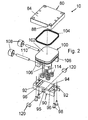
FIG. 2 shows an exploded perspective view of the linear motion brake ofFIG. 1 . -
FIG. 3 shows a cross sectional view of the linear motion brake ofFIG. 1 according to section tine 3-3 ofFIG. 1 . -
FIG. 4 shows perspective view of the integral component of the piston of the linear motion brake ofFIG. 1 . -
FIG. 5 shows a crass-sectional view of an alternate embodiment of a linear motion brake according to the present invention. - All figures are drawn for ease of explanation of the basic teachings of the present invention only; the extensions of the figures with respect to number, position, relationship, and dimensions of the parts to form the preferred embodiments will be explained or will be within the skill of the art after the following description has been read and understood.
Further, the exact dimensions and dimensional proportions to conform to specific force, weight, strength, and similar requirements will likewise be within the skill of the art after the following description has been read and understood. - Where used in the various figures of the drawings, the same numerals designate the same or similar parts. Furthermore, when the terms "first", "seconde", "inside", "outsize", "supper", "lower", "height", "width", "length", "and", "side", "horizontal", "vertical", and similar terms are used herein, it should be understood that these terms have reference only to the structure shown in the drawings as it would appear to a person viewing the drawings and are utilized only to facilitate describing the illustrative embodiments.
- A brake for stopping linearly moving loads according to the present invention is shown in the drawings and generally designated 10. Brake 10 in its most preferred form is used with a linear motion device such as a linear stage or motor which can be of any conventional design- Generally, linear motion device includes a
base plate 14 and asliding plate 16 mounted for linear motion for a distance relative to thebase plate 14 such as by two or morelinear bearings 18 slideable uponlinear races 20 in a linear movement direction. Sliding plate 15 is driven relative to thebase plate 14 such as by an armature secured to slidingplate 16 which slides through a stationary stator secured to thebase plate 14. It should be appreciated that the linear motion device can have a variety of configurations. Additionally, although having particular application to linear motion devices and believed to produce synergistic results therewith,brake 10 may have application to other drives for providing linear motion including but not limited to ball screws, belt drives, air cylinders, and the like. -
Brake 10 generally includes abrake housing 80 secured to slidingplate 16 such as bybolts 82 extending throughsliding plate 16 and threaded intohousing 80. Thus,housing 80 is mounted for movement alongrace 20 in the operation direction. In the most preferred form,housing 80 is in the form of a plate having anupper abutment surface 84 of a square, planar shape for abutment withsliding plate 16.Housing 80 includes a lower surface also of a square, planar shape parallel to and spaced fromsurface 84, with the lower surface including apiston cavity 86 extending therefrom towards but spaced fromsurface 84. Aninlet 88 extends from one of the edges ofhousing 80 and is in fluid communication withcavity 86. In the most preferred form,cavity 86 has generally square cross-sections parallel tosurface 84 andsliding plate 16, with the corners of the square cross-sections being rounded to allow fabrication. - Brake 10 further includes a
shoe guide 90 fixedly connected and secured tohousing 80. In the form shown,guide 90 is in the form of a channel and has generally U-shaped cross-sections. Specifically,guide 90 includes first andsecond leg plates 92 extending from opposite sides of a connectingplate 94.Leg plates 92 are parallel to each other and spaced a distance for receivingrace 20 without abutment.Shoe bores 95 are formed in eachleg plate 92 spaced from and extending parallel to connectingplate 94. Connectingplate 94 includes first and second rectangular cut-outs 96 extending betweenleg plates 92 and located on opposite sides ofshoe bores 96. In the preferred form,shoe guide 90 is secured tohousing 80 bybolts 98 extending through connectingplate 94 and threadably received inhousing 80 outwardly ofpiston cavity 86. To avoid interference, the heads ofbolts 98 can be countersunk in the lower surface of connectingplate 94. -
Brake 10 further includes apiston 100 reciprocally received inpiston cavity 86 for reciprocal movement in a reciprocation direction perpendicular to the operation direction. Generally,piston 100 includes ahead 102 having an outer periphery having cross-sections perpendicular to the operation direction corresponding to and for slideable receipt inpiston cavity 86.Suitable sealing 104 is provided between the outer periphery ofhead 102 andpiston cavity 86 such as a quad ring seal as shown. Piston 100 is reciprocal between a first operative position and a second operative position outwardly ofpiston cavity 86 in the reciprocation direction. In the most preferred form,piston 100 has generally U-sHaped cross-sections perpendicular to the operative direction tostraddle race 20. Particularly, first andsecond protrusions 106 extend fromhead 102 in a parallel relationship and spaced a distance for receivingshoe guide 90 parallel to and without abutment withleg plates 92. In a first preferred form, eachprotrusion 106 is in the form of a yoke for supporting acam follower 108 which in the most preferred form is in the form of a roller rotatable about an axis defined by apin 110 extending throughprotrusions 106 parallel to and spaced fromleg plates 92. - Piston 100 is biased from the second operative position towards the first operative position into
piston cavity 86. Specifically, in the most preferred form,head 102 includes a multiplicity ofspring cavities 112.Compression coil springs 114 partially located incavities 112 are sandwiched betweenhead 102 and connectingplate 94. In the most preferred form,piston 100 further includes first andsecond ribs 116 extending in a spaced, parallel relation betweenprotrusions 106 and on opposite sides ofspring cavities 112.Ribs 116 are provided for multiple purposes. Specifically,ribs 116 are slideably received incutouts 96 ofshoe guide 90 to maintainpiston 100 in position relative to theshoe guide 90 andhousing 80 to counteract the counter-forces placed thereon. Further, the presences ofribs 116 allows the thickness ofhead 102 to be minimized while still maintaining structural integrity to preventprotrusions 106 from separating due to counter-forces placed thereon. - Brake 10 further includes
brake shoes 120 of a size and shape slideably received inshoe bores 96 ofshoe guide 90 and for movement in a shoe direction defined byshoe bores 96 and perpendicular to the operative direction, to the reciprocal direction and to race 20. In particular, eachshoe 120 includes an inner interface surface 122 for interfacing withrace 20. Further, eachshoe 120 includes anouter cam surface 124 for engagement bycam follower 108. In the most preferred form shown,cam surface 124 includes a firstplanar portion 126 at an angle in the order of 20° from the reciprocation direction ofpiston 100.Cam surface 124 includes a secondplanar portion 128 at an angle in the order of 160° from firstplanar portion 126 and 5° from the reciprocation direction ofpiston 100. Secondplanar portion 128 is located intermediate firstplanar portion 126 andhead 102 ofpiston 100. - Now that the basic construction of
brake 10 has been explained, a method of operation and some advantages ofbrake 10 can be set forth. Specifically, in normal operation of the linear motion devices and specifically in other than power outage, emergency stop, parking and similar situations, fluid pressure is provided to the fluid chamber defined bypiston cavity 86 andhead 102 with sufficient pressure to movepiston 100 from the first operative position to the second operative position and out ofpiston cavity 86 and away from slidingplate 16 and against the bias ofsprings 114. Thus,cam followers 108 move downwardly relative tobrake shoes 120 and are positioned adjacent to firstplanar portion 126. In such a position,brake shoes 120 are not under compressive forces or sandwiched betweencam follower 108 andrace 20 such thatbrake shoes 120 do notgrip race 20 and thus permits relative movement ofshoe guide 90 andhousing 80 relative torace 20. Althoughshoes 120 may drag or otherwise engage withrace 20 in the disengaged position, any operational detriment is offset by the reduction in the number of components and ease of assembly and the operational and constructional advantages obtained thereby. - In the event that fluid pressure is insufficient to offset the biasing force provided by
springs 114 in the most preferred form,springs 114 will pushpiston 100 further intopiston cavity 86 and thus can followers 108 move upwardly relative tobrake shoes 120 and roll upon and are positioned on secondplanar portion 128. In such a position,brake shoes 120 arc under compression forces and are sandwiched betweencam follower 108 andrace 20 such thatbrake shoes 120 will griprace 20 and thus prevent relative movement ofshoe guide 90 andhousing 80 relative torace 20. It should be appreciated that the angle of second planar portion,128 to the reciprocation direction ofpiston 100 provides a wedging affect to enhance the braking bybrake 10. - It should be appreciated that the braking force is directly related to the biasing force which is supplied by
springs 114 in the preferred form. Furthermore, the biasing force ofsprings 114 is limited by the reverse force supplied bypiston 100 which is a function of fluid pressure and the area ofhead 102 against which fluid pressure acts. As fluid pressure available is typically from conventional sources,brake 10 is advantageous in allowing the area ofhead 102 to be maximized. Specifically, in a first aspect, the cross-sections ofhead 102 andpiston cavity 86 are generally square rather than circular of conventional piston/cylinder arrangements. Such a square cross-section increases the area ofhead 102 over a cylindrical piston having a diameter equal to the length along a side of the square cross-section furthermore, in a further aspect, the reciprocation direction is perpendicular to race 20 and to the movement direction ofbrake 10. Conventional linear brakes utilize pistons having reciprocation directions parallel to race 20 and to the movement direction ofbrake 10 and utilize placement besiderace 20.Diston cavity 86 andpiston head 102 are located aboverace 20 and thus can have a pancake type construction to maximize the area ofhead 102 against winch fluid pressure acts. Thus, the reverse force supplied bypiston 100 can be significantly increased over conventional linear motor brakes. -
Brake 10 is formed from relatively few components which are easily manufactured and assembled. Specifically, the components ofbrake 10 which cannot be purchased off the shelf can be easily machined from extruded or conventional stock such as but not limited to channel stock to formshoe guide 90 and plate stock to formhousing 80. Likewise, assembly can be quickly performed without requiring extraordinary skill, tools, jigs, or the like. -
Brake 10 does not utilize pivotal calipers which releasably griplinear race 20 and which could result in uneven wear or other detraction in the efficiency of the linear bearings andrace 20.Brake 10 applies all braking force as a result of movement ofprotrusions 106 solely in the reciprocation directly resulting in movement ofbrake shoes 120 solely in the shoe direction. Additionally, asrace 20 is sandwiched between a pair ofbrake shoes 120 inbrake 10 in the preferred form of the present invention, side loading of the linear bearing andrace 20 is minimized especially in comparison to if a single friction facing was engaged. - Many extensions and variations will be obvious to one having ordinary skill in the art. As an example, although
cam followers 108 of the preferred form are shown as mounted topiston 100 for movement relating tocamming surface 124 formed onbrake shoes 120 which is believed to produce synergistic results including, but not limited to, reduced wear on components, other manners for reciprocatingbrake shoes 120 as the result of reciprocation ofpiston 100 can be utilized. As an example, as shown inFigure 5 , thecam follower 108 could be incorporated into brake shoes 130 which are shown in the preferred form as balls. Camming surfaces 132 are formed on protrusions 134 (replacing protrusions 106) and engage with brake shoes 130, with thecamming surface 132 having greater spacing fromrace 20 with downward reciprocation ofpiston 100 by fluid pressure. - Further, although
brake 10 in the most preferred form has special application for stopping "linear motion of a linear motion device,brake 10 and/or features thereof would produce beneficial results to other applications for controlling motion including but not limited to controlling rotational motion. - Additionally, although
brake 10 of the most preferred form includes the combination of several, unique features believed to obtain synergistic result,brakes 10 could be constructed including such features single or in other combinations. As an example, brake 10 could be constructed withpiston cavity 86 andpiston head 102 of a different oross-section than as shown and described in the preferred form.
Claims (14)
- Linear motion brake (10) for a race (20) including a housing (80) adapted to be mounted for movement along the race (20) in an operation direction, with the housing (80) including a piston cavity (86), a piston (100) reciprocally received in the piston cavity (86) for reciprocal movement in a reciprocation direction perpendicular to the operation direction between a first operative position and a second operative position outwardly of the piston cavity (86) in the reciprocation direction, with the piston (100) being biased from the second operative position to the first operative position, with fluid pressure being introducible into the piston cavity (86) against the piston (100) for moving the piston (100) from the first operative position to the second operative position, first and second brake shoes (120) mounted for movement in a shoe direction perpendicular to the operation direction and to the reciprocation direction, with one of the piston (100) and the first and second brake shoes (120) including first and second camming surfaces and the other of the piston (100) and the first and second brake shoes (120) including first and second cam followers engaging with the first and second camming surfaces causing movement of the brake shoes (120) in the shoe direction when the piston (100) reciprocates in the reciprocation direction, characterized in a shoe guide (90) of a generally channel shape and secured to the housing (80), with the shoe guide (90) including first and second leg plates (92) and a connecting plate (94) extending between the first and second leg plates (92), with the first and second leg plates (92) including shoe bores (95) extending in the shoe direction through the first and second leg plates (92) for receiving the first and second brake shoes (120), with the piston (100) being biased away from the connecting plate (94) and with the piston (100) being moved under fluid pressure towards the connecting plate (94).
- The linear motion brake of claim 1 wherein the housing (80) is in the form of a plate having an abutment, upper surface (84) and an opposing lower surface, with the piston cavity (86) extending from the lower surface towards but spaced from the upper surface, with the lower surface abutting with the connecting plate (94) of the shoe guide (90).
- The linear motion brake of claim 2 with the upper and lower surfaces each being of a square, planar shape, with the lower surface being parallel to but spaced from the upper surface (84), and with the abutment, upper surface (84) including threaded openings for receiving bolts (82) for attaching a sliding plate (16).
- The linear motion brake of any proceeding claim wherein the connecting plate (94) of the shoe guide (90) includes first and second cutouts (96) extending between the first and second leg plates (92) and on opposite sides of the shoe bores (95), with the piston (100) including first and second ribs (116) slideably received in the first and second cutouts (96) of the shoe guide (90) for limiting movement of the piston (100) to the reciprocation direction.
- The linear motion brake of any proceeding claim further comprising a plurality of springs (114) extending between the shoe guide (90) and the piston (100) for biasing the piston (100) from the second operative position to the first operative position, with the piston (100) including a plurality of spring cavities (112) for receiving the plurality of springs (114).
- The linear motion brake of any proceeding claim wherein the piston (100) has a generally U-shaped cross-sections perpendicular to the operation direction and includes a piston head (102) and first and second protrusions (106, 134) extending generally perpendicular from the piston head (102) in the reciprocation direction and on opposite sides of the race (20).
- The linear motion brake of claim 6 wherein the piston head (102) and first and second protrusions (106, 134) are integrally formed as a single, unseparable component.
- The linear motion brake of claim 6 or 7 wherein the first and second protrusions (106, 134) are each in the form of yokes, with the cam followers (108) comprising a roller rotatably mounted in the yoke, with the brake shoes (120) each comprising an interface surface for engaging with the race (20) and the cam surface opposite to the interface surface in the shoe direction for engaging with the roller (108).
- The linear motion brake of claim 8 wherein the cam surface comprises a first planar portion (126) at an angle in the order of 20° from the reciprocation direction and a second planar portion (128) extending from the first planar portion at an angle in the order of 5°.
- The linear motion brake of claim 6 or 7 wherein the first and second protrusions (134) include the cam surfaces (132), with the brake shoes (120) defining the cam followers.
- The linear motion brake of claim 10 wherein each of the first and second brake shoes (120) is in the shape of a ball received in the shoe bores (95).
- The linear motion brake of any proceeding claim wherein cross-sections of the piston cavity (86) and piston (100) perpendicular to the reciprocation direction are parallel to a plane extending parallel to the operation direction and to the shoe direction.
- The linear motion brake of claim 12 wherein the cross-sections of the piston cavity (86) and the piston (100) are generally square to maximize fluid pressure operative area.
- The linear motion brake of any proceeding claim further comprising a quad ring seal mounted to the piston (100) and slideable in the piston cavity (86).
Applications Claiming Priority (2)
| Application Number | Priority Date | Filing Date | Title |
|---|---|---|---|
| US86327406P | 2006-10-27 | 2006-10-27 | |
| PCT/US2007/082664 WO2008055066A2 (en) | 2006-10-27 | 2007-10-26 | Motion control apparatus |
Publications (2)
| Publication Number | Publication Date |
|---|---|
| EP2086716A2 EP2086716A2 (en) | 2009-08-12 |
| EP2086716B1 true EP2086716B1 (en) | 2011-09-21 |
Family
ID=39267903
Family Applications (1)
| Application Number | Title | Priority Date | Filing Date |
|---|---|---|---|
| EP07844642A Not-in-force EP2086716B1 (en) | 2006-10-27 | 2007-10-26 | Motion control apparatus |
Country Status (9)
| Country | Link |
|---|---|
| US (1) | US8220592B2 (en) |
| EP (1) | EP2086716B1 (en) |
| JP (1) | JP4975107B2 (en) |
| KR (1) | KR101432217B1 (en) |
| CN (1) | CN101583460B (en) |
| AT (1) | ATE525164T1 (en) |
| CA (1) | CA2667632C (en) |
| MX (1) | MX2009004357A (en) |
| WO (1) | WO2008055066A2 (en) |
Families Citing this family (14)
| Publication number | Priority date | Publication date | Assignee | Title |
|---|---|---|---|---|
| DE102008027529A1 (en) * | 2008-06-10 | 2009-12-17 | Frenotech Establishment | admission |
| JP5758773B2 (en) * | 2011-10-24 | 2015-08-05 | 旭精工株式会社 | Linear brake |
| DE102012025438A1 (en) | 2012-12-21 | 2014-06-26 | Chr. Mayr Gmbh + Co. Kg | By means of external energy actuated linear brake |
| CN103029002B (en) * | 2012-12-27 | 2016-01-06 | 威海华东重工有限公司 | Hydraulic rolling composite guide rails relief arrangement |
| FI20135294A7 (en) | 2013-03-26 | 2014-09-27 | Kone Corp | Brake and elevator system |
| CN105619150B (en) * | 2014-10-28 | 2018-03-13 | 富鼎电子科技(嘉善)有限公司 | Arrestment mechanism and the processing unit (plant) using the arrestment mechanism |
| CN105537975B (en) * | 2014-10-28 | 2017-08-25 | 富鼎电子科技(嘉善)有限公司 | Sliding equipment and the processing unit (plant) using the sliding equipment |
| JP6615664B2 (en) * | 2016-03-22 | 2019-12-04 | 鍋屋バイテック株式会社 | Linear brake support method, linear brake assembly and linear brake adapter |
| CN106917835A (en) * | 2017-04-25 | 2017-07-04 | 济南派克机器有限公司 | Guide rail Sha Jin mechanisms |
| TWI665049B (en) * | 2017-12-08 | 2019-07-11 | 高聖精密機電股份有限公司 | Track displacement mechanism with braking device |
| CN111043194B (en) * | 2018-08-23 | 2021-05-25 | 南通昆锻机械科技有限公司 | Unpowered pneumatic brake and braking method |
| DE102020002649A1 (en) | 2020-05-02 | 2021-11-04 | Chr. Mayr Gmbh + Co. Kg | Pressure fluid operated linear brake and tuning process |
| DE102020120313B4 (en) * | 2020-07-31 | 2022-06-09 | Ringspann Gmbh | caliper brake |
| TWI737436B (en) * | 2020-08-06 | 2021-08-21 | 上銀科技股份有限公司 | Clamped slider for linear slides |
Family Cites Families (24)
| Publication number | Priority date | Publication date | Assignee | Title |
|---|---|---|---|---|
| DE6907934U (en) * | 1969-03-04 | 1969-06-19 | Hurth Masch Zahnrad Carl | DEVICE FOR CLAMPING MOVABLE SUPPORT PLATES ON MACHINE TOOLS |
| DE3514074A1 (en) | 1985-04-18 | 1986-10-23 | Herion-Werke Kg, 7012 Fellbach | Rodless cylinder |
| JPH0729282Y2 (en) * | 1988-07-13 | 1995-07-05 | エスエムシー株式会社 | Rocking cylinder |
| DE69100636T2 (en) * | 1990-02-09 | 1994-05-26 | Bo Kungsoer Granbom | Braking device in a straight-line movement device. |
| DE4012524A1 (en) * | 1990-04-19 | 1991-10-24 | Doma Tech Pneumatische Kompone | LOCKING DEVICE FOR A LINEAR MOTION UNIT |
| EP0747602A3 (en) * | 1992-01-23 | 1998-02-25 | Smc Corporation | Rodless cylinder unit with brake |
| JP3308666B2 (en) * | 1993-08-10 | 2002-07-29 | ヤマザキマザック株式会社 | Linear motion guide device |
| JPH08121476A (en) * | 1994-10-27 | 1996-05-14 | Nippon Thompson Co Ltd | Suppression device and rolling guide unit equipped with the same |
| DE19715014A1 (en) * | 1997-04-11 | 1998-10-15 | Schaeffler Waelzlager Ohg | Linear guide |
| JPH1137111A (en) * | 1997-07-14 | 1999-02-09 | Shigeyuki Yano | Stopping device for straight cylinder |
| ATE281905T1 (en) | 1999-06-07 | 2004-11-15 | Frenotech Establishment | LOCKING DEVICE FOR CLAMPING A SHAFT OR ROD |
| US6460678B1 (en) * | 2000-10-24 | 2002-10-08 | Nexen Group, Inc. | Linear motion brake |
| JP2003148463A (en) * | 2001-11-12 | 2003-05-21 | Pubot Giken:Kk | Linear motion lock device |
| US6578677B2 (en) * | 2001-11-21 | 2003-06-17 | Industrial Technology Research Institute | Braking device of linear guide |
| DE20202803U1 (en) | 2002-02-22 | 2003-07-03 | Zimmer Gmbh Tech Werkstaetten | Compact hydraulic brake for rail mounted system has a triple piston braking cylinder operating against a braking spring |
| DE10225353A1 (en) | 2002-06-07 | 2003-12-18 | Kendrion Binder Magnete Gmbh | Electromagnetically liftable brake has a coil and armature to lift against a spring whose force depends on a tapering in the brake body |
| JP2005529757A (en) * | 2002-06-12 | 2005-10-06 | ユニスト,インコーポレイテッド | Coaxial lubrication system |
| DE10252915B3 (en) * | 2002-11-12 | 2004-04-08 | Zimmer GmbH, Technische Werkstätten | Friction clamp with emergency brake function for objects sliding on a rail, such as motor vehicle jacks and sealant cartridges, has spring clamping and pneumatic releasing assistance |
| US7124861B2 (en) * | 2004-02-20 | 2006-10-24 | Nexen Group, Inc. | Motion control apparatus |
| DE202004019930U1 (en) | 2004-12-18 | 2005-02-24 | Wunderwald, Manfred, Dr. | Arrangement for linear moving of attached elements, to be arrested by forces acting on locking unit |
| JP4587103B2 (en) * | 2005-04-19 | 2010-11-24 | Smc株式会社 | Cylinder device guide mechanism |
| DE102006008403A1 (en) * | 2006-02-21 | 2007-08-30 | Klaus Hofmann | Clamping and/or braking device e.g. pneumatically actuatable clamping and/or braking device, has actuating unit configured as pin or spike and acting upon hydraulic medium through aperture in wall of housing |
| US8210323B2 (en) * | 2007-04-16 | 2012-07-03 | Nexen Group, Inc. | Motion control apparatus |
| DE102009008815B4 (en) * | 2009-02-13 | 2011-04-28 | Zimmer, Günther | Friction crutch with transverse cage |
-
2007
- 2007-10-26 EP EP07844642A patent/EP2086716B1/en not_active Not-in-force
- 2007-10-26 CN CN2007800466917A patent/CN101583460B/en not_active Expired - Fee Related
- 2007-10-26 MX MX2009004357A patent/MX2009004357A/en active IP Right Grant
- 2007-10-26 WO PCT/US2007/082664 patent/WO2008055066A2/en not_active Ceased
- 2007-10-26 AT AT07844642T patent/ATE525164T1/en not_active IP Right Cessation
- 2007-10-26 JP JP2009534888A patent/JP4975107B2/en not_active Expired - Fee Related
- 2007-10-26 CA CA2667632A patent/CA2667632C/en not_active Expired - Fee Related
- 2007-10-26 US US12/447,284 patent/US8220592B2/en active Active
- 2007-10-26 KR KR1020097010858A patent/KR101432217B1/en not_active Expired - Fee Related
Also Published As
| Publication number | Publication date |
|---|---|
| KR101432217B1 (en) | 2014-08-26 |
| US8220592B2 (en) | 2012-07-17 |
| US20100065383A1 (en) | 2010-03-18 |
| CA2667632C (en) | 2014-12-30 |
| CA2667632A1 (en) | 2008-05-08 |
| CN101583460B (en) | 2011-10-05 |
| MX2009004357A (en) | 2009-07-22 |
| CN101583460A (en) | 2009-11-18 |
| JP2010508477A (en) | 2010-03-18 |
| WO2008055066A2 (en) | 2008-05-08 |
| EP2086716A2 (en) | 2009-08-12 |
| ATE525164T1 (en) | 2011-10-15 |
| WO2008055066A3 (en) | 2008-06-19 |
| KR20090077969A (en) | 2009-07-16 |
| JP4975107B2 (en) | 2012-07-11 |
Similar Documents
| Publication | Publication Date | Title |
|---|---|---|
| US8220592B2 (en) | Motion control apparatus | |
| US9316262B2 (en) | Linear brake operated by means of external energy | |
| CA2556924C (en) | Motion control apparatus | |
| US6135029A (en) | Linear motion brake | |
| US7431503B2 (en) | Bearing support structure for actuator | |
| CN204878110U (en) | A slide cylinder | |
| CN217950879U (en) | Cylinder brake structure | |
| CN221559549U (en) | Upper bending die assembly of bending machine and bending machine | |
| CN224209056U (en) | Hydraulic locking mechanism of die holder | |
| KR100340342B1 (en) | Slide cylinder | |
| JP3557074B2 (en) | Multistage compression device | |
| CN220396325U (en) | Auxiliary brake mechanism of multi-station woodworking drilling and milling processing equipment | |
| CN114734672B (en) | Stamping equipment | |
| CN220363038U (en) | Brake structure for chain sheet punching machine | |
| CN219529449U (en) | Hydraulic cylinder with buffering function | |
| KR200188486Y1 (en) | Slide cylinder | |
| JP2005016622A (en) | Stopper member for linear motion device | |
| JPWO1992008057A1 (en) | Cylinder brake device | |
| JPH0716005U (en) | Brake device for cable cylinder | |
| KR20040083625A (en) | Linear actuator using a slide bearing |
Legal Events
| Date | Code | Title | Description |
|---|---|---|---|
| PUAI | Public reference made under article 153(3) epc to a published international application that has entered the european phase |
Free format text: ORIGINAL CODE: 0009012 |
|
| 17P | Request for examination filed |
Effective date: 20090527 |
|
| AK | Designated contracting states |
Kind code of ref document: A2 Designated state(s): AT BE BG CH CY CZ DE DK EE ES FI FR GB GR HU IE IS IT LI LT LU LV MC MT NL PL PT RO SE SI SK TR |
|
| DAX | Request for extension of the european patent (deleted) | ||
| 17Q | First examination report despatched |
Effective date: 20100304 |
|
| GRAP | Despatch of communication of intention to grant a patent |
Free format text: ORIGINAL CODE: EPIDOSNIGR1 |
|
| GRAS | Grant fee paid |
Free format text: ORIGINAL CODE: EPIDOSNIGR3 |
|
| GRAA | (expected) grant |
Free format text: ORIGINAL CODE: 0009210 |
|
| AK | Designated contracting states |
Kind code of ref document: B1 Designated state(s): AT BE BG CH CY CZ DE DK EE ES FI FR GB GR HU IE IS IT LI LT LU LV MC MT NL PL PT RO SE SI SK TR |
|
| REG | Reference to a national code |
Ref country code: GB Ref legal event code: FG4D |
|
| REG | Reference to a national code |
Ref country code: CH Ref legal event code: EP |
|
| REG | Reference to a national code |
Ref country code: IE Ref legal event code: FG4D |
|
| REG | Reference to a national code |
Ref country code: DE Ref legal event code: R096 Ref document number: 602007017419 Country of ref document: DE Effective date: 20111201 |
|
| REG | Reference to a national code |
Ref country code: NL Ref legal event code: VDEP Effective date: 20110921 |
|
| PG25 | Lapsed in a contracting state [announced via postgrant information from national office to epo] |
Ref country code: FI Free format text: LAPSE BECAUSE OF FAILURE TO SUBMIT A TRANSLATION OF THE DESCRIPTION OR TO PAY THE FEE WITHIN THE PRESCRIBED TIME-LIMIT Effective date: 20110921 Ref country code: SE Free format text: LAPSE BECAUSE OF FAILURE TO SUBMIT A TRANSLATION OF THE DESCRIPTION OR TO PAY THE FEE WITHIN THE PRESCRIBED TIME-LIMIT Effective date: 20110921 Ref country code: LT Free format text: LAPSE BECAUSE OF FAILURE TO SUBMIT A TRANSLATION OF THE DESCRIPTION OR TO PAY THE FEE WITHIN THE PRESCRIBED TIME-LIMIT Effective date: 20110921 |
|
| LTIE | Lt: invalidation of european patent or patent extension |
Effective date: 20110921 |
|
| PG25 | Lapsed in a contracting state [announced via postgrant information from national office to epo] |
Ref country code: GR Free format text: LAPSE BECAUSE OF FAILURE TO SUBMIT A TRANSLATION OF THE DESCRIPTION OR TO PAY THE FEE WITHIN THE PRESCRIBED TIME-LIMIT Effective date: 20111222 Ref country code: AT Free format text: LAPSE BECAUSE OF FAILURE TO SUBMIT A TRANSLATION OF THE DESCRIPTION OR TO PAY THE FEE WITHIN THE PRESCRIBED TIME-LIMIT Effective date: 20110921 Ref country code: LV Free format text: LAPSE BECAUSE OF FAILURE TO SUBMIT A TRANSLATION OF THE DESCRIPTION OR TO PAY THE FEE WITHIN THE PRESCRIBED TIME-LIMIT Effective date: 20110921 Ref country code: CY Free format text: LAPSE BECAUSE OF FAILURE TO SUBMIT A TRANSLATION OF THE DESCRIPTION OR TO PAY THE FEE WITHIN THE PRESCRIBED TIME-LIMIT Effective date: 20110921 Ref country code: SI Free format text: LAPSE BECAUSE OF FAILURE TO SUBMIT A TRANSLATION OF THE DESCRIPTION OR TO PAY THE FEE WITHIN THE PRESCRIBED TIME-LIMIT Effective date: 20110921 |
|
| REG | Reference to a national code |
Ref country code: AT Ref legal event code: MK05 Ref document number: 525164 Country of ref document: AT Kind code of ref document: T Effective date: 20110921 |
|
| PG25 | Lapsed in a contracting state [announced via postgrant information from national office to epo] |
Ref country code: BE Free format text: LAPSE BECAUSE OF FAILURE TO SUBMIT A TRANSLATION OF THE DESCRIPTION OR TO PAY THE FEE WITHIN THE PRESCRIBED TIME-LIMIT Effective date: 20110921 |
|
| PG25 | Lapsed in a contracting state [announced via postgrant information from national office to epo] |
Ref country code: CZ Free format text: LAPSE BECAUSE OF FAILURE TO SUBMIT A TRANSLATION OF THE DESCRIPTION OR TO PAY THE FEE WITHIN THE PRESCRIBED TIME-LIMIT Effective date: 20110921 Ref country code: IS Free format text: LAPSE BECAUSE OF FAILURE TO SUBMIT A TRANSLATION OF THE DESCRIPTION OR TO PAY THE FEE WITHIN THE PRESCRIBED TIME-LIMIT Effective date: 20120121 Ref country code: SK Free format text: LAPSE BECAUSE OF FAILURE TO SUBMIT A TRANSLATION OF THE DESCRIPTION OR TO PAY THE FEE WITHIN THE PRESCRIBED TIME-LIMIT Effective date: 20110921 |
|
| PG25 | Lapsed in a contracting state [announced via postgrant information from national office to epo] |
Ref country code: RO Free format text: LAPSE BECAUSE OF FAILURE TO SUBMIT A TRANSLATION OF THE DESCRIPTION OR TO PAY THE FEE WITHIN THE PRESCRIBED TIME-LIMIT Effective date: 20110921 Ref country code: PL Free format text: LAPSE BECAUSE OF FAILURE TO SUBMIT A TRANSLATION OF THE DESCRIPTION OR TO PAY THE FEE WITHIN THE PRESCRIBED TIME-LIMIT Effective date: 20110921 Ref country code: PT Free format text: LAPSE BECAUSE OF FAILURE TO SUBMIT A TRANSLATION OF THE DESCRIPTION OR TO PAY THE FEE WITHIN THE PRESCRIBED TIME-LIMIT Effective date: 20120123 Ref country code: NL Free format text: LAPSE BECAUSE OF FAILURE TO SUBMIT A TRANSLATION OF THE DESCRIPTION OR TO PAY THE FEE WITHIN THE PRESCRIBED TIME-LIMIT Effective date: 20110921 Ref country code: EE Free format text: LAPSE BECAUSE OF FAILURE TO SUBMIT A TRANSLATION OF THE DESCRIPTION OR TO PAY THE FEE WITHIN THE PRESCRIBED TIME-LIMIT Effective date: 20110921 Ref country code: MC Free format text: LAPSE BECAUSE OF NON-PAYMENT OF DUE FEES Effective date: 20111031 |
|
| REG | Reference to a national code |
Ref country code: CH Ref legal event code: PL |
|
| PLBE | No opposition filed within time limit |
Free format text: ORIGINAL CODE: 0009261 |
|
| STAA | Information on the status of an ep patent application or granted ep patent |
Free format text: STATUS: NO OPPOSITION FILED WITHIN TIME LIMIT |
|
| PG25 | Lapsed in a contracting state [announced via postgrant information from national office to epo] |
Ref country code: LI Free format text: LAPSE BECAUSE OF NON-PAYMENT OF DUE FEES Effective date: 20111031 Ref country code: CH Free format text: LAPSE BECAUSE OF NON-PAYMENT OF DUE FEES Effective date: 20111031 Ref country code: DK Free format text: LAPSE BECAUSE OF FAILURE TO SUBMIT A TRANSLATION OF THE DESCRIPTION OR TO PAY THE FEE WITHIN THE PRESCRIBED TIME-LIMIT Effective date: 20110921 |
|
| REG | Reference to a national code |
Ref country code: IE Ref legal event code: MM4A |
|
| 26N | No opposition filed |
Effective date: 20120622 |
|
| REG | Reference to a national code |
Ref country code: DE Ref legal event code: R097 Ref document number: 602007017419 Country of ref document: DE Effective date: 20120622 |
|
| PG25 | Lapsed in a contracting state [announced via postgrant information from national office to epo] |
Ref country code: IE Free format text: LAPSE BECAUSE OF NON-PAYMENT OF DUE FEES Effective date: 20111026 |
|
| PG25 | Lapsed in a contracting state [announced via postgrant information from national office to epo] |
Ref country code: MT Free format text: LAPSE BECAUSE OF FAILURE TO SUBMIT A TRANSLATION OF THE DESCRIPTION OR TO PAY THE FEE WITHIN THE PRESCRIBED TIME-LIMIT Effective date: 20110921 |
|
| PG25 | Lapsed in a contracting state [announced via postgrant information from national office to epo] |
Ref country code: ES Free format text: LAPSE BECAUSE OF FAILURE TO SUBMIT A TRANSLATION OF THE DESCRIPTION OR TO PAY THE FEE WITHIN THE PRESCRIBED TIME-LIMIT Effective date: 20120101 |
|
| PG25 | Lapsed in a contracting state [announced via postgrant information from national office to epo] |
Ref country code: LU Free format text: LAPSE BECAUSE OF NON-PAYMENT OF DUE FEES Effective date: 20111026 |
|
| PG25 | Lapsed in a contracting state [announced via postgrant information from national office to epo] |
Ref country code: BG Free format text: LAPSE BECAUSE OF FAILURE TO SUBMIT A TRANSLATION OF THE DESCRIPTION OR TO PAY THE FEE WITHIN THE PRESCRIBED TIME-LIMIT Effective date: 20111221 |
|
| PG25 | Lapsed in a contracting state [announced via postgrant information from national office to epo] |
Ref country code: TR Free format text: LAPSE BECAUSE OF FAILURE TO SUBMIT A TRANSLATION OF THE DESCRIPTION OR TO PAY THE FEE WITHIN THE PRESCRIBED TIME-LIMIT Effective date: 20110921 |
|
| PG25 | Lapsed in a contracting state [announced via postgrant information from national office to epo] |
Ref country code: HU Free format text: LAPSE BECAUSE OF FAILURE TO SUBMIT A TRANSLATION OF THE DESCRIPTION OR TO PAY THE FEE WITHIN THE PRESCRIBED TIME-LIMIT Effective date: 20110921 |
|
| REG | Reference to a national code |
Ref country code: FR Ref legal event code: PLFP Year of fee payment: 9 |
|
| REG | Reference to a national code |
Ref country code: FR Ref legal event code: PLFP Year of fee payment: 10 |
|
| REG | Reference to a national code |
Ref country code: FR Ref legal event code: PLFP Year of fee payment: 11 |
|
| PGFP | Annual fee paid to national office [announced via postgrant information from national office to epo] |
Ref country code: FR Payment date: 20171024 Year of fee payment: 11 Ref country code: DE Payment date: 20171019 Year of fee payment: 11 |
|
| PGFP | Annual fee paid to national office [announced via postgrant information from national office to epo] |
Ref country code: GB Payment date: 20171019 Year of fee payment: 11 Ref country code: IT Payment date: 20171025 Year of fee payment: 11 |
|
| REG | Reference to a national code |
Ref country code: DE Ref legal event code: R119 Ref document number: 602007017419 Country of ref document: DE |
|
| GBPC | Gb: european patent ceased through non-payment of renewal fee |
Effective date: 20181026 |
|
| PG25 | Lapsed in a contracting state [announced via postgrant information from national office to epo] |
Ref country code: DE Free format text: LAPSE BECAUSE OF NON-PAYMENT OF DUE FEES Effective date: 20190501 |
|
| PG25 | Lapsed in a contracting state [announced via postgrant information from national office to epo] |
Ref country code: FR Free format text: LAPSE BECAUSE OF NON-PAYMENT OF DUE FEES Effective date: 20181031 |
|
| PG25 | Lapsed in a contracting state [announced via postgrant information from national office to epo] |
Ref country code: IT Free format text: LAPSE BECAUSE OF NON-PAYMENT OF DUE FEES Effective date: 20181026 Ref country code: GB Free format text: LAPSE BECAUSE OF NON-PAYMENT OF DUE FEES Effective date: 20181026 |