EP2085819A1 - Projector - Google Patents
Projector Download PDFInfo
- Publication number
- EP2085819A1 EP2085819A1 EP07830341A EP07830341A EP2085819A1 EP 2085819 A1 EP2085819 A1 EP 2085819A1 EP 07830341 A EP07830341 A EP 07830341A EP 07830341 A EP07830341 A EP 07830341A EP 2085819 A1 EP2085819 A1 EP 2085819A1
- Authority
- EP
- European Patent Office
- Prior art keywords
- air
- liquid crystal
- main body
- evaporator
- zone
- Prior art date
- Legal status (The legal status is an assumption and is not a legal conclusion. Google has not performed a legal analysis and makes no representation as to the accuracy of the status listed.)
- Granted
Links
Images




Classifications
-
- H—ELECTRICITY
- H04—ELECTRIC COMMUNICATION TECHNIQUE
- H04N—PICTORIAL COMMUNICATION, e.g. TELEVISION
- H04N9/00—Details of colour television systems
- H04N9/12—Picture reproducers
- H04N9/31—Projection devices for colour picture display, e.g. using electronic spatial light modulators [ESLM]
- H04N9/3102—Projection devices for colour picture display, e.g. using electronic spatial light modulators [ESLM] using two-dimensional electronic spatial light modulators
- H04N9/3105—Projection devices for colour picture display, e.g. using electronic spatial light modulators [ESLM] using two-dimensional electronic spatial light modulators for displaying all colours simultaneously, e.g. by using two or more electronic spatial light modulators
-
- G—PHYSICS
- G02—OPTICS
- G02F—OPTICAL DEVICES OR ARRANGEMENTS FOR THE CONTROL OF LIGHT BY MODIFICATION OF THE OPTICAL PROPERTIES OF THE MEDIA OF THE ELEMENTS INVOLVED THEREIN; NON-LINEAR OPTICS; FREQUENCY-CHANGING OF LIGHT; OPTICAL LOGIC ELEMENTS; OPTICAL ANALOGUE/DIGITAL CONVERTERS
- G02F1/00—Devices or arrangements for the control of the intensity, colour, phase, polarisation or direction of light arriving from an independent light source, e.g. switching, gating or modulating; Non-linear optics
- G02F1/01—Devices or arrangements for the control of the intensity, colour, phase, polarisation or direction of light arriving from an independent light source, e.g. switching, gating or modulating; Non-linear optics for the control of the intensity, phase, polarisation or colour
- G02F1/13—Devices or arrangements for the control of the intensity, colour, phase, polarisation or direction of light arriving from an independent light source, e.g. switching, gating or modulating; Non-linear optics for the control of the intensity, phase, polarisation or colour based on liquid crystals, e.g. single liquid crystal display cells
- G02F1/133—Constructional arrangements; Operation of liquid crystal cells; Circuit arrangements
- G02F1/1333—Constructional arrangements; Manufacturing methods
- G02F1/133382—Heating or cooling of liquid crystal cells other than for activation, e.g. circuits or arrangements for temperature control, stabilisation or uniform distribution over the cell
- G02F1/133385—Heating or cooling of liquid crystal cells other than for activation, e.g. circuits or arrangements for temperature control, stabilisation or uniform distribution over the cell with cooling means, e.g. fans
-
- G—PHYSICS
- G03—PHOTOGRAPHY; CINEMATOGRAPHY; ANALOGOUS TECHNIQUES USING WAVES OTHER THAN OPTICAL WAVES; ELECTROGRAPHY; HOLOGRAPHY
- G03B—APPARATUS OR ARRANGEMENTS FOR TAKING PHOTOGRAPHS OR FOR PROJECTING OR VIEWING THEM; APPARATUS OR ARRANGEMENTS EMPLOYING ANALOGOUS TECHNIQUES USING WAVES OTHER THAN OPTICAL WAVES; ACCESSORIES THEREFOR
- G03B21/00—Projectors or projection-type viewers; Accessories therefor
- G03B21/14—Details
- G03B21/16—Cooling; Preventing overheating
-
- H—ELECTRICITY
- H04—ELECTRIC COMMUNICATION TECHNIQUE
- H04N—PICTORIAL COMMUNICATION, e.g. TELEVISION
- H04N9/00—Details of colour television systems
- H04N9/12—Picture reproducers
- H04N9/31—Projection devices for colour picture display, e.g. using electronic spatial light modulators [ESLM]
- H04N9/3141—Constructional details thereof
- H04N9/3144—Cooling systems
-
- H—ELECTRICITY
- H04—ELECTRIC COMMUNICATION TECHNIQUE
- H04N—PICTORIAL COMMUNICATION, e.g. TELEVISION
- H04N9/00—Details of colour television systems
- H04N9/12—Picture reproducers
- H04N9/31—Projection devices for colour picture display, e.g. using electronic spatial light modulators [ESLM]
- H04N9/3141—Constructional details thereof
- H04N9/315—Modulator illumination systems
- H04N9/3164—Modulator illumination systems using multiple light sources
Definitions
- the present invention relates to a projector which processes light emitted from a light source by an optical element to project a processed projection optical image onto a screen by a projection lens.
- a liquid crystal projector has a constitution in which a light source, a liquid crystal panel (an optical element), a projection lens and the like are mounted in a main body.
- the liquid crystal panel is constituted of three liquid crystal panels for processing (modulating) color rays in accordance with image information generally as light bulbs.
- image information generally as light bulbs.
- light emitted from the light source is split into the color rays, processed (modulated) by the liquid crystal panels in accordance with the image information and synthesized as a projection optical image through a prism and the like. Then, the synthesized projection optical image is enlarged and projected onto a screen by the projection lens.
- the light source and the optical element are heat generation sources to bring the inside of the main body into a heated state. Therefore, a plurality of fans are installed in the main body, and supply (blow) air outside the projector (the outside air) to the optical element and the light source to release the heat.
- the light source has a very high temperature of about +900°C, and the heat can sufficiently be released by the outside air, but the upper limit of the use temperature of the optical element is a comparatively low temperature.
- the upper limit of the use temperature is about +70°C to +80°C.
- the amount of the heat to be released from the optical elements is noticeably influenced by an outside air temperature. That is, when the outside air temperature is low, the optical elements can sufficiently release the heat to the supplied outside air. However, when the outside air temperature is high, the amount of the air to be blown by the fans needs to be increased to secure the amount of the heat to be released. Therefore, noise due to the operation of the fans increases, and a problem also occurs that power consumption remarkably soars.
- thermoelectric cooling to cool the liquid crystal panels (the optical elements) (e.g., see Japanese Patent Application Laid-Open No. 2005-121250 ).
- thermoelectric cooling has a poor energy efficiency, and a heat generating section for the thermoelectric cooling is integrally constituted. Therefore, means for releasing the heat to the outside air (a heat sink or the fans) is required near a cooling target, and a problem has occurred that a spatial restriction is generated to remarkably lower a degree of freedom in design.
- the present invention has been developed to solve a conventional technical problem, and an object thereof is to provide a projector capable of efficiently cooling an optical element while decreasing the generation of noise as much as possible.
- the projector of the present invention comprises a main body provided with a light source, an optical element which processes light emitted from this light source in accordance with image information and a projection lens which projects a processed projection optical image onto a screen, and further comprises a cooling apparatus in which a compressor, a radiator, a pressure reducing unit and an evaporator provided in the main body constitute a refrigerant circuit, characterized in that air subjected to heat exchange between the air and the evaporator is supplied to the optical element to cool the optical element.
- the projector of a second aspect of the invention is characterized in that in the invention of a first aspect, the inside of the main body is partitioned into a first zone in which the light source is provided and a second zone in which the optical element is provided and which is sealed, and the air subjected to the heat exchange between the air and the evaporator is circulated through this second zone.
- the projector of a third aspect of the invention is characterized in that in the invention of the first aspect or the second aspect, the inside of the main body is partitioned into the first zone and the second zone by a partition member, and this partition member is made of an insulating material.
- the projector of a fourth aspect of the invention is characterized in that in the invention of the third aspect, the partition member is constituted of a plurality of plate members, and detachably provided in the main body.
- the projector of a fifth aspect of the invention is characterized in that in the invention of the first aspect, cold air subjected to the heat exchange between the air and the evaporator is supplied to the optical element through a duct.
- the projector of a sixth aspect of the invention is characterized in that in the invention of the fifth aspect, the evaporator constitutes a part of the duct or is provided in this duct, and the duct is made of an insulating material, and constituted so that the cold air subjected to the heat exchange between the air and the evaporator is circulated through the duct.
- the projector of a seventh aspect of the invention is characterized in that in the invention of the fifth aspect or the sixth aspect, the duct is constituted of a plurality of members detachably provided in the main body.
- the projector of an eighth aspect of the invention is characterized in that in the invention according to any one of the first to seventh aspects, the optical element includes a liquid crystal panel, polarization plates provided on the incidence side and the emission side of this liquid crystal panel, and a prism.
- the projector comprises the main body provided with the light source, the optical element which processes the light emitted from this light source in accordance with the image information and the projection lens which projects the processed projection optical image onto the screen, and the projector further comprises the cooling apparatus in which the compressor, the radiator, the pressure reducing unit and the evaporator provided in the main body constitute the refrigerant circuit, and the air subjected to the heat exchange between the air and the evaporator is supplied to the optical element to cool the optical element. Therefore, the optical element can be cooled without being influenced by an outside air temperature. In consequence, the optical element can always be kept at a constant temperature.
- the cold air subjected to the heat exchange between the air and the evaporator can constantly be supplied to the optical element. Therefore, a fan can be miniaturized, the amount of air to be blown by the fan can be decreased, and hence the reduction of an installation space and the decrease of noise can be achieved. Furthermore, an energy efficiency can be improved.
- the inside of the main body is partitioned into the first zone in which the light source is provided and the second zone in which the optical element is provided and which is sealed, and the air subjected to the heat exchange between the air and the evaporator is circulated through this second zone.
- the optical element can be separated from the light source having a higher temperature, and it is possible to eliminate a disadvantage that the optical element is influenced by the heat from the light source. In consequence, a further cooling effect can be secured.
- any outside air does not enter the second zone, and the second zone constitutes a sealed space through which the air is circulated. Therefore, the whole second zone can homogeneously be cooled.
- any dust or mote does not enter the zone from the outside air, and hence any filter is not necessary, so that the improvement of the quality of the optical element and the decrease of cost can be achieved.
- the inside of the main body is partitioned into the first zone and the second zone by the partition member, and this partition member is made of the insulating material, whereby it is possible to eliminate a disadvantage that the optical element in the second zone is influenced by the heat from the light source in the second zone.
- the partition member is constituted of the plurality of plate members, and detachably provided in the main body, whereby an assembling operation during production, a removal operation during repair or the like, or an assembling operation after the repair can easily be performed.
- the cold air subjected to the heat exchange between the air and the evaporator is supplied to the optical element through the duct, whereby the cold air subjected to the heat exchange between the air and the evaporator can efficiently be supplied to the optical element, and the heat release effect of the optical element can be promoted.
- the evaporator constitutes a part of the duct or is provided in the duct, and the duct is made of the insulating material, and constituted so that the cold air subjected to the heat exchange between the air and the evaporator can be circulated through the duct.
- the cold air subjected to the heat exchange between the air and the evaporator can more effectively be supplied to the optical element, and the heat release effect of the optical element can further be promoted.
- the duct is constituted of the plurality of members detachably provided in the main body, whereby the assembling operation during the production, the removal operation during the repair or the like or the assembling operation after the repair can easily be performed.
- the removal or assembling of each device provided in the duct can easily be performed, and operability can remarkably be improved.
- the optical element includes the liquid crystal panel, the polarization plates provided on the incidence side and the emission side of this liquid crystal panel, and the prism, so that according to the first to seventh aspects of the invention, while decreasing the generation of the noise of the projector including the liquid crystal panel, the polarization plates and the prism as much as possible, the liquid crystal panel, the polarization plates and the prism can efficiently be cooled.
- the present invention relates to a projector, and an object thereof is to efficiently cool an optical element while solving a problem of noise generated in a case where outside air is supplied to the optical element by a fan to release heat, and a problem of an energy efficiency due to the cooling of the optical element by thermoelectric cooling.
- the object of efficiently cooling the optical element while decreasing the generation of the noise as much an possible is realized by disposing a cooling apparatus in which a compressor, a radiator, a pressure reducing unit and an evaporator provided in a main body constitute a refrigerant circuit and supplying air subjected to heat exchange between the air and the evaporator to the optical element to cool the optical element.
- FIG. 1 is a schematic perspective view showing a projector of one embodiment of the present invention
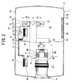
- FIG. 2 is a plan view of FIG. 1
- the projector of the embodiment is a liquid crystal projector P having a main body 1 provided with a light source 2, a homogeneous illumination optical system 3, a color splitting optical system (not shown), an optical element 4, a projection lens 9 and a cooling apparatus 10 for the optical element 4.
- the main body 1 is a flat housing made of a material excellent in heat release properties, for example, magnesium. It is to be noted that in FIGS. 1 and 2 , for the description of each device provided in the main body 1, the main body 1 is shown by a flat section of a cut upper part.
- the light source 2 includes a lamp 20 such as an extra high pressure mercury lamp, and a reflector 21 for emitting forwards light (diverging light) diverging from the lamp ( FIG. 2 ).
- the light source 2 of the embodiment has a constitution in which the reflectors 21 are attached to a plurality of (four) lamps 20, respectively, and the light source is received in a lamp box 22 provided in the main body 1.
- the homogeneous illumination optical system 3 forms the light emitted from the light source 2 into a parallel luminous flux having a homogeneous luminance distribution, and includes an integrator lens, a condensing lens, a total reflection mirror and the like.
- the color splitting optical system splits the parallel luminous flux from the homogeneous illumination optical system 3 into color rays of colors R, G and B, and includes a reflecting mirror for splitting the parallel luminous flux from the homogeneous illumination optical system 3 into the colors, a prism for guiding the split color luminous fluxes to the optical element 4 and the like.
- the optical element 4 includes three liquid crystal panels (LCD panels) 5, 6 and 7, polarization plates 8A provided on the incidence sides of the liquid crystal panels 5, 6 and 7 with spaces being left between the plates and the panels, polarization plates 8B provided on the emission sides of the liquid crystal panels 5, 6 and 7 with spaces being left between the plates and the panels, a prism 25 and the like.
- the liquid crystal panels 5, 6 and 7 process (modulate) the light split by the color splitting optical system and guided to the liquid crystal panels 5, 6 and 7 in accordance with image information.
- the prism 25 synthesizes the respective color rays to form a projection optical image.
- This prism 25 includes a reflective face constituted of an X-like dielectric multilayered film, and the light from the liquid crystal panels 5, 6 and 7 is formed into a single luminous flux through the reflective face.
- the projection lens 9 enlarges and projects the projection optical image from the prism 25 onto a screen, and is detachably arranged in a hole (not shown) formed in a wall face of the main body 1.
- reference numeral 27 is a box member which covers a light path for guiding the light emitted from the light source 2 to the liquid crystal panels 5, 6 and 7, the polarization plates 8A, 8B and the like. That is, in the box member 27, the path (the light path) is formed through which the light passes from the light source 2 to the polarization plates 8A on the incidence sides of the liquid crystal panels 5, 6 and 7.
- the light emitted from the light source 2 is formed into a parallel luminous flux having a homogeneous luminance distribution through the homogeneous illumination optical system 3, split into the rays of the colors R, G and B in the color splitting optical system, and guided through the incidence-side polarization plates 8A to the corresponding liquid crystal panels 5, 6 and 7 which function as light bulbs, respectively.
- the luminous fluxes guided to the liquid crystal panels 5, 6 and 7 are modulated in accordance with the image information in the panels, formed into a single luminous flux projection image by the prism 25 through the emission-side polarization plates 8B, and then enlarged and projected onto the screen by the projection lens 9.
- the light source and the liquid crystal panels are heat generation sources to bring the inside of the main body into a heated state, and hence a plurality of fans are installed in the main body so that the air outside the main body is supplied to the liquid crystal panels and the light source by the fans, thereby releasing the heat.
- a plurality of fans are installed in the main body so that the air outside the main body is supplied to the liquid crystal panels and the light source by the fans, thereby releasing the heat.
- the air passed through the liquid crystal panels is supplied to the light source to release the heat from the light source.
- the air heated by the light source is discharged from the main body by the fans.
- the above light source has a considerably high temperature of about +900°C, and hence the air passed through the liquid crystal panels can be supplied to sufficiently release the heat.
- the upper limit of the use temperature of each liquid crystal panel is a comparatively low temperature of about +70°C to +80°C, and the liquid crystal panels need to be cooled to the upper limit temperature or less.
- the amount of the heat to be released from the liquid crystal panels is noticeably influenced by an outside air temperature. That is, when the outside air temperature is low, the outside air supplied to the liquid crystal panels is low, and hence the heat can sufficiently be released by the outside air.
- the outside air receiving the heat in the main body is discharged to the outside, but the discharged outside air is again sucked by the fans.
- a so-called short cycle of the air after the heat release is generated.
- the outside air sucked by the fans performs heat exchange between the air and the light source, and is heated to the high temperature. Therefore, when such a short cycle is generated, the temperature of the liquid crystal panels might rise, and an excellent heat release effect cannot be obtained.
- thermoelectric cooling low-temperature air be produced by thermoelectric cooling, thereby cooling the liquid crystal panels, but such thermoelectric cooling has a poor energy efficiency, and a heat generating section for the thermoelectric cooling is integrally constituted. Therefore, means for releasing the heat to the outside air (a heat sink or the fans) is required near a cooling target, and a problem has occurred that a spatial restriction is generated to remarkably lower a degree of freedom in design.
- the liquid crystal projector P of the present invention includes the cooling apparatus 10 in the main body 1. That is, in the main body 1 of the liquid crystal projector P of the present invention, the cooling apparatus 10 is installed.
- This cooling apparatus 10 cools the liquid crystal panels 5, 6 and 7, the polarization plates 8A, 8B, the prism 25 and the like, and as shown in FIGS. 2 and 3 , a compressor 12, a radiator 14, a capillary tube 16 (a pressure reducing unit of the present invention) and an evaporator 18 constitute a refrigerant circuit. That is, a refrigerant discharge tube 13 of the compressor 12 is connected to an inlet of the radiator 14, and an outlet of the radiator 14 is connected to a refrigerant pipe 15 extending to the capillary tube 16.
- an outlet of the capillary tube 16 is connected to an inlet of the evaporator 18 through a refrigerant pipe 17, and an outlet of the evaporator 18 is connected to a refrigerant introducing tube 11 of the compressor 12, to constitute an annular refrigerant circuit.
- the capillary tube 16 is used as the unit for reducing the pressure of the refrigerant, but the pressure reducing unit is not limited to the capillary tube as long as the pressure of the refrigerant can be reduced to a predetermined pressure, and any unit, for example, an expansion valve may be used.
- the partition member 30 is made of an insulating material.
- the insulating material include rubber plastic based materials such as hard vinyl chloride, a silicon resin, a fluorine resin, a phenol resin, a polycarbonate resin and a polystyrene resin having a thermal conductivity of about 0.1 W/(m•K) to 0.3 W/(m•K), vitreous materials such as quartz glass and a glass ceramic material having a thermal conductivity of about 1 W/(m•K) to 4 W/(m•K), fibrous insulating materials such as glass wool, rock wool and carbide cork having a thermal conductivity of 0.045 W/(m•K) or less, foam polystyrene, insulating materials for construction made of these materials and vacuum insulating materials made of the materials.
- a material having a thermal conductivity of 0.045 W/(m•K) or less such as foam polystyrene, insulating materials for construction made of these materials and vacuum insulating materials made of the materials
- the partition member 30 is attached to the substantial center of the main body 1 in a longitudinal direction (a lateral direction shown in FIG. 2 ) so as to extend from a wall face 1A on one side to a wall face 1B on the other side.
- the height dimension of the partition member 30 is substantially equal to that of the main body 1.
- a recessed portion 34 is formed near the center of the partition member 30, and the box member 27 is disposed in this recessed portion 34. That is, the partition member 30 partitions the inside of the substantially whole main body 1 excluding a light path formed in the box member 27 into the first zone 31 and the second zone 32 in an insulating manner, to prevent heat movement in the space of the main body 1 (the first zone 31 and the second zone 32) outside the box member 27.
- the partition member 30 is provided with two holes for pipe connection, and the refrigerant pipe 17 and the refrigerant introducing tube 11 of the cooling apparatus 10 extend through the holes and are connected to the holes, so that devices of the cooling apparatus 10 arranged in the first zone 31 are connected to devices of the cooling apparatus 10 arranged in the second zone 32.
- the wall face 1A of the main body 1 on the one side of the first zone 31 is provided with air holes 35 which connect the inside of the first zone 31 to the outside.
- the wall face 1B of the main body 1 on the other side of the first zone 31 is provided with air holes 37 which are formed in positions substantially facing the air holes 35 to connect the inside of the first zone 31 to the outside, and two fans 40, 40 are attached to the air holes 37. The fans 40, 40 suck the air from the first zone 31 to discharge the air to the outside.
- the light source 2, and the compressor 12, the radiator 14 and the capillary tube 16 of the cooling apparatus 10 are installed in the first zone 31.
- the compressor 12, the radiator 14 and the capillary tube 16 of the cooling apparatus 10 are installed near the air holes 35 in the first zone 31 of the main body 1.
- the compressor 12 is arranged at a position which is closest to the air holes 35
- the radiator 14 is arranged by the side of the compressor (on the side of the compressor 12 opposite to the air holes 35)
- a fan 41 is provided by the side of the radiator 14 (on the side of the radiator 14 opposite to the compressor 12).
- the fan 41 sucks the outside air through the air holes 35, supplies the sucked air (the outside air) to the radiator 14, and discharges the air into the first zone 31.
- the outside air is sucked through the air holes 35 into the first zone 31 of the main body 1.
- the sucked outside air successively passes through the compressor 12 and the radiator 14, and is sucked by the fan 41.
- the compressor 12 heated by the operation can be cooled.
- the refrigerant flowing through the radiator 14 can be allowed to release heat.
- the outside air sucked by the fan 41 is discharged into the first zone 31, and supplied to the light source 2 provided in the first zone 31.
- the light source 2 releases the heat to the supplied air, and is cooled.
- the light source 2 since the light source 2 has a very high temperature as described above, even the air passed through the radiator 14 and heated by the refrigerant has a temperature remarkably lower than that of the light source 2, and hence the heat can sufficiently be released by the outside air passed through the radiator 14.
- the air (the outside air supplied through the air holes 35) heated at a high temperature by the light source 2 is then sucked by the fans 40, 40 and discharged from the main body 1.
- the compressor 12 is arranged at the position which is closest to the air holes 35 as described above, and the radiator 14 is arranged by the side of the compressor (on the side of the compressor 12 opposite to the air holes 35), but the present invention is not limited to this example.
- the radiator 14 may be arranged at a position which is closest to the air holes 35, and the compressor 12 may be arranged by the side of the radiator (on the side of the radiator 14 opposite to the air holes 35).
- the liquid crystal panels 5, 6 and 7, the polarization plates 8A, 8B, the prism 25, the evaporator 18 of the cooling apparatus 10 and the like are installed in the second zone 32.
- the polarization plates 8A are provided on the incidence sides of the liquid crystal panels 5, 6 and 7, and the polarization plates 8B are provided on the emission sides of the liquid crystal panels 5, 6 and 7.
- a fan 42 is installed in the vicinity of the evaporator 18, the fan 42 circulates, through the second zone 32, the air subjected to the heat exchange between the air and the refrigerant in the evaporator 18 (in this case, the air is the air in the second zone 32), and the air can be supplied to the liquid crystal panels 5, 6 and 7, the polarization plates 8A, 8B, the prism 25 and the like installed in the second zone 32.
- a cooling operation using the cooling apparatus 10 of the present invention in the above constitution will be described.
- the compressor 12 When the compressor 12 is driven, the refrigerant having a low temperature and a low pressure is sucked through the refrigerant introducing tube 11 into a compression element (not shown), and is compressed in the element.
- the compressed refrigerant having a high temperature and a high pressure is discharged into the refrigerant discharge tube 13, and flows into the radiator 14.
- the refrigerant flowing into the radiator 14 performs the heat exchange between the refrigerant and the outside air supplied through the air holes 35 in the radiator, to release the heat.
- the refrigerant releasing the heat in the radiator 14 enters the capillary tube 16 through the refrigerant pipe 15, the pressure of the refrigerant is reduced while the refrigerant passes through the capillary tube 16, and in this state, the refrigerant flows into the evaporator 18.
- the refrigerant flowing into the evaporator 18 takes the heat from the air of the second zone 32 in the evaporator, to evaporate.
- the cooled air (the cold air) is supplied to the liquid crystal panels 5, 6 and 7, the polarization plates 8A, 8B, the prism 25 and the like by the fan 42.
- the liquid crystal panels 5, 6 and 7, the polarization plates 8A, 8B, the prism 25 and the like release the heat to such air, and are cooled.
- the refrigerant receiving the heat of the second zone 32 (the liquid crystal panels 5, 6 and 7, the polarization plates 8A, 8B, the prism 25, etc.) by the evaporator 18 is sucked and compressed by the compressor 12 through the refrigerant introducing tube 11, flows into the radiator 14 and releases the heat to the blown outside air by the radiator 14. This cycle is repeated.
- the cooling apparatus 10 is disposed in the main body 1, and the air subjected to the heat exchange between the air and the evaporator 18 of the cooling apparatus 10 can be supplied to the liquid crystal panels 5, 6 and 7, the polarization plates 8A, 8B, the prism 25 and the like provided in the second zone 32 by the fan 42 to cool the same.
- the liquid crystal panels 5, 6 and 7, the polarization plates 8A, 8B, the prism 25 and the like can be cooled without being influenced by the outside air temperature, and the devices provided in the second zone 32, for example, the liquid crystal panels 5, 6 and 7, the polarization plates 8A, 8B, the prism 25 and the like can constantly be kept at an optimum constant temperature.
- the cold air subjected to the heat exchange between the air and the evaporator 18 can constantly be supplied to the liquid crystal panels 5, 6 and 7, the polarization plates 8A, 8B and the prism 25, the amount of the heat to be released can remarkably be increased as compared with a conventional example where the outside air is supplied to the liquid crystal panels. Therefore, the fans can be miniaturized to reduce an installation space. Moreover, the amount of the air to be blown by the fans can be decreased to achieve the decrease of the noise. Furthermore, as compared with conventional thermoelectric cooling, an energy efficiency can remarkably be improved.
- the heat of the liquid crystal panels 5, 6 and 7 can be conveyed by the refrigerant and discharged to the blown outside air by the radiator 14, so that unlike a case where the optical element is cooled by the thermoelectric cooling, a degree of freedom in spatial layout design (in the main body 1) increases.
- the inside of the main body 1 is partitioned into the first zone 31 provided with the light source 2 and the second zone 32 provided with the liquid crystal panels 5, 6 and 7 by the partition member 30, and the air subjected to the heat exchange between the air and the evaporator 18 is circulated through the second zone 32, so that it is possible to securely eliminate a disadvantage that the liquid crystal panels 5, 6 and 7, the polarization plates 8A, 8B and the prism 25 are influenced by the heat from the light source 2. In consequence, a further cooling effect can be secured.
- the substantially sealed second zone 32 can homogeneously be cooled. That is, for example, in a case where evaporators are arranged close to the liquid crystal panels 5, 6 and 7, respectively, to directly cool the liquid crystal panels 5, 6 and 7, the temperature of the liquid crystal panels 5, 6 and 7 is lowest, a temperature in the second zone 32 becomes higher than that of the liquid crystal panels 5, 6 and 7, and the temperature in the second zone 32 becomes remarkably nonuniform.
- the one evaporator 18 and the fan 42 are installed in the second zone 32 and the air cooled by the evaporator 18 can be circulated through the second zone 32 by the fan 42, the inside of the second zone 32 can substantially homogeneously be cooled, and the above problems can be solved.
- the heat of the liquid crystal panels 5, 6 and 7, the polarization plates 8A, 8B and the prism 25 is received by the refrigerant of the evaporator 18, conveyed to the radiator 14 by the refrigerant, released to the air in the radiator 14 and then discharged to the outside through the air holes 37, so that it is possible to securely eliminate a disadvantage that the heat generated by the liquid crystal panels 5, 6 and 7 is confined in the main body 1 and raises an internal temperature to cause a secondary damage on peripheral components.
- any outside air is not introduced into the second zone 32 but the air in the second zone 32 is circulated through the zone. That is, the second zone 32 is a sealed space through which the air in the second zone 32 is circulated. Therefore, any dust or mote does not enter the zone from the outside air, and hence any filter is not necessary. In consequence, further cost decrease can be achieved.
- the partition member 30 is constituted of one plate member attached to extend from the wall face 1A at one end to the wall face 1B at the other end, but the present invention is not limited to this example, and the partition member may be constituted of a plurality of plate members, for example, two plate members.
- One of the plate members may detachably be arranged between the box member 27 and the wall face 1A, and the other plate member may detachably be arranged between the box member 27 and the wall face 1B.
- the partition member 30 attached to the inside of the main body 1 when the partition member 30 attached to the inside of the main body 1 is removed from the main body 1 during the repair, a portion to be repaired in the main body 1 can easily be repaired, or a breakdown portion can easily be removed, and a repair operation can easily be performed. Moreover, after the end of the repair, the partition member 30 can easily be attached to the main body 1. Consequently, the improvement of repair operability can be achieved.
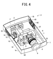
- FIG. 4 shows a perspective view of the outline of a liquid crystal projector of the present embodiment
- FIG. 5 shows a plan view of FIG. 4
- FIG. 6 shows a sectional view cut along the A-A line of FIG. 5 , respectively. It is to be noted that in FIGS. 4 to 6 , parts denoted with the same reference numerals as those of FIGS. 1 to 3 produce the same or similar effect or function, and the description thereof is omitted here.
- a liquid crystal projector P of the present embodiment unlike the liquid crystal projector P of Embodiment 1 described above, the inside of a main body 1 is not partitioned by a partition member 30.
- a duct 50 is provided around liquid crystal panels 5, 6 and 7, polarization plates 8A, 8B and a prism 25, and cold air subjected to heat exchange between the air and an evaporator 18 is supplied to the liquid crystal panels 5, 6 and 7, the polarization plates 8A, 8B and the prism 25 through the duct 50.
- the liquid crystal panels 5, 6 and 7 are not provided in a substantially sealed space, but the liquid crystal panels 5, 6 and 7, the polarization plates 8A, 8B and the prism 25 are arranged in a cooling air path constituted of the duct 50, and locally cooled by the cold air circulated through the duct 50.
- the duct 50 of the present embodiment is made of an insulating material.
- the insulating material include rubber plastic based materials such as hard vinyl chloride, a silicon resin, a fluorine resin, a phenol resin, a polycarbonate resin and a polystyrene resin having a thermal conductivity of about 0.1 W/(m•K) to 0.3 W/(m•K), vitreous materials such as quartz glass and a glass ceramic material having a thermal conductivity of about 1 W/(m•K) to 4 W/(m•K), fibrous insulating materials such as glass wool, rock wool and carbide cork having a thermal conductivity of 0.045 W/(m•K) or less, foam polystyrene, insulating materials for construction made of these materials and vacuum insulating materials made of the materials.
- a material having a thermal conductivity of 1 W/(m•K) or less may be used as the insulating material.
- the evaporator 18 constitutes a part of the duct 50, and cold air subjected to heat exchange between the air and this evaporator 16 can be circulated.
- the duct 50 is formed around the liquid crystal panels 5, 6 and 7 and the prism 25, and constituted of a cylindrical sealed path 50A substantially having a U-shape, and communication tubes 50B which connect blow-off ports 52 formed in one end of the sealed path 50A positioned above the liquid crystal panels 5, 6 and 7 to suction ports 53 formed in the other end of the sealed path 50A positioned under the liquid crystal panels 5, 6 and 7.
- the evaporator 18 and a fan 42 are installed in the sealed path 50A.
- the liquid crystal panels 5, 6 and 7 are installed (one of the three liquid crystal panels 5, 6 and 7 is installed in one communication tube 50B) and the polarization plates 8A, 8B are installed, respectively.
- the liquid crystal panels 5, 6 and 7 and the polarization plates 8A, 8B are arranged in the communication tube 50B with spaces being left between the panels and the plates.
- the polarization plate 8A is arranged with a space being left between the plate and one wall face of the communication tube 50B
- the polarization plate 8B is similarly arranged with a space being left between the plate and the other wall face of the communication tube 50B.
- this communication tube 50B is arranged so that the tube does not disturb light to irradiate the liquid crystal panels 5, 6 and 7 and the polarization plates 8A, 8B, and image information modulated by the liquid crystal panels 5, 6 and 7 and then sent to the prism 25, and the cold air subjected to the heat exchange between the air and the evaporator 16 is supplied to the liquid crystal panels 5, 6 and 7, the polarization plates 8A, 8B and the prism 25.
- a hole (not shown) is formed in a position corresponding to the polarization plate 8A (i.e., the one wall face of the communication tube 50B corresponding to the polarization plate 8A) on a polarization plate 8A side of the communication tube 50B, and this hole is connected to an opening of a box member 27 in which a light path is formed (not shown in FIG. 6 ).
- a hole 55 is formed in a position corresponding to the polarization plate 8B (i.e., the other wall face of the communication tube 50B corresponding to the polarization plate 8B) on a polarization plate 8B side of the communication tube 50B.
- This hole 55 has substantially the same shape as the outer shape of the prism 25, one face of the prism 25 abuts on the inner surface of the hole 55, or the one face is fitted into the hole 55 to close this hole. Furthermore, the prism 25 is attached to the hole 55 with a space being left between the prism and each polarization plate 8B.
- the duct 50 When the duct 50 is formed as described above, the duct does not disturb the light to irradiate the liquid crystal panels 5, 6 and 7 and the polarization plates 8A, 8B, and the image information modulated by the liquid crystal panels 5, 6 and 7 and then sent to the prism 25, but the inside of the duct 50 has a sealed structure or a semi-sealed structure, and the air subjected to the heat exchange between the air and the evaporator 16, cooled and circulated through the duct 50 can be supplied to the liquid crystal panels 5, 6 and 7, the polarization plates 8A, 8B and the prism 25.
- the air cooled by taking the heat from the air by the refrigerant in the evaporator 18 is discharged into the communication tube 50B through the respective blow-off ports 52 ... formed right above the liquid crystal panels 5, 6 and 7 and the polarization plates 8A, 8B by the fan 42 installed in the sealed path 50A of the duct 50, and the air is supplied to the liquid crystal panels 5, 6 and 7, the polarization plates 8A, 8B and the prism 25.
- the air flowing through the blow-off ports 52 into the communication tube 50B passes through gaps formed between the liquid crystal panels 5, 6 and 7 and the polarization plates 8A provided in this communication tube 50B, between the liquid crystal panels 5, 6 and 7 and the polarization plates 8B, between the polarization plate 8A and the one wall face of the communication tube 50B (i.e., the hole connected to the opening of the box member 27) and between the polarization plate 8B and the other wall face of the communication tube 50B (i.e., the prism 25).
- the liquid crystal panels 5, 6 and 7, the polarization plates 8A, 8B and the prism 25 release the heat to the air (the cold air), and are cooled.
- the air receiving the heat and heated by the liquid crystal panels 5, 6 and 7, the polarization plates 8A, 8B and the prism 25 is sucked into the sealed path 50A through the suction ports 53 formed right under the liquid crystal panels 5, 6 and 7 and the polarization plates 8A, 8B, respectively, to reach the evaporator 18.
- the air performs heat exchange between the air and the refrigerant flowing through the evaporator 18, is cooled, and is again supplied to the liquid crystal panels 5, 6 and 7, the polarization plates 8A, 8B and the prism 25 through the blow-off ports 52 by the fan 42. This cycle is repeated.
- the polarization plates 8A, 8B and the prism 25 can be cooled without being influenced by the outside air temperature in the same manner as in the above embodiment.
- the cold air subjected to the heat exchange between the air and the evaporator 18 can constantly be supplied to the liquid crystal panels 5, 6 and 7, the polarization plates 8A, 8B and the prism 25, and hence the amount of the heat to be released is remarkably increased as compared with a conventional example where the outside air is supplied to the liquid crystal panels. Therefore, the fan can be miniaturized to achieve the reduction of an installation space. Moreover, the amount of the air to be blown by the fan can be decreased to achieve the decrease of noise. Furthermore, as compared with the conventional thermoelectric cooling, an energy efficiency can remarkably be improved.
- the duct 50 is provided with a sealed structure, or a semi-sealed structure, the cold air subjected to the heat exchange between the air and the evaporator 16 is supplied to the liquid crystal panels 5, 6 and 7, the polarization plates 8A, 8B and the prism 25, and the cold air subjected to the heat exchange between the air and the evaporator 16 can be circulated.
- the cold air subjected to the heat exchange between the air and the evaporator 16 is more effectively supplied to the liquid crystal panels 5, 6 and 7, the polarization plates 8A, 8B and the prism 25, and the heat release effect of the liquid crystal panels 5, 6 and 7, the polarization plates 8A, 8B and the prism 25 can further be promoted.
- the heat of the liquid crystal panels 5, 6 and 7, the polarization plates 8A, 8B and the prism 25 is received by the refrigerant of the evaporator 18, conveyed to a radiator 14 by the refrigerant, released to the air in the radiator 14 and then discharged to the outside through air holes 37, so that it is possible to securely eliminate a disadvantage that the heat generated by the liquid crystal panels 5, 6 and 7 is confined in the main body 1 and raises an internal temperature to cause a secondary damage on peripheral components.
- the liquid crystal panels 5, 6 and 7, the polarization plates 8A, 8B and the prism 25 can efficiently be cooled, and the liquid crystal projector having a high performance can be provided at a low cost.
- the amounts of the heat to be generated by rays of colors R, G and B to irradiate the liquid crystal panels 5, 6 and 7, respectively, are large in order of B, G and R. Therefore, the arrangement of the fan 42 and the shape of the duct 50 are taken into consideration so that the amounts of the cold air to be supplied to the liquid crystal panels 5, 6 and 7 are large in this order.
- the diameters of the blow-off port 52 and the suction port 53 provided above and under the liquid crystal panel irradiated with the ray of the color B having the largest amount of the heat to be generated are set to the largest diameter
- the diameters of the blow-off port 52 and the suction port 53 provided above and under the liquid crystal panel irradiated with the ray of G are set to a smaller diameter
- the diameters of the blow-off port 52 and the suction port 53 provided above and under the liquid crystal panel irradiated with the ray of R having the smallest amount of the heat to be generated are set to the smallest diameter.
- the amount of the air to be blown may be adjusted.
- the duct 50 of the present embodiment is constituted of the sealed path 50A and the communication tubes 50B, but this sealed path 50A and the communication tubes 50B may detachably be attached to the main body 1. Furthermore, the duct 50 may further be constituted of a plurality of members detachably provided in the main body 1.
- the duct 50 when the duct 50 is constituted of the plurality of members detachably provided in the main body 1, an assembling operation during production can smoothly be performed. Furthermore, even during repair or the like, a removal operation can easily be performed, or the assembling operation after the repair can easily be performed.
- the duct 50 attached to the inside of the main body 1 when the duct 50 attached to the inside of the main body 1 is removed from the main body 1 during the repair, a portion to be repaired in the main body 1 can easily be repaired, or a breakdown portion can easily be removed, and a repair operation can easily be performed. Moreover, after the end of the repair, the duct 50 can easily be attached to the main body 1.
- the evaporator 18, the fan 42, the liquid crystal panels 5, 6 and 7, the polarization plates 8A, 8B and the prism 25 provided in the duct 50 can easily be removed or assembled, and repair operability can remarkably be improved.
- the evaporator 16 constitutes a part of the duct 50, but the present invention is not limited to this embodiment, and the evaporator 16 may be provided in the duct 50 so that the cold air subjected to the heat exchange between the air and the evaporator 16 can be circulated.
- the compressor 12 and the radiator 14 are provided in the main body 1, but the present invention is not limited to these embodiments, and they may be arranged on the bottom surface of the main body 1.
- the main body 1 is made of a material excellent in heat release properties (in the embodiments, magnesium is used as the material) as described above, the compressor 12 and the radiator 14 are allowed to release the heat, and it is possible to prevent a disadvantage that the heat of the compressor 12 and the radiator 14 is transmitted to the inside of the main body 1.
- the liquid crystal projector has been described as one example of the projector, but the projector of the present invention is not limited to this liquid crystal projector, and may be any projector including a main body provided with a light source, an optical element which processes light emitted from this light source in accordance with image information and a projection lens which projects a processed projection optical image onto a screen. Even when the present invention is applied to, for example, a DLP projector (DLP (registered trademark)), the present invention is effective.
- DLP registered trademark
Landscapes
- Physics & Mathematics (AREA)
- Engineering & Computer Science (AREA)
- Multimedia (AREA)
- Signal Processing (AREA)
- Nonlinear Science (AREA)
- General Physics & Mathematics (AREA)
- Mathematical Physics (AREA)
- Chemical & Material Sciences (AREA)
- Crystallography & Structural Chemistry (AREA)
- Optics & Photonics (AREA)
- Projection Apparatus (AREA)
- Liquid Crystal (AREA)
Abstract
Description
- The present invention relates to a projector which processes light emitted from a light source by an optical element to project a processed projection optical image onto a screen by a projection lens.
- Heretofore, this type of projector, for example, a liquid crystal projector has a constitution in which a light source, a liquid crystal panel (an optical element), a projection lens and the like are mounted in a main body. The liquid crystal panel is constituted of three liquid crystal panels for processing (modulating) color rays in accordance with image information generally as light bulbs. Moreover, light emitted from the light source is split into the color rays, processed (modulated) by the liquid crystal panels in accordance with the image information and synthesized as a projection optical image through a prism and the like. Then, the synthesized projection optical image is enlarged and projected onto a screen by the projection lens.
- In such a projector, the light source and the optical element (the liquid crystal panels, etc.) are heat generation sources to bring the inside of the main body into a heated state. Therefore, a plurality of fans are installed in the main body, and supply (blow) air outside the projector (the outside air) to the optical element and the light source to release the heat. In this case, the light source has a very high temperature of about +900°C, and the heat can sufficiently be released by the outside air, but the upper limit of the use temperature of the optical element is a comparatively low temperature. When, for example, the liquid crystal panels are used as the optical elements, the upper limit of the use temperature is about +70°C to +80°C. Therefore, the amount of the heat to be released from the optical elements is noticeably influenced by an outside air temperature. That is, when the outside air temperature is low, the optical elements can sufficiently release the heat to the supplied outside air. However, when the outside air temperature is high, the amount of the air to be blown by the fans needs to be increased to secure the amount of the heat to be released. Therefore, noise due to the operation of the fans increases, and a problem also occurs that power consumption remarkably soars.
- Moreover, the outside air receiving the heat is released to the outside, but this released outside air is again sucked by the fans and supplied to the projector. There also occurs a problem that a so-called short cycle of the air after the heat release is generated, and any excellent heat release effect cannot be obtained.
- To solve such a problem, it has been suggested that low-temperature air be produced by thermoelectric cooling, to cool the liquid crystal panels (the optical elements) (e.g., see Japanese Patent Application Laid-Open No.
2005-121250 - The problem of the noise can be solved by such thermoelectric cooling, but such thermoelectric cooling has a poor energy efficiency, and a heat generating section for the thermoelectric cooling is integrally constituted. Therefore, means for releasing the heat to the outside air (a heat sink or the fans) is required near a cooling target, and a problem has occurred that a spatial restriction is generated to remarkably lower a degree of freedom in design.
- The present invention has been developed to solve a conventional technical problem, and an object thereof is to provide a projector capable of efficiently cooling an optical element while decreasing the generation of noise as much as possible.
- The projector of the present invention comprises a main body provided with a light source, an optical element which processes light emitted from this light source in accordance with image information and a projection lens which projects a processed projection optical image onto a screen, and further comprises a cooling apparatus in which a compressor, a radiator, a pressure reducing unit and an evaporator provided in the main body constitute a refrigerant circuit, characterized in that air subjected to heat exchange between the air and the evaporator is supplied to the optical element to cool the optical element.
- The projector of a second aspect of the invention is characterized in that in the invention of a first aspect, the inside of the main body is partitioned into a first zone in which the light source is provided and a second zone in which the optical element is provided and which is sealed, and the air subjected to the heat exchange between the air and the evaporator is circulated through this second zone.
- The projector of a third aspect of the invention is characterized in that in the invention of the first aspect or the second aspect, the inside of the main body is partitioned into the first zone and the second zone by a partition member, and this partition member is made of an insulating material.
- The projector of a fourth aspect of the invention is characterized in that in the invention of the third aspect, the partition member is constituted of a plurality of plate members, and detachably provided in the main body.
- The projector of a fifth aspect of the invention is characterized in that in the invention of the first aspect, cold air subjected to the heat exchange between the air and the evaporator is supplied to the optical element through a duct.
- The projector of a sixth aspect of the invention is characterized in that in the invention of the fifth aspect, the evaporator constitutes a part of the duct or is provided in this duct, and the duct is made of an insulating material, and constituted so that the cold air subjected to the heat exchange between the air and the evaporator is circulated through the duct.
- The projector of a seventh aspect of the invention is characterized in that in the invention of the fifth aspect or the sixth aspect, the duct is constituted of a plurality of members detachably provided in the main body.
- The projector of an eighth aspect of the invention is characterized in that in the invention according to any one of the first to seventh aspects, the optical element includes a liquid crystal panel, polarization plates provided on the incidence side and the emission side of this liquid crystal panel, and a prism.
- According to the present invention, the projector comprises the main body provided with the light source, the optical element which processes the light emitted from this light source in accordance with the image information and the projection lens which projects the processed projection optical image onto the screen, and the projector further comprises the cooling apparatus in which the compressor, the radiator, the pressure reducing unit and the evaporator provided in the main body constitute the refrigerant circuit, and the air subjected to the heat exchange between the air and the evaporator is supplied to the optical element to cool the optical element. Therefore, the optical element can be cooled without being influenced by an outside air temperature. In consequence, the optical element can always be kept at a constant temperature.
- Moreover, the cold air subjected to the heat exchange between the air and the evaporator can constantly be supplied to the optical element. Therefore, a fan can be miniaturized, the amount of air to be blown by the fan can be decreased, and hence the reduction of an installation space and the decrease of noise can be achieved. Furthermore, an energy efficiency can be improved.
- Furthermore, when heat exchange is performed between the air heated by heat generated by the optical element and a refrigerant flowing through the evaporator of the cooling apparatus, the heat of the optical element can be conveyed by the refrigerant. Therefore, unlike a case where the optical element is cooled by cooling electrons, a degree of freedom in spatial layout design improves.
- Additionally, as in the second aspect of the invention, the inside of the main body is partitioned into the first zone in which the light source is provided and the second zone in which the optical element is provided and which is sealed, and the air subjected to the heat exchange between the air and the evaporator is circulated through this second zone. In this case, the optical element can be separated from the light source having a higher temperature, and it is possible to eliminate a disadvantage that the optical element is influenced by the heat from the light source. In consequence, a further cooling effect can be secured. Furthermore, any outside air does not enter the second zone, and the second zone constitutes a sealed space through which the air is circulated. Therefore, the whole second zone can homogeneously be cooled. Moreover, any dust or mote does not enter the zone from the outside air, and hence any filter is not necessary, so that the improvement of the quality of the optical element and the decrease of cost can be achieved.
- Moreover, as in the third aspect of the invention, the inside of the main body is partitioned into the first zone and the second zone by the partition member, and this partition member is made of the insulating material, whereby it is possible to eliminate a disadvantage that the optical element in the second zone is influenced by the heat from the light source in the second zone.
- Furthermore, as in the fourth aspect of the invention, the partition member is constituted of the plurality of plate members, and detachably provided in the main body, whereby an assembling operation during production, a removal operation during repair or the like, or an assembling operation after the repair can easily be performed.
- Additionally, in the first aspect of the invention, as in the fifth aspect of the invention, the cold air subjected to the heat exchange between the air and the evaporator is supplied to the optical element through the duct, whereby the cold air subjected to the heat exchange between the air and the evaporator can efficiently be supplied to the optical element, and the heat release effect of the optical element can be promoted.
- Moreover, as in the sixth aspect of the invention, the evaporator constitutes a part of the duct or is provided in the duct, and the duct is made of the insulating material, and constituted so that the cold air subjected to the heat exchange between the air and the evaporator can be circulated through the duct. In consequence, the cold air subjected to the heat exchange between the air and the evaporator can more effectively be supplied to the optical element, and the heat release effect of the optical element can further be promoted.
- Furthermore, as in the seventh aspect of the invention, the duct is constituted of the plurality of members detachably provided in the main body, whereby the assembling operation during the production, the removal operation during the repair or the like or the assembling operation after the repair can easily be performed. In particular, the removal or assembling of each device provided in the duct can easily be performed, and operability can remarkably be improved.
- In particular, as in the eighth aspect of the invention, the optical element includes the liquid crystal panel, the polarization plates provided on the incidence side and the emission side of this liquid crystal panel, and the prism, so that according to the first to seventh aspects of the invention, while decreasing the generation of the noise of the projector including the liquid crystal panel, the polarization plates and the prism as much as possible, the liquid crystal panel, the polarization plates and the prism can efficiently be cooled.
-
-
FIG. 1 is a perspective view showing the outline of a liquid crystal projector of one embodiment of the present invention; -
FIG. 2 is a plan view showing the outline of the liquid crystal projector of the embodiment of the present invention; -
FIG. 3 is a perspective view of a cooling apparatus of the liquid crystal projector of the present embodiment; -
FIG. 4 is a perspective view showing the outline of a liquid crystal projector of another embodiment of the present invention; -
FIG. 5 is a plan view showing the outline of the liquid crystal projector of the other embodiment of the present invention; and -
FIG. 6 is a sectional view cut along the A-A line ofFIG. 4 . - The present invention relates to a projector, and an object thereof is to efficiently cool an optical element while solving a problem of noise generated in a case where outside air is supplied to the optical element by a fan to release heat, and a problem of an energy efficiency due to the cooling of the optical element by thermoelectric cooling. The object of efficiently cooling the optical element while decreasing the generation of the noise as much an possible is realized by disposing a cooling apparatus in which a compressor, a radiator, a pressure reducing unit and an evaporator provided in a main body constitute a refrigerant circuit and supplying air subjected to heat exchange between the air and the evaporator to the optical element to cool the optical element. Hereinafter, embodiments of the present invention will be described in detail with reference to the drawings.
-
FIG. 1 is a schematic perspective view showing a projector of one embodiment of the present invention, andFIG. 2 is a plan view ofFIG. 1 . The projector of the embodiment is a liquid crystal projector P having amain body 1 provided with alight source 2, a homogeneous illuminationoptical system 3, a color splitting optical system (not shown), anoptical element 4, aprojection lens 9 and acooling apparatus 10 for theoptical element 4. Themain body 1 is a flat housing made of a material excellent in heat release properties, for example, magnesium. It is to be noted that inFIGS. 1 and2 , for the description of each device provided in themain body 1, themain body 1 is shown by a flat section of a cut upper part. - The
light source 2 includes alamp 20 such as an extra high pressure mercury lamp, and areflector 21 for emitting forwards light (diverging light) diverging from the lamp (FIG. 2 ). Thelight source 2 of the embodiment has a constitution in which thereflectors 21 are attached to a plurality of (four)lamps 20, respectively, and the light source is received in alamp box 22 provided in themain body 1. - The homogeneous illumination
optical system 3 forms the light emitted from thelight source 2 into a parallel luminous flux having a homogeneous luminance distribution, and includes an integrator lens, a condensing lens, a total reflection mirror and the like. Moreover, the color splitting optical system splits the parallel luminous flux from the homogeneous illuminationoptical system 3 into color rays of colors R, G and B, and includes a reflecting mirror for splitting the parallel luminous flux from the homogeneous illuminationoptical system 3 into the colors, a prism for guiding the split color luminous fluxes to theoptical element 4 and the like. - The
optical element 4 includes three liquid crystal panels (LCD panels) 5, 6 and 7,polarization plates 8A provided on the incidence sides of theliquid crystal panels polarization plates 8B provided on the emission sides of theliquid crystal panels prism 25 and the like. Theliquid crystal panels liquid crystal panels prism 25 synthesizes the respective color rays to form a projection optical image. Thisprism 25 includes a reflective face constituted of an X-like dielectric multilayered film, and the light from theliquid crystal panels projection lens 9 enlarges and projects the projection optical image from theprism 25 onto a screen, and is detachably arranged in a hole (not shown) formed in a wall face of themain body 1. It is to be noted that inFIGS. 1 and2 ,reference numeral 27 is a box member which covers a light path for guiding the light emitted from thelight source 2 to theliquid crystal panels polarization plates box member 27, the path (the light path) is formed through which the light passes from thelight source 2 to thepolarization plates 8A on the incidence sides of theliquid crystal panels - An operation of the above constitution will be described. As shown by arrows in
FIG. 1 , the light emitted from thelight source 2 is formed into a parallel luminous flux having a homogeneous luminance distribution through the homogeneous illuminationoptical system 3, split into the rays of the colors R, G and B in the color splitting optical system, and guided through the incidence-side polarization plates 8A to the correspondingliquid crystal panels liquid crystal panels prism 25 through the emission-side polarization plates 8B, and then enlarged and projected onto the screen by theprojection lens 9. - Meanwhile, heretofore in the liquid crystal projector, the light source and the liquid crystal panels are heat generation sources to bring the inside of the main body into a heated state, and hence a plurality of fans are installed in the main body so that the air outside the main body is supplied to the liquid crystal panels and the light source by the fans, thereby releasing the heat. Specifically, one example will be described. After supplying the outside air to the liquid crystal panels to release the heat, the air passed through the liquid crystal panels is supplied to the light source to release the heat from the light source. Afterward, the air heated by the light source is discharged from the main body by the fans.
- The above light source has a considerably high temperature of about +900°C, and hence the air passed through the liquid crystal panels can be supplied to sufficiently release the heat. On the other hand, the upper limit of the use temperature of each liquid crystal panel is a comparatively low temperature of about +70°C to +80°C, and the liquid crystal panels need to be cooled to the upper limit temperature or less. In consequence, the amount of the heat to be released from the liquid crystal panels is noticeably influenced by an outside air temperature. That is, when the outside air temperature is low, the outside air supplied to the liquid crystal panels is low, and hence the heat can sufficiently be released by the outside air. However, in a case where the outside air temperature is high, when a large amount of outside air is not supplied to the liquid crystal panels by increasing the amount of the air to be blown by the fans or the like, the temperature of the liquid crystal panels cannot be kept at the upper limit of the use temperature or less. In consequence, the noise increases owing to the operation of the fans, and a problem also occurs that power consumption due to the operation of the fans remarkably soars.
- Furthermore, the outside air receiving the heat in the main body is discharged to the outside, but the discharged outside air is again sucked by the fans. There has been a problem that a so-called short cycle of the air after the heat release is generated. In this case, the outside air sucked by the fans performs heat exchange between the air and the light source, and is heated to the high temperature. Therefore, when such a short cycle is generated, the temperature of the liquid crystal panels might rise, and an excellent heat release effect cannot be obtained.
- On the other hand, it has been suggested that low-temperature air be produced by thermoelectric cooling, thereby cooling the liquid crystal panels, but such thermoelectric cooling has a poor energy efficiency, and a heat generating section for the thermoelectric cooling is integrally constituted. Therefore, means for releasing the heat to the outside air (a heat sink or the fans) is required near a cooling target, and a problem has occurred that a spatial restriction is generated to remarkably lower a degree of freedom in design.
- To solve the problems, the liquid crystal projector P of the present invention includes the
cooling apparatus 10 in themain body 1. That is, in themain body 1 of the liquid crystal projector P of the present invention, thecooling apparatus 10 is installed. Thiscooling apparatus 10 cools theliquid crystal panels polarization plates prism 25 and the like, and as shown inFIGS. 2 and3 , acompressor 12, aradiator 14, a capillary tube 16 (a pressure reducing unit of the present invention) and anevaporator 18 constitute a refrigerant circuit. That is, arefrigerant discharge tube 13 of thecompressor 12 is connected to an inlet of theradiator 14, and an outlet of theradiator 14 is connected to arefrigerant pipe 15 extending to thecapillary tube 16. Moreover, an outlet of thecapillary tube 16 is connected to an inlet of theevaporator 18 through arefrigerant pipe 17, and an outlet of theevaporator 18 is connected to arefrigerant introducing tube 11 of thecompressor 12, to constitute an annular refrigerant circuit. It is to be noted that in the present embodiment, thecapillary tube 16 is used as the unit for reducing the pressure of the refrigerant, but the pressure reducing unit is not limited to the capillary tube as long as the pressure of the refrigerant can be reduced to a predetermined pressure, and any unit, for example, an expansion valve may be used. - Furthermore, the inside of the
main body 1 of the liquid crystal projector P of the embodiment is partitioned into afirst zone 31 and a sealedsecond zone 32 by apartition member 30. Thepartition member 30 is made of an insulating material. Here, usable examples of the insulating material include rubber plastic based materials such as hard vinyl chloride, a silicon resin, a fluorine resin, a phenol resin, a polycarbonate resin and a polystyrene resin having a thermal conductivity of about 0.1 W/(m•K) to 0.3 W/(m•K), vitreous materials such as quartz glass and a glass ceramic material having a thermal conductivity of about 1 W/(m•K) to 4 W/(m•K), fibrous insulating materials such as glass wool, rock wool and carbide cork having a thermal conductivity of 0.045 W/(m•K) or less, foam polystyrene, insulating materials for construction made of these materials and vacuum insulating materials made of the materials. In addition, a material having a thermal conductivity of 1 W/(m•K) or less may be used as the insulating material. - In the embodiment, the
partition member 30 is attached to the substantial center of themain body 1 in a longitudinal direction (a lateral direction shown inFIG. 2 ) so as to extend from awall face 1A on one side to awall face 1B on the other side. The height dimension of thepartition member 30 is substantially equal to that of themain body 1. Moreover, a recessedportion 34 is formed near the center of thepartition member 30, and thebox member 27 is disposed in this recessedportion 34. That is, thepartition member 30 partitions the inside of the substantially wholemain body 1 excluding a light path formed in thebox member 27 into thefirst zone 31 and thesecond zone 32 in an insulating manner, to prevent heat movement in the space of the main body 1 (thefirst zone 31 and the second zone 32) outside thebox member 27. Moreover, thepartition member 30 is provided with two holes for pipe connection, and therefrigerant pipe 17 and therefrigerant introducing tube 11 of thecooling apparatus 10 extend through the holes and are connected to the holes, so that devices of thecooling apparatus 10 arranged in thefirst zone 31 are connected to devices of thecooling apparatus 10 arranged in thesecond zone 32. - Furthermore, the
wall face 1A of themain body 1 on the one side of thefirst zone 31 is provided withair holes 35 which connect the inside of thefirst zone 31 to the outside. Moreover, thewall face 1B of themain body 1 on the other side of thefirst zone 31 is provided withair holes 37 which are formed in positions substantially facing the air holes 35 to connect the inside of thefirst zone 31 to the outside, and twofans fans first zone 31 to discharge the air to the outside. - Moreover, the
light source 2, and thecompressor 12, theradiator 14 and thecapillary tube 16 of thecooling apparatus 10 are installed in thefirst zone 31. Thecompressor 12, theradiator 14 and thecapillary tube 16 of thecooling apparatus 10 are installed near the air holes 35 in thefirst zone 31 of themain body 1. In the embodiment, thecompressor 12 is arranged at a position which is closest to the air holes 35, theradiator 14 is arranged by the side of the compressor (on the side of thecompressor 12 opposite to the air holes 35), and afan 41 is provided by the side of the radiator 14 (on the side of theradiator 14 opposite to the compressor 12). Thefan 41 sucks the outside air through the air holes 35, supplies the sucked air (the outside air) to theradiator 14, and discharges the air into thefirst zone 31. - Furthermore, when the
fans fan 41 are operated, the outside air is sucked through the air holes 35 into thefirst zone 31 of themain body 1. The sucked outside air successively passes through thecompressor 12 and theradiator 14, and is sucked by thefan 41. At this time, when the sucked outside air is supplied to thecompressor 12, thecompressor 12 heated by the operation can be cooled. Furthermore, when the outside air passed through thecompressor 12 is allowed to flow into theradiator 14, the refrigerant flowing through theradiator 14 can be allowed to release heat. - In addition, the outside air sucked by the
fan 41 is discharged into thefirst zone 31, and supplied to thelight source 2 provided in thefirst zone 31. In consequence, thelight source 2 releases the heat to the supplied air, and is cooled. At this time, since thelight source 2 has a very high temperature as described above, even the air passed through theradiator 14 and heated by the refrigerant has a temperature remarkably lower than that of thelight source 2, and hence the heat can sufficiently be released by the outside air passed through theradiator 14. The air (the outside air supplied through the air holes 35) heated at a high temperature by thelight source 2 is then sucked by thefans main body 1. - It is to be noted that in the present embodiment, the
compressor 12 is arranged at the position which is closest to the air holes 35 as described above, and theradiator 14 is arranged by the side of the compressor (on the side of thecompressor 12 opposite to the air holes 35), but the present invention is not limited to this example. Theradiator 14 may be arranged at a position which is closest to the air holes 35, and thecompressor 12 may be arranged by the side of the radiator (on the side of theradiator 14 opposite to the air holes 35). - On the other hand, the
liquid crystal panels polarization plates prism 25, theevaporator 18 of thecooling apparatus 10 and the like are installed in thesecond zone 32. Thepolarization plates 8A are provided on the incidence sides of theliquid crystal panels polarization plates 8B are provided on the emission sides of theliquid crystal panels fan 42 is installed in the vicinity of theevaporator 18, thefan 42 circulates, through thesecond zone 32, the air subjected to the heat exchange between the air and the refrigerant in the evaporator 18 (in this case, the air is the air in the second zone 32), and the air can be supplied to theliquid crystal panels polarization plates prism 25 and the like installed in thesecond zone 32. - A cooling operation using the
cooling apparatus 10 of the present invention in the above constitution will be described. When thecompressor 12 is driven, the refrigerant having a low temperature and a low pressure is sucked through therefrigerant introducing tube 11 into a compression element (not shown), and is compressed in the element. The compressed refrigerant having a high temperature and a high pressure is discharged into therefrigerant discharge tube 13, and flows into theradiator 14. The refrigerant flowing into theradiator 14 performs the heat exchange between the refrigerant and the outside air supplied through the air holes 35 in the radiator, to release the heat. The refrigerant releasing the heat in theradiator 14 enters thecapillary tube 16 through therefrigerant pipe 15, the pressure of the refrigerant is reduced while the refrigerant passes through thecapillary tube 16, and in this state, the refrigerant flows into theevaporator 18. - The refrigerant flowing into the
evaporator 18 takes the heat from the air of thesecond zone 32 in the evaporator, to evaporate. On the other hand, after taking the heat from the air by the refrigerant in theevaporator 18, the cooled air (the cold air) is supplied to theliquid crystal panels polarization plates prism 25 and the like by thefan 42. In consequence, theliquid crystal panels polarization plates prism 25 and the like release the heat to such air, and are cooled. It is to be noted that the refrigerant receiving the heat of the second zone 32 (theliquid crystal panels polarization plates prism 25, etc.) by theevaporator 18 is sucked and compressed by thecompressor 12 through therefrigerant introducing tube 11, flows into theradiator 14 and releases the heat to the blown outside air by theradiator 14. This cycle is repeated. - Thus, according to the liquid crystal projector P of the present invention, the
cooling apparatus 10 is disposed in themain body 1, and the air subjected to the heat exchange between the air and theevaporator 18 of thecooling apparatus 10 can be supplied to theliquid crystal panels polarization plates prism 25 and the like provided in thesecond zone 32 by thefan 42 to cool the same. In consequence, theliquid crystal panels polarization plates prism 25 and the like can be cooled without being influenced by the outside air temperature, and the devices provided in thesecond zone 32, for example, theliquid crystal panels polarization plates prism 25 and the like can constantly be kept at an optimum constant temperature. - Moreover, since the cold air subjected to the heat exchange between the air and the
evaporator 18 can constantly be supplied to theliquid crystal panels polarization plates prism 25, the amount of the heat to be released can remarkably be increased as compared with a conventional example where the outside air is supplied to the liquid crystal panels. Therefore, the fans can be miniaturized to reduce an installation space. Moreover, the amount of the air to be blown by the fans can be decreased to achieve the decrease of the noise. Furthermore, as compared with conventional thermoelectric cooling, an energy efficiency can remarkably be improved. - Furthermore, when the air heated by the heat generated by the
liquid crystal panels evaporator 18 of thecooling apparatus 10 perform heat exchange therebetween, the heat of theliquid crystal panels radiator 14, so that unlike a case where the optical element is cooled by the thermoelectric cooling, a degree of freedom in spatial layout design (in the main body 1) increases. - Particularly in the present embodiment, the inside of the
main body 1 is partitioned into thefirst zone 31 provided with thelight source 2 and thesecond zone 32 provided with theliquid crystal panels partition member 30, and the air subjected to the heat exchange between the air and theevaporator 18 is circulated through thesecond zone 32, so that it is possible to securely eliminate a disadvantage that theliquid crystal panels polarization plates prism 25 are influenced by the heat from thelight source 2. In consequence, a further cooling effect can be secured. - Moreover, when the air subjected to the heat exchange between the air and the
evaporator 18 is circulated through thesecond zone 32 by thefan 42 to cool theliquid crystal panels polarization plates prism 25 and the like, the substantially sealedsecond zone 32 can homogeneously be cooled. That is, for example, in a case where evaporators are arranged close to theliquid crystal panels liquid crystal panels liquid crystal panels second zone 32 becomes higher than that of theliquid crystal panels second zone 32 becomes remarkably nonuniform. This causes a disadvantage that the cooledliquid crystal panels second zone 32, thepolarization plates prism 25 and the like, and it might be difficult to keep the temperature of theliquid crystal panels liquid crystal panels second zone 32 remarkably lowers. - However, according to the present invention, since the one
evaporator 18 and thefan 42 are installed in thesecond zone 32 and the air cooled by theevaporator 18 can be circulated through thesecond zone 32 by thefan 42, the inside of thesecond zone 32 can substantially homogeneously be cooled, and the above problems can be solved. - Moreover, in the
cooling apparatus 10, the heat of theliquid crystal panels polarization plates prism 25 is received by the refrigerant of theevaporator 18, conveyed to theradiator 14 by the refrigerant, released to the air in theradiator 14 and then discharged to the outside through the air holes 37, so that it is possible to securely eliminate a disadvantage that the heat generated by theliquid crystal panels main body 1 and raises an internal temperature to cause a secondary damage on peripheral components. - Furthermore, any outside air is not introduced into the
second zone 32 but the air in thesecond zone 32 is circulated through the zone. That is, thesecond zone 32 is a sealed space through which the air in thesecond zone 32 is circulated. Therefore, any dust or mote does not enter the zone from the outside air, and hence any filter is not necessary. In consequence, further cost decrease can be achieved. - It is to be noted that in the present embodiment, the
partition member 30 is constituted of one plate member attached to extend from thewall face 1A at one end to thewall face 1B at the other end, but the present invention is not limited to this example, and the partition member may be constituted of a plurality of plate members, for example, two plate members. One of the plate members may detachably be arranged between thebox member 27 and thewall face 1A, and the other plate member may detachably be arranged between thebox member 27 and thewall face 1B. Thus, when thepartition member 30 is constituted of a plurality of plate members, and detachably attached to themain body 1, an assembling operation during production can smoothly be performed. Moreover, even during repair or the like, a removal operation can easily be performed, or the assembling operation after the repair can easily be performed. - For example, when the
partition member 30 attached to the inside of themain body 1 is removed from themain body 1 during the repair, a portion to be repaired in themain body 1 can easily be repaired, or a breakdown portion can easily be removed, and a repair operation can easily be performed. Moreover, after the end of the repair, thepartition member 30 can easily be attached to themain body 1. Consequently, the improvement of repair operability can be achieved. - Next, another embodiment of the present invention will be described with reference to
FIGS. 4 to 6 .FIG. 4 shows a perspective view of the outline of a liquid crystal projector of the present embodiment,FIG. 5 shows a plan view ofFIG. 4 , andFIG. 6 shows a sectional view cut along the A-A line ofFIG. 5 , respectively. It is to be noted that inFIGS. 4 to 6 , parts denoted with the same reference numerals as those ofFIGS. 1 to 3 produce the same or similar effect or function, and the description thereof is omitted here. - In a liquid crystal projector P of the present embodiment, unlike the liquid crystal projector P of
Embodiment 1 described above, the inside of amain body 1 is not partitioned by apartition member 30. In this case, aduct 50 is provided aroundliquid crystal panels polarization plates prism 25, and cold air subjected to heat exchange between the air and anevaporator 18 is supplied to theliquid crystal panels polarization plates prism 25 through theduct 50. That is, in the liquid crystal projector P of the present embodiment, unlike the above embodiment, theliquid crystal panels liquid crystal panels polarization plates prism 25 are arranged in a cooling air path constituted of theduct 50, and locally cooled by the cold air circulated through theduct 50. - The
duct 50 of the present embodiment is made of an insulating material. Usable examples of the insulating material include rubber plastic based materials such as hard vinyl chloride, a silicon resin, a fluorine resin, a phenol resin, a polycarbonate resin and a polystyrene resin having a thermal conductivity of about 0.1 W/(m•K) to 0.3 W/(m•K), vitreous materials such as quartz glass and a glass ceramic material having a thermal conductivity of about 1 W/(m•K) to 4 W/(m•K), fibrous insulating materials such as glass wool, rock wool and carbide cork having a thermal conductivity of 0.045 W/(m•K) or less, foam polystyrene, insulating materials for construction made of these materials and vacuum insulating materials made of the materials. In addition, a material having a thermal conductivity of 1 W/(m•K) or less may be used as the insulating material. - Moreover, in the present embodiment, the
evaporator 18 constitutes a part of theduct 50, and cold air subjected to heat exchange between the air and thisevaporator 16 can be circulated. Theduct 50 is formed around theliquid crystal panels prism 25, and constituted of a cylindrical sealedpath 50A substantially having a U-shape, andcommunication tubes 50B which connect blow-offports 52 formed in one end of the sealedpath 50A positioned above theliquid crystal panels ports 53 formed in the other end of the sealedpath 50A positioned under theliquid crystal panels path 50A, theevaporator 18 and afan 42 are installed. - Moreover, in the
communication tubes 50B, theliquid crystal panels liquid crystal panels communication tube 50B) and thepolarization plates liquid crystal panels polarization plates communication tube 50B with spaces being left between the panels and the plates. Moreover, thepolarization plate 8A is arranged with a space being left between the plate and one wall face of thecommunication tube 50B, and thepolarization plate 8B is similarly arranged with a space being left between the plate and the other wall face of thecommunication tube 50B. Furthermore, thiscommunication tube 50B is arranged so that the tube does not disturb light to irradiate theliquid crystal panels polarization plates liquid crystal panels prism 25, and the cold air subjected to the heat exchange between the air and theevaporator 16 is supplied to theliquid crystal panels polarization plates prism 25. - That is, a hole (not shown) is formed in a position corresponding to the
polarization plate 8A (i.e., the one wall face of thecommunication tube 50B corresponding to thepolarization plate 8A) on apolarization plate 8A side of thecommunication tube 50B, and this hole is connected to an opening of abox member 27 in which a light path is formed (not shown inFIG. 6 ). Moreover, ahole 55 is formed in a position corresponding to thepolarization plate 8B (i.e., the other wall face of thecommunication tube 50B corresponding to thepolarization plate 8B) on apolarization plate 8B side of thecommunication tube 50B. Thishole 55 has substantially the same shape as the outer shape of theprism 25, one face of theprism 25 abuts on the inner surface of thehole 55, or the one face is fitted into thehole 55 to close this hole. Furthermore, theprism 25 is attached to thehole 55 with a space being left between the prism and eachpolarization plate 8B. - When the
duct 50 is formed as described above, the duct does not disturb the light to irradiate theliquid crystal panels polarization plates liquid crystal panels prism 25, but the inside of theduct 50 has a sealed structure or a semi-sealed structure, and the air subjected to the heat exchange between the air and theevaporator 16, cooled and circulated through theduct 50 can be supplied to theliquid crystal panels polarization plates prism 25. - A cooling operation of the
liquid crystal panels cooling apparatus 10 is similar to that of the above embodiment and hence the description thereof is omitted. - The air cooled by taking the heat from the air by the refrigerant in the
evaporator 18 is discharged into thecommunication tube 50B through the respective blow-offports 52 ... formed right above theliquid crystal panels polarization plates fan 42 installed in the sealedpath 50A of theduct 50, and the air is supplied to theliquid crystal panels polarization plates prism 25. That is, the air flowing through the blow-offports 52 into thecommunication tube 50B passes through gaps formed between theliquid crystal panels polarization plates 8A provided in thiscommunication tube 50B, between theliquid crystal panels polarization plates 8B, between thepolarization plate 8A and the one wall face of thecommunication tube 50B (i.e., the hole connected to the opening of the box member 27) and between thepolarization plate 8B and the other wall face of thecommunication tube 50B (i.e., the prism 25). In consequence, theliquid crystal panels polarization plates prism 25 release the heat to the air (the cold air), and are cooled. - Then, the air receiving the heat and heated by the
liquid crystal panels polarization plates prism 25 is sucked into the sealedpath 50A through thesuction ports 53 formed right under theliquid crystal panels polarization plates evaporator 18. In the evaporator, the air performs heat exchange between the air and the refrigerant flowing through theevaporator 18, is cooled, and is again supplied to theliquid crystal panels polarization plates prism 25 through the blow-offports 52 by thefan 42. This cycle is repeated. - Even when the
duct 50 for supplying the cold air subjected to the heat exchange between the air and theevaporator 18 to theliquid crystal panels polarization plates prism 25 is formed around theliquid crystal panels polarization plates prism 25, theliquid crystal panels polarization plates prism 25 and the like can be cooled without being influenced by the outside air temperature in the same manner as in the above embodiment. Similarly, the cold air subjected to the heat exchange between the air and theevaporator 18 can constantly be supplied to theliquid crystal panels polarization plates prism 25, and hence the amount of the heat to be released is remarkably increased as compared with a conventional example where the outside air is supplied to the liquid crystal panels. Therefore, the fan can be miniaturized to achieve the reduction of an installation space. Moreover, the amount of the air to be blown by the fan can be decreased to achieve the decrease of noise. Furthermore, as compared with the conventional thermoelectric cooling, an energy efficiency can remarkably be improved. - Moreover, as in the present embodiment, the
duct 50 is provided with a sealed structure, or a semi-sealed structure, the cold air subjected to the heat exchange between the air and theevaporator 16 is supplied to theliquid crystal panels polarization plates prism 25, and the cold air subjected to the heat exchange between the air and theevaporator 16 can be circulated. In this constitution, the cold air subjected to the heat exchange between the air and theevaporator 16 is more effectively supplied to theliquid crystal panels polarization plates prism 25, and the heat release effect of theliquid crystal panels polarization plates prism 25 can further be promoted. - Furthermore, even in the present embodiment, in the
cooling apparatus 10, the heat of theliquid crystal panels polarization plates prism 25 is received by the refrigerant of theevaporator 18, conveyed to aradiator 14 by the refrigerant, released to the air in theradiator 14 and then discharged to the outside throughair holes 37, so that it is possible to securely eliminate a disadvantage that the heat generated by theliquid crystal panels main body 1 and raises an internal temperature to cause a secondary damage on peripheral components. - As described above in detail, according to the present invention, while decreasing the generation of the noise as much as possible, the
liquid crystal panels polarization plates prism 25 can efficiently be cooled, and the liquid crystal projector having a high performance can be provided at a low cost. - It is to be noted that although not especially described in the above embodiment, the amounts of the heat to be generated by rays of colors R, G and B to irradiate the
liquid crystal panels fan 42 and the shape of theduct 50 are taken into consideration so that the amounts of the cold air to be supplied to theliquid crystal panels off port 52 and thesuction port 53 provided above and under the liquid crystal panel irradiated with the ray of the color B having the largest amount of the heat to be generated are set to the largest diameter, the diameters of the blow-off port 52 and thesuction port 53 provided above and under the liquid crystal panel irradiated with the ray of G are set to a smaller diameter, and the diameters of the blow-off port 52 and thesuction port 53 provided above and under the liquid crystal panel irradiated with the ray of R having the smallest amount of the heat to be generated are set to the smallest diameter. Thus, the amount of the air to be blown may be adjusted. - Moreover, the
duct 50 of the present embodiment is constituted of the sealedpath 50A and thecommunication tubes 50B, but this sealedpath 50A and thecommunication tubes 50B may detachably be attached to themain body 1. Furthermore, theduct 50 may further be constituted of a plurality of members detachably provided in themain body 1. Thus, when theduct 50 is constituted of the plurality of members detachably provided in themain body 1, an assembling operation during production can smoothly be performed. Furthermore, even during repair or the like, a removal operation can easily be performed, or the assembling operation after the repair can easily be performed. - For example, when the
duct 50 attached to the inside of themain body 1 is removed from themain body 1 during the repair, a portion to be repaired in themain body 1 can easily be repaired, or a breakdown portion can easily be removed, and a repair operation can easily be performed. Moreover, after the end of the repair, theduct 50 can easily be attached to themain body 1. In particular, theevaporator 18, thefan 42, theliquid crystal panels polarization plates prism 25 provided in theduct 50 can easily be removed or assembled, and repair operability can remarkably be improved. - It is to be noted that in the present embodiment, the
evaporator 16 constitutes a part of theduct 50, but the present invention is not limited to this embodiment, and theevaporator 16 may be provided in theduct 50 so that the cold air subjected to the heat exchange between the air and theevaporator 16 can be circulated. - In the above embodiments, the
compressor 12 and theradiator 14 are provided in themain body 1, but the present invention is not limited to these embodiments, and they may be arranged on the bottom surface of themain body 1. In this case, when themain body 1 is made of a material excellent in heat release properties (in the embodiments, magnesium is used as the material) as described above, thecompressor 12 and theradiator 14 are allowed to release the heat, and it is possible to prevent a disadvantage that the heat of thecompressor 12 and theradiator 14 is transmitted to the inside of themain body 1. - Furthermore, in the embodiments, the liquid crystal projector has been described as one example of the projector, but the projector of the present invention is not limited to this liquid crystal projector, and may be any projector including a main body provided with a light source, an optical element which processes light emitted from this light source in accordance with image information and a projection lens which projects a processed projection optical image onto a screen. Even when the present invention is applied to, for example, a DLP projector (DLP (registered trademark)), the present invention is effective.
Claims (8)
- A projector comprising a main body provided with a light source, an optical element which processes light emitted from the light source in accordance with image information and a projection lens which projects a processed projection optical image onto a screen,
the projector further comprising:
a cooling apparatus in which a compressor, a radiator, a pressure reducing unit and an evaporator provided in the main body constitute a refrigerant circuit,
wherein air subjected to heat exchange between the air and the evaporator is supplied to the optical element to cool the optical element. - The projector according to claim 1, wherein the inside of the main body is partitioned into a first zone in which the light source is provided and a second zone in which the optical element is provided and which is sealed, and the air subjected to the heat exchange between the air and the evaporator is circulated through the second zone.
- The projector according to claim 2, wherein the inside of the main body is partitioned into the first zone and the second zone by a partition member, and the partition member is made of an insulating material.
- The projector according to claim 3, wherein the partition member is constituted of a plurality of plate members, and detachably provided in the main body.
- The projector according to claim 1, wherein cold air subjected to the heat exchange between the air and the evaporator is supplied to the optical element through a duct.
- The projector according to claim 5, wherein the evaporator constitutes a part of the duct or is provided in the duct, and the duct is made of an insulating material, and constituted so that the cold air subjected to the heat exchange between the air and the evaporator is circulated through the duct.
- The projector according to claim 5 or 6, wherein the duct is constituted of a plurality of members detachably provided in the main body.
- The projector according to any one of claims 1 to 7, wherein the optical element includes a liquid crystal panel, polarization plates provided on the incidence side and the emission side of the liquid crystal panel, and a prism.
Applications Claiming Priority (2)
| Application Number | Priority Date | Filing Date | Title |
|---|---|---|---|
| JP2006296305A JP4703539B2 (en) | 2006-10-31 | 2006-10-31 | projector |
| PCT/JP2007/070607 WO2008053744A1 (en) | 2006-10-31 | 2007-10-23 | Projector |
Publications (3)
| Publication Number | Publication Date |
|---|---|
| EP2085819A1 true EP2085819A1 (en) | 2009-08-05 |
| EP2085819A4 EP2085819A4 (en) | 2010-11-03 |
| EP2085819B1 EP2085819B1 (en) | 2013-01-23 |
Family
ID=39344087
Family Applications (1)
| Application Number | Title | Priority Date | Filing Date |
|---|---|---|---|
| EP07830341A Not-in-force EP2085819B1 (en) | 2006-10-31 | 2007-10-23 | Projector and cooling system |
Country Status (5)
| Country | Link |
|---|---|
| US (1) | US7993009B2 (en) |
| EP (1) | EP2085819B1 (en) |
| JP (1) | JP4703539B2 (en) |
| CN (1) | CN101535891B (en) |
| WO (1) | WO2008053744A1 (en) |
Cited By (2)
| Publication number | Priority date | Publication date | Assignee | Title |
|---|---|---|---|---|
| TWI417635B (en) * | 2009-12-30 | 2013-12-01 | Qisda Corp | Electronic apparatus and projector |
| EP2784577A1 (en) * | 2013-03-29 | 2014-10-01 | Funai Electric Co., Ltd. | Projector and head-up display device |
Families Citing this family (25)
| Publication number | Priority date | Publication date | Assignee | Title |
|---|---|---|---|---|
| WO2009150850A1 (en) * | 2008-06-13 | 2009-12-17 | パナソニック株式会社 | Image display device |
| JP5125877B2 (en) * | 2008-08-21 | 2013-01-23 | セイコーエプソン株式会社 | projector |
| US8093547B2 (en) | 2008-08-21 | 2012-01-10 | Seiko Epson Corporation | Projector and light source apparatus having a second reflector for reflecting light in infrared region |
| JP2010113204A (en) | 2008-11-07 | 2010-05-20 | Sanyo Electric Co Ltd | Projector apparatus |
| JP5161810B2 (en) * | 2009-02-25 | 2013-03-13 | 株式会社日立製作所 | Optical unit and projection type liquid crystal display device using the same |
| JP5223787B2 (en) * | 2009-06-12 | 2013-06-26 | ソニー株式会社 | Projector device |
| JP2011028030A (en) * | 2009-07-27 | 2011-02-10 | Panasonic Corp | Image display apparatus |
| JPWO2015008485A1 (en) * | 2013-07-19 | 2017-03-02 | 日本電気株式会社 | Cooling structure for hermetic casing and optical device using the same |
| EP2930420A1 (en) * | 2014-04-10 | 2015-10-14 | Johnson Controls Automotive Electronics SAS | Head up display projecting visual information onto a screen |
| CN104267566A (en) * | 2014-08-15 | 2015-01-07 | 广东威创视讯科技股份有限公司 | Air cooling heat dissipation device of projector |
| US9664987B2 (en) * | 2014-11-18 | 2017-05-30 | Canon Kabushiki Kaisha | Image display apparatus |
| JP2016200656A (en) * | 2015-04-08 | 2016-12-01 | セイコーエプソン株式会社 | projector |
| CN104834167A (en) * | 2015-05-12 | 2015-08-12 | 苏州佳世达光电有限公司 | Projection device |
| CN106444234A (en) * | 2016-09-21 | 2017-02-22 | 苏州佳世达光电有限公司 | Projection apparatus |
| JP6772831B2 (en) * | 2016-12-28 | 2020-10-21 | セイコーエプソン株式会社 | Heat transport equipment and projector |
| CN207216248U (en) * | 2017-05-11 | 2018-04-10 | 深圳市光峰光电技术有限公司 | Projector |
| JP7003563B2 (en) * | 2017-10-18 | 2022-01-20 | セイコーエプソン株式会社 | projector |
| JP2020020283A (en) * | 2018-07-31 | 2020-02-06 | セイコーエプソン株式会社 | Diaphragm compressor, cooler, projector, and method of compressing fluid |
| JP7144727B2 (en) * | 2018-08-08 | 2022-09-30 | セイコーエプソン株式会社 | Diaphragm compressor, projector, cooler, and fluid compression method |
| US11868033B2 (en) | 2018-08-27 | 2024-01-09 | Sony Group Corporation | Wavelength conversion element and light source module and projection display device |
| CN109068115B (en) * | 2018-09-26 | 2024-05-07 | 曦和科技(深圳)有限公司 | Novel projector structure |
| JP7322726B2 (en) * | 2020-01-29 | 2023-08-08 | セイコーエプソン株式会社 | projector |
| JP7052816B2 (en) * | 2020-03-19 | 2022-04-12 | セイコーエプソン株式会社 | projector |
| JP2021157057A (en) * | 2020-03-27 | 2021-10-07 | セイコーエプソン株式会社 | projector |
| JP2022070675A (en) * | 2020-10-27 | 2022-05-13 | セイコーエプソン株式会社 | projector |
Family Cites Families (11)
| Publication number | Priority date | Publication date | Assignee | Title |
|---|---|---|---|---|
| US4739396C1 (en) * | 1970-12-28 | 2002-07-09 | Gilbert P Hyatt | Projection display system |
| US6290360B1 (en) * | 1997-11-20 | 2001-09-18 | Hitachi, Ltd. | Liquid crystal projector, and projection lens unit, optical unit and cooling system for the same |
| JP2000267190A (en) * | 1999-03-19 | 2000-09-29 | Sanyo Electric Co Ltd | LCD projector |
| JP2000321668A (en) * | 1999-05-13 | 2000-11-24 | Sony Corp | Image display device and method |
| JP2003289195A (en) * | 2002-03-28 | 2003-10-10 | Mitsubishi Electric Corp | Cooling system |
| JP2004317956A (en) | 2003-04-18 | 2004-11-11 | Aisin Seiki Co Ltd | Imaging device, Peltier device |
| JP2005121250A (en) * | 2003-10-14 | 2005-05-12 | Seiko Epson Corp | Cooling device and rear projector |
| JP2005321525A (en) * | 2004-05-07 | 2005-11-17 | Seiko Epson Corp | projector |
| JP2006208488A (en) * | 2005-01-25 | 2006-08-10 | Seiko Epson Corp | Rear projector |
| TWI281376B (en) * | 2005-02-25 | 2007-05-11 | Foxconn Tech Co Ltd | Cooling device for plural heat generating components |
| US20060279706A1 (en) * | 2005-06-14 | 2006-12-14 | Bash Cullen E | Projection system |
-
2006
- 2006-10-31 JP JP2006296305A patent/JP4703539B2/en not_active Expired - Fee Related
-
2007
- 2007-10-23 US US12/513,103 patent/US7993009B2/en active Active
- 2007-10-23 EP EP07830341A patent/EP2085819B1/en not_active Not-in-force
- 2007-10-23 CN CN2007800407548A patent/CN101535891B/en not_active Expired - Fee Related
- 2007-10-23 WO PCT/JP2007/070607 patent/WO2008053744A1/en not_active Ceased
Cited By (2)
| Publication number | Priority date | Publication date | Assignee | Title |
|---|---|---|---|---|
| TWI417635B (en) * | 2009-12-30 | 2013-12-01 | Qisda Corp | Electronic apparatus and projector |
| EP2784577A1 (en) * | 2013-03-29 | 2014-10-01 | Funai Electric Co., Ltd. | Projector and head-up display device |
Also Published As
| Publication number | Publication date |
|---|---|
| JP2008112094A (en) | 2008-05-15 |
| US7993009B2 (en) | 2011-08-09 |
| CN101535891A (en) | 2009-09-16 |
| CN101535891B (en) | 2011-06-29 |
| JP4703539B2 (en) | 2011-06-15 |
| EP2085819A4 (en) | 2010-11-03 |
| EP2085819B1 (en) | 2013-01-23 |
| US20100066980A1 (en) | 2010-03-18 |
| WO2008053744A1 (en) | 2008-05-08 |
Similar Documents
| Publication | Publication Date | Title |
|---|---|---|
| EP2085819B1 (en) | Projector and cooling system | |
| US7237906B2 (en) | Projection-type image display apparatus | |
| KR100196681B1 (en) | Optics and Cooling Methods | |
| CN100369491C (en) | LCD Projectors and Lamps | |
| US6966653B2 (en) | Cooling device and optical device and projector having the cooling device | |
| CN100380228C (en) | Light source device and projector | |
| US20080236191A1 (en) | Apparatus including freezing unit and projector including freezing unit | |
| KR100688978B1 (en) | Projection device | |
| US20050190560A1 (en) | Light source device and projector | |
| CN101090627A (en) | Cooling device and projector | |
| US7896503B2 (en) | Image projecting apparatus | |
| KR100628726B1 (en) | Projection device | |
| JP2005121250A (en) | Cooling device and rear projector | |
| CN106054507A (en) | Projector | |
| JP2016200677A (en) | projector | |
| JP2009042379A (en) | Cooler for projector | |
| JP4491406B2 (en) | Lamp cooling structure, projection display device, and lamp cooling method | |
| JP2009222869A (en) | Projector | |
| JP2006208488A (en) | Rear projector | |
| JP2009075236A (en) | Cooling device for projector | |
| JP4811190B2 (en) | LCD display | |
| CN102109747B (en) | Projector and method for cooling lamps installed in projector | |
| JP2009222868A (en) | Projector | |
| CN100533262C (en) | Light source device, optical device, and image projection device | |
| JP5186252B2 (en) | projector |
Legal Events
| Date | Code | Title | Description |
|---|---|---|---|
| PUAI | Public reference made under article 153(3) epc to a published international application that has entered the european phase |
Free format text: ORIGINAL CODE: 0009012 |
|
| 17P | Request for examination filed |
Effective date: 20090428 |
|
| AK | Designated contracting states |
Kind code of ref document: A1 Designated state(s): AT BE BG CH CY CZ DE DK EE ES FI FR GB GR HU IE IS IT LI LT LU LV MC MT NL PL PT RO SE SI SK TR |
|
| DAX | Request for extension of the european patent (deleted) | ||
| A4 | Supplementary search report drawn up and despatched |
Effective date: 20101001 |
|
| RIC1 | Information provided on ipc code assigned before grant |
Ipc: G03B 21/16 20060101AFI20080606BHEP Ipc: H04N 9/31 20060101ALI20100927BHEP Ipc: H04N 5/74 20060101ALI20100927BHEP Ipc: G02F 1/13 20060101ALI20100927BHEP |
|
| GRAP | Despatch of communication of intention to grant a patent |
Free format text: ORIGINAL CODE: EPIDOSNIGR1 |
|
| RIC1 | Information provided on ipc code assigned before grant |
Ipc: G03B 21/16 20060101AFI20120904BHEP Ipc: G02F 1/1333 20060101ALI20120904BHEP Ipc: H04N 9/31 20060101ALI20120904BHEP Ipc: H04N 5/74 20060101ALI20120904BHEP |
|
| GRAS | Grant fee paid |
Free format text: ORIGINAL CODE: EPIDOSNIGR3 |
|
| GRAA | (expected) grant |
Free format text: ORIGINAL CODE: 0009210 |
|
| AK | Designated contracting states |
Kind code of ref document: B1 Designated state(s): AT BE BG CH CY CZ DE DK EE ES FI FR GB GR HU IE IS IT LI LT LU LV MC MT NL PL PT RO SE SI SK TR |
|
| REG | Reference to a national code |
Ref country code: GB Ref legal event code: FG4D |
|
| REG | Reference to a national code |
Ref country code: CH Ref legal event code: EP |
|
| REG | Reference to a national code |
Ref country code: AT Ref legal event code: REF Ref document number: 595261 Country of ref document: AT Kind code of ref document: T Effective date: 20130215 Ref country code: CH Ref legal event code: EP |
|
| REG | Reference to a national code |
Ref country code: IE Ref legal event code: FG4D |
|
| REG | Reference to a national code |
Ref country code: DE Ref legal event code: R096 Ref document number: 602007028270 Country of ref document: DE Effective date: 20130321 |
|
| REG | Reference to a national code |
Ref country code: AT Ref legal event code: MK05 Ref document number: 595261 Country of ref document: AT Kind code of ref document: T Effective date: 20130123 |
|
| REG | Reference to a national code |
Ref country code: LT Ref legal event code: MG4D |
|
| REG | Reference to a national code |
Ref country code: NL Ref legal event code: VDEP Effective date: 20130123 |
|
| PG25 | Lapsed in a contracting state [announced via postgrant information from national office to epo] |
Ref country code: BG Free format text: LAPSE BECAUSE OF FAILURE TO SUBMIT A TRANSLATION OF THE DESCRIPTION OR TO PAY THE FEE WITHIN THE PRESCRIBED TIME-LIMIT Effective date: 20130423 Ref country code: LT Free format text: LAPSE BECAUSE OF FAILURE TO SUBMIT A TRANSLATION OF THE DESCRIPTION OR TO PAY THE FEE WITHIN THE PRESCRIBED TIME-LIMIT Effective date: 20130123 Ref country code: AT Free format text: LAPSE BECAUSE OF FAILURE TO SUBMIT A TRANSLATION OF THE DESCRIPTION OR TO PAY THE FEE WITHIN THE PRESCRIBED TIME-LIMIT Effective date: 20130123 Ref country code: IS Free format text: LAPSE BECAUSE OF FAILURE TO SUBMIT A TRANSLATION OF THE DESCRIPTION OR TO PAY THE FEE WITHIN THE PRESCRIBED TIME-LIMIT Effective date: 20130523 Ref country code: SE Free format text: LAPSE BECAUSE OF FAILURE TO SUBMIT A TRANSLATION OF THE DESCRIPTION OR TO PAY THE FEE WITHIN THE PRESCRIBED TIME-LIMIT Effective date: 20130123 Ref country code: ES Free format text: LAPSE BECAUSE OF FAILURE TO SUBMIT A TRANSLATION OF THE DESCRIPTION OR TO PAY THE FEE WITHIN THE PRESCRIBED TIME-LIMIT Effective date: 20130504 Ref country code: BE Free format text: LAPSE BECAUSE OF FAILURE TO SUBMIT A TRANSLATION OF THE DESCRIPTION OR TO PAY THE FEE WITHIN THE PRESCRIBED TIME-LIMIT Effective date: 20130123 |
|
| PG25 | Lapsed in a contracting state [announced via postgrant information from national office to epo] |
Ref country code: SI Free format text: LAPSE BECAUSE OF FAILURE TO SUBMIT A TRANSLATION OF THE DESCRIPTION OR TO PAY THE FEE WITHIN THE PRESCRIBED TIME-LIMIT Effective date: 20130123 Ref country code: NL Free format text: LAPSE BECAUSE OF FAILURE TO SUBMIT A TRANSLATION OF THE DESCRIPTION OR TO PAY THE FEE WITHIN THE PRESCRIBED TIME-LIMIT Effective date: 20130123 Ref country code: FI Free format text: LAPSE BECAUSE OF FAILURE TO SUBMIT A TRANSLATION OF THE DESCRIPTION OR TO PAY THE FEE WITHIN THE PRESCRIBED TIME-LIMIT Effective date: 20130123 Ref country code: PT Free format text: LAPSE BECAUSE OF FAILURE TO SUBMIT A TRANSLATION OF THE DESCRIPTION OR TO PAY THE FEE WITHIN THE PRESCRIBED TIME-LIMIT Effective date: 20130523 Ref country code: GR Free format text: LAPSE BECAUSE OF FAILURE TO SUBMIT A TRANSLATION OF THE DESCRIPTION OR TO PAY THE FEE WITHIN THE PRESCRIBED TIME-LIMIT Effective date: 20130424 Ref country code: LV Free format text: LAPSE BECAUSE OF FAILURE TO SUBMIT A TRANSLATION OF THE DESCRIPTION OR TO PAY THE FEE WITHIN THE PRESCRIBED TIME-LIMIT Effective date: 20130123 Ref country code: PL Free format text: LAPSE BECAUSE OF FAILURE TO SUBMIT A TRANSLATION OF THE DESCRIPTION OR TO PAY THE FEE WITHIN THE PRESCRIBED TIME-LIMIT Effective date: 20130123 |
|
| PG25 | Lapsed in a contracting state [announced via postgrant information from national office to epo] |
Ref country code: RO Free format text: LAPSE BECAUSE OF FAILURE TO SUBMIT A TRANSLATION OF THE DESCRIPTION OR TO PAY THE FEE WITHIN THE PRESCRIBED TIME-LIMIT Effective date: 20130123 Ref country code: SK Free format text: LAPSE BECAUSE OF FAILURE TO SUBMIT A TRANSLATION OF THE DESCRIPTION OR TO PAY THE FEE WITHIN THE PRESCRIBED TIME-LIMIT Effective date: 20130123 Ref country code: DK Free format text: LAPSE BECAUSE OF FAILURE TO SUBMIT A TRANSLATION OF THE DESCRIPTION OR TO PAY THE FEE WITHIN THE PRESCRIBED TIME-LIMIT Effective date: 20130123 Ref country code: CZ Free format text: LAPSE BECAUSE OF FAILURE TO SUBMIT A TRANSLATION OF THE DESCRIPTION OR TO PAY THE FEE WITHIN THE PRESCRIBED TIME-LIMIT Effective date: 20130123 Ref country code: EE Free format text: LAPSE BECAUSE OF FAILURE TO SUBMIT A TRANSLATION OF THE DESCRIPTION OR TO PAY THE FEE WITHIN THE PRESCRIBED TIME-LIMIT Effective date: 20130123 |
|
| PG25 | Lapsed in a contracting state [announced via postgrant information from national office to epo] |
Ref country code: CY Free format text: LAPSE BECAUSE OF FAILURE TO SUBMIT A TRANSLATION OF THE DESCRIPTION OR TO PAY THE FEE WITHIN THE PRESCRIBED TIME-LIMIT Effective date: 20130123 |
|
| PLBE | No opposition filed within time limit |
Free format text: ORIGINAL CODE: 0009261 |
|
| STAA | Information on the status of an ep patent application or granted ep patent |
Free format text: STATUS: NO OPPOSITION FILED WITHIN TIME LIMIT |
|
| PG25 | Lapsed in a contracting state [announced via postgrant information from national office to epo] |
Ref country code: IT Free format text: LAPSE BECAUSE OF FAILURE TO SUBMIT A TRANSLATION OF THE DESCRIPTION OR TO PAY THE FEE WITHIN THE PRESCRIBED TIME-LIMIT Effective date: 20130123 |
|
| 26N | No opposition filed |
Effective date: 20131024 |
|
| REG | Reference to a national code |
Ref country code: DE Ref legal event code: R097 Ref document number: 602007028270 Country of ref document: DE Effective date: 20131024 |
|
| PG25 | Lapsed in a contracting state [announced via postgrant information from national office to epo] |
Ref country code: MC Free format text: LAPSE BECAUSE OF FAILURE TO SUBMIT A TRANSLATION OF THE DESCRIPTION OR TO PAY THE FEE WITHIN THE PRESCRIBED TIME-LIMIT Effective date: 20130123 |
|
| REG | Reference to a national code |
Ref country code: CH Ref legal event code: PL |
|
| GBPC | Gb: european patent ceased through non-payment of renewal fee |
Effective date: 20131023 |
|
| REG | Reference to a national code |
Ref country code: IE Ref legal event code: MM4A |
|
| PG25 | Lapsed in a contracting state [announced via postgrant information from national office to epo] |
Ref country code: GB Free format text: LAPSE BECAUSE OF NON-PAYMENT OF DUE FEES Effective date: 20131023 Ref country code: CH Free format text: LAPSE BECAUSE OF NON-PAYMENT OF DUE FEES Effective date: 20131031 Ref country code: LI Free format text: LAPSE BECAUSE OF NON-PAYMENT OF DUE FEES Effective date: 20131031 |
|
| REG | Reference to a national code |
Ref country code: FR Ref legal event code: ST Effective date: 20140630 |
|
| REG | Reference to a national code |
Ref country code: DE Ref legal event code: R119 Ref document number: 602007028270 Country of ref document: DE Effective date: 20140501 |
|
| PG25 | Lapsed in a contracting state [announced via postgrant information from national office to epo] |
Ref country code: FR Free format text: LAPSE BECAUSE OF NON-PAYMENT OF DUE FEES Effective date: 20131031 Ref country code: DE Free format text: LAPSE BECAUSE OF NON-PAYMENT OF DUE FEES Effective date: 20140501 |
|
| PG25 | Lapsed in a contracting state [announced via postgrant information from national office to epo] |
Ref country code: IE Free format text: LAPSE BECAUSE OF NON-PAYMENT OF DUE FEES Effective date: 20131023 |
|
| PG25 | Lapsed in a contracting state [announced via postgrant information from national office to epo] |
Ref country code: TR Free format text: LAPSE BECAUSE OF FAILURE TO SUBMIT A TRANSLATION OF THE DESCRIPTION OR TO PAY THE FEE WITHIN THE PRESCRIBED TIME-LIMIT Effective date: 20130123 |
|
| PG25 | Lapsed in a contracting state [announced via postgrant information from national office to epo] |
Ref country code: HU Free format text: LAPSE BECAUSE OF FAILURE TO SUBMIT A TRANSLATION OF THE DESCRIPTION OR TO PAY THE FEE WITHIN THE PRESCRIBED TIME-LIMIT; INVALID AB INITIO Effective date: 20071023 Ref country code: LU Free format text: LAPSE BECAUSE OF NON-PAYMENT OF DUE FEES Effective date: 20131023 |
|
| PG25 | Lapsed in a contracting state [announced via postgrant information from national office to epo] |
Ref country code: MT Free format text: LAPSE BECAUSE OF FAILURE TO SUBMIT A TRANSLATION OF THE DESCRIPTION OR TO PAY THE FEE WITHIN THE PRESCRIBED TIME-LIMIT Effective date: 20130123 |