EP2085689A2 - Beleuchtungsvorrichtung mit einer drehbaren Lampe - Google Patents
Beleuchtungsvorrichtung mit einer drehbaren Lampe Download PDFInfo
- Publication number
- EP2085689A2 EP2085689A2 EP08171863A EP08171863A EP2085689A2 EP 2085689 A2 EP2085689 A2 EP 2085689A2 EP 08171863 A EP08171863 A EP 08171863A EP 08171863 A EP08171863 A EP 08171863A EP 2085689 A2 EP2085689 A2 EP 2085689A2
- Authority
- EP
- European Patent Office
- Prior art keywords
- lamp
- socket structure
- lighting device
- socket
- lamp socket
- Prior art date
- Legal status (The legal status is an assumption and is not a legal conclusion. Google has not performed a legal analysis and makes no representation as to the accuracy of the status listed.)
- Withdrawn
Links
- 239000013013 elastic material Substances 0.000 claims description 3
- 238000005549 size reduction Methods 0.000 abstract description 2
- 230000004048 modification Effects 0.000 description 4
- 238000012986 modification Methods 0.000 description 4
- 238000006073 displacement reaction Methods 0.000 description 1
- 230000000694 effects Effects 0.000 description 1
- 239000000463 material Substances 0.000 description 1
- 230000001681 protective effect Effects 0.000 description 1
Images

Classifications
-
- F—MECHANICAL ENGINEERING; LIGHTING; HEATING; WEAPONS; BLASTING
- F21—LIGHTING
- F21V—FUNCTIONAL FEATURES OR DETAILS OF LIGHTING DEVICES OR SYSTEMS THEREOF; STRUCTURAL COMBINATIONS OF LIGHTING DEVICES WITH OTHER ARTICLES, NOT OTHERWISE PROVIDED FOR
- F21V19/00—Fastening of light sources or lamp holders
- F21V19/04—Fastening of light sources or lamp holders with provision for changing light source, e.g. turret
-
- F—MECHANICAL ENGINEERING; LIGHTING; HEATING; WEAPONS; BLASTING
- F21—LIGHTING
- F21Y—INDEXING SCHEME ASSOCIATED WITH SUBCLASSES F21K, F21L, F21S and F21V, RELATING TO THE FORM OR THE KIND OF THE LIGHT SOURCES OR OF THE COLOUR OF THE LIGHT EMITTED
- F21Y2103/00—Elongate light sources, e.g. fluorescent tubes
Definitions
- the present invention refers to a lighting device with a rotating lamp, of the type comprising a lamp socket structure apt to receive a lamp, e.g. in form of a fluorescent lamp.
- lamps having an oblong, substantially tubular shape having a single fixing end in correspondence of one of the two ends of the lamp.
- these lamps are formed by fluorescent lamps having a plugging mechanism in correspondence of a fixing end, operating as a base of the lamp and being apt to be plugged in a respective socket provided in the lamp socket structure.
- the space to be provided should be wide enough to allow the positioning of the whole lamp, comprising the base and the plug.
- an amount of that space, opposed to the plug remains clear and substantially unused.
- the lamp socket structures for the above mentioned kind of lamps should have be oversized, thus requiring a high use of space during storage and a higher cost for materials.
- the technical problem underlying the present invention is to provide a lighting device allowing to overcome the drawback mentioned above with reference to the known art.
- a device as above specified characterized by that the socket of the lamp and the lamp socket structure are connected by means of a joint allowing the socket to rotate relative to the lamp socket structure, from a plugging position, wherein the lamp is rotated and external to the lamp socket structure, to a working position wherein the lamp rests in the lamp socket structure.
- the main advantage of the lighting device according to the present invention lies in that it allows an easy plugging, without positioning the lamp in the lamp socket structure, and a size reduction of such structure.
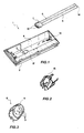
- a lighting device is overall shown with the reference number 1. It comprises a lamp socket structure 2 closed by a transparent wall in an operative arrangement, and comprising an opening 4 apt to house a lamp 5, in particular a fluorescent lamp.
- the lamp 5 is oblong shaped, substantially tubular, being formed of two sided parallel tubes, connected at one end. It comprises a single fixing end 6, opposed to the end connecting the two tubes, provided with a plugging mechanism 7 that should be plugged in a corresponding socket 8 provided in the lamp socket structure 2.
- the lamp socket structure 2 is oblong shaped, flat and rectangular, and it is suitable to be fixed on a wall to work as, e.g., an emergency lamp.
- the electronic circuitry (not shown) required for turning on and off the lamp.
- Such circuitry powered by a battery and/or by supply mains, is connected to the socket 8 by means of suitable cables.
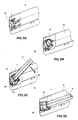
- the socket 8 comprises a plurality of holes 9 holding the electrical contacts connecting to plugs 10 of the plugging mechanism 7.
- the lamp socket structure 2 opening 4 also contains supports 12 for the lamp and a fixing device 13 of the lamp 5 free end 14, that will be described in the following.
- the lamp 5 socket 8 and the lamp socket structure 2 are connected by means of a joint allowing the socket 8 to rotate relative to the lamp socket structure 2.
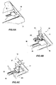
- the socket 8 could be rotated in a plugging position ( Figure 4A ), wherein the lamp 5 is rotated and it is external to the lamp socket structure 2 and, therefore, it can be easily plugged in the socket 8. Then, the lamp 5 is laid down ( figure 4B ) in the lamp socket structure 1 until it reaches an operative position ( figure 4C ), in which the transparent cover can be placed on the structure 2.
- the socket 8 is formed by an enbloc part that could be inserted in a frame 15 provided with a clamping device and made of elastic material, e.g. plastic, so as to be able to easily plug and unplug the socket 8 ( Figures 2 , 5A. 5B, 5C ).
- the frame 15 has pins on opposed ends that can be inserted in suitable seats in the lamp socket structure 2.
- the pins can be formed in the structure 2 and the seats in the frame 15.
- the enbloc socket 8 is provided with pins or holes apt to cooperate with corresponding holes or pins of the lamp socket structure 2.
- the device 1 comprises the above mentioned fixing device 13 of the lamp 5 free end 14.
- It comprises a seat 16 obtained on the opening 4 bottom of the lamp socket structure 2, into which a fixing element 17 is inserted so that it can move longitudinally, i.e. parallel to the lamp 5 development.
- the seat 16 comprises an inserting hole of said element 17 and a longitudinal guide 18, at the sides thereof pawls 19 being provided ( Figure 6A ).
- the fixing element 17 has a pair of elastic arms 20 with an end shaped such that it realizes a clamping spike cooperating with the pawls ( Figure 6B ). Accordingly, the fixing element 17 can be translated along the guide 18 remaining in a preset position, if it is not subjected to any load stress ( Figure 6C ).
- the pawls 19, forming on each side of the guide 18 a continuous rack, and the above described clamping spike allow to finely adjust the position of the fixing element 17, and to push it according to a direction concordant and opposite in sign to the unplugging one. They provide stopping means of the fixing element 17 in a certain position.
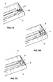
- the fixing element 17 comprises a tab 21 under which the free end of the lamp 5 is received.
- the lamp 5 is rotated so that it is adjacent to the lamp socket structure 2 in the opening 4 ( figure 7A ), a user can properly move the fixing element 17 of the device 13 ( figure 7B ) until the lamp 5 free end is compressed. Such end will be restrained by the tab 21 ( figure 7C ) that could be advantageously made of elastic material such that it can slightly provide an elastic pressure on the lamp 5.
- the lamp 5 remains fixed in its position and it not affected by vibrations or other movements that could cause the unplugging of the plug 7 from the socket 8.
- fixing device could envisage other modifications.
- it can envisage the use of a snap hook keeping the lamp 5 in place.
- it can comprise an elastic element on the opening 4 edge, eventually embedded in the same edge of the lamp socket structure 2.
- the present device could be modified to receive any substantially oblong shaped lamp, fluorescent, energy saving or of other type.
- connection between lamp and structure could be obtained by a device such as the one above described or even by a different device, e.g. with a threaded screw.
Landscapes
- Engineering & Computer Science (AREA)
- General Engineering & Computer Science (AREA)
- Fastening Of Light Sources Or Lamp Holders (AREA)
- Ultra Sonic Daignosis Equipment (AREA)
- Endoscopes (AREA)
- Non-Portable Lighting Devices Or Systems Thereof (AREA)
Applications Claiming Priority (1)
| Application Number | Priority Date | Filing Date | Title |
|---|---|---|---|
| IT000654A ITRM20070654A1 (it) | 2007-12-17 | 2007-12-17 | Dispositivo di illuminazione con lampada rotante |
Publications (2)
| Publication Number | Publication Date |
|---|---|
| EP2085689A2 true EP2085689A2 (de) | 2009-08-05 |
| EP2085689A3 EP2085689A3 (de) | 2012-02-29 |
Family
ID=40315832
Family Applications (1)
| Application Number | Title | Priority Date | Filing Date |
|---|---|---|---|
| EP08171863A Withdrawn EP2085689A3 (de) | 2007-12-17 | 2008-12-16 | Beleuchtungsvorrichtung mit einer drehbaren Lampe |
Country Status (2)
| Country | Link |
|---|---|
| EP (1) | EP2085689A3 (de) |
| IT (1) | ITRM20070654A1 (de) |
Citations (3)
| Publication number | Priority date | Publication date | Assignee | Title |
|---|---|---|---|---|
| EP0187296A2 (de) | 1985-01-09 | 1986-07-16 | Brökelmann, Jaeger & Busse GmbH & Co | Fassungsträger mit einer schwenkbaren Fassung für einseitig gesockelte Leuchtstofflampen |
| DE4411890A1 (de) | 1994-04-07 | 1995-10-12 | Ansorg Gmbh | Leuchte |
| EP1593908A2 (de) | 2004-05-04 | 2005-11-09 | Vossloh-Schwabe Deutschland GmbH | Leuchtstofflampen-Haltefeder |
-
2007
- 2007-12-17 IT IT000654A patent/ITRM20070654A1/it unknown
-
2008
- 2008-12-16 EP EP08171863A patent/EP2085689A3/de not_active Withdrawn
Patent Citations (3)
| Publication number | Priority date | Publication date | Assignee | Title |
|---|---|---|---|---|
| EP0187296A2 (de) | 1985-01-09 | 1986-07-16 | Brökelmann, Jaeger & Busse GmbH & Co | Fassungsträger mit einer schwenkbaren Fassung für einseitig gesockelte Leuchtstofflampen |
| DE4411890A1 (de) | 1994-04-07 | 1995-10-12 | Ansorg Gmbh | Leuchte |
| EP1593908A2 (de) | 2004-05-04 | 2005-11-09 | Vossloh-Schwabe Deutschland GmbH | Leuchtstofflampen-Haltefeder |
Also Published As
| Publication number | Publication date |
|---|---|
| EP2085689A3 (de) | 2012-02-29 |
| ITRM20070654A1 (it) | 2009-06-18 |
Similar Documents
| Publication | Publication Date | Title |
|---|---|---|
| ES2409204T3 (es) | Bloque de terminales eléctricos en serie | |
| CN103378615A (zh) | 充电装置 | |
| RU2399834C1 (ru) | Ламповое гнездо и осветительный прибор с таким гнездом | |
| CN114034006A (zh) | 照明设备 | |
| JP2006236877A (ja) | 照明装置 | |
| CN104879720A (zh) | 防触电灯头及双端进电灯管 | |
| CN203792201U (zh) | 一种pcb板夹具 | |
| EP2085689A2 (de) | Beleuchtungsvorrichtung mit einer drehbaren Lampe | |
| JP2016212993A (ja) | 照明器具、取付金具および取付金具セット | |
| CN205919137U (zh) | 一种螺口灯头及使用该螺口灯头的分体式led灯具 | |
| JP2025100886A (ja) | 光源用筐体、光源ユニット、照明器具 | |
| JP6726971B2 (ja) | 照明器具 | |
| JP6279333B2 (ja) | 照明用ユニット | |
| CN211952361U (zh) | 一种野营灯 | |
| ES2619195T3 (es) | Mando a distancia | |
| KR102083662B1 (ko) | 부착 기능을 갖는 멀티탭 | |
| CN204706694U (zh) | 一种可拉伸插座 | |
| JP5455950B2 (ja) | 工事用照明器具 | |
| CN201623610U (zh) | 电机的霍尔元件固定装置 | |
| CN2929995Y (zh) | 一种电源插座 | |
| JP6231390B2 (ja) | 発光パネル | |
| JP6215702B2 (ja) | 発光パネルの取付構造及び発光パネルの並設構造 | |
| JP5094437B2 (ja) | 照明器具 | |
| CN204216274U (zh) | 一种新型安全排插 | |
| CN104676451A (zh) | 一种磁吸壳体及使用该磁吸壳体的灯具 |
Legal Events
| Date | Code | Title | Description |
|---|---|---|---|
| PUAI | Public reference made under article 153(3) epc to a published international application that has entered the european phase |
Free format text: ORIGINAL CODE: 0009012 |
|
| AK | Designated contracting states |
Kind code of ref document: A2 Designated state(s): AT BE BG CH CY CZ DE DK EE ES FI FR GB GR HR HU IE IS IT LI LT LU LV MC MT NL NO PL PT RO SE SI SK TR |
|
| AX | Request for extension of the european patent |
Extension state: AL BA MK RS |
|
| RAP1 | Party data changed (applicant data changed or rights of an application transferred) |
Owner name: LINERGY S.R.L. |
|
| PUAL | Search report despatched |
Free format text: ORIGINAL CODE: 0009013 |
|
| AK | Designated contracting states |
Kind code of ref document: A3 Designated state(s): AT BE BG CH CY CZ DE DK EE ES FI FR GB GR HR HU IE IS IT LI LT LU LV MC MT NL NO PL PT RO SE SI SK TR |
|
| AX | Request for extension of the european patent |
Extension state: AL BA MK RS |
|
| RIC1 | Information provided on ipc code assigned before grant |
Ipc: F21V 19/04 20060101AFI20120125BHEP |
|
| 17P | Request for examination filed |
Effective date: 20120824 |
|
| AKX | Designation fees paid |
Designated state(s): AT BE BG CH CY CZ DE DK EE ES FI FR GB GR HR HU IE IS IT LI LT LU LV MC MT NL NO PL PT RO SE SI SK TR |
|
| GRAP | Despatch of communication of intention to grant a patent |
Free format text: ORIGINAL CODE: EPIDOSNIGR1 |
|
| STAA | Information on the status of an ep patent application or granted ep patent |
Free format text: STATUS: THE APPLICATION IS DEEMED TO BE WITHDRAWN |
|
| 18D | Application deemed to be withdrawn |
Effective date: 20130514 |