EP2085304A1 - Floor structure of scooter type vehicle - Google Patents
Floor structure of scooter type vehicle Download PDFInfo
- Publication number
- EP2085304A1 EP2085304A1 EP08018332A EP08018332A EP2085304A1 EP 2085304 A1 EP2085304 A1 EP 2085304A1 EP 08018332 A EP08018332 A EP 08018332A EP 08018332 A EP08018332 A EP 08018332A EP 2085304 A1 EP2085304 A1 EP 2085304A1
- Authority
- EP
- European Patent Office
- Prior art keywords
- side cover
- cover
- tunnel portion
- floor
- tunnel
- Prior art date
- Legal status (The legal status is an assumption and is not a legal conclusion. Google has not performed a legal analysis and makes no representation as to the accuracy of the status listed.)
- Granted
Links
Images




Classifications
-
- B—PERFORMING OPERATIONS; TRANSPORTING
- B62—LAND VEHICLES FOR TRAVELLING OTHERWISE THAN ON RAILS
- B62J—CYCLE SADDLES OR SEATS; AUXILIARY DEVICES OR ACCESSORIES SPECIALLY ADAPTED TO CYCLES AND NOT OTHERWISE PROVIDED FOR, e.g. ARTICLE CARRIERS OR CYCLE PROTECTORS
- B62J17/00—Weather guards for riders; Fairings or stream-lining parts not otherwise provided for
- B62J17/02—Weather guards for riders; Fairings or stream-lining parts not otherwise provided for shielding only the rider's front
-
- B—PERFORMING OPERATIONS; TRANSPORTING
- B62—LAND VEHICLES FOR TRAVELLING OTHERWISE THAN ON RAILS
- B62K—CYCLES; CYCLE FRAMES; CYCLE STEERING DEVICES; RIDER-OPERATED TERMINAL CONTROLS SPECIALLY ADAPTED FOR CYCLES; CYCLE AXLE SUSPENSIONS; CYCLE SIDECARS, FORECARS, OR THE LIKE
- B62K2202/00—Motorised scooters
Definitions
- the present invention relates generally to a scooter type vehicle and, in particular, to a floor structure with a tunnel portion advantageous to design.
- the separate decorative cover is arranged on the tunnel portion as described above, external appearance can be enhanced.
- the number of parts is increased because of addition of the decorative cover, which may probably lead to increased costs.
- the tunnel portion could integrally be molded with another cover part to reduce the number of parts. If the tunnel portion is integrally molded with a body cover below a seat, such a constituent part is enlarged, which may probably lower the flexibility of design. Thus, it is difficult to achieve a balance between the increased flexibility of design and the reduced number of parts.
- the present invention will solve such a problem.
- the invention according to claim 1 is a floor structure of a scooter type vehicle characterized by including: a pair of step floors on which feet of a rider sitting on a seat are placed; a tunnel portion upwardly bulging between the left and right step floors; a leg shield for covering from the front a foot of the rider sitting on the seat; and a tunnel portion side cover which covers at least a lateral surface of the tunnel portion; in that the leg shield includes a footrest portion extending forward from a corresponding step floor and a front side cover provided forward of the footrest portion to cover a lateral surface of a front end of a vehicle body; and in that the tunnel portion side cover is integrally molded with the front side cover.
- the invention of claim 2 is characterized in that in claim 1 described above, a front end of the tunnel portion side cover is joined to an upper end of the front side cover in an inverse V-shape and the front end of the step floor is allowed to conform to the inverse V-shape to integrally join the covers together.
- the invention of claim 3 is characterized in that in claim 1 described above, the tunnel portion side cover is provided at a portion above the footrest portion with a bulge portion protruding laterally of the vehicle.
- the invention of claim 4 is characterized in that in claim 1, 2 or 3, a front rising wall portion 61 joined to the footrest portion of the step floor is smoothly bent outwardly toward the front of the vehicle body.
- the invention of claim 5 is characterized in that in any one of claims 1 through 4 described above, a rear end of the tunnel portion side cover is continuously and integrally joined to a front end of a rear side cover disposed below the seat.
- the front side cover is integrally molded with the front side cover which is a relatively small part, the flexibility of designing the tunnel portion can be increased while reducing the number of parts. Further, since characteristic design such as forwardly extending the tunnel portion can be applied, the vehicle can be differentiated.
- the front end of the tunnel portion side cover is joined to the upper end of the front side cover in an inverse V-shape and the front end of the step floor is allowed to conform to the inverse V-shape to integrally join the covers together.
- the inverse V-shape can make an impression as an accent in view of design.
- a portion of the step floor is interposed between the footrest portion and the tunnel portion side cover to serve as a rising wall and to be continuous with the footrest portion. This makes it difficult for the occupant's foot to contact the tunnel portion side cover, which can prevent the tunnel portion side cover from getting dirty.
- the bulge portion can make the footrest portion less visible from the rider, the impression of the leg shield seen from the rider can be made expensive-looking.
- the foot when the occupant places a foot on the footrest, the foot can be placed such that its tiptoe is faced outwardly along the front rising wall portion.
- the occupant can mount on the vehicle in a more natural posture, which can improve the occupant comfort of the floor.
- tunnel portion side cover and the rear side cover are formed to be integrally continuous with each other from the front to rear of the vehicle, a sense of unity with respect to vehicle design can be improved.
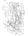
- Fig. 1 is a lateral view of a scooter type motorcycle embodying the present invention.
- This vehicle is provided with a low-floor type step floor 3 between a front wheel 1 and a rear wheel 2.
- An occupant 5 sits on a seat 4 disposed above the rear end of the step floor 3 and places her or his feet on the step floor 3.
- the step floor 3 is provided on each of the left and right of a central tunnel portion 7 put therebetween.
- a leg shield 8 is provided forward of the step floor 3 so as to cover the feet 6 from the front.
- the tunnel portion 7 is a portion of a body cover that is raised along the body center so as to be internally hollow.
- the seat 4 is of a tandem type in which feet 10 of a pillion passenger 9 are placed on pillion steps 12 provided on step holders 11.
- a handlebar shaft 14 of a handlebar 13 steered by the occupant 5 is turnably supported by a head pipe 16 provided at the front end of a body frame 15.
- the handlebar shaft 14 is connected at a lower end to a front fork 17 supporting the front wheel 1.
- the front wheel 1 is steered by the handlebar 13.
- the body frame 15 includes two upper and lower down frames and a rear frame 20.
- the down frames consist of a front upper frame 18 and a front lower frame 19 both extending obliquely downward and rearward from the head pipe 16.
- the rear frame 20 extends obliquely upward and rearward from a position close to the vertically intermediate portion of the front upper frame 18.
- the front lower frame 19 bends at a position below the step floor 3 to extend generally horizontally and rearward.
- the front lower frame 19 again bends at a position rearward of the step floor 3 to extend obliquely upward and rearward and connects with the anteroposteriorly intermediate portion of the rear frame 20.
- a vertically long fuel tank 21 is supported between the front upper frame 18 and the front lower frame 19 so as to locate its bottom at a position below the step floor 3.
- a fill port 22 provided at the upper portion of the fuel tank 21 is located at a position near the internal upper surface of the tunnel portion 7 so that fuel can be fed from above the tunnel portion 7.
- the front upper frame 18, the front lower frame 19 and the fuel tank 21 are arranged inside the space of the tunnel portion 7.
- a radiator 23 is located forward of the fuel tank 21. The arrangement of such heavy loads contributes to mass concentration and to lower the center of gravity.
- a front end of a swing type power unit 24 is swingably supported at a position near a portion of the front lower frame 19 that bends obliquely upward from the horizontal thereof.
- the rear wheel 2 is supported by a rear end of the power unit 24.
- the power unit 24 includes a forwardly-inclined in-line multi-cylinder engine 25.
- Reference numeral 26 denotes a side stand
- 27 denotes a main stand
- 28 denotes a battery supported by the rear frame 20 at a position below the rear part of the seat 4
- 29 denotes a rear cushion unit.
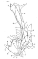
- Fig. 2 is a lateral view of the entire body cover that covers the vehicle body.
- the vehicle body cover includes a front cover 30 covering the head pipe 16 from the front; an inner cover 31 covering the head pipe 16 from the rear side; a tunnel portion side cover 32 forming a lateral portion of the tunnel portion 7; a floor panel 33 provided with the step floor 3 and with the leg shield 8; and a floor skirt panel 34 provided below the floor panel 33.
- the vehicle body further includes: a center cover 35 forming an upper portion of the tunnel portion 7 along with the inner cover 31; a rear side cover 36 serving as a seat lower cover; a rear side lower cover 37 attached below the rear side cover 36; and a rear side upper cover 38 attached to the rear end of the rear side cover 36.
- the tunnel portion side cover 32, the floor panel 33, the floor skirt panel 34, the rear side cover 36 and the rear side lower cover 37 are each provided as a pair of left and right ones.
- a headlight 40 is provided at a front portion of the front cover 30 and turn signal lamps 41 are provided at left and right front portions of the front cover 30.
- a windshield 42 is integrally joined to an upper portion of the front cover 30.
- the front cover 30 is continuously provided from the front portion to the horizontal portion.
- a meter panel 43 is provided on the rear surface side of the windshield 42 to cover the upper side opening of the front cover 30.
- the rear surface side of the front cover 30 is covered from the vehicle body rear side by the inner cover 31.
- a portion that is formed between the headlight 40 and each of the turn signal lamps 41 to reach the inner cover 31 serves an undercut slope 44 whose lower side portion extends into the inside of the vehicle body.
- a recessed portion is formed between such a portion and the inversely inclined tunnel portion side cover 32. This recessed portion is opened in the back and forth direction of the vehicle body to take in running air W from the front side and guide it to flow toward the rearward of the vehicle body.
- the inner cover 31 includes a pair of left and right inner cover uppers 45 and an inner cover lower 46.
- the inner cover uppers 45 are continuous with a rear portion of the undercut slope 44 and extend rearward.
- a lower portion of the inner cover lower 46 is continuous with the tunnel portion side cover 32.
- the rear surface of the inner cover lower 46 extends rearward to form an upper surface of the tunnel portion 7.
- An oil-feeding lid 47 is provided at a portion of the upper surface of the tunnel portion 7 so as to be openable and closable. If the oil-feeding lid 47 is opened while its rear side is turned upward around a front side hinge, fuel can be fed into the fill port 22 of the fuel tank 21 housed in the tunnel portion 7.
- the tunnel side cover 32 is composed of a rising wall-like main body portion 50 and a front side cover 51 by integral resin-molding.
- the main body portion 50 serves as a lateral wall of the tunnel portion.
- the front side cover 51 bends toward the front of a foot rest portion (described later) of the leg shield 8 to be vertically formed, and covers the front end lateral surface of the vehicle body.
- An upper edge front end of a joint portion 52 between the main body portion 50 and the front side cover 51 reaches the front lower end of the turn signal lamp 41.
- a front edge of the front side cover 51 is formed as a portion of the front edge of the entire body cover.
- the top end of the main body portion 50 appears to continuously extend to the front end of the vehicle body.
- a distinguishing design can be applied to extend the tunnel portion 7 to the front of the vehicle body, which can provide differentiation of vehicles.
- the floor panel 33 includes a lateral rising wall portion 60 and a front rising wall portion 61.
- the lateral rising wall portion 60 extends along the lower edge of the tunnel portion side cover 32 to form a lateral wall of the tunnel portion.
- the front rising wall portion 61 is a portion of the leg shield 8 and is formed generally triangular as viewed from the side.
- the inner cover 31, the center cover 35, the main body portion 50 of the tunnel portion side cover 32, and the lateral rising wall portion 60 and front rising wall portion 61 of the floor panel 33 form the tunnel portion 7.
- the front rising wall portion 61 is enclosed by the main body portion 50 and front side cover 51 of the tunnel portion side cover 32.
- the floor skirt panel 34 is as below.
- a front end upper portion extends around the front of the lower portion of the leg shield 8 and is joined to the lower end portion of the front side cover 51.
- a portion rearward of the front end upper portion is joined to the outer edge portion of the step floor 3.
- a front end of the rear side cover 36 is joined to the rear end of the main body portion 50 and the rear side lower cover 37 overlaps the lower end of the rear side cover 36. Since the rear side cover 36 and the rear side lower cover 37 are separated from each other, design flexibility can be increased by allowing the materials, colors or the like of the rear covers to differ from each other. Coloration of the body cover will be described later.
- the rear side upper cover 38 is attached to cover the respective rear ends of the rear side cover 36 and of the rear side lower cover 37.
- the step holder 11 is disposed in a space enclosed by the rear end of the lateral rising wall portion 60, the front lower edge of the rear side cover 36, the front edge of the rear side lower cover 37 and the rear edge of the floor skirt panel 34.
- the step holder 11 is a metal plate attached to a portion that is a rear portion of the front lower frame 19 and that extends obliquely upward toward the rear frame 20.
- the pillion step 12 is provided at the step holder 11 so as to be retractable.
- the floor panel 33 should basically have black colors because of serving as a foot-placed portion.
- the step holder 11 and the rear side lower cover 37 horizontally juxtaposed to the floor panel 33 are allowed to have the same colors, which can provide a sense of unity.
- the tunnel portion side cover 32 is allowed to have other colors (e.g. non-black colors such as white, red and the like) than those of the floor panel 33.
- the external colors of the vehicle are configured to realize the variation of design.
- the rear side cover 36, the front cover 30, the floor skirt panel 34 are allowed to have the same colors.
- the lateral surface of the body cover lateral portion can vertically be depicted in two-tone colors.
- the inner cover 31 may be allowed to have the same or different colors as or from those of the tunnel portion side cover 32.
- the tunnel portion side cover 32, the main body portion 50 and the front side cover 51 are formed into a single piece to increase the flexibility of design.
- the front side cover 51 may be separated from the main body portion 50 of the tunnel portion side cover 32 so as to be a separate member as in the traditional way. In such a case, it is desired that the front side cover 51 be united with another cover member in order to reduce the number of component parts. If the front side cover 51 is united with e.g. the leg shield 8, color is basically limited to black to eliminate the flexibility of coloration.
- the front side cover 51 is united with a naturally large-sized cover member such as the front cover 30, the floor skirt panel 34 or the like, resulting in further enlargement. Consequently, it is difficult to allow only the front side cover 51 among them to have uniquely free design, shape or the like. In addition, also a mold is enlarged. In short, it is a reality that it is difficult for the front side cover 51 to be united with such cover members.
- the present invention unites the relatively small-sized front side cover 51 with the main body portion 50 of the tunnel portion side cover 32. That is to say, the united cover is made not large-sized so much. Thus, it is possible to balance opposing requests, that is, a reduction in the number of component parts (a suppressed increase) and an improvement in the flexibility of design.
- tunnel portion side cover 32 and the rear side cover 36 are configured so as to be integrally continuous with each other from the front portion to rear portion of the vehicle, a sense of unity of vehicle design can be improved.
- Fig. 3 is a cross-sectional view taken along line 3-3 of Fig. 2 .
- the main body portion 50 is formed as a bulge portion 53 protruding above the inner cover 31.
- the leg shield 8 particularly, a footrest portion (described later) which is part of the leg shield and is a flat surface opposed to the rider side, cannot be seen from the rearward occupant.
- the design of the step floor 3 seen from the occupant can provide expensive-looking.
- a recessed groove is formed on the upper side of the bulge portion 53 and between the undercut slope 44 ( Fig. 2 ) of the front cover 30 and the inner cover 31.
- the bulge portion 53 can prevent running air passing through the recessed groove from flowing around the occupant's foot.
- a space enclosed by the inner cover 31 and by the main body portion 50 forms the tunnel portion 7.
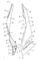
- Fig. 4 illustrates details of the tunnel portion side cover 32, A being a plan view and B being a lateral view.
- the main body portion 50 bends such that the anteroposteriorly intermediate portion most extends inwardly of the vehicle body to enlarge the width of the foot-placed portion of the step floor 3 described later, which makes foot-reaching performance satisfactory.
- an upper edge 50a bends to gradually protrude outwardly of the vehicle body toward the front from the inwardly extending portion, forming the bulge portion 53.
- the bulge portion 53 makes the leg shield 8 less visible from the rider's eyesight as described above.
- the upper edge 50a reaches the upper portion of the front side cover 51 therefrom and then bends again to extend inwardly of the vehicle body.
- the bulge portion 53 is formed as described above, the upper edge 50a and a lower edge 50c of edges forming the circumference of the main body portion 50 intersect each other at a point P of the anteroposteriorly intermediate portion as viewed from above.
- a joint portion between the front edge 50b and the lower edge 50c is located vehicle body-inside of the upper edge 50a.
- the lower edge 50c extends outward from the lower edge 50c and further extends rearward at a curvature larger than that of the upper edge 50a.
- the main body portion 50 is formed such that front and rear portions with the point P put therebetween are twisted inwardly and outwardly, i.e., reversely with each other.
- the front edge 50b of the main body portion 50 is inclined forwardly and obliquely upwardly so that a V-shaped space 54 as viewed from the side may be defined between the front edge 50b and the rear edge 51 b of the front side cover 51.
- the front edge 50b bends to extend inward of the upper edge 50a from the front to the rearward and connects with the front end of the lower edge 50c at the lowest portion.
- the upper edge 50a connects with the lower edge of the inner cover 31 and the front edge 50b and the lower edge 50c connect with an inward line of the floor panel 33 as viewed from the above.
- the front edge 51 a and rear edge 51 b of the front side cover 51 is generally parallel with each other and the lower edge 51 c connects with the front end upper portion of the floor skirt panel 34.
- the upper edge 50a is formed with engaging projections 55a, 55b, and 55c for attachment with the inner cover 31.
- the engaging projections 55a, 55b, and 55c project in the back and forth direction, are spaced from each other at appropriate intervals and are engaged with the lower end of the inner cover 31.
- the upper edge 50a is formed on the rear side with a stay 55d (A of Fig. 4 ) which projects generally horizontally and inwardly of the vehicle body and screwed to the inner cover 31.
- the upper edge 50a is formed at a rear end with a flange 55e which projects therefrom below the seat 4.
- the front edge 50b is formed at an upper portion with a boss 56a which projects inwardly of the vehicle body and is screwed to the upper end of the front rising wall portion 61.
- the front edge 50b is formed with a similar boss 56b at a vertically intermediate portion.
- Bosses 58a, 58b, and 58c are formed on the forward portion along the lower edge 50c to project inward of the vehicle body and screwed to the lateral rising wall portion 60.
- the rear edge 51 b, facing the space 54, of the front side cover 51 is formed like an outwardly bent flange, which is lapped on a front edge of the front rising wall portion 61.
- its upper side portion is engaged with the front rising wall portion 61 at an attachment portion 57a.
- the rear edge 51 b is formed with a fastening portion 57b at a lower end and screwed to the front edge lower portion of the front rising wall portion 61.
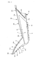
- Fig. 5 is a lateral view of the floor panel 33 and Fig. 6 is a plan view of Fig. 5 .
- the floor panel 33 is formed by uniting the step floor 3 with the leg shield 8.
- the step floor 3 includes a flat foot-placed portion 62 and the lateral rising wall portion 60.
- the leg shield 8 is formed like a forwardly upwardly inclined surface as viewed from the side and integrally includes a footrest portion 64 flat as viewed from above and the front rising wall portion 61. These portions are integrally formed as a whole to provide the floor panel 33.
- the foot-placed portion 62 and the footrest portion 64 are formed as a continuous plane, which is covered with a floor mat not shown.
- the foot 6 when the occupant 5 places a foot 6 on the footrest portion 64, the foot 6 can be placed such that its tiptoe is faced outwardly along the front rising wall portion 30.
- the occupant can mount on the vehicle in a more natural posture, which can improve occupant comfort.
- the upper edge 60a of the lateral rising wall portion 60 is formed with attachment projections 65a, 65b, and 65c in the back and forth direction.
- An upper edge 61 a of the front rising wall 61 is formed with an attachment projection 66a at a front end and with an attachment projection 66b at an intermediate portion rearward of the front end.
- a lower edge 61 b of the front rising wall portion 61 is provided with an engaging projection 67a on the upper side and with a boss 67b on the lower side.
- the upper edge of the floor skirt panel 34 is engaged with and joined to an outer edge 62a of the foot-placed portion 62 from the lower surface side.
- a stay 68 is formed on a rear extension of the outer edge 62a so as to project downward therefrom and is screwed to the floor skirt panel 34.
- Fig. 7 is a lateral view of a state where the tunnel portion side cover 32 is joined to the floor panel 33 and Fig. 8 is a plan view of Fig. 7 .
- the tunnel portion side cover 32 and the floor panel 33 are such that the lower edge 50c is joined to the upper edge 60a ( Fig. 8 ) and the bosses 58a, 58b, and 58c are coupled to the attachment projections 65a, 65b, and 65c, respectively.
- the front edge 50b is joined to the upper edge 61 a and the bosses 56a and 56b are coupled to the attachment projections 66a and 66b, respectively ( Fig. 7 ).
- the lower edge 61 b is joined to the rear edge 51 b and the attachment portions 57a and 57b are coupled to the engagement projection 67a and the boss 67b, respectively ( Fig. 7 ).
- the front end of the main body portion 50 of the tunnel portion side cover 32 is joined to the upper end of front side cover 51 to provide an inverse V-shape therebetween.
- the foot rest portion 64 which is a front end of the extension of the step floor 3 and the front rising wall portion 61 are formed so as to conform to the inverse V-shape. In this way, since such covers are integrally joined together, the inverse V-shaped portion can make an impression as an accent in view of design.
- a portion of the step floor 3 is interposed between the footrest portion 64 and the tunnel portion side cover 32 to serve as a rising wall and to be continuous with the footrest portion 64. This makes it difficult for the occupant's foot to contact the tunnel portion side cover 32, which can prevent the tunnel portion side cover 32 from getting dirty.
- Fig. 9 is a cross-sectional view taken along line 9-9 of Fig. 7 .
- the attachment projection 66a is lapped on the boss 56 from the inside of the vehicle body and is screwed with a tapping screw 70. The same applies to the attachment structure of the boss 56b with the attachment projection 66b.
- Fig. 10 illustrates a joint structure at an A-portion of Fig. 7 .
- Fig. 10A illustrates the boss 67b as viewed from arrow Z of Fig. 5 and
- Fig. 10B is a cross-sectional view illustrating the boss 67b taken along line 10-10 of Fig. 10A .
- the upper end portion of the floor skirt panel 34 is lapped on the boss 67b from the front thereof and the attachment portion 57b of the front side cover 51 is further lapped on the upper end portion of the floor skirt panel 34 from the front thereof.
- the three members are screw-joined together by being co-fastened to one another with a tapping screw 70 from the front of the vehicle body for screwing integration.
- Fig. 11 is a cross-sectional view taken along line 11-11 of Fig. 7 .
- the attachment projection 65a is lapped on the boss 56a from the inside of the vehicle body and screwed thereto with a tapping screw 70. The same applies to the attachment of the boss 56b with the attachment projection 65b and to the attachment of the boss 56c with the attachment projection 65c.
- the present invention is not limited to the embodiment described above but can be modified or applied in various ways within the principles thereof.
- the tunnel portion side cover 32 is not necessarily formed on each of the left and right of the tunnel portion 7.
- the tunnel portion side cover 32 can integrally be formed also on the upper surface of the tunnel portion 7.
- the invention is directed to increase the flexibility of design of a tunnel portion lateral surface without increasing the number of parts.
- Low-floor type step floors 3 and leg shields 8 forward of the corresponding step floors 3 are provided between a front wheel 1 and a rear wheel 2.
- a tunnel portion 7 is provided between the left and right step floors 3 and a seat 4 is disposed rearward of the step floors 3.
- a lateral surface of the tunnel portion 7 is formed of a tunnel portion side cover 32 and a floor panel 33.
- the tunnel portion side cover 32 is formed by uniting a main body portion 50 with a front side cover 51 forward of the leg shield 8.
- the tunnel portion side cover 32 is joined to the outer edge of the floor panel 33 integrally including a lateral rising wall portion 60, a front rising wall portion 61, the step floor 3 and the leg shield 8.
- the leg shield 8 is received in a generally V-shaped space defined between the main body portion 50 and the front side cover 51.
Landscapes
- Engineering & Computer Science (AREA)
- Mechanical Engineering (AREA)
- Automatic Cycles, And Cycles In General (AREA)
- Body Structure For Vehicles (AREA)
Abstract
Description
- The present invention relates generally to a scooter type vehicle and, in particular, to a floor structure with a tunnel portion advantageous to design.
- There is known a floor structure of a scooter type vehicle provided with left and right foot-placed step floors and with a tunnel portion raised between the step floors. In this floor structure, the design flexibility of the tunnel portion is increased by arranging a separate decorative cover on the tunnel portion. However, the design flexibility of the conventional tunnel portion has been low to meet a demand for a reduction in size because of straddle by an operator and for making it less noticeable (Japanese Patent No.
3938652 - If the separate decorative cover is arranged on the tunnel portion as described above, external appearance can be enhanced. However, the number of parts is increased because of addition of the decorative cover, which may probably lead to increased costs. It is conceivable that the tunnel portion could integrally be molded with another cover part to reduce the number of parts. If the tunnel portion is integrally molded with a body cover below a seat, such a constituent part is enlarged, which may probably lower the flexibility of design. Thus, it is difficult to achieve a balance between the increased flexibility of design and the reduced number of parts. The present invention will solve such a problem.
- To solve the above problem, the invention according to
claim 1 is a floor structure of a scooter type vehicle characterized by including: a pair of step floors on which feet of a rider sitting on a seat are placed; a tunnel portion upwardly bulging between the left and right step floors; a leg shield for covering from the front a foot of the rider sitting on the seat; and a tunnel portion side cover which covers at least a lateral surface of the tunnel portion; in that the leg shield includes a footrest portion extending forward from a corresponding step floor and a front side cover provided forward of the footrest portion to cover a lateral surface of a front end of a vehicle body; and in that the tunnel portion side cover is integrally molded with the front side cover. - The invention of claim 2 is characterized in that in
claim 1 described above, a front end of the tunnel portion side cover is joined to an upper end of the front side cover in an inverse V-shape and the front end of the step floor is allowed to conform to the inverse V-shape to integrally join the covers together. - The invention of
claim 3 is characterized in that inclaim 1 described above, the tunnel portion side cover is provided at a portion above the footrest portion with a bulge portion protruding laterally of the vehicle. - The invention of
claim 4 is characterized in that inclaim wall portion 61 joined to the footrest portion of the step floor is smoothly bent outwardly toward the front of the vehicle body. - The invention of
claim 5 is characterized in that in any one ofclaims 1 through 4 described above, a rear end of the tunnel portion side cover is continuously and integrally joined to a front end of a rear side cover disposed below the seat. - According to the invention of
claim 1, since the front side cover is integrally molded with the front side cover which is a relatively small part, the flexibility of designing the tunnel portion can be increased while reducing the number of parts. Further, since characteristic design such as forwardly extending the tunnel portion can be applied, the vehicle can be differentiated. - According to the invention of claim 2, the front end of the tunnel portion side cover is joined to the upper end of the front side cover in an inverse V-shape and the front end of the step floor is allowed to conform to the inverse V-shape to integrally join the covers together. Thus, the inverse V-shape can make an impression as an accent in view of design.
- In addition, a portion of the step floor is interposed between the footrest portion and the tunnel portion side cover to serve as a rising wall and to be continuous with the footrest portion. This makes it difficult for the occupant's foot to contact the tunnel portion side cover, which can prevent the tunnel portion side cover from getting dirty.
- According to the invention of
claim 3, since the bulge portion can make the footrest portion less visible from the rider, the impression of the leg shield seen from the rider can be made expensive-looking. - According to the invention of
claim 4, when the occupant places a foot on the footrest, the foot can be placed such that its tiptoe is faced outwardly along the front rising wall portion. Thus, the occupant can mount on the vehicle in a more natural posture, which can improve the occupant comfort of the floor. - According to the invention of
claim 5, since the tunnel portion side cover and the rear side cover are formed to be integrally continuous with each other from the front to rear of the vehicle, a sense of unity with respect to vehicle design can be improved. -
-
Fig. 1 is a lateral view of a scooter type motorcycle embodying the present invention. -
Fig. 2 is a lateral view of an overall cover that covers a vehicle body. -
Fig. 3 is a cross-sectional view taken along line 3-3 ofFig. 2 . -
Fig. 4 illustrates details of a tunnel side cover (A being a plan view and B being a lateral view). -
Fig. 5 is a lateral view of a floor panel. -
Fig. 6 is a plan view of the floor panel. -
Fig. 7 is a lateral view illustrating a state where the tunnel portion side cover is joined to the floor panel. -
Fig. 8 is a plan view ofFig. 7 . -
Fig. 9 is a cross-sectional view taken along line 9-9 ofFig. 7 . -
Fig. 10 illustrates a joint structure at an A-portion ofFig. 7 . -
Fig. 11 is a cross-sectional view taken along line 11-11 ofFig. 7 . - One embodiment will hereinafter be described with reference to the drawings.
-
Fig. 1 is a lateral view of a scooter type motorcycle embodying the present invention. This vehicle is provided with a low-floortype step floor 3 between afront wheel 1 and a rear wheel 2. Anoccupant 5 sits on aseat 4 disposed above the rear end of thestep floor 3 and places her or his feet on thestep floor 3. - The
step floor 3 is provided on each of the left and right of acentral tunnel portion 7 put therebetween. Aleg shield 8 is provided forward of thestep floor 3 so as to cover thefeet 6 from the front. Thetunnel portion 7 is a portion of a body cover that is raised along the body center so as to be internally hollow. Theseat 4 is of a tandem type in whichfeet 10 of apillion passenger 9 are placed onpillion steps 12 provided onstep holders 11. - A
handlebar shaft 14 of ahandlebar 13 steered by theoccupant 5 is turnably supported by ahead pipe 16 provided at the front end of abody frame 15. Thehandlebar shaft 14 is connected at a lower end to afront fork 17 supporting thefront wheel 1. Thus, thefront wheel 1 is steered by thehandlebar 13. - The
body frame 15 includes two upper and lower down frames and arear frame 20. The down frames consist of a frontupper frame 18 and a frontlower frame 19 both extending obliquely downward and rearward from thehead pipe 16. Therear frame 20 extends obliquely upward and rearward from a position close to the vertically intermediate portion of the frontupper frame 18. The frontlower frame 19 bends at a position below thestep floor 3 to extend generally horizontally and rearward. In addition, the frontlower frame 19 again bends at a position rearward of thestep floor 3 to extend obliquely upward and rearward and connects with the anteroposteriorly intermediate portion of therear frame 20. - A vertically
long fuel tank 21 is supported between the frontupper frame 18 and the frontlower frame 19 so as to locate its bottom at a position below thestep floor 3. Afill port 22 provided at the upper portion of thefuel tank 21 is located at a position near the internal upper surface of thetunnel portion 7 so that fuel can be fed from above thetunnel portion 7. The frontupper frame 18, the frontlower frame 19 and thefuel tank 21 are arranged inside the space of thetunnel portion 7. Aradiator 23 is located forward of thefuel tank 21. The arrangement of such heavy loads contributes to mass concentration and to lower the center of gravity. - A front end of a swing
type power unit 24 is swingably supported at a position near a portion of the frontlower frame 19 that bends obliquely upward from the horizontal thereof. The rear wheel 2 is supported by a rear end of thepower unit 24. - The
power unit 24 includes a forwardly-inclined in-line multi-cylinder engine 25.Reference numeral 26 denotes a side stand, 27 denotes a main stand, 28 denotes a battery supported by therear frame 20 at a position below the rear part of theseat - A description is hereinafter given of the body cover.
Fig. 2 is a lateral view of the entire body cover that covers the vehicle body. The vehicle body cover includes afront cover 30 covering thehead pipe 16 from the front; aninner cover 31 covering thehead pipe 16 from the rear side; a tunnel portion side cover 32 forming a lateral portion of thetunnel portion 7; afloor panel 33 provided with thestep floor 3 and with theleg shield 8; and afloor skirt panel 34 provided below thefloor panel 33. The vehicle body further includes: acenter cover 35 forming an upper portion of thetunnel portion 7 along with theinner cover 31; a rear side cover 36 serving as a seat lower cover; a rear sidelower cover 37 attached below therear side cover 36; and a rear sideupper cover 38 attached to the rear end of therear side cover 36. - These body cover constituent members are each made of resin. The tunnel
portion side cover 32, thefloor panel 33, thefloor skirt panel 34, therear side cover 36 and the rear sidelower cover 37 are each provided as a pair of left and right ones. - A
headlight 40 is provided at a front portion of thefront cover 30 andturn signal lamps 41 are provided at left and right front portions of thefront cover 30. Awindshield 42 is integrally joined to an upper portion of thefront cover 30. Thefront cover 30 is continuously provided from the front portion to the horizontal portion. Ameter panel 43 is provided on the rear surface side of thewindshield 42 to cover the upper side opening of thefront cover 30. The rear surface side of thefront cover 30 is covered from the vehicle body rear side by theinner cover 31. - A portion that is formed between the
headlight 40 and each of theturn signal lamps 41 to reach theinner cover 31 serves an undercutslope 44 whose lower side portion extends into the inside of the vehicle body. In addition, a recessed portion is formed between such a portion and the inversely inclined tunnelportion side cover 32. This recessed portion is opened in the back and forth direction of the vehicle body to take in running air W from the front side and guide it to flow toward the rearward of the vehicle body. - The
inner cover 31 includes a pair of left and rightinner cover uppers 45 and an inner cover lower 46. Theinner cover uppers 45 are continuous with a rear portion of the undercutslope 44 and extend rearward. A lower portion of the inner cover lower 46 is continuous with the tunnelportion side cover 32. The rear surface of the inner cover lower 46 extends rearward to form an upper surface of thetunnel portion 7. An oil-feeding lid 47 is provided at a portion of the upper surface of thetunnel portion 7 so as to be openable and closable. If the oil-feeding lid 47 is opened while its rear side is turned upward around a front side hinge, fuel can be fed into thefill port 22 of thefuel tank 21 housed in thetunnel portion 7. - Although detailed later, the tunnel side cover 32 is composed of a rising wall-like
main body portion 50 and a front side cover 51 by integral resin-molding. Themain body portion 50 serves as a lateral wall of the tunnel portion. The front side cover 51 bends toward the front of a foot rest portion (described later) of theleg shield 8 to be vertically formed, and covers the front end lateral surface of the vehicle body. An upper edge front end of ajoint portion 52 between themain body portion 50 and the front side cover 51 reaches the front lower end of theturn signal lamp 41. A front edge of the front side cover 51 is formed as a portion of the front edge of the entire body cover. - As described above, if the
front side cover 51 and themain body portion 50 are formed into a single piece, the top end of themain body portion 50 appears to continuously extend to the front end of the vehicle body. Thus, a distinguishing design can be applied to extend thetunnel portion 7 to the front of the vehicle body, which can provide differentiation of vehicles. - Although the
floor panel 33 is also detailed later, it includes a lateral risingwall portion 60 and a front risingwall portion 61. The lateral risingwall portion 60 extends along the lower edge of the tunnel portion side cover 32 to form a lateral wall of the tunnel portion. The front risingwall portion 61 is a portion of theleg shield 8 and is formed generally triangular as viewed from the side. - The
inner cover 31, thecenter cover 35, themain body portion 50 of the tunnelportion side cover 32, and the lateral risingwall portion 60 and front risingwall portion 61 of thefloor panel 33 form thetunnel portion 7. - The front rising
wall portion 61 is enclosed by themain body portion 50 and front side cover 51 of the tunnelportion side cover 32. - The
floor skirt panel 34 is as below. A front end upper portion extends around the front of the lower portion of theleg shield 8 and is joined to the lower end portion of thefront side cover 51. In addition, a portion rearward of the front end upper portion is joined to the outer edge portion of thestep floor 3. - A front end of the rear side cover 36 is joined to the rear end of the
main body portion 50 and the rear sidelower cover 37 overlaps the lower end of therear side cover 36. Since therear side cover 36 and the rear sidelower cover 37 are separated from each other, design flexibility can be increased by allowing the materials, colors or the like of the rear covers to differ from each other. Coloration of the body cover will be described later. The rear sideupper cover 38 is attached to cover the respective rear ends of therear side cover 36 and of the rear sidelower cover 37. - The
step holder 11 is disposed in a space enclosed by the rear end of the lateral risingwall portion 60, the front lower edge of therear side cover 36, the front edge of the rear sidelower cover 37 and the rear edge of thefloor skirt panel 34. - The
step holder 11 is a metal plate attached to a portion that is a rear portion of the frontlower frame 19 and that extends obliquely upward toward therear frame 20. Thepillion step 12 is provided at thestep holder 11 so as to be retractable. - A description is here given of coloration of the cover members. It is preferred that the
floor panel 33 should basically have black colors because of serving as a foot-placed portion. Thestep holder 11 and the rear sidelower cover 37 horizontally juxtaposed to thefloor panel 33 are allowed to have the same colors, which can provide a sense of unity. - On the other hand, the tunnel portion side cover 32 is allowed to have other colors (e.g. non-black colors such as white, red and the like) than those of the
floor panel 33. Thus, the external colors of the vehicle are configured to realize the variation of design. In this case, therear side cover 36, thefront cover 30, thefloor skirt panel 34 are allowed to have the same colors. Thus, the lateral surface of the body cover lateral portion can vertically be depicted in two-tone colors. Further, theinner cover 31 may be allowed to have the same or different colors as or from those of the tunnelportion side cover 32. - As described above, the tunnel
portion side cover 32, themain body portion 50 and the front side cover 51 are formed into a single piece to increase the flexibility of design. In particular, the front side cover 51 may be separated from themain body portion 50 of the tunnel portion side cover 32 so as to be a separate member as in the traditional way. In such a case, it is desired that the front side cover 51 be united with another cover member in order to reduce the number of component parts. If the front side cover 51 is united with e.g. theleg shield 8, color is basically limited to black to eliminate the flexibility of coloration. - However, the front side cover 51 is united with a naturally large-sized cover member such as the
front cover 30, thefloor skirt panel 34 or the like, resulting in further enlargement. Consequently, it is difficult to allow only the front side cover 51 among them to have uniquely free design, shape or the like. In addition, also a mold is enlarged. In short, it is a reality that it is difficult for the front side cover 51 to be united with such cover members. - In contrast to this, the present invention unites the relatively small-sized front side cover 51 with the
main body portion 50 of the tunnelportion side cover 32. That is to say, the united cover is made not large-sized so much. Thus, it is possible to balance opposing requests, that is, a reduction in the number of component parts (a suppressed increase) and an improvement in the flexibility of design. - Since the tunnel
portion side cover 32 and the rear side cover 36 are configured so as to be integrally continuous with each other from the front portion to rear portion of the vehicle, a sense of unity of vehicle design can be improved. -
Fig. 3 is a cross-sectional view taken along line 3-3 ofFig. 2 . Themain body portion 50 is formed as abulge portion 53 protruding above theinner cover 31. With this, theleg shield 8, particularly, a footrest portion (described later) which is part of the leg shield and is a flat surface opposed to the rider side, cannot be seen from the rearward occupant. Thus, the design of thestep floor 3 seen from the occupant can provide expensive-looking. - A recessed groove is formed on the upper side of the
bulge portion 53 and between the undercut slope 44 (Fig. 2 ) of thefront cover 30 and theinner cover 31. However, thebulge portion 53 can prevent running air passing through the recessed groove from flowing around the occupant's foot. A space enclosed by theinner cover 31 and by themain body portion 50 forms thetunnel portion 7. -
Fig. 4 illustrates details of the tunnelportion side cover 32, A being a plan view and B being a lateral view. Themain body portion 50 bends such that the anteroposteriorly intermediate portion most extends inwardly of the vehicle body to enlarge the width of the foot-placed portion of thestep floor 3 described later, which makes foot-reaching performance satisfactory. In addition, anupper edge 50a bends to gradually protrude outwardly of the vehicle body toward the front from the inwardly extending portion, forming thebulge portion 53. Thebulge portion 53 makes theleg shield 8 less visible from the rider's eyesight as described above. Theupper edge 50a reaches the upper portion of the front side cover 51 therefrom and then bends again to extend inwardly of the vehicle body. - Since the
bulge portion 53 is formed as described above, theupper edge 50a and alower edge 50c of edges forming the circumference of themain body portion 50 intersect each other at a point P of the anteroposteriorly intermediate portion as viewed from above. In the edge forward of the point P, a joint portion between thefront edge 50b and thelower edge 50c is located vehicle body-inside of theupper edge 50a. In the edge rearward of the point P, thelower edge 50c extends outward from thelower edge 50c and further extends rearward at a curvature larger than that of theupper edge 50a. In short, themain body portion 50 is formed such that front and rear portions with the point P put therebetween are twisted inwardly and outwardly, i.e., reversely with each other. - The
front edge 50b of themain body portion 50 is inclined forwardly and obliquely upwardly so that a V-shapedspace 54 as viewed from the side may be defined between thefront edge 50b and therear edge 51 b of thefront side cover 51. Thefront edge 50b bends to extend inward of theupper edge 50a from the front to the rearward and connects with the front end of thelower edge 50c at the lowest portion. - The
upper edge 50a connects with the lower edge of theinner cover 31 and thefront edge 50b and thelower edge 50c connect with an inward line of thefloor panel 33 as viewed from the above. Thefront edge 51 a andrear edge 51 b of the front side cover 51 is generally parallel with each other and the lower edge 51 c connects with the front end upper portion of thefloor skirt panel 34. - The
upper edge 50a is formed with engagingprojections inner cover 31. The engagingprojections inner cover 31. Theupper edge 50a is formed on the rear side with astay 55d (A ofFig. 4 ) which projects generally horizontally and inwardly of the vehicle body and screwed to theinner cover 31. Theupper edge 50a is formed at a rear end with aflange 55e which projects therefrom below theseat 4. - The
front edge 50b is formed at an upper portion with aboss 56a which projects inwardly of the vehicle body and is screwed to the upper end of the front risingwall portion 61. Thefront edge 50b is formed with asimilar boss 56b at a vertically intermediate portion. -
Bosses lower edge 50c to project inward of the vehicle body and screwed to the lateral risingwall portion 60. - The
rear edge 51 b, facing thespace 54, of the front side cover 51 is formed like an outwardly bent flange, which is lapped on a front edge of the front risingwall portion 61. In addition, its upper side portion is engaged with the front risingwall portion 61 at anattachment portion 57a. Therear edge 51 b is formed with afastening portion 57b at a lower end and screwed to the front edge lower portion of the front risingwall portion 61. These joint structures are described later. -
Fig. 5 is a lateral view of thefloor panel 33 andFig. 6 is a plan view ofFig. 5 . As shown inFigs. 5 and6 , thefloor panel 33 is formed by uniting thestep floor 3 with theleg shield 8. Thestep floor 3 includes a flat foot-placedportion 62 and the lateral risingwall portion 60. Theleg shield 8 is formed like a forwardly upwardly inclined surface as viewed from the side and integrally includes afootrest portion 64 flat as viewed from above and the front risingwall portion 61. These portions are integrally formed as a whole to provide thefloor panel 33. Incidentally, the foot-placedportion 62 and thefootrest portion 64 are formed as a continuous plane, which is covered with a floor mat not shown. - With this configuration, when the
occupant 5 places afoot 6 on thefootrest portion 64, thefoot 6 can be placed such that its tiptoe is faced outwardly along the front risingwall portion 30. Thus, the occupant can mount on the vehicle in a more natural posture, which can improve occupant comfort. - The
upper edge 60a of the lateral risingwall portion 60 is formed withattachment projections upper edge 61 a of the front risingwall 61 is formed with anattachment projection 66a at a front end and with anattachment projection 66b at an intermediate portion rearward of the front end. Alower edge 61 b of the front risingwall portion 61 is provided with an engagingprojection 67a on the upper side and with aboss 67b on the lower side. - The upper edge of the
floor skirt panel 34 is engaged with and joined to anouter edge 62a of the foot-placedportion 62 from the lower surface side. Astay 68 is formed on a rear extension of theouter edge 62a so as to project downward therefrom and is screwed to thefloor skirt panel 34. -
Fig. 7 is a lateral view of a state where the tunnel portion side cover 32 is joined to thefloor panel 33 andFig. 8 is a plan view ofFig. 7 . As shown inFigs. 7 and8 , the tunnelportion side cover 32 and thefloor panel 33 are such that thelower edge 50c is joined to theupper edge 60a (Fig. 8 ) and thebosses attachment projections front edge 50b is joined to theupper edge 61 a and thebosses attachment projections Fig. 7 ). - In addition, the
lower edge 61 b is joined to therear edge 51 b and theattachment portions engagement projection 67a and theboss 67b, respectively (Fig. 7 ). - Further, the front end of the
main body portion 50 of the tunnel portion side cover 32 is joined to the upper end of front side cover 51 to provide an inverse V-shape therebetween. Thefoot rest portion 64 which is a front end of the extension of thestep floor 3 and the front risingwall portion 61 are formed so as to conform to the inverse V-shape. In this way, since such covers are integrally joined together, the inverse V-shaped portion can make an impression as an accent in view of design. - In addition, a portion of the
step floor 3 is interposed between thefootrest portion 64 and the tunnel portion side cover 32 to serve as a rising wall and to be continuous with thefootrest portion 64. This makes it difficult for the occupant's foot to contact the tunnelportion side cover 32, which can prevent the tunnel portion side cover 32 from getting dirty. -
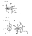
Fig. 9 is a cross-sectional view taken along line 9-9 ofFig. 7 . Theattachment projection 66a is lapped on the boss 56 from the inside of the vehicle body and is screwed with a tappingscrew 70. The same applies to the attachment structure of theboss 56b with theattachment projection 66b. -
Fig. 10 illustrates a joint structure at an A-portion ofFig. 7 .Fig. 10A illustrates theboss 67b as viewed from arrow Z ofFig. 5 andFig. 10B is a cross-sectional view illustrating theboss 67b taken along line 10-10 ofFig. 10A . As shown in the figures, the upper end portion of thefloor skirt panel 34 is lapped on theboss 67b from the front thereof and theattachment portion 57b of the front side cover 51 is further lapped on the upper end portion of thefloor skirt panel 34 from the front thereof. In addition, the three members are screw-joined together by being co-fastened to one another with a tappingscrew 70 from the front of the vehicle body for screwing integration. -
Fig. 11 is a cross-sectional view taken along line 11-11 ofFig. 7 . Theattachment projection 65a is lapped on theboss 56a from the inside of the vehicle body and screwed thereto with a tappingscrew 70. The same applies to the attachment of theboss 56b with theattachment projection 65b and to the attachment of the boss 56c with theattachment projection 65c. - Incidentally, the present invention is not limited to the embodiment described above but can be modified or applied in various ways within the principles thereof. For example, the tunnel portion side cover 32 is not necessarily formed on each of the left and right of the
tunnel portion 7. The tunnel portion side cover 32 can integrally be formed also on the upper surface of thetunnel portion 7. - The invention is directed to increase the flexibility of design of a tunnel portion lateral surface without increasing the number of parts.
- Low-floor
type step floors 3 andleg shields 8 forward of thecorresponding step floors 3 are provided between afront wheel 1 and a rear wheel 2. Atunnel portion 7 is provided between the left andright step floors 3 and aseat 4 is disposed rearward of thestep floors 3. A lateral surface of thetunnel portion 7 is formed of a tunnelportion side cover 32 and afloor panel 33. Of them, the tunnel portion side cover 32 is formed by uniting amain body portion 50 with a front side cover 51 forward of theleg shield 8. The tunnel portion side cover 32 is joined to the outer edge of thefloor panel 33 integrally including a lateral risingwall portion 60, a front risingwall portion 61, thestep floor 3 and theleg shield 8. Theleg shield 8 is received in a generally V-shaped space defined between themain body portion 50 and thefront side cover 51.
Claims (5)
- A floor structure of a scooter type vehicle comprising:a pair of step floors (3) on which feet of a rider sitting on a seat (4) are placed;a tunnel portion (7) upwardly bulging between the left and right step floors (3);a leg shield for covering from the front a foot (6) of the rider sitting on the seat (4); anda tunnel portion side cover (32) which covers at least a lateral surface of the tunnel portion (7);wherein the leg shield includes a footrest portion (64) extending forward from a corresponding step floor (3) and a front side cover (51) provided forward of the footrest portion (64) to cover a lateral surface of a front end of a vehicle body; andwherein the tunnel portion side cover (32) is integrally molded with the front side cover (51).
- The floor structure of a scooter type vehicle according to claim 1, wherein a front end of the tunnel portion side cover (32) is joined to an upper end of the front side cover (51) in an inverse V-shape and the front end of the step floor (3) is allowed to conform to the inverse V-shape to integrally join the covers together.
- The floor structure of a scooter type vehicle according to any one of claims 1 or 2, wherein the tunnel portion side cover (32) is provided at a portion above the footrest portion (64) with a bulge portion (53) protruding laterally of the vehicle.
- The floor structure of a scooter type vehicle according to claim 1, 2 or 3, wherein a front rising wall portion (61) joined to the footrest portion (64) of the step floor (3) is smoothly bent outwardly toward the front of the vehicle body.
- The floor structure of a scooter type vehicle according to any one of claims 1 through 4, wherein a rear end of the tunnel portion side cover (32) is continuously and integrally joined to a front end of a rear side cover (36) disposed below the seat (4).
Applications Claiming Priority (1)
| Application Number | Priority Date | Filing Date | Title |
|---|---|---|---|
| JP2008022181A JP5129592B2 (en) | 2008-01-31 | 2008-01-31 | Scooter type vehicle floor structure |
Publications (2)
| Publication Number | Publication Date |
|---|---|
| EP2085304A1 true EP2085304A1 (en) | 2009-08-05 |
| EP2085304B1 EP2085304B1 (en) | 2010-12-01 |
Family
ID=40096971
Family Applications (1)
| Application Number | Title | Priority Date | Filing Date |
|---|---|---|---|
| EP20080018332 Ceased EP2085304B1 (en) | 2008-01-31 | 2008-10-20 | Floor structure of scooter type vehicle |
Country Status (5)
| Country | Link |
|---|---|
| EP (1) | EP2085304B1 (en) |
| JP (1) | JP5129592B2 (en) |
| CN (1) | CN101497359B (en) |
| DE (1) | DE602008003743D1 (en) |
| ES (1) | ES2354849T3 (en) |
Cited By (2)
| Publication number | Priority date | Publication date | Assignee | Title |
|---|---|---|---|---|
| US8714620B1 (en) | 2013-01-31 | 2014-05-06 | Ford Global Technologies, Llc | Cowl trim with integrated footrest |
| EP3889015A1 (en) * | 2020-03-31 | 2021-10-06 | Yamaha Hatsudoki Kabushiki Kaisha | Straddled vehicle |
Families Citing this family (7)
| Publication number | Priority date | Publication date | Assignee | Title |
|---|---|---|---|---|
| CN103963884B (en) * | 2013-01-30 | 2018-04-20 | 雅马哈发动机株式会社 | Straddle type vehicle |
| KR101845643B1 (en) * | 2013-07-31 | 2018-04-04 | 혼다 기켄 고교 가부시키가이샤 | Motorcycle body cover structure |
| CN105793150B (en) * | 2013-12-04 | 2018-11-02 | 本田技研工业株式会社 | Side cover of motorcycle structure |
| JP6104304B2 (en) * | 2015-03-31 | 2017-03-29 | 本田技研工業株式会社 | Lower cowl structure of saddle riding type vehicle |
| WO2017168599A1 (en) * | 2016-03-29 | 2017-10-05 | 本田技研工業株式会社 | Attachment structure for motorcycle recoil starter |
| WO2017209699A1 (en) * | 2016-05-30 | 2017-12-07 | Honda Motor Co., Ltd | Cover structure around motorcycle step |
| CN113306661B (en) * | 2020-02-26 | 2022-08-16 | 雅马哈发动机株式会社 | Saddle-ride type vehicle |
Citations (4)
| Publication number | Priority date | Publication date | Assignee | Title |
|---|---|---|---|---|
| US20060021814A1 (en) * | 2004-07-27 | 2006-02-02 | Hirofumi Hasegawa | Wheeled vehicle with leg shield |
| US20060037798A1 (en) * | 2004-08-17 | 2006-02-23 | Toshihiko Konno | Wheeled vehicle with covers |
| US20060048991A1 (en) * | 2004-09-03 | 2006-03-09 | Naoto Sunaguchi | Vehicle |
| JP3938652B2 (en) | 2000-07-05 | 2007-06-27 | ヤマハ発動機株式会社 | Scooter type vehicle exterior structure |
Family Cites Families (2)
| Publication number | Priority date | Publication date | Assignee | Title |
|---|---|---|---|---|
| JPH06127449A (en) * | 1992-10-20 | 1994-05-10 | Mitsubishi Kasei Corp | Two-wheeled or three-wheeled vehicle body |
| JPH082463A (en) * | 1994-06-22 | 1996-01-09 | Suzuki Motor Corp | Windshield structure for motorcycles |
-
2008
- 2008-01-31 JP JP2008022181A patent/JP5129592B2/en not_active Expired - Fee Related
- 2008-10-20 ES ES08018332T patent/ES2354849T3/en active Active
- 2008-10-20 EP EP20080018332 patent/EP2085304B1/en not_active Ceased
- 2008-10-20 DE DE200860003743 patent/DE602008003743D1/en active Active
- 2008-11-19 CN CN2008101781277A patent/CN101497359B/en active Active
Patent Citations (4)
| Publication number | Priority date | Publication date | Assignee | Title |
|---|---|---|---|---|
| JP3938652B2 (en) | 2000-07-05 | 2007-06-27 | ヤマハ発動機株式会社 | Scooter type vehicle exterior structure |
| US20060021814A1 (en) * | 2004-07-27 | 2006-02-02 | Hirofumi Hasegawa | Wheeled vehicle with leg shield |
| US20060037798A1 (en) * | 2004-08-17 | 2006-02-23 | Toshihiko Konno | Wheeled vehicle with covers |
| US20060048991A1 (en) * | 2004-09-03 | 2006-03-09 | Naoto Sunaguchi | Vehicle |
Cited By (2)
| Publication number | Priority date | Publication date | Assignee | Title |
|---|---|---|---|---|
| US8714620B1 (en) | 2013-01-31 | 2014-05-06 | Ford Global Technologies, Llc | Cowl trim with integrated footrest |
| EP3889015A1 (en) * | 2020-03-31 | 2021-10-06 | Yamaha Hatsudoki Kabushiki Kaisha | Straddled vehicle |
Also Published As
| Publication number | Publication date |
|---|---|
| EP2085304B1 (en) | 2010-12-01 |
| DE602008003743D1 (en) | 2011-01-13 |
| JP5129592B2 (en) | 2013-01-30 |
| JP2009179279A (en) | 2009-08-13 |
| ES2354849T3 (en) | 2011-03-18 |
| CN101497359B (en) | 2012-06-13 |
| CN101497359A (en) | 2009-08-05 |
Similar Documents
| Publication | Publication Date | Title |
|---|---|---|
| EP2085304B1 (en) | Floor structure of scooter type vehicle | |
| JP4077173B2 (en) | Scooter type vehicle | |
| JP5280430B2 (en) | Inner rack structure for saddle-ride type vehicles | |
| EP2258611A1 (en) | Ventilation structure for scooters | |
| EP2258610B1 (en) | Saddle-ride-type vehicle | |
| EP2128007A1 (en) | Motorcycle | |
| JP2010083358A (en) | Saddle-type vehicle | |
| EP2228288B1 (en) | Cowling structure of saddle riding type vehicle | |
| US9688335B2 (en) | Motorcycle body cover construction | |
| JP2018086908A (en) | Saddle-riding type vehicle | |
| MY151814A (en) | Motorcycle | |
| JP6451114B2 (en) | Water drainage structure for motorcycle racks | |
| JP3847087B2 (en) | Scooter-type vehicle body cover structure | |
| KR102210249B1 (en) | Supplementary back for motorcycle | |
| JP4088865B2 (en) | Scooter type motorcycle | |
| JP2020050217A (en) | Saddle-type vehicle | |
| CN217864468U (en) | Tricycle saddle | |
| JP7406623B2 (en) | saddle type vehicle | |
| JP2007022257A (en) | Scooter-type vehicle body cover structure | |
| JP6083816B2 (en) | Front structure of motorcycle body cover | |
| JPH11180365A (en) | Floor structure of scooter type vehicle | |
| JPH0798503B2 (en) | Vehicle component disposition structure for motorcycles | |
| JP2006182225A (en) | Motorcycle | |
| JPH06156342A (en) | Motorcycle carrier device | |
| EP3543100A1 (en) | Fuel tank arrangement under the step floor of saddle vehicle |
Legal Events
| Date | Code | Title | Description |
|---|---|---|---|
| PUAI | Public reference made under article 153(3) epc to a published international application that has entered the european phase |
Free format text: ORIGINAL CODE: 0009012 |
|
| 17P | Request for examination filed |
Effective date: 20081020 |
|
| AK | Designated contracting states |
Kind code of ref document: A1 Designated state(s): AT BE BG CH CY CZ DE DK EE ES FI FR GB GR HR HU IE IS IT LI LT LU LV MC MT NL NO PL PT RO SE SI SK TR |
|
| AX | Request for extension of the european patent |
Extension state: AL BA MK RS |
|
| GRAP | Despatch of communication of intention to grant a patent |
Free format text: ORIGINAL CODE: EPIDOSNIGR1 |
|
| AKX | Designation fees paid |
Designated state(s): DE ES FR IT |
|
| GRAS | Grant fee paid |
Free format text: ORIGINAL CODE: EPIDOSNIGR3 |
|
| GRAA | (expected) grant |
Free format text: ORIGINAL CODE: 0009210 |
|
| AK | Designated contracting states |
Kind code of ref document: B1 Designated state(s): DE ES FR IT |
|
| REF | Corresponds to: |
Ref document number: 602008003743 Country of ref document: DE Date of ref document: 20110113 Kind code of ref document: P |
|
| REG | Reference to a national code |
Ref country code: ES Ref legal event code: FG2A Effective date: 20110308 |
|
| PLBE | No opposition filed within time limit |
Free format text: ORIGINAL CODE: 0009261 |
|
| STAA | Information on the status of an ep patent application or granted ep patent |
Free format text: STATUS: NO OPPOSITION FILED WITHIN TIME LIMIT |
|
| 26N | No opposition filed |
Effective date: 20110902 |
|
| REG | Reference to a national code |
Ref country code: DE Ref legal event code: R097 Ref document number: 602008003743 Country of ref document: DE Effective date: 20110902 |
|
| REG | Reference to a national code |
Ref country code: FR Ref legal event code: PLFP Year of fee payment: 9 |
|
| REG | Reference to a national code |
Ref country code: FR Ref legal event code: PLFP Year of fee payment: 10 |
|
| REG | Reference to a national code |
Ref country code: FR Ref legal event code: PLFP Year of fee payment: 11 |
|
| PGFP | Annual fee paid to national office [announced via postgrant information from national office to epo] |
Ref country code: FR Payment date: 20180913 Year of fee payment: 11 |
|
| PGFP | Annual fee paid to national office [announced via postgrant information from national office to epo] |
Ref country code: DE Payment date: 20181009 Year of fee payment: 11 |
|
| PGFP | Annual fee paid to national office [announced via postgrant information from national office to epo] |
Ref country code: CH Payment date: 20181129 Year of fee payment: 13 |
|
| REG | Reference to a national code |
Ref country code: DE Ref legal event code: R119 Ref document number: 602008003743 Country of ref document: DE |
|
| PG25 | Lapsed in a contracting state [announced via postgrant information from national office to epo] |
Ref country code: DE Free format text: LAPSE BECAUSE OF NON-PAYMENT OF DUE FEES Effective date: 20200501 |
|
| PG25 | Lapsed in a contracting state [announced via postgrant information from national office to epo] |
Ref country code: FR Free format text: LAPSE BECAUSE OF NON-PAYMENT OF DUE FEES Effective date: 20191031 |
|
| PG25 | Lapsed in a contracting state [announced via postgrant information from national office to epo] |
Ref country code: ES Free format text: LAPSE BECAUSE OF NON-PAYMENT OF DUE FEES Effective date: 20191021 |
|
| PGFP | Annual fee paid to national office [announced via postgrant information from national office to epo] |
Ref country code: IT Payment date: 20220913 Year of fee payment: 15 |
|
| PG25 | Lapsed in a contracting state [announced via postgrant information from national office to epo] |
Ref country code: IT Free format text: LAPSE BECAUSE OF NON-PAYMENT OF DUE FEES Effective date: 20231020 |
|
| PG25 | Lapsed in a contracting state [announced via postgrant information from national office to epo] |
Ref country code: IT Free format text: LAPSE BECAUSE OF NON-PAYMENT OF DUE FEES Effective date: 20231020 |