EP2085286A2 - System for automatically determining and setting warning parameters for track vehicles and corresponding system - Google Patents
System for automatically determining and setting warning parameters for track vehicles and corresponding system Download PDFInfo
- Publication number
- EP2085286A2 EP2085286A2 EP09151889A EP09151889A EP2085286A2 EP 2085286 A2 EP2085286 A2 EP 2085286A2 EP 09151889 A EP09151889 A EP 09151889A EP 09151889 A EP09151889 A EP 09151889A EP 2085286 A2 EP2085286 A2 EP 2085286A2
- Authority
- EP
- European Patent Office
- Prior art keywords
- rail vehicle
- track
- train
- signal
- rail
- Prior art date
- Legal status (The legal status is an assumption and is not a legal conclusion. Google has not performed a legal analysis and makes no representation as to the accuracy of the status listed.)
- Granted
Links
Images

Classifications
-
- B—PERFORMING OPERATIONS; TRANSPORTING
- B61—RAILWAYS
- B61L—GUIDING RAILWAY TRAFFIC; ENSURING THE SAFETY OF RAILWAY TRAFFIC
- B61L17/00—Switching systems for classification yards
-
- B—PERFORMING OPERATIONS; TRANSPORTING
- B61—RAILWAYS
- B61L—GUIDING RAILWAY TRAFFIC; ENSURING THE SAFETY OF RAILWAY TRAFFIC
- B61L23/00—Control, warning, or like safety means along the route or between vehicles or vehicle trains
- B61L23/06—Control, warning, or like safety means along the route or between vehicles or vehicle trains for warning men working on the route
-
- B—PERFORMING OPERATIONS; TRANSPORTING
- B61—RAILWAYS
- B61L—GUIDING RAILWAY TRAFFIC; ENSURING THE SAFETY OF RAILWAY TRAFFIC
- B61L25/00—Recording or indicating positions or identities of vehicles or vehicle trains or setting of track apparatus
- B61L25/02—Indicating or recording positions or identities of vehicles or vehicle trains
- B61L25/026—Relative localisation, e.g. using odometer
Definitions
- the present invention relates to a method and a system for the automated determination and adjustment of warning parameters in rail vehicles.
- the present invention relates to a method and a corresponding system for automated determination and setting of warning parameters in rail vehicles, in which at least one warning device of the rail vehicle is activated based on the warning parameters.
- Safety plays a very important role in rail vehicles. This is particularly true in the areas where people are near rails. For some time now, particularly the level crossings (that is, intersections of rails with roads) have been particularly carefully protected. Also at the stations various measures are taken to ensure the safety of people on the platform. On the other hand, safety also plays an extremely important role in track maintenance, track maintenance or track repair work. Usually, the so-called track construction or track construction compositions are used, which contain the necessary equipment for the work (such as cranes, welding equipment, etc.), and which also can transport track workers.
- an alarm center can be responsible for several construction sites or construction site sections. Therefore, it is essential in such systems that an alerting of the track workers only takes place when the track train is actually in the warning area in which the received warning signals should be effectively effective.
- the so-called vaccination keys with position information are used for this purpose. These vaccination keys are clearly assigned to a certain warning area and must be introduced by a track construction worker when entering the warning area in the designated plug-in device on the track construction train. The information stored on the key is then used by the evaluation unit of the train to select the correct warning signals.
- this conventional solution includes a few important drawbacks and carries a few high risks. So the vaccination must be replaced after each change in position of the track construction. In this case, a track construction worker must remove the old key and bring it back to its storage location, pick up the new key at its storage location and then insert it again into the opening provided for this purpose. In the time in which neither of the two keys is plugged in, the track construction train can evaluate no warning signals correctly. In addition, a track construction worker is always busy with such solutions with the replacement of the vaccination key. No automation can be realized. It is also clear that human error can not be ruled out, so that it is also possible that improper warning signal evaluations take place through improper action or an operational error, which can have fatal consequences.
- a system for automatically controlling a rail vehicle discloses in which system a receiving unit placed on the rail vehicle communicates with a series of transponders mounted on the rail side.
- the transponders are distributed along the track in greater spatial distances, and that the position of the rail vehicle can therefore only be evaluated if the receiving unit is within range of a transponder.
- the signal received by the transponders contains only identification information (ID), with the result that only a simple and rough position evaluation is possible.
- ID identification information
- the objects of the invention are achieved in that in a method for the automated determination and setting of warning parameters in rail vehicles, wherein at least one warning device of the rail vehicle is activated on the basis of the warning parameters, at least one transmission device sends at least one identification device associated with the transmission device which receives at least one identification information from a receiving device assigned to the rail vehicle and transmits it to an evaluation device based on the at least one received identification information. ie relative to the rail environment, or to a particular rail side transceiver) position of the rail vehicle is determined by the evaluation device, and the relative position of the rail vehicle associated warning parameters determined and set to activate the warning device.
- the advantage of this invention lies in the fact that the determination and adjustment of warning parameters in rail vehicles can be done in a completely automated manner, without need for human operators. As a result, the transition between the individual warning areas (in which the warning parameters also change) can be carried out much faster. In addition, any operational errors that result from improper use or human error can be completely eliminated, so that a higher level of security is achieved. Finally, such a solution allows a very simple configuration change or correction, since only the identification information of the individual transmitting devices must be adjusted.
- the relative position of the rail vehicle is determined based on data acquired by a tachometer and / or an odometer.
- This embodiment variant has the particular advantage that in addition to the received identification information also one or more further position data sources are used. As a result, on the one hand, the accuracy of the position values can be substantially increased, and on the other hand, the plausibility of wirelessly received signals can also be checked as required.
- the identification information associated with the at least one transmission device is transmitted periodically by the transmission device.
- This embodiment variant has the particular advantage that the communication channel is occupied only briefly by the transmitting device and multiple assignments of several transmitting devices on the same communication channel are possible.
- by periodically receiving the identification information it is possible to control the functionality of the transmission devices without a great deal of additional effort.
- a transmission request is sent from an activation device assigned to the rail vehicle and received by at least one transmission device, and then the identification information associated with at least one transmission device (B m-1 , B m , B m + 1 ) is transmitted by at least one transmission device.
- the advantage of this embodiment lies in the fact that the transmitting devices are normally inactive or passive.
- the identification information is transmitted in this case only when a transmission request is received by the transmitting device of the rail vehicle from a transmitting device. As a result, the power consumption of the transmitting devices can be substantially reduced, and also overlapping warning sections can be unbundled.
- this can reduce the amount of radiation in the vicinity of the transmitting devices over a certain period of time, which on the one hand can reduce the interference and interference between the signals emitted by different transmitting devices and, on the other hand, the health risk to the people in the vicinity (for example track construction workers) ,
- At least one unique position identification of the transmitting device is transmitted with the identification information assigned to the transmitting device.
- the data stored in a database are used to determine the relative position of the rail vehicle and / or to determine the warning parameters.
- This embodiment variant has the particular advantage that the relative position determination in complex environments with multiple overlapping transmission ranges with different identification information is possible.
- the position determination can also be implemented particularly easily by comparing the received data with the data stored in the database.
- the stored data can also contain map information as needed, which can be used for simple signal evaluation and parameter determination.
- the identification information associated with the transmission device is transmitted by each transmission device via its own communication channel.
- This embodiment variant has the particular advantage that several transmitting devices can be received and evaluated at the same time, without interference or interference occurring as a result of confusion.
- a communication channel can for example be unambiguously assigned to a specific transmitting device, so that the receiving device can be set specifically to this channel in order to obtain the desired identification information.
- warning information of the alarm center is received by the receiving device, and the at least one warning device of the rail vehicle is activated by the evaluation device based on the received warning parameters.
- the advantage of this embodiment lies in particular in the fact that the warning output always coincides in time and location with the warning information of the alarm center.
- the setting of the warning parameters is carried out completely automatically, so that no additional expense arises.
- received data and / or log data are stored by the evaluation device in the database.
- This embodiment variant has the particular advantage that the entire process of data transmission can be recorded. As a result, in particular all normal and special processes as well as special incidents can be subsequently assigned and evaluated.
- the present invention also relates to a corresponding system for the automated determination and setting of warning parameters in rail vehicles.
- the identification information associated with the at least one transmission device can be sendable and receivable via a wireless radio network.
- the wireless radio network can be, for example, an NFC and / or Bluetooth and / or RFID and / or ZigBee network.
- these other data transmission technologies can also be used to create a secure and functional solution.
- transceiver units (S / E) a unit having a transmit function and / or a receive function, to understand.
- the communication between rail vehicle and rail side is continuous, with the result that a precise, current evaluation of the relative position of the rail vehicle can take place at any time.
- the communication between rail vehicle and rail side takes place only when needed.
- the S / E mounted on the rail vehicle can be set up to send a request signal at intervals (every 20 seconds, for example), whereupon the S / Es mounted on the rail side react with their identification and additional data.
- This additional data may include, for example, information about the RSSI field strength of the radiated signal, how the signal was received at the respective S / E, or even a relative distance measurement calculated from this RSSI field strength.
- the evaluation of the data can therefore take place on the rail vehicle, or on the rail side.
- Essential to the invention is that the rail vehicle receives the information about its position, which allows it to distinguish the warning sector entspechenden warning signals.
- FIG. 1 schematically illustrates a rail vehicle 10, in which the adjustment of the warning parameters in the classical manner of the prior art is made.
- reference numeral 11 refers to a locomotive
- reference numeral 12 refers to a trailer.
- the rail vehicle 10 but also consist of a different number of carriages 11, 12, in particular also from a single car, which then combines both the functionalities of the locomotive 11 and the functionality of the trailer 12 in itself.
- the trailer 12 may include one or more fixed or movable working devices 12 '.
- FIG. 1 symbolically represented a crane with a load hook, which of course also many other devices can certainly be used.
- the rail vehicle 10 according to the invention may in particular be a track construction train, whereby certainly Other types of rail vehicles may be considered.
- the rail vehicle 10 may move on the track 30.
- the rail vehicle 10 in FIG. 1 includes an optical warning device (rotating light) 13 and an acoustic warning device 14 (bell).
- an optical warning device rotating light
- an acoustic warning device 14 bell
- the rail vehicle 10 has a receiving device 15, which in FIG. 1 is shown as an antenna.
- This receiving device 15 receives the warning signals emitted by an alarm center 40 via a warning signal communication channel 41.
- the emitted warning signals can be transmitted via analog or digital radio, with several different transmission variants (modulations, codes, etc.) are conceivable.
- the received warning signals are then evaluated by an evaluation unit (not shown) of the rail vehicle 10 and the warning devices 13, 14 actuated accordingly.
- the position of the rail vehicle 10 plays a decisive role. So it makes no sense to take warning signals and warning means 13, 14 to operate when the warning refer to another site area. Therefore, the position information is an essential element in the evaluation of the received warning signals.
- the position information is transmitted to the rail vehicle 10 via the so-called seed wrenches 21 ', 21 ".
- seed keys 21', 21" are attached to the so-called warning sector limit panels 20 ', 20 ", with special shots for this purpose 22 ', 22 "can be provided.
- the corresponding Impfierel 21' Upon entry of the rail vehicle 10 in the warning sector, which is bounded by the two boundary plates 20 'and 20 ", the corresponding Impfierel 21' must be removed by a track construction worker from the border panel 20 'and plugged into the appropriate plug-in opening 16 on the rail vehicle 10.
- the socket key 21 ' the position information is stored, due to which the evaluation of the received warning signals can then be performed correctly.
- the vaccination key 21' After leaving the warning sector, which is located between the warning area boundary panels 20 'and 20 ", the vaccination key 21' must again be removed from the insertion opening 16 on the rail vehicle 10 and brought back into the receptacle 22 'on the boundary panel 20' new vaccination key (corresponding to the new position) taken back from his board and placed in the plug-in opening 16 so that the evaluation of the received signals can run smoothly.
- the position determination and thus also the corresponding determination and the setting of warning parameters in rail vehicles 10 are carried out automatically, so that in particular the activation of the warning devices 13, 14 can be automated.
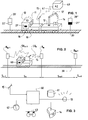
- FIG. 2 schematically illustrates a system which can be used to carry out the inventive method.
- a rail vehicle 10 is shown, but this time for simplicity consisting of a single car.
- FIG. 2 are shown along the rails 30 several S / Es B m-1 , B m , B m + 1 shown.
- the number of S / Es B m-1 , B m , B m + 1 is of course not to be construed limiting, and may be smaller or larger as needed.
- the rail side-S / Es are installed at regular spatial distances.
- the rail side-S / Es which are closer to a warning sector boundary, are arranged closer to each other than the S / Es, which are arranged in the middle of a warning sector. A more precise distance measurement is then possible, especially in those regions where it is most important, namely near the warning sector boundaries.
- At least one of the transmission devices B m-1 , B m , B m + 1 transmits the identifier information assigned to it.
- This information may comprise various data, for example an ID number, which is uniquely associated with a particular transmitter B m-1 , B m , B m + 1 .
- position information (for example, coordinate point data or the like) is sent out from the transmitting devices B m-1 , B m , B m + 1 .
- each of the transmission devices B m-1 , B m , B m + 1 can advantageously use its own communication channel 50 m-1 , 50 m , 50 m + 1 .
- These different communication channels may differ from each other for example by the transmission frequency, coding or another size.
- the different transmitting devices B m-1, B m, B m + 1 one or more communication channels 50 m-1, 50 m, 50 m + share. 1
- the transmitting devices B m-1 , B m , B m + 1 are also arranged so that they are located at the boundaries of the warning areas or sectors S n-1 , S n , S n + 1 .
- the transmitting devices B m-1 , B m , B m + 1 can also be integrated into the above-described warning range limit panels 20 ', 20 ", but clearly other solutions are possible, but which do not deviate from the basic idea of this invention.
- the identification information transmitted by the individual transmission devices B m-1 , B m , B m + 1 is received by a receiving device 15 assigned to the rail vehicle 10.
- the receiving device 15 can in particular be the same receiving device as that which, as described above, is used to receive the warning signals emitted by the alarm center. Of course, it can be a completely different and separate device. Here, for simplicity, a single receiving device 15 is shown, which, however, combines the two functionalities.
- the evaluation device 60 After receiving the identification information from one or more transmitting devices B m-1 , B m , B m + 1 they are transmitted from the receiving device 15 to an evaluation device 60 of the rail vehicle 10.
- the construction of the evaluation device 60 of the rail vehicle 10 will be described below with reference to FIG FIG. 3 described in more detail.
- the evaluation device 60 determines the relative position of the rail vehicle 10, ie the warning sector S n-1 , S n , S n + 1 , in which the rail vehicle 10 is currently located. On the basis of this specific relative position of the rail vehicle 10, the warning parameters associated with this relative position of the rail vehicle 10 are then determined by an adjustment module of the evaluation unit 60 and set to activate the warning device 13, 14.
- this determination runs, for example, so that it is determined by the evaluation device 60 based on the received identification information that the rail vehicle 10 is in the warning sector S n-1 .
- the warning parameters for the warning sector S n-1 ie the frequency of the warning signals, the duration of the warning, etc.
- the number and type of warning parameters depend essentially on the type of transmission of the warning signals, or on the operation of the external alarm center 40 from. However, it will be immediately apparent to one skilled in the art how to determine and adjust these warning parameters in each specific case.
- any type of wireless radio technology can be used for this purpose.
- Some examples of such transmission technologies include NFC, Bluetooth, RFID or even ZigBee.
- other transmission technologies are conceivable, such as the ultrasound, infrared or magnetic field transmission.
- a person skilled in the art will also be able to understand immediately in this case that the choice of a particular transmission technology can not call the basic idea of the invention into question.
- the identification information they can be transmitted uninterruptedly by the transmission devices B m-1 , B m , B m + 1, for example.
- the rail vehicle 10 could receive and evaluate this identification information in this case immediately after entering the corresponding warning sector S n-1 , S n , S n + 1 .
- the identification information may be sent by the individual transmission devices B m-1 , B m , B m + 1 only periodically. In this case, the reception can not happen immediately, but the Radiation quantities are significantly reduced at the construction site.
- an asymmetric transmission pattern can be used by the individual transmission devices B m-1 , B m , B m + 1 send out their identification information with some time delay.
- the frequency spectrum can be much better utilized, and on the other hand, the time information can also be used to improve the positioning quality.
- an activation device associated with the rail vehicle 10 (again shown here for simplicity by the receiving device 15) can be provided, which can send transmission requests to one or more transmission devices B m-1 , B m , B m + 1 as required. It may then be provided that the identification information associated with the transmission devices B m-1 , B m , B m + 1 is transmitted only after the reception of such a transmission request. In this way, additionally the power consumption of the transmitting devices B m-1 , B m , B m + 1 can be reduced.
- reference numeral 61 refers to a database.
- the database 61 may store data for determining the relative position of the rail vehicle 10 and / or the data for determining the warning parameters.
- these data can also contain a list of the identification information associated with each transmission device B m-1 , B m , B m + 1 and / or the warning parameter associated with each warning sector S n-1 , S n , S n + 1 .
- the determination and setting of the warning parameters is such that the received identification information is compared with the identification information stored in the database 61. If there is a match, the corresponding relative position (ie the warning sector) is determined, and then the corresponding warning parameters are read from the database 61 and set.
- identification information of at least two or three different transmission devices B m-1 , B m , B m + 1 is always received and evaluated have to.
- geographical maps or similar information can be stored, based on which the plausibility analysis can be performed. It is also conceivable to carry out the motion analysis in order to exploit the fact that rail vehicles 10 are rail-bound (for example, a rail vehicle 10 can not skip warning sectors).
- other devices can be used to optimize the relative position determination.
- Reference numeral 62 refers to a tachometer and reference numeral 63 to an odometer. By means of these instruments further data (eg speed of the rail vehicle 10, or the distance traveled by it) can be detected, based on which the relative position of the rail vehicle 10 can be used in addition to the received identification information.
- the plausibility analysis of the position determination can also be improved by also measuring and / or calculating the distance between the transmitters and the receiver.
- This distance measurement can be done by means of the transmission field strength (eg the so-called RSSI - Received Signal Strength Indication in English). Otherwise, the calculation of the distance measurement in a known manner based on the signal transit time between transmitter units and receiver.
- the position of a rail vehicle was calculated only occasionally, at locations where the information was present, and where the receiver unit was sensing a signal from a transmitter unit (or transponder).
- the distance measurement and the corresponding identification reading of one or more rail side units may be continuous or on demand, regardless of where the rail vehicle is located.
- this property is the transmission field strength (RSSI), although other possibilities such as signal propagation time measurement could replace the RSSI.
- RSSI transmission field strength
- the evaluation and transmission of such additional information as the RSSI field strength or the distance measurement is important because the switching of the sectors requires a very high accuracy.
- the field strength can also be measured in both directions, ie from the rail vehicle to the power-side S / E or vice versa. It is also conceivable that the field strength is measured in both directions.
- the S / E mounted on the rail vehicle emits a call signal, which is measured by the S / Es arranged on the track side, and is sent back as a measured value in a response signal.
- the evaluation of the field strength can of course also be done on the rail vehicle.
- the S / Es form a network, comparable to a GSM network, in which the evaluation unit is a subscriber, so that all information is sent to this evaluation unit.
- the distances between the rail vehicle and the various rail side S / E are relatively small.
- This approach also takes into account the case when the signals are attenuated (by snow, fog, rain, or any physical obstacles), or when the distance between rail vehicle and rail side is variable or unknown (for example, if there is a greater distance because of Rail vehicle on a further remote track drives), then the signal is already weakened by the successive rail side units accordingly.
- This effect is in the figure 4 represented, where the different rail sides S / Es B m-1 to B m + 3 to a different extent, from the track G 1 are discontinued.
- the system of the invention is also used in tunnels.
- the S / Es can not be set up very far from the track by nature. Also, as a result of reflections situationally different ranges can be achieved. For this reason, the S / Es in tunnels are preferably set up with a slightly lower field strength.
- the evaluation of the relative distance by the calculation of the waveform of the transmission field strength (signal strength), and not its absolute values.
- the evaluation unit which may be implemented, for example, as a programmable logic controller or the like, may be programmed to provide the mathematical features in the time course, such as a time-based curve. calculates any maxima, minima, change of sign in the derivative, etc., to infer an exact distance value.
- This evaluation of the mathematical features in the time curve can also be used to provide information about the time changes (eg acceleration, direction of travel relative to the transceiver) of the rail vehicle, or to allow additional plausibility of the data.
- the transceivers can also be arranged in pairs on the rail side (or even on the rail vehicle).
- two S / E units are oriented along the track (in the direction of travel of the rail vehicle). These S / E pairs may then receive and / or transmit and / or evaluate data signals containing enough information to evaluate the dynamic (time-varying) characteristics of the motion and / or relative position of the rail vehicle.
- the evaluation for switching between one sector and the next usually refers to a specific point along the train.
- the rail side-S / Es are arranged so that the distances of the S / Es are substantially greater than the distance (d2) of the respective S / E orthogonal to the rail vehicle, thereby ensuring that when passing a significant difference between two adjacent S / Es can be measured.
- the transmitting / receiving units are preferably set up such that the transceiver unit (S / E) of the rail vehicle can always communicate with at least one rail side S / E.
- Each transceiver on the track side is assigned a unique identifier.
- the evaluation unit can also recognize the direction of travel of the rail vehicle from the sequence of the exchanged information between the rail vehicle and the transmission side receiving units, and / or any failure or interchange of the service side S / Es, for example due to local network disturbance or vandalism.
- the main purpose of this positioning is to enable the detection of exceeding the warning sector limits. This recognition must be reliable and precise. Thus, for example, if one of the transmitting units fails, detection of a warning sector boundary should not be affected.
- FIG. 5 By way of example, a series of rail side S / Es (eg RFID transceiver units) is shown which extends over two warning sectors (S 234 and S 113 ).
- the rail side-S / Es 234-1 to 234-8 and the rail side-S / Es 113-1 to 113-15 are located in the respective warning sectors S 234 and S 113 .
- the rail side units (234-1, 234-8 / 113-1 and 113-15) denoted S are each located at the warning sector boundaries, and the rail side units designated U are each in transition regions in front of the sector boundaries.
- the essential function of this system is the recognition of the crossing of the sector boundaries, for which reason the evaluation unit of the sector boundaries must be known.
- the transceiver units have a special identifier, or that the evaluation unit knows these transceiver units. Since in a simple failure of a unit, the safety of the system must not be restricted, this failure must be detected. One possibility is to diversify the frontier receiving units.
- the evaluation unit recognizes the transceiver units before and after the boundary. In this way, it is possible to detect the absence of a limit-transmitting unit (for example, in the event of vandalism or any failure of a boundary S / E) and still take into account the sector boundary.
- the rail vehicle is equipped with a reference S / E.
- this reference S / E which is to be similar to the S / Es installed on the rail side, it is possible to check the correct functioning of the S / E mounted on the rail vehicle, if the absence of a service side transmission / Receiving unit is detected. Further, by this reference S / E on the rail vehicle, the transmission / reception unit on the rail vehicle can be adjusted or calibrated.
- the RFID tags can be programmed prior to placement on the rail side by means of a programming device which contains key information (identification information) including data backup (for example by a Cyclic Redundancy Code - CRC). from the conventional ID key.
- the S / It can also be connected to a network (eg a Local Area Network, LAN or a wireless network, WLAN), in which case they can be programmed over the network.
- the radio key ID is always protected by a CRC over the entire communication path ID key - programming device - RFID (S / E) - TAG reader (S / E) - safe programmable logic controller (PLC).
- the entire transmission path can therefore be referred to as a gray channel.
- GPS coordinates are also used when programming the individual S / Es.
- the corresponding GPS coordinates can be programmed. These coordinates are then transmitted to the rail vehicle and used for the evaluation of the position and / or movement of the train.
- the coordinates can also contribute to the plausibility of the position and / or movement information.
- other coordinates can be used which the evaluation device understands.
- the moving rail vehicle may also carry a reference tag of known identifier and position to check the function of the system at all times.
- the S / Es can be consecutively numbered. The numbering goes, for example, from 1 to n. Die1. and nth S / E are also marked with a special flag that marks the beginning and the end of the sector. For a seamless transition from one sector to the other, the nth S / E of the one sector is also the 1st S / E of the next sector and sends out both identifiers. Thus a single failure of a S / E does not lead to a fault, the failure of a transition S / E must also be detected. This happens, for example, by the 2nd S / E and the n-1. S / E also receive a flag indicating that the next S / E represents a sector boundary.
- the evaluation of the position detection is done for example in a secure programmable logic controller.
- the necessary algorithm calculates from the detected S / Es and their signal strength course (as redundancy) the current position of the rail vehicle relative to the established S / Es.
- S / Es are upgraded on the rail side with two antennas, which antennas are spatially offset from each other along the direction of travel of the rail vehicle, but on the same transmission unit. This makes it possible, with a corresponding, running in the evaluation analysis algorithm to achieve the precise determination of the center of the respective S / E, and therefore a much more accurate distance measurement.
- the signals of two locally offset on the rail vehicle reception systems are compared with each other, for example, determines the direction of travel of the rail vehicle. It also allows the prediction of the signals on the other antenna, and therefore an additional security check, as well as the plausibility of the distance measurements.
- the reception of the transmitted signals, the detection of the corresponding signal strength or signal propagation times, and the evaluation of the relative distance and / or position and / or movement of the rail vehicle can all take place either on the rail vehicle and / or on the rail side. If they are performed on the rail side as well as on the rail vehicle, this results in a better plausibility of the data and their evaluations.
Abstract
Description
Die vorliegende Erfindung betrifft ein Verfahren und ein System zur automatisierten Bestimmung und Einstellung von Warnparametern bei Schienenfahrzeugen. Die vorliegende Erfindung betrifft insbesondere ein Verfahren und ein entsprechendes System zur automatisierten Bestimmung und Einstellung von Warnparametern bei Schienenfahrzeugen, bei welchen mindestens eine Warnvorrichtung des Schienenfahrzeugs basierend auf den Warnparametern aktiviert wird.The present invention relates to a method and a system for the automated determination and adjustment of warning parameters in rail vehicles. In particular, the present invention relates to a method and a corresponding system for automated determination and setting of warning parameters in rail vehicles, in which at least one warning device of the rail vehicle is activated based on the warning parameters.
Sicherheit spielt bei Schienenfahrzeugen eine sehr grosse Rolle. Dies ist insbesondere wahr in den Gegenden, in welchen sich Menschen in der Nähe von Schienen aufhalten. So werden schon seit einiger Zeit insbesondere die Bahnübergänge (d.h. Kreuzungen von Schienen mit Strassen) besonders sorgfältig abgesichert. Auch an den Bahnhöfen werden verschiedene Massnahmen getroffen, um die Sicherheit der sich am Bahnsteig befindenden Menschen zu gewährleisten. Auf der anderen Seite spielt die Sicherheit auch eine extrem wichtige Rolle bei Gleisbau-, Gleisunterhalt- oder Gleisreparaturarbeiten. Dabei werden üblicherweise die so genannten Gleisbauzüge oder Gleisbaukompositionen eingesetzt, welche die für die Arbeit notwendigen Vorrichtungen (wie zum Beispiel Krane, Schweissgeräte, usw.) enthalten, und welche zudem auch Gleisbauarbeiter transportieren können.Safety plays a very important role in rail vehicles. This is particularly true in the areas where people are near rails. For some time now, particularly the level crossings (that is, intersections of rails with roads) have been particularly carefully protected. Also at the stations various measures are taken to ensure the safety of people on the platform. On the other hand, safety also plays an extremely important role in track maintenance, track maintenance or track repair work. Usually, the so-called track construction or track construction compositions are used, which contain the necessary equipment for the work (such as cranes, welding equipment, etc.), and which also can transport track workers.
Oft werden an einem Gleis Arbeiten durchgeführt, ohne dass der Bahnverkehr unterbrochen werden kann. Arbeiten werden teilweise an Gleisen durchgeführt, welche sich in unmittelbarer Nähe von nicht gesperrten Gleisen befinden. In solchen Fällen ist es notwendig, dass Gleisarbeiter vor einem herannahenden Zug effizient und rechtzeitig gewarnt werden. Dazu werden Gleisbauzüge mit Warnmitteln ausgestattet, welche die Gleisbauarbeiter durch akustische oder Lichtsignale (oder eine Kombination davon) über die Gefahr vor einem ankommenden Zug informieren. Üblicherweise kommen in solchen Situationen die so genannten Alarm- oder Warnzentralen zum Einsatz, welche einen Überblick über die Baustelle haben, und welche bei Gefahren entsprechende Warnsignale aussenden. Diese Warnsignale werden dann von den Gleisbauzügen empfangen und über die Warnmittel ausgegeben.Often work is carried out on a track, without the rail traffic can be interrupted. Work is partly carried out on tracks, which are located in the immediate vicinity of unlocked tracks. In such cases, it is necessary to warn railway workers of an approaching train efficiently and in a timely manner. For this purpose, track construction trains are equipped with warning devices, which the track construction workers through to notify you of the hazard of an arriving train, whether it is acoustic or light (or a combination thereof). Usually come in such situations, the so-called alarm or warning centers are used, which have an overview of the construction site, and which emit appropriate warning signals in case of danger. These warning signals are then received by the track construction trains and output via the warning means.
Allerdings kann eine Alarmzentrale für mehrere Baustellen oder Baustellenabschnitte zuständig sein. Deshalb ist es bei solchen Systemen wesentlich, dass eine Alarmierung der Gleisarbeiter nur dann erfolgt, wenn sich der Gleisbauzug auch tatsächlich in dem Warnbereich befindet, in welchem die empfangenen Warnsignale effektiv wirksam sein sollten. Bei den herkömmlichen Lösungen werden zu diesem Zweck die so genannten Impfschlüssel mit Positionsinformationen verwendet. Diese Impfschlüssel sind eindeutig einem gewissen Warnbereich zugeordnet und müssen beim Betreten des Warnbereichs in die dafür vorgesehene Steckeinrichtung am Gleisbauzug durch einen Gleisbauarbeiter eingeführt werden. Die auf dem Schlüssel gespeicherten Informationen werden dann von der Auswertungseinheit des Zugs verwendet, um die richtigen Warnsignale auszusuchen.However, an alarm center can be responsible for several construction sites or construction site sections. Therefore, it is essential in such systems that an alerting of the track workers only takes place when the track train is actually in the warning area in which the received warning signals should be effectively effective. In the conventional solutions, the so-called vaccination keys with position information are used for this purpose. These vaccination keys are clearly assigned to a certain warning area and must be introduced by a track construction worker when entering the warning area in the designated plug-in device on the track construction train. The information stored on the key is then used by the evaluation unit of the train to select the correct warning signals.
Nun umfasst diese herkömmliche Lösung selbstverständlich ein paar wichtige Nachteile und birgt ein paar hohe Risiken. So müssen die Impfschlüssel nach jeder Positionsänderung des Gleisbauzugs ausgetauscht werden. Dabei muss ein Gleisbauarbeiter den alten Schlüssel herausstecken und wieder an seinen Ablageort bringen, den neuen Schlüssel an seinem Ablageort abholen und dann wieder in die dafür vorgesehene Öffnung einstecken. In der Zeit, in welcher keiner der beiden Schlüssel eingesteckt ist, kann der Gleisbauzug keine Warnsignale korrekt auswerten. Zudem ist ein Gleisbauarbeiter bei solchen Lösungen stets mit dem Austausch der Impfschlüssel beschäftigt. Keine Automatisierung kann also realisiert werden. Es ist auch klar, dass menschliches Versagen nicht ausgeschlossen werden kann, so dass es auch möglich ist, dass durch unsachgemässem Handeln oder einem Operationsfehler inkorrekte Warnsignalauswertungen stattfinden, was fatale Folgen haben kann.Of course, this conventional solution includes a few important drawbacks and carries a few high risks. So the vaccination must be replaced after each change in position of the track construction. In this case, a track construction worker must remove the old key and bring it back to its storage location, pick up the new key at its storage location and then insert it again into the opening provided for this purpose. In the time in which neither of the two keys is plugged in, the track construction train can evaluate no warning signals correctly. In addition, a track construction worker is always busy with such solutions with the replacement of the vaccination key. No automation can be realized. It is also clear that human error can not be ruled out, so that it is also possible that improper warning signal evaluations take place through improper action or an operational error, which can have fatal consequences.
Es ist auch bekannt, die Position eines Schienenfahrzeuges automatisch auszuwerten. Die US-Patentanmeldung
Es ist daher eine Aufgabe der vorliegenden Erfindung, ein neues Verfahren zur automatisierten Bestimmung und Einstellung von Warnparametern bei Schienenfahrzeugen und ein entsprechendes neues System vorzuschlagen, welche nicht die Nachteile des Standes der Technik aufweisen. Dabei ist es insbesondere eine Aufgabe der vorliegenden Erfindung, ein Verfahren zur automatisierten Bestimmung und Einstellung von Warnparametern bei Schienenfahrzeugen und ein entsprechendes System bereitzustellen, welche jederzeit eine präzise, einfache und sichere vollständig automatisierte Einstellung von Warnparametern bei Schienenfahrzeugen ohne menschlichen Einfluss ermöglichen.It is therefore an object of the present invention to propose a new method for automated determination and adjustment of warning parameters in rail vehicles and a corresponding new system, which do not have the disadvantages of the prior art. In particular, it is an object of the present invention to provide a method for automated determination and adjustment of warning parameters in rail vehicles and a corresponding system, which at any time allow a precise, simple and secure fully automated setting of warning parameters on rail vehicles without human influence.
Gemäss der vorliegenden Erfindung werden diese Ziele vor allem durch die Elemente der beiden unabhängigen Ansprüche erreicht. Weitere vorteilhafte Ausführungsformen gehen ausserdem aus den abhängigen Ansprüchen und der Beschreibung hervor.According to the present invention, these objects are achieved above all by the elements of the two independent claims. Further advantageous embodiments are also evident from the dependent claims and the description.
Insbesondere werden die Ziele der Erfindung dadurch erreicht, dass in einem Verfahren zur automatisierten Bestimmung und Einstellung von Warnparametern bei Schienenfahrzeugen, wobei mindestens eine Warnvorrichtung des Schienenfahrzeugs basierend auf den Warnparametern aktiviert wird, von mindestens einer Sendeeinrichtung mindestens eine der Sendeeinrichtung zugeordnete Kennungsinformation gesendet wird, die mindestens eine Kennungsinformation von einer dem Schienenfahrzeug zugeordneten Empfangseinrichtung empfangen und an eine Auswertungseinrichtung übertragen wird, basierend auf der mindestens einen empfangenen Kennungsinformation die relative (d.h. relative zur Schienenumgebung, oder zu einer bestimmten Schienenseite- Sende-Empfangseinrichtung) Position des Schienenfahrzeugs von der Auswertungseinrichtung bestimmt wird, und die der relativen Position des Schienenfahrzeugs zugeordneten Warnparameter bestimmt und zur Aktivierung der Warnvorrichtung eingestellt werden. Der Vorteil dieser Erfindung liegt vor allem darin, dass die Bestimmung und Einstellung von Warnparametern bei Schienenfahrzeugen auf eine vollkommen automatisierte Art und Weise geschehen kann, ohne Bedarf an menschlichen Operateuren. Dadurch kann der Übergang zwischen den einzelnen Warnbereichen (bei welchem auch die Warnparameter ändern) wesentlich schneller durchgeführt werden. Zudem können eventuelle Betriebsfehler, welche durch unsachgemässe Benutzung oder menschliches Versagen entstehen, vollkommen eliminiert werden, so dass ein höheres Mass an Sicherheit erreicht wird. Schliesslich erlaubt eine solche Lösung eine sehr einfache Konfigurationsänderung oder -korrektur, da lediglich die Kennungsinformationen der einzelnen Sendeeinrichtungen angepasst werden müssen.In particular, the objects of the invention are achieved in that in a method for the automated determination and setting of warning parameters in rail vehicles, wherein at least one warning device of the rail vehicle is activated on the basis of the warning parameters, at least one transmission device sends at least one identification device associated with the transmission device which receives at least one identification information from a receiving device assigned to the rail vehicle and transmits it to an evaluation device based on the at least one received identification information. ie relative to the rail environment, or to a particular rail side transceiver) position of the rail vehicle is determined by the evaluation device, and the relative position of the rail vehicle associated warning parameters determined and set to activate the warning device. The advantage of this invention lies in the fact that the determination and adjustment of warning parameters in rail vehicles can be done in a completely automated manner, without need for human operators. As a result, the transition between the individual warning areas (in which the warning parameters also change) can be carried out much faster. In addition, any operational errors that result from improper use or human error can be completely eliminated, so that a higher level of security is achieved. Finally, such a solution allows a very simple configuration change or correction, since only the identification information of the individual transmitting devices must be adjusted.
In einer Ausführungsvariante wird, zusätzlich zu der mindestens einen empfangenen Kennungsinformation, die relative Position des Schienenfahrzeugs basierend auf von einem Tachometer und/oder einem Odometer erfassten Daten bestimmt. Diese Ausführungsvariante hat insbesondere den Vorteil, dass zusätzlich zu den empfangenen Kennungsinformationen auch eine oder mehrere weitere Positionsdatenquellen verwendet werden. Dadurch kann einerseits die Genauigkeit der Positionswerte wesentlich erhöht werden, und andererseits kann auch die Plausibilität von drahtlos empfangenen Signalen nach Bedarf geprüft werden.In one embodiment variant, in addition to the at least one received identification information, the relative position of the rail vehicle is determined based on data acquired by a tachometer and / or an odometer. This embodiment variant has the particular advantage that in addition to the received identification information also one or more further position data sources are used. As a result, on the one hand, the accuracy of the position values can be substantially increased, and on the other hand, the plausibility of wirelessly received signals can also be checked as required.
In einer anderen Ausführungsvariante wird die der mindestens einen Sendeeinrichtung zugeordnete Kennungsinformation periodisch von der Sendeeinrichtung gesendet. Diese Ausführungsvariante hat insbesondere den Vorteil, dass der Kommunikationskanal durch die Sendeeinrichtung nur kurz belegt wird und Mehrfachbelegungen von mehreren Sendeeinrichtungen auf demselben Kommunikationskanal möglich werden. Ausserdem kann auf der anderen Seite durch einen periodischen Empfang der Kennungsinformation die Kontrolle der Funktionstüchtigkeit der Sendeeinrichtungen ohne einen grossen zusätzlichen Aufwand vollzogen werden.In another embodiment variant, the identification information associated with the at least one transmission device is transmitted periodically by the transmission device. This embodiment variant has the particular advantage that the communication channel is occupied only briefly by the transmitting device and multiple assignments of several transmitting devices on the same communication channel are possible. In addition, on the other hand, by periodically receiving the identification information, it is possible to control the functionality of the transmission devices without a great deal of additional effort.
In einer alternativen Ausführungsvariante wird von einer dem Schienenfahrzeug zugeordneten Aktivierungseinrichtung eine Sendeaufforderung gesendet und von mindestens einer Sendeeinrichtung empfangen, und dann die mindestens eine der Sendeeinrichtung (Bm-1, Bm, Bm+1) zugeordnete Kennungsinformation von mindestens einer Sendeeinrichtung gesendet. Der Vorteil dieser Ausführungsvariante liegt insbesondere darin, dass die Sendeeinrichtungen im Normalfall inaktiv bzw. passiv sind. Die Kennungsinformation wird in diesem Fall nur dann ausgesendet, wenn eine Sendeaufforderung seitens der Aktivierungseinrichtung des Schienenfahrzeugs von einer Sendeeinrichtung empfangen wird. Dadurch kann der Stromverbrauch der Sendeeinrichtungen wesentlich reduziert werden, und es können auch überlappende Warnabschnitte entflechtet werden. Zudem kann dadurch die Strahlungsmenge in der Umgebung der Sendeeinrichtungen über eine gewisse Zeitspanne reduziert werden, was einerseits die Störungen und Interferenzen zwischen den von verschiedenen Sendeeinrichtungen ausgesendeten Signalen, und andererseits das Gesundheitsrisiko für die sich in der Umgebung befindenden Menschen (zum Beispiel Gleisbauarbeiter) vermindern kann.In an alternative embodiment variant, a transmission request is sent from an activation device assigned to the rail vehicle and received by at least one transmission device, and then the identification information associated with at least one transmission device (B m-1 , B m , B m + 1 ) is transmitted by at least one transmission device. The advantage of this embodiment lies in the fact that the transmitting devices are normally inactive or passive. The identification information is transmitted in this case only when a transmission request is received by the transmitting device of the rail vehicle from a transmitting device. As a result, the power consumption of the transmitting devices can be substantially reduced, and also overlapping warning sections can be unbundled. In addition, this can reduce the amount of radiation in the vicinity of the transmitting devices over a certain period of time, which on the one hand can reduce the interference and interference between the signals emitted by different transmitting devices and, on the other hand, the health risk to the people in the vicinity (for example track construction workers) ,
In einer anderen Ausführungsvariante wird mit der der Sendeeinrichtung zugeordneten Kennungsinformation mindestens eine eindeutige Positionsidentifikation der Sendeeinrichtung gesendet. Der Vorteil dieser Ausführungsvariante liegt insbesondere darin, dass zusätzliche Funktionen des Systems ausgenutzt werden können. Insbesondere kann die Auswertung solcher Kennungsidentifikationen relativ schnell und einfach durchgeführt werden.In another embodiment variant, at least one unique position identification of the transmitting device is transmitted with the identification information assigned to the transmitting device. The advantage of this variant is in particular that additional functions of the system can be utilized. In particular, the Evaluation of such identifier identifications are relatively quickly and easily performed.
In einer weiteren Ausführungsvariante werden zur Bestimmung der relativen Position des Schienenfahrzeugs und/oder zur Bestimmung der Warnparameter die in einer Datenbank gespeicherten Daten verwendet. Diese Ausführungsvariante hat insbesondere den Vorteil, dass die relative Positionsbestimmung bei komplexen Umgebungen mit mehrfach überlappenden Sendebereichen mit unterschiedlichen Kennungsinformationen möglich ist. Zudem kann die Positionsbestimmung auch besonders einfach realisiert werden, indem die empfangenen Daten mit den in der Datenbank gespeicherten Daten verglichen wird. Die gespeicherten Daten können nach Bedarf auch Karteninformationen enthalten, welche zur einfachen Signalauswertung und Parameterbestimmung eingesetzt werden können.In a further embodiment variant, the data stored in a database are used to determine the relative position of the rail vehicle and / or to determine the warning parameters. This embodiment variant has the particular advantage that the relative position determination in complex environments with multiple overlapping transmission ranges with different identification information is possible. In addition, the position determination can also be implemented particularly easily by comparing the received data with the data stored in the database. The stored data can also contain map information as needed, which can be used for simple signal evaluation and parameter determination.
In einer wieder weiteren Ausführungsvariante wird die der Sendeeinrichtung zugeordnete Kennungsinformation von jeder Sendeeinrichtung über einen eigenen Kommunikationskanal gesendet. Diese Ausführungsvariante hat insbesondere den Vorteil, dass gleichzeitig mehrere Sendeeinrichtungen empfangen und ausgewertet werden können, ohne dass es durch ein Durcheinandersenden zu Störungen oder Interferenzen kommen könnte. Zudem kann ein Kommunikationskanal beispielsweise eineindeutig einer bestimmten Sendeeinrichtung zugeordnet werden, so dass die Empfangseinrichtung gezielt auf diesen Kanal eingestellt werden kann, um die gewünschte Kennungsinformation zu erhalten.In a further embodiment, the identification information associated with the transmission device is transmitted by each transmission device via its own communication channel. This embodiment variant has the particular advantage that several transmitting devices can be received and evaluated at the same time, without interference or interference occurring as a result of confusion. In addition, a communication channel can for example be unambiguously assigned to a specific transmitting device, so that the receiving device can be set specifically to this channel in order to obtain the desired identification information.
In einer anderen Ausführungsvariante wird nach der Bestimmung und Einstellung der Warnparameter eine Warninformation der Alarmzentrale von der Empfangseinrichtung empfangen, und basierend auf den empfangenen Warnparametern die mindestens eine Warnvorrichtung des Schienenfahrzeugs von der Auswertungseinrichtung aktiviert. Der Vorteil dieser Ausführungsvariante liegt insbesondere darin, dass die Warnausgabe zeitlich und örtlich stets mit der Warninformation der Alarmzentrale übereinstimmt. Dabei wird die Einstellung der Warnparameter vollkommen automatisiert durchgeführt, so dass kein zusätzlicher Aufwand entsteht.In another embodiment variant, after the determination and setting of the warning parameters, warning information of the alarm center is received by the receiving device, and the at least one warning device of the rail vehicle is activated by the evaluation device based on the received warning parameters. The advantage of this embodiment lies in particular in the fact that the warning output always coincides in time and location with the warning information of the alarm center. The setting of the warning parameters is carried out completely automatically, so that no additional expense arises.
In einer weiteren Ausführungsvariante werden empfangene Daten und/oder Logdaten von der Auswertungseinrichtung in die Datenbank gespeichert. Diese Ausführungsvariante hat insbesondere den Vorteil, dass der gesamte Ablauf der Datenübertragung festgehalten werden kann. Dadurch können insbesondere alle normalen und speziellen Abläufe sowie auch spezielle Vorfälle nachträglich belegt und ausgewertet werden.In a further embodiment, received data and / or log data are stored by the evaluation device in the database. This embodiment variant has the particular advantage that the entire process of data transmission can be recorded. As a result, in particular all normal and special processes as well as special incidents can be subsequently assigned and evaluated.
An dieser Stelle soll festgehalten werden, dass sich die vorliegende Erfindung neben dem erfindungsgemässen Verfahren auch auf ein entsprechendes System zur automatisierten Bestimmung und Einstellung von Warnparametern bei Schienenfahrzeugen bezieht.It should be noted at this point that, in addition to the method according to the invention, the present invention also relates to a corresponding system for the automated determination and setting of warning parameters in rail vehicles.
Dabei kann in dem System die der mindestens einer Sendeeinrichtung zugeordnete Kennungsinformation über ein drahtloses Funknetz sendbar und empfangbar sein. Das drahtlose Funknetz kann dabei beispielsweise ein NFC- und/oder Bluetooth- und/oder RFID- und/oder ZigBee-Netz sein. Diese aber auch andere Technologien zur Datenübertragung können verwendet werden, um eine sichere und funktionstüchtige Lösung zu realisieren.In this case, in the system, the identification information associated with the at least one transmission device can be sendable and receivable via a wireless radio network. The wireless radio network can be, for example, an NFC and / or Bluetooth and / or RFID and / or ZigBee network. However, these other data transmission technologies can also be used to create a secure and functional solution.
In dieser Anmeldung wird beispielhaft eine Ausführungsvariante der Erfindung beschrieben, in welcher eine auf dem Schienenfahzeug montierte Empfangseinheit ein Signal von mehreren auf der Schienenseite installierten Sendeeinheiten empfängt. Erfindungsgemäss kann aber die auf dem Schienenfahrzeug montierte Einheit sowohl eine Sende- als auch eine Empfangsfunktion haben. Ebenfalls die auf der Schienenseite installierten Sendeeinheiten können auch eine Empfangsfunktion aufweisen. Wichtig ist, dass die Kommunikation zwischen Schienenfahrzeug und Schienenseite stattfindet. Die Richtung dieser Kommunikation spielt eine untergesetzte Rolle. Deshalb sind die verschiedenen Einheiten in diesem Text als Sende/Empfangseinheiten (S/E) bezeichnet - wo nicht anderes präzisiert ist, ist unter dem Begriff Sende/Empfangseinrichtung (S/E) eine Einheit, die eine Sendefunktion und/oder eine Empfangsfunktion hat, zu verstehen.In this application, an embodiment variant of the invention is described by way of example, in which a receiving unit mounted on the rail vehicle receives a signal from a plurality of transmission units installed on the rail side. According to the invention, however, the unit mounted on the rail vehicle can have both a transmitting and a receiving function. Likewise, the transmission units installed on the rail side can also have a reception function. It is important that the communication between rail vehicle and rail side takes place. The direction of this communication plays a subordinate role. Therefore, the various units in this text are referred to as transceiver units (S / E) - unless otherwise specified, the term transceiver (S / E) is a unit having a transmit function and / or a receive function, to understand.
In einer weiteren Ausführungsvariante der Erfindung ist die Kommunikation zwischen Schienenfahrzeug und Schienenseite kontinuierlich, mit dem Ergebnis, dass eine präzise, aktuelle Auswertung der relativen Position des Schienenfahrzeuges jederzeit stattfinden kann. In einer anderen Ausführungsvariante findet die Kommunikation zwischen Schienenfahzeug und Schienenseite nur bei Bedarf statt. Die auf dem Schienenfahrzeug montierte S/E kann zum Beispiel so eingerichtet werden, dass sie in zeitlichen Abständen (alle 20 Sekunden, zum Beispiel) ein Anfragesignal sendet, worauf die auf der Schienenseite montierten S/Es mit Ihren Kennungs- und zusätzlichen Daten reagieren. Diese zusätzliche Daten können zum Beispiel Informationen zur RSSI-Feldstärke des ausgestrahlten Signals enthalten, wie das Signal an die jeweiligen S/E empfangen wurde, oder gar eine von dieser RSSI-Feldstärke ausgerechnete, relative Distanzmessung.In a further embodiment of the invention, the communication between rail vehicle and rail side is continuous, with the result that a precise, current evaluation of the relative position of the rail vehicle can take place at any time. In another embodiment, the communication between rail vehicle and rail side takes place only when needed. For example, the S / E mounted on the rail vehicle can be set up to send a request signal at intervals (every 20 seconds, for example), whereupon the S / Es mounted on the rail side react with their identification and additional data. This additional data may include, for example, information about the RSSI field strength of the radiated signal, how the signal was received at the respective S / E, or even a relative distance measurement calculated from this RSSI field strength.
Die Auswertung der Daten kann also auf dem Schienenfahrzeug stattfinden, oder auf der Schienenseite. Wesentlich für die Erfindung ist es, dass das Schienenfahrzeug die Information zu seiner Position empfängt, die ihm erlaubt, die dem Warnsektor entspechenden Warnsignale zu unterscheiden.The evaluation of the data can therefore take place on the rail vehicle, or on the rail side. Essential to the invention is that the rail vehicle receives the information about its position, which allows it to distinguish the warning sector entspechenden warning signals.
Nachfolgend werden die Ausführungsvarianten der vorliegenden Erfindung anhand von Beispielen beschrieben. Die Beispiele der Ausführungen werden durch folgende beigelegte Figuren illustriert:
-
Figur 1 -
Figur 2 -
Figur 3 zeigt schematisch die Auswertungseinheit und die mit dieser Auswertungseinheit verbundenen Elemente im System zur automatisierten Bestimmung und Einstellung der Warnparameter bei Schienenfahrzeugen gemäss einer Ausführungsvariante der vorliegenden Erfindung. -
Figur 4 zeigt schematisch, wie die Distanzen zwischen dem Schienenfahrzeug und den S/Es auf der Schienenseite variabel sein können. -
Figur 5 zeigt schematisch die Bezeichnung zweier Reihen von S/Es in zwei entsprechnden Warnsektoren sowie die Bezeichnung der in der Sektorgrenzen und die S/Es in der Nähe der Sektorgrenzen.
-
FIG. 1 shows a perspective schematic representation of a rail vehicle in a corresponding environment, wherein the adjustment of the warning parameters is carried out by means of a conventional method of the prior art. -
FIG. 2 shows a perspective schematic representation of the system and the method for automated determination and adjustment the warning parameter in rail vehicles according to an embodiment of the present invention. -
FIG. 3 schematically shows the evaluation unit and associated with this evaluation unit elements in the system for automated determination and adjustment of the warning parameters in rail vehicles according to an embodiment of the present invention. -
FIG. 4 schematically shows how the distances between the rail vehicle and the S / Es can be variable on the rail side. -
FIG. 5 shows schematically the designation of two rows of S / Es in two corresponding warning sectors as well as the designation of the sector boundaries and the S / Es near the sector boundaries.
In
Das Schienenfahrzeug 10 in
Bei der Auswertung der empfangenen Warnsignale spielt die Position des Schienenfahrzeugs 10 eine entscheidende Rolle. So macht es keinen Sinn, Warnsignale zu übernehmen und Warnmittel 13, 14 zu betätigen, wenn sich die Warnung auf einen anderen Baustellenbereich beziehen. Deshalb ist die Positionsinformation ein wesentliches Element in der Auswertung der empfangenen Warnsignale. Im herkömmlichen System gemäss Stand der Technik wird die Positionsinformation über die so genannten Impfschlüssel 21', 21" an das Schienenfahrzeug 10 übertragen. Üblicherweise hangen diese Impfschlüssel 21', 21 "an den so genannten Warnsektorgrenztafeln 20', 20", wobei dafür spezielle Aufnahmen 22', 22" vorgesehen werden können. Beim Eintreten des Schienenfahrzeugs 10 in den Warnsektor, welcher durch die beiden Grenztafeln 20' und 20" begrenzt ist, muss der entsprechende Impfschlüssel 21' durch einen Gleisbauarbeiter von der Grenztafel 20' entnommen und in die dafür vorgesehene Stecköffnung 16 am Schienenfahrzeug 10 eingesteckt werden. Im Steckschlüssel 21' sind die Positionsinformationen gespeichert, aufgrund welcher die Auswertung der empfangenen Warnsignale dann korrekt durchgeführt werden kann.When evaluating the received warning signals, the position of the
Nach dem Verlassen des Warnsektors, welcher sich zwischen den Warnbereichgrenztafeln 20' und 20" befindet, muss der Impfschlüssel 21' wieder aus der Stecköffnung 16 am Schienenfahrzeug 10 entnommen und in die Aufnahme 22' an der Grenztafel 20' zurück gebracht werden. Ausserdem muss ein neuer Impfschlüssel (entsprechend der neuen Position) wieder von seiner Tafel genommen und in der Stecköffnung 16 untergebracht werden, damit die Auswertung der empfangenen Signale reibungslos verlaufen kann.After leaving the warning sector, which is located between the warning
Erfindungsgemäss werden jedoch die Positionsbestimmung und damit auch die entsprechende Bestimmung und die Einstellung von Warnparametern bei Schienenfahrzeugen 10 automatisiert vorgenommen, so dass insbesondere auch die Aktivierung der Warnvorrichtungen 13, 14 automatisiert werden kann.According to the invention, however, the position determination and thus also the corresponding determination and the setting of warning parameters in
In
Mindestens eine der Sendeeinrichtung Bm-1, Bm, Bm+1 sendet die ihr zugeordnete Kennungsinformation aus. Diese Information kann verschiedene Daten umfassen, beispielsweise eine ID-Nummer, welche eineindeutig einer bestimmten Sendeeinrichtung Bm-1, Bm, Bm+1 zugeordnet ist. Zudem können auch Positionsinformationen (zum Beispiel Koordinatenpunktdaten oder Ähnliches) von den Sendeeinrichtungen Bm-1, Bm, Bm+1 ausgesendet werden. Zur Ausstrahlung der Kennungsinformationen kann jede der Sendeeinrichtungen Bm-1, Bm, Bm+1 vorteilhaft einen eigenen Kommunikationskanal 50m-1, 50m, 50m+1 verwenden. Diese unterschiedlichen Kommunikationskanäle können sich beispielsweise durch die Sendefrequenz, Kodierung oder eine andere Grösse voneinander unterscheiden. Selbstverständlich ist jedoch ebenfalls möglich, dass sich die verschiedenen Sendeeinrichtungen Bm-1, Bm, Bm+1 einen oder mehrere Kommunikationskanäle 50m-1, 50m, 50m+1 teilen. Grundsätzlich werden die Sendeeinrichtungen Bm-1, Bm, Bm+1 auch so angeordnet, dass sie sich an den Grenzen der Warnbereiche bzw. -sektore Sn-1, Sn, Sn+1 befinden. Insbesondere können die Sendeeinrichtungen Bm-1, Bm, Bm+1 auch in die oben beschriebenen Warnbereichgrenztafeln 20', 20" integriert werden. Klar sind aber auch andere Lösungen möglich, welche jedoch nicht vom Grundgedanken dieser Erfindung abweichen.At least one of the transmission devices B m-1 , B m , B m + 1 transmits the identifier information assigned to it. This information may comprise various data, for example an ID number, which is uniquely associated with a particular transmitter B m-1 , B m , B m + 1 . In addition, you can Also, position information (for example, coordinate point data or the like) is sent out from the transmitting devices B m-1 , B m , B m + 1 . For the purpose of transmitting the identification information, each of the transmission devices B m-1 , B m , B m + 1 can advantageously use its own communication channel 50 m-1 , 50 m , 50 m + 1 . These different communication channels may differ from each other for example by the transmission frequency, coding or another size. Naturally, however, is also possible that the different transmitting devices B m-1, B m, B m + 1 one or more communication channels 50 m-1, 50 m, 50 m + share. 1 In principle, the transmitting devices B m-1 , B m , B m + 1 are also arranged so that they are located at the boundaries of the warning areas or sectors S n-1 , S n , S n + 1 . In particular, the transmitting devices B m-1 , B m , B m + 1 can also be integrated into the above-described warning
Die von den einzelnen Sendeeinrichtungen Bm-1, Bm, Bm+1 ausgesendeten Kennungsinformationen werden von einer dem Schienenfahrzeug 10 zugeordneten Empfangseinrichtung 15 empfangen. Die Empfangseinrichtung 15 kann insbesondere dieselbe Empfangseinrichtung sein, wie diejenige, welche, wie oben beschrieben, zum Empfang der von der Alarmzentrale ausgesendeten Warnsignale verwendet wird. Selbstverständlich kann es sich aber dabei um eine vollkommen unterschiedliche und separate Einrichtung handeln. Hier wird zur Einfachheit eine einzige Empfangseinrichtung 15 dargestellt, welche jedoch die beiden Funktionalitäten vereint.The identification information transmitted by the individual transmission devices B m-1 , B m , B m + 1 is received by a receiving
Nach dem Empfang der Kennungsinformation von einer oder mehreren Sendeeinrichtungen Bm-1, Bm, Bm+1 werden sie von der Empfangseinrichtung 15 an eine Auswertungseinrichtung 60 des Schienenfahrzeugs 10 übertragen. Der Aufbau der Auswertungseinrichtung 60 des Schienenfahrzeugs 10 wird weiter unten mit Bezug auf
Zur Übertragung der Kennungsinformationen der Sendeeinrichtungen Bm-1, Bm, Bm+1 eignen sich viele verschiedene Übertragungstechnologien. So können insbesondere jegliche Arten von drahtlosen Funktechnologien (analoger und digitaler Funk) zu diesem Zweck eingesetzt werden. Einige Beispiele solcher Übertragungstechnologien umfassen NFC, Bluetooth, RFID oder auch ZigBee. Andererseits sind auch andere Übertragungstechnologien denkbar, so auch beispielsweise die Ultraschall-, Infrarot- oder Magnetfeldübertragung. Ein Fachmann wird aber auch in diesem Fall unmittelbar verstehen können, dass die Wahl einer bestimmten Übertragungstechnologie nicht die Grundidee der Erfindung in Frage stellen kann. Bei der Übertragung der Kennungsinformationen können sie von den Sendeeinrichtungen Bm-1, Bm, Bm+1 beispielsweise ununterbrochen gesendet werden. Das Schienenfahrzeug 10 könnte diese Kennungsinformationen in diesem Fall sofort nach dem Eintritt in den entsprechenden Warnsektor Sn-1, Sn, Sn+1 empfangen und auswerten. Andererseits kann es vorteilhaft sein, dass die Kennungsinformationen von den einzelnen Sendeeinrichtungen Bm-1, Bm, Bm+1 nur periodisch gesendet werden. In diesem Fall kann der Empfang nicht sofort geschehen, jedoch können die Strahlungsmengen an der Baustelle wesentlich vermindert werden. Auch kann in diesem Fall zum Beispiel ein asymmetrisches Sendemuster verwendet werden, indem die einzelnen Sendeeinrichtungen Bm-1, Bm, Bm+1 ihre Kennungsinformationen etwas zeitversetzt aussenden. So kann einerseits das Frequenzspektrum viel besser ausgenutzt werden, und andererseits kann die Zeitinformation auch zur Verbesserung der Positionsbestimmungsqualität eingesetzt werden. Schliesslich kann auch eine dem Schienenfahrzeug 10 zugeordnete Aktivierungseinrichtung (hier zur Einfachheit erneut durch die Empfangseinrichtung 15 dargestellt) vorgesehen werden, welche nach Bedarf Sendeaufforderungen an eine oder mehrere Sendeeinrichtungen Bm-1, Bm, Bm+1 senden kann. Es kann dann vorgesehen werden, dass die den Sendeeinrichtungen Bm-1, Bm, Bm+1 zugeordnete Kennungsinformation erst nach dem Empfang einer solchen Sendeaufforderung gesendet wird. Auf diese Weise kann zusätzlich auch noch der Stromverbrauch der Sendeeinrichtungen Bm-1, Bm, Bm+1 gesenkt werden.Many different transmission technologies are suitable for transmitting the identification information of the transmission devices B m-1 , B m , B m + 1 . In particular, any type of wireless radio technology (analogue and digital radio) can be used for this purpose. Some examples of such transmission technologies include NFC, Bluetooth, RFID or even ZigBee. On the other hand, other transmission technologies are conceivable, such as the ultrasound, infrared or magnetic field transmission. However, a person skilled in the art will also be able to understand immediately in this case that the choice of a particular transmission technology can not call the basic idea of the invention into question. During the transmission of the identification information, they can be transmitted uninterruptedly by the transmission devices B m-1 , B m , B m + 1, for example. The
In
Zur Verbesserung der Genauigkeit der relativen Positionsbestimmung kann beispielsweise vorgesehen werden, dass immer Kennungsinformationen von mindestens zwei oder drei verschiedenen Sendeeinrichtungen Bm-1, Bm, Bm+1 empfangen und ausgewertet werden müssen. Auch können in der Datenbank 61 auch geografische Karten oder ähnliche Informationen gespeichert werden, aufgrund welcher die Plausibilitätsanalyse durchgeführt werden kann. Auch ist es denkbar, die Bewegungsanalyse durchzuführen, um die Tatsache auszunützen, dass Schienenfahrzeuge 10 schienengebunden sind (so kann ein Schienenfahrzeug 10 beispielsweise Warnsektoren nicht überspringen). Zudem können auch weitere Vorrichtungen verwendet werden, um die relative Positionsbestimmung zu optimieren. In
Die Plausibilitätsanalyse der Positionsbestimmung kann auch verbessert werden, indem auch die Distanz zwischen den Sendern und dem Empfänger gemessen und/oder gerechnet wird. Diese Distanzmessung kann mittels der Sendefeldstärke erfolgen (zB der so genannten RSSI - Received Signal Strength Indication in englischer Sprache). Andernfalls kann die Berechnung der Distanzmessung in bekannter Weise auf die Signallaufzeit zwischen Sendereinheiten und Empfänger basieren. Diese Distanzmessungen, kombiniert mit den Identifikationsdaten der Sendereinheiten, ermöglicht eine wesentlich präzisere Positionsbestimmung, insbesondere wenn die Distanzen und die ID-Daten zweier oder mehrerer S/Es kombiniert werden. Bei den vorherigen Systemen wie etwa in
Zusätzlich zur Information der auf der Schienenseite montierten S/Es wird eine weitere Eigenschaft ausgewertet für die Bestimmung der Distanz zwischen der sendenden SE und der empfangenden S/E.In addition to informing the S / S mounted on the rail side, another property is evaluated for determining the distance between the sending SE and the receiving S / E.
In einer Ausführungsvariante der Erfindung ist diese Eigenschaft die Sendefeldstärke (RSSI), obwohl auch andere Möglichkeiten wie eine Signallaufzeitmessung die RSSI ersetzen könnte. Die Auswertung und Übermittlung solcher Zusatzinformationen wie die RSSI-Feldstärke oder die Distanzmessung ist wichtig, weil die Umschaltung der Sektoren eine sehr hohe Genauigkeit erfordert. Die Messung der Feldstärke kann auch in beide Richtungen erfolgen, das heisst vom Schienenfahrzeug zur geleiseseitigen S/E oder umgekehrt. Es ist auch denkbar, dass die Feldstärke in beide Richtungen gemessen wird. In dieser Ausführungsvariante der Erfindung strahlt die auf dem Schienenfahrzeug montierte S/E ein Aufrufsignal aus, das von den an der Geleiseseite angeordneten S/Es gemessen wird, und als Messwert in einem Antwortsignal wieder zurückgeschickt wird.In one embodiment of the invention, this property is the transmission field strength (RSSI), although other possibilities such as signal propagation time measurement could replace the RSSI. The evaluation and transmission of such additional information as the RSSI field strength or the distance measurement is important because the switching of the sectors requires a very high accuracy. The field strength can also be measured in both directions, ie from the rail vehicle to the power-side S / E or vice versa. It is also conceivable that the field strength is measured in both directions. In this embodiment variant of the invention, the S / E mounted on the rail vehicle emits a call signal, which is measured by the S / Es arranged on the track side, and is sent back as a measured value in a response signal.
Die Auswertung der Feldstärke kann auch natürlich auf dem Schienenfahrzeug geschehen. In einer weiteren Ausführungsvariante der Erfindung bilden die S/Es ein Netzwerk, vergleichbar mit einem GSM Netz, in dem die Auswerteeinheit ein Teilnehmer ist, so dass alle Informationen an diese Auswerteeinheit geschickt werden. Um eine präzise Bestimmung der Position des Schienenfahrzeuges zu berechnen ist es normalerweise nicht nötig, absolute Distanzmessungen zu machen, weil die Messwerte mehrerer S/Es in Betracht gezogen werden. Daher, in einer weiteren Ausführungsvariante der Erfindung, werden die Distanzen zwischen Schienenfahrzeug und den verschiedenen Schienenseite-S/Es lediglig relativ bemessen. Dieses Vorgehen berücksichtigt auch den Fall, wenn die Signale gedämpft sind (durch Schnee, Nebel, Regen, oder durch jegliche physikalische Hindernisse), oder wenn die Distanz zwischen Schienenfahrzeug und Schienenseite variabel oder unbekannt ist (zum Beispiel wenn eine grössere Distanz besteht, weil das Schienenfahrzeug auf einem weiteren entfernten Geleise fährt), dann ist das Signal schon von den aufeinanderfolgenden Schienenseiteeinheiten entsprechend geschwächt. Dieser Effekt ist in der
Das System der Erfindung wird auch in Tunneln benutzt. Dort können die S/Es naturgemäss nicht sehr weit vom Gleise entfernt aufgestellt werden. Auch sind infolge von Reflexionen situativ stark unterschiedliche Reichweiten erreichbar. Aus diesem Grund werden die S/Es in Tunneln vorzugsweise mit einer etwas niedrigeren Feldstärke eingerichtet.The system of the invention is also used in tunnels. There, the S / Es can not be set up very far from the track by nature. Also, as a result of reflections situationally different ranges can be achieved. For this reason, the S / Es in tunnels are preferably set up with a slightly lower field strength.
Vorzugsweise erfolgt die Auswertung der relativen Distanz durch die Berechnung des Kurvenverlaufs der Sendefeldstärke (Signalstärke), und nicht dessen Absolutwerte. Die Auswerteeinheit, die zum Beispiel als speicherprogrammierbares Steuerungsgerät oder dergleichen implementiert werden kann, kann derart programmiert werden, dass sie die mathematischen Merkmale im zeitlichen Kurvenverlauf, wie z.B. jegliche Maxima, Minima, Wechsel des Vorzeichens in der Ableitung usw., ausrechnet, um einen genauen Distanzwert zu inferieren. Diese Auswertung der mathematischen Merkmale im zeitlichen Kurvenverlauf können auch verwendet werden, um eine Information über die zeitliche Änderungen (zB Beschleunigung, Fahrtrichtung relativ zur Sende-Empfangseinrichtung) des Schienenfahrzeugs zu ergeben, oder um eine zusätzliche Plausibilisierung der Daten zu ermöglichen.Preferably, the evaluation of the relative distance by the calculation of the waveform of the transmission field strength (signal strength), and not its absolute values. The evaluation unit, which may be implemented, for example, as a programmable logic controller or the like, may be programmed to provide the mathematical features in the time course, such as a time-based curve. calculates any maxima, minima, change of sign in the derivative, etc., to infer an exact distance value. This evaluation of the mathematical features in the time curve can also be used to provide information about the time changes (eg acceleration, direction of travel relative to the transceiver) of the rail vehicle, or to allow additional plausibility of the data.
Durch die Auswertung des zeitlichen Verlaufs der Signalstärke (RSSI) können mobile und/oder einstweilige Hindernisse (sich temporär zwischen Sender und Empfänger schiebendes Hindernis, wie z.B. ein parallel verlaufender Zug) erkannt und berücksichtigt werden.By evaluating the time course of the signal strength (RSSI), mobile and / or temporary obstacles (obstacles temporarily shifting between transmitter and receiver, such as a parallel train) can be detected and taken into account.
Die Sende-Empfangseinrichtungen können auch paarweise an der Schienenseite (oder gar auf dem Schienenfahrzeug) angeordnet. Vorzugsweise werden zwei S/E Einheiten längs des Geleises (und zwar in der Fahrtrichtung des Schienenfahrzeuges) orientiert. Diese S/E-Paare können dann Datensignale empfangen und/oder übermitteln und/oder auswerten, die genug Informationen enthalten, um die dynamische (zeitlich ändernde) Eigenschaften der Bewegung und/oder der relativen Position des Schienenfahrzeugs auszuwerten.The transceivers can also be arranged in pairs on the rail side (or even on the rail vehicle). Preferably, two S / E units are oriented along the track (in the direction of travel of the rail vehicle). These S / E pairs may then receive and / or transmit and / or evaluate data signals containing enough information to evaluate the dynamic (time-varying) characteristics of the motion and / or relative position of the rail vehicle.
Die Auswertung für die Umschaltung zwischen einem Sektor und dem Nächsten bezieht sich in der Regel auf einen bestimmten Punkt entlang des Zuges. Der minimale Abstand des Zuges zu den Schienenseit-S/Es kann variieren je nach dem, wo die Tags entlang des Geleises montiert werden und je nach dem, wie viele Geleise sich zwischen dem Schienenfahrzeug und den Sende/Empfangsstationen befinden.The evaluation for switching between one sector and the next usually refers to a specific point along the train. The minimum distance of the train to the rail side S / It can vary depending on where the tags are mounted along the track and depending on how many tracks are between the rail vehicle and the transceiver stations.
Vorzugsweise sind die Schienenseite-S/Es so angeordnet, dass die Distanzen der S/Es untereinander (d1) wesentlich grösser sind als der Abstand (d2) des jeweiligen S/E orthogonal zum Schienenfahrzeugg, damit sichergestellt ist, dass beim Vorbeifahren ein deutlicher Unterschied zwischen zwei benachbarten S/Es gemessen werden kann.Preferably, the rail side-S / Es are arranged so that the distances of the S / Es are substantially greater than the distance (d2) of the respective S / E orthogonal to the rail vehicle, thereby ensuring that when passing a significant difference between two adjacent S / Es can be measured.
Geleiseseitig sind die Sende-/ Empfangseinheiten (Schienenseite-S/Es) vorzugsweise so aufgestellt, dass die Sende-Empfangseinheit (S/E) des Schienenfahrzeugs immer mit mindestens einer Schienenseite-S/E kommunizieren kann. Jeder Sende-Empfangseinheit auf der Geleiseseite ist eine eindeutige Kennung zugewiesen. Aus der Reihenfolge der ausgetauschten Informationen zwischen dem Schienenfahrzeug und den geleiseseitigen Sende-Empfangseinheiten kann die Auswerteeinheit auch die Fahrtrichtung des Schienenfahrzeuges erkennen, und/oder jeglichen Ausfall oder Vertauschung der geleiseseitigen S/Es, zum Beispiel durch örtlichen Netzstörung oder Vandalismus.On the jaw side, the transmitting / receiving units (rail side-S / Es) are preferably set up such that the transceiver unit (S / E) of the rail vehicle can always communicate with at least one rail side S / E. Each transceiver on the track side is assigned a unique identifier. The evaluation unit can also recognize the direction of travel of the rail vehicle from the sequence of the exchanged information between the rail vehicle and the transmission side receiving units, and / or any failure or interchange of the service side S / Es, for example due to local network disturbance or vandalism.
Dies kann beispielsweise erreicht werden, indem jede S/E eine eindeutige Nummer hat, welche entlang dem Geleise stetig steigt, oder indem die Reihenfolge der Kennung in der Auswerteeinheit bekannt ist.This can be achieved, for example, by having each S / E a unique number which steadily increases along the track, or by knowing the order of the tag in the evaluation unit.
Hauptzweck dieser Positionsbestimmung ist es, das Erkennen einer Überschreitung der Warnsektorgrenzen zu ermöglichen. Dieses Erkennen muss zuverlässig und präzis erfolgen. So, zum Beispiel, wenn eine der Sendeeinheiten ausfällt, soll das Erkennen einer Warnsektorgrenze nicht beeinträchtigt werden.The main purpose of this positioning is to enable the detection of exceeding the warning sector limits. This recognition must be reliable and precise. Thus, for example, if one of the transmitting units fails, detection of a warning sector boundary should not be affected.
In
In einer Ausführungsvariante ist das Schienenfahrzeug mit einer Referenz-S/E ausgestattet. Mit dieser Referenz-S/E, die ähnlich der auf der Schienenseite installierten S/Es sein soll, ist es möglich, das korrekte Funktionieren der auf dem Schienenfahrzeug montierten S/E zu prüfen, falls das Nicht-vorhanden-sein einer geleiseseitigen Sende/Empfangseinheit detektiert wird. Weiter kann durch diese Referenz-S/E auf dem Schienenfahrzeug die Sende/Empfangseinheit auf dem Schienenfahrzeug abgeglichen oder kalibriert werden.In one embodiment, the rail vehicle is equipped with a reference S / E. With this reference S / E, which is to be similar to the S / Es installed on the rail side, it is possible to check the correct functioning of the S / E mounted on the rail vehicle, if the absence of a service side transmission / Receiving unit is detected. Further, by this reference S / E on the rail vehicle, the transmission / reception unit on the rail vehicle can be adjusted or calibrated.
Die RFID-TAGs (S/Es) können vor der Platzierung auf der Schienenseite mittels eines Programmiergerätes programmiert werden, welches eine Schlüsselinformation (Kennungsinformation) inklusive Datensicherung (zum Beispiel durch einen Cyclic Redundancy Code - CRC) aus dem herkömmlichen ID- Schlüssel bezieht. Die S/Es können auch an ein Netzwerk (zB ein Local Area Network, LAN oder ein Drahtloses Netzwerk, WLAN) verbunden sein, in welchem Fall sie über das Netzwerk programmiert werden können.The RFID tags (S / Es) can be programmed prior to placement on the rail side by means of a programming device which contains key information (identification information) including data backup (for example by a Cyclic Redundancy Code - CRC). from the conventional ID key. The S / It can also be connected to a network (eg a Local Area Network, LAN or a wireless network, WLAN), in which case they can be programmed over the network.
Zur Einhaltung der Sicherheit werden der ID- Schlüssel und die Datensicherung immer nur als ganzes weitergeleitet. Somit ist die Funkschlüssel- ID über den gesamten Kommunikationspfad ID-Schlüssel - Programmiergerät - RFID (S/E) - TAG- Reader (S/E) - sichere Speicherprogrammierbare Steuerungseinheit (SPS) immer durch einen CRC geschützt. Die gesamte Übertragungsstrecke kann daher als grauer Kanal bezeichnet werden.To maintain security, the ID key and data backup are always forwarded as a whole. Thus, the radio key ID is always protected by a CRC over the entire communication path ID key - programming device - RFID (S / E) - TAG reader (S / E) - safe programmable logic controller (PLC). The entire transmission path can therefore be referred to as a gray channel.
Vorzugsweise werden auch GPS Koordinaten auch bei der Programmierung der einzelnen S/Es benutzt. So kann, zum Beispiel, gleich beim Anordnen der individueller Schienenseite-S/Es, die entsprechenden GPS-Koordinaten einprogrammiert. Diese Koordinaten werden dann dem Schienenfahrzeug übermittelt und für die Auswertung der Position und/oder Bewegung des Zuges verwendet. Die Koordinaten können auch zur Plausibilisierung der Position und/oder Bewegungsinformation beitragen. An Orten wo GPS-Koordinaten nicht vorhanden sind (zB in Tunneln), können andere Koordinaten verwendet werden, die die Auswerteeinrichtung versteht.Preferably, GPS coordinates are also used when programming the individual S / Es. Thus, for example, when arranging the individual rail side-S / Es, the corresponding GPS coordinates can be programmed. These coordinates are then transmitted to the rail vehicle and used for the evaluation of the position and / or movement of the train. The coordinates can also contribute to the plausibility of the position and / or movement information. In places where GPS coordinates are not available (eg in tunnels), other coordinates can be used which the evaluation device understands.
Das fahrende Schienenfahrzeug kann auchselber ein Referenztag mit bekannter Kennung und Position mit sich führen, um jederzeit die Funktion des Systems zu überprüfen.The moving rail vehicle may also carry a reference tag of known identifier and position to check the function of the system at all times.
Um die Sicherheit gewährleisten und Einzelausfälle von S/Es sicher erkennen zu können, können die S/Es mit einer fortlaufenden Durchnummerierung versehen werden. Die Durchnummerierung geht zum Beispiel von 1 bis n. Die1. und n-te S/E werden zudem mit einem speziellen Flag markiert, welches den Beginn und das Ende des Sektors kennzeichnet. Damit ein nahtloser Übergang von einem Sektor in den anderen entsteht, ist die n-te S/E des einen Sektors gleichzeitig auch die 1. S/E des nächsten Sektors und sendet beide Kennungen aus. Damit ein Einzelausfall einer S/E nicht zu einer Störung führt, muss auch der Ausfall einer Übergangs-S/E erkannt werden. Dies geschieht zum Beispiel, indem die 2. S/E und die n-1. S/E jeweils auch ein Flag erhalten, welches besagt, dass die nächste S/E eine Sektorgrenze darstellt.To ensure safety and to be able to reliably detect S / Es single failures, the S / Es can be consecutively numbered. The numbering goes, for example, from 1 to n. Die1. and nth S / E are also marked with a special flag that marks the beginning and the end of the sector. For a seamless transition from one sector to the other, the nth S / E of the one sector is also the 1st S / E of the next sector and sends out both identifiers. Thus a single failure of a S / E does not lead to a fault, the failure of a transition S / E must also be detected. This happens, for example, by the 2nd S / E and the n-1. S / E also receive a flag indicating that the next S / E represents a sector boundary.
Die Auswertung der Positionserfassung geschieht zum Beispiel in einer sicheren speicherprogrammierbaren Steuerungseinheit. Der dazu notwendige Algorithmus berechnet aus den erkannten S/Es und deren Signalstärkeverlauf (als Redundanz) die aktuelle Position des Schienenfahrzeuges relativ zu den aufgestellten S/Es.The evaluation of the position detection is done for example in a secure programmable logic controller. The necessary algorithm calculates from the detected S / Es and their signal strength course (as redundancy) the current position of the rail vehicle relative to the established S / Es.
In einer weiteren Ausführungsvariante der Erfindung werden S/Es auf der Schienenseite mit zwei Antennen aufgerüstet, welche Antennen räumlich längs der Fahrtrichtung des Schienenfahrzeugs voneinander abgesetzt sind, aber auf der gleichen Sendeeinheit. Dadurch wird ermöglicht, mit einem entsprechenden, in der Auswerteeinrichtung ablaufenden Analyse-Algorithmus die präzise Bestimmung der Mitte der jeweiligen S/E, und daher eine wesentlich präzisere Distanzmessung zu erreichen.In a further embodiment of the invention, S / Es are upgraded on the rail side with two antennas, which antennas are spatially offset from each other along the direction of travel of the rail vehicle, but on the same transmission unit. This makes it possible, with a corresponding, running in the evaluation analysis algorithm to achieve the precise determination of the center of the respective S / E, and therefore a much more accurate distance measurement.
In einer weiteren Ausführungsvariante der Erfindung werden die Signale von zwei auf dem Schienenfahrzeug örtlich versetzten Empfangsanlagen miteinander verglichen, um zum Beispiel die Fahrtrichtung des Schienenfahrzeugs bestimmt. Es ermöglicht auch die Vorhersage der Signale an der anderen Antenne, und daher eine zusätzliche Sicherheitskontrolle, sowie die Plausibilisierung der Distanzmesswerte.In a further embodiment of the invention, the signals of two locally offset on the rail vehicle reception systems are compared with each other, for example, determines the direction of travel of the rail vehicle. It also allows the prediction of the signals on the other antenna, and therefore an additional security check, as well as the plausibility of the distance measurements.
Das Empfangen der übermittelten Signale, die Erfassung der entsprechenden Signalstärke bzw Signallaufzeiten, und die Auswertung der relativen Distanz und/oder Position und/oder Bewegung des Schienenfahrzeugs können alle entweder auf dem Schienenfahrzeug und/oder auf der Schienenseite erfolgen. Erfolgen sie sowohl auf der Schienenseite als auch auf dem Schienenfahrzeug, so entsteht eine bessere Plausibilisierung der Daten und deren Auswertungen.The reception of the transmitted signals, the detection of the corresponding signal strength or signal propagation times, and the evaluation of the relative distance and / or position and / or movement of the rail vehicle can all take place either on the rail vehicle and / or on the rail side. If they are performed on the rail side as well as on the rail vehicle, this results in a better plausibility of the data and their evaluations.
Vorzugweise werden bei der Auswertung der relativen Distanzen des Schienenfahrzeugs nur Datensignale berücksichtigt, die von den nahesten S/Es stammen. Datensignale von weiter-entfernten S/Es werden in diesem Fall entweder ganz ausfiltriert, und nicht für die Auswertung berücksichtigt, oder sie werden nur zur Plausibierung (Nachprüfen) der Auswertungen verwendet.Preferably, when evaluating the relative distances of the rail vehicle, only data signals originating from the closest S / Es are taken into account. Data signals from further-distant S / In this case, they are either completely filtered out and not taken into account for the evaluation, or they are only used to plausibilise (check) the evaluations.
Zum Schluss sei darauf hingewiesen, dass die hier beispielhaft beschriebenen Ausführungsvarianten nur eine Auswahl an möglichen Realisierungen der erfindungsgemässen Gedanken darstellen und keinesfalls als limitierend angeschaut werden sollen. Der Fachmann wird verstehen, dass viele andere Implementierungen der Erfindung möglich sind, ohne dass die wesentlichen Merkmale der Erfindung vernachlässigt werden.Finally, it should be pointed out that the embodiment variants described here by way of example represent only a selection of possible implementations of the inventive concepts and should in no way be regarded as limiting. Those skilled in the art will understand that many other implementations of the invention are possible without neglecting the essential features of the invention.
Claims (15)
dadurch gekennzeichnet, dass
mindestens eine der Gleis-SE-Einrichtungen (Bm-1, Bm, Bm+1) ein Datensignal an die minsdestens eine Zug-SE-Einrichtung (15, 69) übermittelt, welches Datensignal Kennungsinformationen zu der jeweiligen Gleis-SE-Einrichtung (Bm-1, Bm, Bm+1) enthält, sowie aktuelle Informationen, aufgrund welcher aktuelle Informationen die relative Position und/oder Bewegung des Schienenfahrzeugs ausgewertet werden können.Method for automated determination of a warning sector (S 234 , S 113 ) in which a rail vehicle (10) is located, wherein data signals (50 m , 50 m-1 ) are arranged between a plurality of transceivers (B m ) arranged in a rail environment. 1 , B m , B m + 1 ), hereinafter referred to as track SE device, and at least one on the rail vehicle (10) mounted transceiver (15, 60), hereinafter called train SE device, transmitted
characterized in that
at least one of the track SE devices (B m-1 , B m , B m + 1 ) transmits a data signal to the at least one train SE device (15, 69), which data signal provides identification information for the respective track SE Device (B m-1 , B m , B m + 1 ) contains, as well as up-to-date information, based on which up-to-date information the relative position and / or movement of the rail vehicle can be evaluated.
wobei jede der Gleis-SE-Einrichtungen (Bm-1, Bm, Bm+1) ein entsprechendes Datensignal kontinuierlich übermittelt, und
wobei die Datensignale von der mindestens einer Zug-SE-Einrichtung (15, 60) empfangen werden, und von einer auf dem Schienenfahrzeug (10) montierten Auswerteeinrichtung (60) ausgewertet werden.Method according to one of claims 1 to 4,
each of the rail SE devices (B m-1 , B m , B m + 1 ) continuously transmitting a corresponding data signal, and
wherein the data signals are received by the at least one train SE device (15, 60) and evaluated by an evaluation device (60) mounted on the rail vehicle (10).
wobei die von den Gleis-SE-Einrichtungen (Bm-1, Bm, Bm+1) übermittelten Datensignale von der mindestens einer Zug-SE-Einrichtung (15, 60) empfangen werden, und
wobei die mindestens eine Zug-SE-Einrichtung (15, 60) und die Gleis-SE-Einrichtungen (Bm-1, Bm, Bm+1) so angeordnet sind, dass die mindestens eine Zug-SE-Einrichtung (15, 60) während des Aufenthalts des Schienenfahrzeuges in einem Warnsektor stets das Datensignal von mindestens einer der Gleis-SE-Einrichtungen (Bm-1, Bm, Bm+1) empfangen kann.Method according to one of claims 1 to 4,
wherein the data signals transmitted by the track SE devices (B m-1 , B m , B m + 1 ) are received by the at least one train SE device (15, 60), and
wherein the at least one train SE device (15, 60) and the track SE devices (B m-1 , B m , B m + 1 ) are arranged such that the at least one train SE device (15 , 60) can always receive the data signal from at least one of the rail SE devices (B m-1 , B m , B m + 1 ) during the stay of the rail vehicle in a warning sector.
mindestens einer auf dem Schienenfahrzeug (10) montierten Sende-Empfangseinrichtung (15, 60), nachstehend Zug-SE-Einrichtung genannt, und
mit einer Mehrzahl von in einer Schienenumgebung angeordneten Sende-Empfangseinrichtungen (Bm-1, Bm, Bm+1), nachstehend Gleis-SE-Einrichtungen genannt, zur Übermittlung von Datensignalen an die mindestens eine Zug-SE-Einrichtung (15, 60),
gekennzeichnet durch
mindestens eine der Gleis-SE-Einrichtung (Bm-1, Bm, Bm+1) zur Übermittlung von Datensignalen an die Zug-SE-Einrichtung, welche Datensignale Kennungsinformationen der jeweiligen Gleis-SE-Einrichtung (Bm-1, Bm+1) enthalten, und welche Datensignale aktuelle Informationen, aufgrund welcher die relative Position und/oder Bewegung des Schienenfahrzeugs ausgewerten werden kann, enthalten, und
mindestens eine Auswerteeinrichtung (60) zur Auswertung der relativen Position und/oder Bewegung des Schienenfahrzeugs (10) aufgrund der übermittelten aktuellen Informationen.System for automated determination of a warning sector (S 234 , S 113 ) in which a rail vehicle (10) is located, with
at least one on the rail vehicle (10) mounted transceiver (15, 60), hereinafter called train SE device, and
comprising a plurality of transceivers (B m-1 , B m , B m + 1 ) arranged in a rail environment, hereinafter referred to as track SE devices, for transmitting data signals to the at least one train SE device (15, 60)
marked by
at least one of the track SE devices (B m-1 , B m , B m + 1 ) for the transmission of data signals to the train SE device, which data signals identification information of the respective track SE device (B m - 1 , B m + 1 ), and which data signals contain up-to-date information on the basis of which the relative position and / or movement of the rail vehicle can be evaluated, and
at least one evaluation device (60) for evaluating the relative position and / or movement of the rail vehicle (10) on the basis of the transmitted current information.
einer Zug-SE-Einrichtung (15, 60) zur Übermittlung eines Anfragesignals an mindestens eine der Gleis-SE-Einrichtungen (Bm-1, Bm, Bm+1),
mindestens einer zum Empfangen des Anfragesignals und zur Messung der Signalstärke und/oder der Signallaufzeit des Anfragesignals, und
eine Auswerteeinrichtung zur Auswertung relativen Distanz der jeweiligen Gleis-SE-Einrichtung (Bm-1, Bm, Bm+1), aufgrund der Signalstärke und/oder der Signallaufzeit des von der Zug-SE-Einrichtung empfangenen Anfragesignal.System according to claim 9 or 10, with
a train SE device (15, 60) for transmitting a request signal to at least one of the track SE devices (B m-1 , B m , B m + 1 ),
at least one for receiving the request signal and for measuring the signal strength and / or the signal propagation time of the request signal, and
an evaluation device for evaluating the relative distance of the respective track SE device (B m-1 , B m , B m + 1 ), on the basis of the signal strength and / or the signal propagation time of the request signal received from the train SE device.
Priority Applications (1)
| Application Number | Priority Date | Filing Date | Title |
|---|---|---|---|
| EP09151889A EP2085286B1 (en) | 2008-01-31 | 2009-02-02 | System for automatically determining and setting warning parameters for track vehicles and corresponding system |
Applications Claiming Priority (2)
| Application Number | Priority Date | Filing Date | Title |
|---|---|---|---|
| EP08101186A EP2085287B1 (en) | 2008-01-31 | 2008-01-31 | System for automatically determining and setting warning parameters for track vehicles and corresponding system |
| EP09151889A EP2085286B1 (en) | 2008-01-31 | 2009-02-02 | System for automatically determining and setting warning parameters for track vehicles and corresponding system |
Publications (3)
| Publication Number | Publication Date |
|---|---|
| EP2085286A2 true EP2085286A2 (en) | 2009-08-05 |
| EP2085286A3 EP2085286A3 (en) | 2010-01-13 |
| EP2085286B1 EP2085286B1 (en) | 2011-10-26 |
Family
ID=39496136
Family Applications (2)
| Application Number | Title | Priority Date | Filing Date |
|---|---|---|---|
| EP08101186A Not-in-force EP2085287B1 (en) | 2008-01-31 | 2008-01-31 | System for automatically determining and setting warning parameters for track vehicles and corresponding system |
| EP09151889A Active EP2085286B1 (en) | 2008-01-31 | 2009-02-02 | System for automatically determining and setting warning parameters for track vehicles and corresponding system |
Family Applications Before (1)
| Application Number | Title | Priority Date | Filing Date |
|---|---|---|---|
| EP08101186A Not-in-force EP2085287B1 (en) | 2008-01-31 | 2008-01-31 | System for automatically determining and setting warning parameters for track vehicles and corresponding system |
Country Status (3)
| Country | Link |
|---|---|
| EP (2) | EP2085287B1 (en) |
| AT (2) | ATE501013T1 (en) |
| DE (1) | DE502008002802D1 (en) |
Cited By (9)
| Publication number | Priority date | Publication date | Assignee | Title |
|---|---|---|---|---|
| WO2010060796A1 (en) * | 2008-11-28 | 2010-06-03 | Siemens Aktiengesellschaft | Method and device for distance measurement |
| FR2967961A1 (en) * | 2010-11-29 | 2012-06-01 | Etf | METHOD OF SECURING THE MOVEMENT OF A TRAIN OR ENGINE ON A RAILWAY. |
| BE1022851B1 (en) * | 2015-03-20 | 2016-09-22 | Ertms Solutions | Verification of the operating status of a beacon |
| WO2016150708A1 (en) * | 2015-03-23 | 2016-09-29 | Siemens Aktiengesellschaft | Method and device for on-board acquisition of position data in a rail vehicle using propagation time calculation |
| DE102017110418A1 (en) * | 2017-05-12 | 2018-11-15 | Zöllner Signal GmbH | Warning system for a track construction site with the track construction site in boundary areas dividing the warning areas |
| DE102017110417A1 (en) * | 2017-05-12 | 2018-11-15 | Zöllner Signal GmbH | Warning system for a track construction site and method for operating a track construction site |
| WO2019086208A1 (en) * | 2017-11-06 | 2019-05-09 | Siemens Mobility GmbH | Locating of rail vehicles |
| WO2021121853A1 (en) | 2019-12-16 | 2021-06-24 | Plasser & Theurer Export Von Bahnbaumaschinen Gesellschaft M.B.H. | Signal-controlled crew warning system |
| DE102022206510A1 (en) | 2022-06-28 | 2023-12-28 | Siemens Mobility GmbH | Railway component and method for determining location-related information relating to a rail vehicle |
Families Citing this family (4)
| Publication number | Priority date | Publication date | Assignee | Title |
|---|---|---|---|---|
| DE102009060728A1 (en) * | 2009-12-21 | 2011-06-22 | Siemens Aktiengesellschaft, 80333 | Method and device for securing the route of track-bound vehicles |
| DE202011051720U1 (en) | 2011-10-21 | 2013-01-22 | Hanning & Kahl Gmbh & Co. Kg | Device for transmitting stationary messages from vehicles to a stationary infrastructure |
| DE102012215260A1 (en) | 2012-08-28 | 2014-03-06 | Siemens Aktiengesellschaft | Local operation of a component of a railway track system |
| DE102014218671A1 (en) | 2014-09-17 | 2016-03-17 | Siemens Aktiengesellschaft | Method and system for monitoring rail traffic |
Citations (2)
| Publication number | Priority date | Publication date | Assignee | Title |
|---|---|---|---|---|
| GB2146864A (en) | 1983-09-14 | 1985-04-24 | David James Reginald Martin | Vehicle location system |
| US20050010338A1 (en) | 2003-05-22 | 2005-01-13 | Kraeling Mark Bradshaw | Method and system for controlling locomotives |
Family Cites Families (3)
| Publication number | Priority date | Publication date | Assignee | Title |
|---|---|---|---|---|
| FR2714239B1 (en) * | 1993-12-16 | 1996-01-19 | Cgti | Localization method and system. |
| DE10147462A1 (en) * | 2001-09-20 | 2003-04-17 | Bombardier Transp Gmbh | Method and device for locating vehicles |
| GB0328202D0 (en) * | 2003-12-05 | 2004-01-07 | Westinghouse Brake & Signal | Railway vehicle detection |
-
2008
- 2008-01-31 EP EP08101186A patent/EP2085287B1/en not_active Not-in-force
- 2008-01-31 AT AT08101186T patent/ATE501013T1/en active
- 2008-01-31 DE DE502008002802T patent/DE502008002802D1/en active Active
-
2009
- 2009-02-02 AT AT09151889T patent/ATE530409T1/en active
- 2009-02-02 EP EP09151889A patent/EP2085286B1/en active Active
Patent Citations (2)
| Publication number | Priority date | Publication date | Assignee | Title |
|---|---|---|---|---|
| GB2146864A (en) | 1983-09-14 | 1985-04-24 | David James Reginald Martin | Vehicle location system |
| US20050010338A1 (en) | 2003-05-22 | 2005-01-13 | Kraeling Mark Bradshaw | Method and system for controlling locomotives |
Cited By (12)
| Publication number | Priority date | Publication date | Assignee | Title |
|---|---|---|---|---|
| WO2010060796A1 (en) * | 2008-11-28 | 2010-06-03 | Siemens Aktiengesellschaft | Method and device for distance measurement |
| FR2967961A1 (en) * | 2010-11-29 | 2012-06-01 | Etf | METHOD OF SECURING THE MOVEMENT OF A TRAIN OR ENGINE ON A RAILWAY. |
| WO2012072902A1 (en) * | 2010-11-29 | 2012-06-07 | Europeenne De Travaux Ferroviaires (Etf) | Method for securing the travel of a train or vehicle on a railway |
| BE1022851B1 (en) * | 2015-03-20 | 2016-09-22 | Ertms Solutions | Verification of the operating status of a beacon |
| WO2016150708A1 (en) * | 2015-03-23 | 2016-09-29 | Siemens Aktiengesellschaft | Method and device for on-board acquisition of position data in a rail vehicle using propagation time calculation |
| DE102017110418A1 (en) * | 2017-05-12 | 2018-11-15 | Zöllner Signal GmbH | Warning system for a track construction site with the track construction site in boundary areas dividing the warning areas |
| DE102017110417A1 (en) * | 2017-05-12 | 2018-11-15 | Zöllner Signal GmbH | Warning system for a track construction site and method for operating a track construction site |
| EP3401185A3 (en) * | 2017-05-12 | 2021-01-13 | Zöllner Signal GmbH | Method for allocating a rail vehicle to a warning area and warning system for a track construction site with boundary markings which divide the track construction site into warning areas |
| DE102017110418B4 (en) | 2017-05-12 | 2022-03-03 | Zöllner Signal GmbH | Warning system for a track construction site with boundary markings dividing the track construction site into warning areas |
| WO2019086208A1 (en) * | 2017-11-06 | 2019-05-09 | Siemens Mobility GmbH | Locating of rail vehicles |
| WO2021121853A1 (en) | 2019-12-16 | 2021-06-24 | Plasser & Theurer Export Von Bahnbaumaschinen Gesellschaft M.B.H. | Signal-controlled crew warning system |
| DE102022206510A1 (en) | 2022-06-28 | 2023-12-28 | Siemens Mobility GmbH | Railway component and method for determining location-related information relating to a rail vehicle |
Also Published As
| Publication number | Publication date |
|---|---|
| EP2085286B1 (en) | 2011-10-26 |
| ATE530409T1 (en) | 2011-11-15 |
| DE502008002802D1 (en) | 2011-04-21 |
| EP2085286A3 (en) | 2010-01-13 |
| EP2085287B1 (en) | 2011-03-09 |
| EP2085287A1 (en) | 2009-08-05 |
| ATE501013T1 (en) | 2011-03-15 |
Similar Documents
| Publication | Publication Date | Title |
|---|---|---|
| EP2085286B1 (en) | System for automatically determining and setting warning parameters for track vehicles and corresponding system | |
| DE602005002864T2 (en) | Automatic control system for section insulators | |
| EP2531391B1 (en) | Method and device for monitoring train integrity | |
| EP3275764B1 (en) | Train guide system | |
| DE102008012416A1 (en) | Method for signal-technical protection of rail-bound vehicles and related safety system | |
| DE102012107918A1 (en) | Rail vehicle location system for rail vehicle, has digital data base with route data of rail vehicle of traveling track section, where evaluation device is adapted to current location of rail vehicle using current data of ambient sensor | |
| EP4077098A1 (en) | Method and monitoring system for determining a position of a rail vehicle | |
| DE102013104088A1 (en) | Method for automatically detecting characteristic elements, in particular a level crossing, and device therefor | |
| WO2018091508A1 (en) | Collision avoidance by measuring the course of the route of a vehicle | |
| DE102011106345B4 (en) | path validation | |
| EP3795451B1 (en) | Method for locating a vehicle on a station provided for the vehicle stopping | |
| EP3406504B1 (en) | Warning system for a track worksite and method for operating a track worksite | |
| EP2038675A1 (en) | System, particularly a local railway system, and method for the in-vehicle track detection for such a system | |
| EP2439123B1 (en) | Method, apparatus and arrangement for determining information coded in the railway track | |
| DE102006029845B4 (en) | Device and method for securing track sections of a segmented track for a rail-bound vehicle body | |
| KR101484974B1 (en) | Train Operating Control System using RFID | |
| WO2016150708A1 (en) | Method and device for on-board acquisition of position data in a rail vehicle using propagation time calculation | |
| WO2001087685A1 (en) | Method for determining the position of rail vehicles | |
| WO2015082091A1 (en) | Method and device for on-board position data capturing in a rail vehicle | |
| DE202011051720U1 (en) | Device for transmitting stationary messages from vehicles to a stationary infrastructure | |
| EP2124358B1 (en) | Device and method for wireless punctiform data transfer | |
| DE102020000218B4 (en) | Data acquisition system and data evaluation system for determining the distance between two objects for use in a rail vehicle | |
| WO2019057823A1 (en) | Method for ensuring that a section block of a railway section is free of the last unit of a train | |
| EP2809563B1 (en) | Shunting conveyor system and conveyor wagon for such a system | |
| EP0694463A1 (en) | Method and device for warning persons in the track area |
Legal Events
| Date | Code | Title | Description |
|---|---|---|---|
| PUAI | Public reference made under article 153(3) epc to a published international application that has entered the european phase |
Free format text: ORIGINAL CODE: 0009012 |
|
| AK | Designated contracting states |
Kind code of ref document: A2 Designated state(s): AT BE BG CH CY CZ DE DK EE ES FI FR GB GR HR HU IE IS IT LI LT LU LV MC MK MT NL NO PL PT RO SE SI SK TR |
|
| AX | Request for extension of the european patent |
Extension state: AL BA RS |
|
| PUAL | Search report despatched |
Free format text: ORIGINAL CODE: 0009013 |
|
| AK | Designated contracting states |
Kind code of ref document: A3 Designated state(s): AT BE BG CH CY CZ DE DK EE ES FI FR GB GR HR HU IE IS IT LI LT LU LV MC MK MT NL NO PL PT RO SE SI SK TR |
|
| AX | Request for extension of the european patent |
Extension state: AL BA RS |
|
| 17P | Request for examination filed |
Effective date: 20100629 |
|
| 17Q | First examination report despatched |
Effective date: 20100723 |
|
| AKX | Designation fees paid |
Designated state(s): AT BE BG CH CY CZ DE DK EE ES FI FR GB GR HR HU IE IS IT LI LT LU LV MC MK MT NL NO PL PT RO SE SI SK TR |
|
| RAP1 | Party data changed (applicant data changed or rights of an application transferred) |
Owner name: SCHWEIZER ELECTRONIC AG |
|
| GRAP | Despatch of communication of intention to grant a patent |
Free format text: ORIGINAL CODE: EPIDOSNIGR1 |
|
| RIC1 | Information provided on ipc code assigned before grant |
Ipc: B61L 17/00 20060101AFI20110309BHEP Ipc: B61L 25/02 20060101ALI20110309BHEP |
|
| GRAS | Grant fee paid |
Free format text: ORIGINAL CODE: EPIDOSNIGR3 |
|
| GRAA | (expected) grant |
Free format text: ORIGINAL CODE: 0009210 |
|
| AK | Designated contracting states |
Kind code of ref document: B1 Designated state(s): AT BE BG CH CY CZ DE DK EE ES FI FR GB GR HR HU IE IS IT LI LT LU LV MC MK MT NL NO PL PT RO SE SI SK TR |
|
| REG | Reference to a national code |
Ref country code: GB Ref legal event code: FG4D Free format text: NOT ENGLISH |
|
| REG | Reference to a national code |
Ref country code: CH Ref legal event code: EP |
|
| REG | Reference to a national code |
Ref country code: IE Ref legal event code: FG4D |
|
| REG | Reference to a national code |
Ref country code: DE Ref legal event code: R096 Ref document number: 502009001711 Country of ref document: DE Effective date: 20111229 |
|
| REG | Reference to a national code |
Ref country code: NL Ref legal event code: VDEP Effective date: 20111026 |
|
| REG | Reference to a national code |
Ref country code: CH Ref legal event code: NV Representative=s name: BOVARD AG |
|
| LTIE | Lt: invalidation of european patent or patent extension |
Effective date: 20111026 |
|
| PG25 | Lapsed in a contracting state [announced via postgrant information from national office to epo] |
Ref country code: LT Free format text: LAPSE BECAUSE OF FAILURE TO SUBMIT A TRANSLATION OF THE DESCRIPTION OR TO PAY THE FEE WITHIN THE PRESCRIBED TIME-LIMIT Effective date: 20111026 Ref country code: NO Free format text: LAPSE BECAUSE OF FAILURE TO SUBMIT A TRANSLATION OF THE DESCRIPTION OR TO PAY THE FEE WITHIN THE PRESCRIBED TIME-LIMIT Effective date: 20120126 Ref country code: IS Free format text: LAPSE BECAUSE OF FAILURE TO SUBMIT A TRANSLATION OF THE DESCRIPTION OR TO PAY THE FEE WITHIN THE PRESCRIBED TIME-LIMIT Effective date: 20120226 |
|
| PG25 | Lapsed in a contracting state [announced via postgrant information from national office to epo] |
Ref country code: NL Free format text: LAPSE BECAUSE OF FAILURE TO SUBMIT A TRANSLATION OF THE DESCRIPTION OR TO PAY THE FEE WITHIN THE PRESCRIBED TIME-LIMIT Effective date: 20111026 Ref country code: PL Free format text: LAPSE BECAUSE OF FAILURE TO SUBMIT A TRANSLATION OF THE DESCRIPTION OR TO PAY THE FEE WITHIN THE PRESCRIBED TIME-LIMIT Effective date: 20111026 Ref country code: SI Free format text: LAPSE BECAUSE OF FAILURE TO SUBMIT A TRANSLATION OF THE DESCRIPTION OR TO PAY THE FEE WITHIN THE PRESCRIBED TIME-LIMIT Effective date: 20111026 Ref country code: GR Free format text: LAPSE BECAUSE OF FAILURE TO SUBMIT A TRANSLATION OF THE DESCRIPTION OR TO PAY THE FEE WITHIN THE PRESCRIBED TIME-LIMIT Effective date: 20120127 Ref country code: PT Free format text: LAPSE BECAUSE OF FAILURE TO SUBMIT A TRANSLATION OF THE DESCRIPTION OR TO PAY THE FEE WITHIN THE PRESCRIBED TIME-LIMIT Effective date: 20120227 Ref country code: SE Free format text: LAPSE BECAUSE OF FAILURE TO SUBMIT A TRANSLATION OF THE DESCRIPTION OR TO PAY THE FEE WITHIN THE PRESCRIBED TIME-LIMIT Effective date: 20111026 Ref country code: LV Free format text: LAPSE BECAUSE OF FAILURE TO SUBMIT A TRANSLATION OF THE DESCRIPTION OR TO PAY THE FEE WITHIN THE PRESCRIBED TIME-LIMIT Effective date: 20111026 Ref country code: HR Free format text: LAPSE BECAUSE OF FAILURE TO SUBMIT A TRANSLATION OF THE DESCRIPTION OR TO PAY THE FEE WITHIN THE PRESCRIBED TIME-LIMIT Effective date: 20111026 |
|
| REG | Reference to a national code |
Ref country code: IE Ref legal event code: FD4D |
|
| PG25 | Lapsed in a contracting state [announced via postgrant information from national office to epo] |
Ref country code: CY Free format text: LAPSE BECAUSE OF FAILURE TO SUBMIT A TRANSLATION OF THE DESCRIPTION OR TO PAY THE FEE WITHIN THE PRESCRIBED TIME-LIMIT Effective date: 20111026 |
|
| PG25 | Lapsed in a contracting state [announced via postgrant information from national office to epo] |
Ref country code: DK Free format text: LAPSE BECAUSE OF FAILURE TO SUBMIT A TRANSLATION OF THE DESCRIPTION OR TO PAY THE FEE WITHIN THE PRESCRIBED TIME-LIMIT Effective date: 20111026 Ref country code: EE Free format text: LAPSE BECAUSE OF FAILURE TO SUBMIT A TRANSLATION OF THE DESCRIPTION OR TO PAY THE FEE WITHIN THE PRESCRIBED TIME-LIMIT Effective date: 20111026 Ref country code: IE Free format text: LAPSE BECAUSE OF FAILURE TO SUBMIT A TRANSLATION OF THE DESCRIPTION OR TO PAY THE FEE WITHIN THE PRESCRIBED TIME-LIMIT Effective date: 20111026 Ref country code: SK Free format text: LAPSE BECAUSE OF FAILURE TO SUBMIT A TRANSLATION OF THE DESCRIPTION OR TO PAY THE FEE WITHIN THE PRESCRIBED TIME-LIMIT Effective date: 20111026 Ref country code: CZ Free format text: LAPSE BECAUSE OF FAILURE TO SUBMIT A TRANSLATION OF THE DESCRIPTION OR TO PAY THE FEE WITHIN THE PRESCRIBED TIME-LIMIT Effective date: 20111026 Ref country code: BG Free format text: LAPSE BECAUSE OF FAILURE TO SUBMIT A TRANSLATION OF THE DESCRIPTION OR TO PAY THE FEE WITHIN THE PRESCRIBED TIME-LIMIT Effective date: 20120126 |
|
| BERE | Be: lapsed |
Owner name: SCHWEIZER ELECTRONIC A.G. Effective date: 20120228 |
|
| PG25 | Lapsed in a contracting state [announced via postgrant information from national office to epo] |
Ref country code: IT Free format text: LAPSE BECAUSE OF FAILURE TO SUBMIT A TRANSLATION OF THE DESCRIPTION OR TO PAY THE FEE WITHIN THE PRESCRIBED TIME-LIMIT Effective date: 20111026 Ref country code: RO Free format text: LAPSE BECAUSE OF FAILURE TO SUBMIT A TRANSLATION OF THE DESCRIPTION OR TO PAY THE FEE WITHIN THE PRESCRIBED TIME-LIMIT Effective date: 20111026 |
|
| PLBE | No opposition filed within time limit |
Free format text: ORIGINAL CODE: 0009261 |
|
| STAA | Information on the status of an ep patent application or granted ep patent |
Free format text: STATUS: NO OPPOSITION FILED WITHIN TIME LIMIT |
|
| PG25 | Lapsed in a contracting state [announced via postgrant information from national office to epo] |
Ref country code: MC Free format text: LAPSE BECAUSE OF NON-PAYMENT OF DUE FEES Effective date: 20120229 |
|
| 26N | No opposition filed |
Effective date: 20120727 |
|
| REG | Reference to a national code |
Ref country code: DE Ref legal event code: R097 Ref document number: 502009001711 Country of ref document: DE Effective date: 20120727 |
|
| PG25 | Lapsed in a contracting state [announced via postgrant information from national office to epo] |
Ref country code: BE Free format text: LAPSE BECAUSE OF NON-PAYMENT OF DUE FEES Effective date: 20120228 |
|
| PG25 | Lapsed in a contracting state [announced via postgrant information from national office to epo] |
Ref country code: MK Free format text: LAPSE BECAUSE OF FAILURE TO SUBMIT A TRANSLATION OF THE DESCRIPTION OR TO PAY THE FEE WITHIN THE PRESCRIBED TIME-LIMIT Effective date: 20111026 |
|
| PG25 | Lapsed in a contracting state [announced via postgrant information from national office to epo] |
Ref country code: ES Free format text: LAPSE BECAUSE OF FAILURE TO SUBMIT A TRANSLATION OF THE DESCRIPTION OR TO PAY THE FEE WITHIN THE PRESCRIBED TIME-LIMIT Effective date: 20120206 |
|
| PG25 | Lapsed in a contracting state [announced via postgrant information from national office to epo] |
Ref country code: FI Free format text: LAPSE BECAUSE OF FAILURE TO SUBMIT A TRANSLATION OF THE DESCRIPTION OR TO PAY THE FEE WITHIN THE PRESCRIBED TIME-LIMIT Effective date: 20111026 |
|
| PG25 | Lapsed in a contracting state [announced via postgrant information from national office to epo] |
Ref country code: MT Free format text: LAPSE BECAUSE OF FAILURE TO SUBMIT A TRANSLATION OF THE DESCRIPTION OR TO PAY THE FEE WITHIN THE PRESCRIBED TIME-LIMIT Effective date: 20111026 |
|
| PG25 | Lapsed in a contracting state [announced via postgrant information from national office to epo] |
Ref country code: TR Free format text: LAPSE BECAUSE OF FAILURE TO SUBMIT A TRANSLATION OF THE DESCRIPTION OR TO PAY THE FEE WITHIN THE PRESCRIBED TIME-LIMIT Effective date: 20111026 |
|
| PG25 | Lapsed in a contracting state [announced via postgrant information from national office to epo] |
Ref country code: LU Free format text: LAPSE BECAUSE OF NON-PAYMENT OF DUE FEES Effective date: 20120202 |
|
| PG25 | Lapsed in a contracting state [announced via postgrant information from national office to epo] |
Ref country code: HU Free format text: LAPSE BECAUSE OF FAILURE TO SUBMIT A TRANSLATION OF THE DESCRIPTION OR TO PAY THE FEE WITHIN THE PRESCRIBED TIME-LIMIT Effective date: 20090202 |
|
| REG | Reference to a national code |
Ref country code: FR Ref legal event code: PLFP Year of fee payment: 8 |
|
| REG | Reference to a national code |
Ref country code: FR Ref legal event code: PLFP Year of fee payment: 9 |
|
| REG | Reference to a national code |
Ref country code: FR Ref legal event code: PLFP Year of fee payment: 10 |
|
| PGFP | Annual fee paid to national office [announced via postgrant information from national office to epo] |
Ref country code: FR Payment date: 20230227 Year of fee payment: 15 Ref country code: CH Payment date: 20230303 Year of fee payment: 15 Ref country code: AT Payment date: 20230228 Year of fee payment: 15 |
|
| PGFP | Annual fee paid to national office [announced via postgrant information from national office to epo] |
Ref country code: GB Payment date: 20230227 Year of fee payment: 15 Ref country code: DE Payment date: 20230227 Year of fee payment: 15 |