EP2084877B1 - Multiplexage pilote en liaison montante dans SU-MIMO et SDMA, pour des systèmes SC-FDMA - Google Patents
Multiplexage pilote en liaison montante dans SU-MIMO et SDMA, pour des systèmes SC-FDMA Download PDFInfo
- Publication number
- EP2084877B1 EP2084877B1 EP07843900A EP07843900A EP2084877B1 EP 2084877 B1 EP2084877 B1 EP 2084877B1 EP 07843900 A EP07843900 A EP 07843900A EP 07843900 A EP07843900 A EP 07843900A EP 2084877 B1 EP2084877 B1 EP 2084877B1
- Authority
- EP
- European Patent Office
- Prior art keywords
- uplink
- pilot channel
- pilots
- channel information
- uplink pilot
- Prior art date
- Legal status (The legal status is an assumption and is not a legal conclusion. Google has not performed a legal analysis and makes no representation as to the accuracy of the status listed.)
- Active
Links
- 238000000034 method Methods 0.000 claims abstract description 84
- 238000004891 communication Methods 0.000 claims description 82
- 230000005540 biological transmission Effects 0.000 claims description 37
- 238000012545 processing Methods 0.000 claims description 15
- 230000003044 adaptive effect Effects 0.000 abstract description 28
- 230000001629 suppression Effects 0.000 abstract description 3
- 230000015654 memory Effects 0.000 description 46
- 230000006870 function Effects 0.000 description 31
- 230000008569 process Effects 0.000 description 14
- 230000002441 reversible effect Effects 0.000 description 13
- 238000005259 measurement Methods 0.000 description 8
- 230000008901 benefit Effects 0.000 description 7
- 238000010586 diagram Methods 0.000 description 7
- 238000005516 engineering process Methods 0.000 description 6
- 230000009471 action Effects 0.000 description 5
- 238000012986 modification Methods 0.000 description 5
- 230000004048 modification Effects 0.000 description 5
- 238000005457 optimization Methods 0.000 description 5
- 230000004044 response Effects 0.000 description 5
- 230000011664 signaling Effects 0.000 description 5
- 230000001143 conditioned effect Effects 0.000 description 4
- 238000009826 distribution Methods 0.000 description 4
- 230000000717 retained effect Effects 0.000 description 4
- 230000001360 synchronised effect Effects 0.000 description 4
- 230000001413 cellular effect Effects 0.000 description 3
- 230000001276 controlling effect Effects 0.000 description 3
- 230000000875 corresponding effect Effects 0.000 description 3
- 238000013461 design Methods 0.000 description 3
- 230000007774 longterm Effects 0.000 description 3
- 239000011159 matrix material Substances 0.000 description 3
- 238000003860 storage Methods 0.000 description 3
- 238000010276 construction Methods 0.000 description 2
- 230000002596 correlated effect Effects 0.000 description 2
- 230000001419 dependent effect Effects 0.000 description 2
- 238000004519 manufacturing process Methods 0.000 description 2
- 238000010295 mobile communication Methods 0.000 description 2
- 230000008520 organization Effects 0.000 description 2
- 230000002123 temporal effect Effects 0.000 description 2
- 238000012546 transfer Methods 0.000 description 2
- 235000008694 Humulus lupulus Nutrition 0.000 description 1
- 230000004075 alteration Effects 0.000 description 1
- 238000004458 analytical method Methods 0.000 description 1
- 238000003491 array Methods 0.000 description 1
- 238000013473 artificial intelligence Methods 0.000 description 1
- 239000003795 chemical substances by application Substances 0.000 description 1
- 230000000295 complement effect Effects 0.000 description 1
- 238000004590 computer program Methods 0.000 description 1
- 230000008878 coupling Effects 0.000 description 1
- 238000010168 coupling process Methods 0.000 description 1
- 238000005859 coupling reaction Methods 0.000 description 1
- 239000000835 fiber Substances 0.000 description 1
- 230000007274 generation of a signal involved in cell-cell signaling Effects 0.000 description 1
- 230000000977 initiatory effect Effects 0.000 description 1
- 238000013507 mapping Methods 0.000 description 1
- 230000003287 optical effect Effects 0.000 description 1
- 238000005192 partition Methods 0.000 description 1
- 238000007781 pre-processing Methods 0.000 description 1
Images


Classifications
-
- H—ELECTRICITY
- H04—ELECTRIC COMMUNICATION TECHNIQUE
- H04L—TRANSMISSION OF DIGITAL INFORMATION, e.g. TELEGRAPHIC COMMUNICATION
- H04L5/00—Arrangements affording multiple use of the transmission path
- H04L5/003—Arrangements for allocating sub-channels of the transmission path
- H04L5/0048—Allocation of pilot signals, i.e. of signals known to the receiver
-
- H—ELECTRICITY
- H04—ELECTRIC COMMUNICATION TECHNIQUE
- H04L—TRANSMISSION OF DIGITAL INFORMATION, e.g. TELEGRAPHIC COMMUNICATION
- H04L5/00—Arrangements affording multiple use of the transmission path
- H04L5/0001—Arrangements for dividing the transmission path
- H04L5/0014—Three-dimensional division
- H04L5/0023—Time-frequency-space
Definitions
- the following description relates generally to wireless communications, and more particularly to uplink pilot multiplexing.
- Wireless communication systems are widely deployed to provide various types of communication; for instance, voice and/or data may be provided via such wireless communication systems.
- a typical wireless communication system, or network can provide multiple users access to one or more shared resources.
- these systems may be multiple-access systems capable of supporting communication with multiple users by sharing the available system resources (e.g., bandwidth and transmit power).
- Examples of such multiple-access systems include code division multiple access (CDMA) systems, time division multiple access (TDMA) systems, frequency division multiple access (FDMA) systems, 3rd Generation Partnership Project (3GPP) Long Term Evolution (LTE) systems, and orthogonal frequency division multiple access (OFDMA) systems.
- CDMA code division multiple access
- TDMA time division multiple access
- FDMA frequency division multiple access
- 3GPP 3rd Generation Partnership Project
- LTE Long Term Evolution
- OFDMA orthogonal frequency division multiple access
- a wireless multiple-access communication system can support simultaneous communication for multiple wireless terminals.
- Each terminal communicates with one or more base stations via transmissions on the forward and reverse links.
- the forward link (or downlink (DL)) refers to the communication link from the base stations to the terminals
- the reverse link (or uplink (UL)) refers to the communication link from the terminals to the base stations.
- Such communication links can be established via a single-in-single-out, multiple-in-single-out or a multiple-in-multiple-out (MIMO) system.
- MIMO multiple-in-multiple-out
- a MIMO system employs multiple ( N T ) transmit antennas and multiple ( N R ) receive antennas for data transmission.
- a MIMO channel formed by the Nr transmit and N R receive antennas may be decomposed into Ns independent channels, which are also referred to as spatial channels, where N s ⁇ min ⁇ N T , N R ⁇ .
- Each of the N s independent channels corresponds to a dimension.
- the MIMO system can provide improved performance ( e . g ., higher throughput and/or greater reliability) if the additional dimensionalities created by the multiple transmit and receive antennas are utilized.
- a MIMO system can support time division duplex (TDD) and frequency division duplex (FDD) systems.
- TDD time division duplex
- FDD frequency division duplex
- the forward and reverse link transmissions are on the same frequency region so that the reciprocity principle allows the estimation of the forward link channel from the reverse link channel. This enables the access point to extract transmit beamforming gain on the forward link when multiple antennas are available at the access point.
- a MIMO system may support one or more users having a plurality of transmit and/or receive antennas (e.g., single-user MIMO (SU-MIMO)) or multiple users spatially separated to support space-division multiple access (SDMA) or multiple-user MIMO (MU-MIMO).
- SU-MIMO single-user MIMO
- SDMA space-division multiple access
- MU-MIMO multiple-user MIMO
- PICH pilot channel
- MMSE minimum mean square error
- SC-FDMA Single carrier frequency division multiple access
- PAPR peak-to-average power ratio
- uplink pilots can be adaptively multiplexed as a predetermined function of uplink pilot channel information (e.g ., number of active streams to be multiplexed).
- a method that facilitates pilot multiplexing can include determining uplink pilot channel information in a base station. Further, the method can include transmitting the uplink pilot channel information to one or more wireless terminals to facilitate multiplexing uplink pilots by varying pilot channel bandwidth and frequency location per block over time, according to a predetermined function of the uplink pilot channel information. The method can further include receiving and demultiplexing the multiplexed uplink pilots according to the predetermined function.
- a method for pilot multiplexing can include receiving uplink pilot channel information from a base station.
- uplink pilot channel information can include a number of one or more active streams to be multiplexed, a number of available resource blocks, and/or a pilot starting frequency position, any combination thereof, and the like.
- the method can comprise multiplexing uplink pilots by varying pilot channel bandwidth and frequency location per block over time in a wireless terminal according to a predetermined function of the uplink pilot channel information and transmitting the multiplexed pilots.
- the communications apparatus can include a memory that retains instructions determining and transmitting uplink pilot channel information, receiving adaptively multiplexed pilots, and demultiplexing the received pilots according to a predetermined function of the uplink pilot channel information. Further, the communications apparatus can include a processor, coupled to the memory, configured to execute the instructions retained in the memory.
- the communications apparatus can include a memory that retains instructions receiving and processing uplink pilot channel information, adaptively multiplexing pilots by cyclically varying the pilot bandwidth and frequency location per block based on the uplink pilot channel information, and transmitting the adaptively multiplexed pilots. Further, the communications apparatus can include a processor, coupled to the memory, configured to execute the instructions retained in the memory.
- a communications apparatus enables adaptive uplink pilot multiplexing.
- the communications apparatus can include means for receiving and processing uplink pilot channel information.
- the communications apparatus can include means for adaptively multiplexing uplink pilots by cyclically varying the pilot bandwidth and frequency location per block depending on the uplink pilot channel information and transmitting the multiplexed pilots.
- a related embodiment of the invention enables a communications apparatus to adaptively multiplex uplink pilots.
- the communications apparatus can include means for determining and transmitting uplink pilot channel information in a base station.
- the communications apparatus can include means for receiving and demultiplexing adaptively multiplexed pilots.
- the communications apparatus can include means for frequency division multiplexing respective pilots per active stream in an orthogonal manner per block.
- Still another embodiment relates to a machine-readable medium having stored thereon machine-executable instructions for determining and transmitting uplink pilot channel information, receiving adaptively multiplexed pilots, and demultiplexing the received pilots according to a predetermined function of the uplink pilot channel information.
- a machine-readable medium stores machine-executable instructions for receiving and processing uplink pilot channel information, adaptively multiplexing pilots by regularly varying the pilot bandwidth and frequency location per block based on the uplink pilot channel information, and transmitting the adaptively multiplexed pilots.
- an apparatus in a wireless communication system can include a processor, wherein the processor can be configured to receive uplink pilot channel data from an access point.
- the processor can also be configured to multiplex uplink pilots by varying pilot channel bandwidth and frequency location per block over time in a wireless terminal based on at least the uplink pilot channel data.
- the processor can be further configured to transmit the uplink pilots.
- an apparatus in a wireless communication system may include a processor, wherein the processor may be configured to determine uplink pilot channel data in an access point.
- the processor can also be configured to transmit the uplink pilot channel information to one or more wireless terminals to facilitate multiplexing uplink pilots by varying pilot channel bandwidth and frequency location per block over time based on at least the uplink pilot channel data.
- the processor can be configured to receive and demultiplex the multiplexed uplink pilots according to the function.
- the one or more embodiments comprise the features hereinafter fully described and particularly pointed out in the claims.
- the following description and the annexed drawings set forth in detail certain illustrative aspects of the one or more embodiments. These aspects are indicative, however, of but a few of the various ways in which the principles of various embodiments may be employed and the described embodiments are intended to include all such aspects and their equivalents.
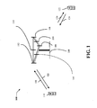
- FIG. 1 illustrates a wireless communication system in accordance with various aspects set forth herein.
- FIG. 2 illustrates a wireless communication system in accordance with further aspects of the present invention.
- FIG. 3A illustrates an exemplary non-limiting high-level block diagram of a system that facilitates pilot channel multiplexing according to various aspects of the present invention.
- FIG. 3B illustrates a base station receiving signals from a plurality of user equipment such that uplink pilot signals can be adaptively multiplexed according to various aspects of the present invention.
- FIG. 4 depicts an exemplary non-limiting adaptive pilot multiplexing scheme according to various aspects of the present invention.
- FIG. 5 illustrates a communications apparatus for employment within a wireless communications environment according to various aspects of the invention.
- FIG. 6 illustrates one particular high-level methodology for adaptive uplink pilot multiplexing in accordance with various embodiments described herein.
- FIG. 7 illustrates a further particular high-level methodology for adaptive uplink pilot multiplexing in accordance with various embodiments described herein.
- FIG. 8 illustrates an example communication system implemented in accordance with various aspects including multiple cells.
- FIG. 9 illustrates a system that can be utilized in connection with uplink pilot multiplexing with respect to user equipment in accordance with various embodiments.
- FIG. 10 illustrates an exemplary non-limiting block diagram of a base station in accordance with various aspects of the invention.
- FIG. 11 illustrates a system that can be utilized in connection with uplink pilot channel allocation in accordance with various embodiments.
- FIG. 12 illustrates an exemplary wireless terminal (e.g., wireless terminal, mobile device, end node, ...) implemented in accordance with various embodiments.
- wireless terminal e.g., wireless terminal, mobile device, end node, .
- FIG. 13 illustrates an exemplary non-limiting block diagram of a communication system incorporating uplink pilot multiplexing in accordance with various aspects of the invention.
- FIG. 14 illustrates an exemplary non-limiting apparatus that enables multiplexing uplink pilots according to various embodiments of the invention.
- FIG. 15 illustrates an exemplary non-limiting apparatus that facilitates adaptive pilot multiplexing according to various embodiments of the invention.
- a component can be, but is not limited to being, a process running on a processor, a processor, an object, an executable, a thread of execution, a program, and/or a computer.
- an application running on a computing device and the computing device can be a component.
- One or more components can reside within a process and/or thread of execution and a component can be localized on one computer and/or distributed between two or more computers.
- these components can execute from various computer readable media having various data structures stored thereon.
- the components may communicate by way of local and/or remote processes such as in accordance with a signal having one or more data packets (e.g ., data from one component interacting with another component in a local system, distributed system, and/or across a network such as the Internet with other systems by way of the signal).
- components of systems described herein may be rearranged and/or complemented by additional components in order to facilitate achieving the various aspects, goals, advantages, etc., described with regard thereto, and are not limited to the precise configurations set forth in a given figure, as will be appreciated by one skilled in the art.
- a wireless terminal or user equipment can also be called a system, subscriber unit, subscriber station, mobile station, mobile, mobile device, remote station, remote terminal, access terminal, user terminal, terminal, wireless communication device, user agent, or user device.
- a wireless terminal or UE can be a cellular telephone, a cordless telephone, a Session Initiation Protocol (SIP) phone, a wireless local loop (WLL) station, a personal digital assistant (PDA), a handheld device having wireless connection capability, computing device, or other processing device connected to a wireless modem.
- SIP Session Initiation Protocol
- WLL wireless local loop
- PDA personal digital assistant
- a base station can be utilized for communicating with wireless terminal(s) and can also be referred to as an access point, Node B, or some other terminology.
- various aspects or features described herein can be implemented as a method, apparatus, or article of manufacture using standard programming and/or engineering techniques.
- article of manufacture as used herein is intended to encompass a computer program accessible from any computer-readable device, carrier, or media.
- computer-readable media can include but are not limited to magnetic storage devices (e.g ., hard disk, floppy disk, magnetic strips, etc.), optical disks (e.g ., compact disk.(CD), digital versatile disk (DVD), etc.), smart cards, and flash memory devices (e.g ., EPROM, card, stick, key drive, etc.).
- various storage media described herein can represent one or more devices and/or other machine-readable media for storing information.
- a carrier wave can be employed to carry computer-readable electronic data or instructions such as those used in transmitting and receiving voice mail, in accessing a network such as a cellular network, or in instructing a device to perform a specified function.
- machine-readable medium can include, without being limited to, wireless channels and various other media capable of storing, containing, and/or carrying instruction(s) and/or data.
- the word "exemplary” is used herein to mean serving as an example, instance, or illustration. Any aspect or design described herein as “exemplary” is not necessarily to be construed as preferred or advantageous over other aspects or designs. Rather, use of the word exemplary is intended to present concepts in a concrete fashion.
- the term “or” is intended to mean an inclusive “or” rather than an exclusive “or”. That is, unless specified otherwise, or clear from context, "X employs A or B” is intended to mean any of the natural inclusive permutations. That is, if X employs A; X employs B; or X employs both A and B, then "X employs A or B" is satisfied under any of the foregoing instances.
- the articles “a” and “an” as used in this application and the appended claims should generally be construed to mean “one or more” unless specified otherwise or clear from context to be directed to a singular form.
- the terms to "infer” or “inference” refer generally to the process of reasoning about or inferring states of the system, environment, and/or user from a set of observations as captured via events and/or data. Inference can be employed to identify a specific context or action, or can generate a probability distribution over states, for example. The inference can be probabilistic-that is, the computation of a probability distribution over states of interest based on a consideration of data and events. Inference can also refer to techniques employed for composing higher-level events from a set of events and/or data. Such inference results in the construction of new events or actions from a set of observed events and/or stored event data, whether or not the events are correlated in close temporal proximity, and whether the events and data come from one or several event and data sources.
- CDMA Code Division Multiple Access
- TDMA Time Division Multiple Access
- FDMA Frequency Division Multiple Access
- OFDMA Orthogonal FDMA
- SC-FDMA Single-Carrier FDMA
- a CDMA network may implement a radio technology such as Universal Terrestrial Radio Access (UTRA), cdma2000, etc.
- UTRA includes Wideband-CDMA (W-CDMA) and Low Chip Rate (LCR).
- cdma2000 covers IS-2000, IS-95 and IS-856 standards.
- a TDMA network may implement a radio technology such as Global System for Mobile Communications (GSM).
- GSM Global System for Mobile Communications
- An OFDMA network may implement a radio technology such as Evolved UTRA (E-UTRA), IEEE 802.11, IEEE 802.16, IEEE 802.20, Flash-OFDM®, etc.
- E-UTRA, E-UTRA, and GSM are part of Universal Mobile Telecommunication System (UMTS).
- LTE Long Term Evolution
- UTRA, E-UTRA, GSM, UMTS and LTE are described in documents from an organization named "3rd Generation Partnership Project" (3GPP).
- cdma2000 is described in documents from an organization named "3rd Generation Partnership Project 2" (3GPP2).
- SC-FDMA which utilizes single carrier modulation and frequency domain equalization is a technique attractive for uplink multiple access for its inherent transmit power efficiency.
- SC-FDMA has similar performance and essentially the same overall complexity as those of OFDMA system.
- SC-FDMA signal has lower peak-to-average power ratio (PAPR) because of its inherent single carrier structure.
- PAPR peak-to-average power ratio
- SC-FDMA has drawn great attention, especially in the uplink communications where lower PAPR greatly benefits the mobile terminal in terms of transmit power efficiency.
- SC-FDMA is currently a working assumption for uplink multiple access scheme in 3GPP Long Term Evolution (LTE), or Evolved UTRA.
- LTE Long Term Evolution
- LTE utilizes orthogonal frequency division multiplexing (OFDM) on the downlink and single-carrier frequency division multiplexing (SC-FDM) on the uplink.
- OFDM and SC-FDM partition the system bandwidth into multiple (N) orthogonal subcarriers, which are also commonly referred to as tones, bins, etc.
- N orthogonal subcarriers
- Each subcarrier may be modulated with data.
- modulation symbols are sent in the frequency domain with OFDM and in the time domain with SC-FDM.
- the spacing between adjacent subcarriers may be fixed, and the total number of subcarriers (N) may be dependent on the system bandwidth.
- N 512 for a system bandwidth of 5 MHz
- N 1024 for a system bandwidth of 10 MHz
- N 2048 for a system bandwidth of 20 MHz.
- N may be any integer value.
- Access point 100 includes multiple antenna groups, one including 104 and 106, another including 108 and 110, and an additional including 112 and 114. In Fig. 1 , only two antennas are shown for each antenna group, however, more or fewer antennas may be utilized for each antenna group.
- Access terminal 116 is in communication with antennas 112 and 114, where antennas 112 and 114 transmit information to access terminal 116 over forward link 120 and receive information from access terminal 116 over reverse link 118.
- Access terminal 122 is in communication with antennas 106 and 108, where antennas 106 and 108 transmit information to access terminal 122 over forward link 126 and receive information from access terminal 122 over reverse link 124.
- communication links 118, 120, 124 and 126 may use different frequency for communication.
- forward link 120 may use a different frequency than that used by reverse link 118.
- antenna groups each are designed to communicate to access terminals in a sector of the areas covered by access point 100.
- the transmitting antennas of access point 100 utilize beamforming in order to improve the signal-to-noise ratio of forward links for the different access terminals 116 and 124. Also, an access point using beamforming to transmit to access terminals scattered randomly through its coverage causes less interference to access terminals in neighboring cells than an access point transmitting through a single antenna to all its access terminals.
- an access point may be a fixed station used for communicating with the terminals and may also be referred to as an access point, a Node B, or some other terminology.
- An access terminal may also be called an access terminal, user equipment (UE), a wireless communication device, terminal, access terminal or some other terminology.
- UE user equipment
- FIG. 2 illustrates a wireless communication system 200 with multiple base stations 210 and multiple terminals 220 as may be utilized in conjunction with one or more aspects of the present invention.
- a base station is generally a fixed station that communicates with the terminals and may also be called an access point, a Node B, or some other terminology.
- Each base station 210 provides communication coverage for a particular geographic area, illustrated as three geographic areas, labeled 202a, 202b, and 202c.
- the term "cell" can refer to a base station and/or its coverage area depending on the context in which the term is used. To improve system capacity, a base station coverage area may be partitioned into multiple smaller areas ( e.g ., three smaller areas, according to cell 202a in FIG.
- Each smaller area can be served by a respective base transceiver subsystem (BTS).
- BTS base transceiver subsystem
- the term "sector” can refer to a BTS and/or its coverage area depending on the context in which the term is used. For a sectorized cell, the BTSs for all sectors of that cell are typically co-located within the base station for the cell.
- the transmission techniques described herein may be used for a system with sectorized cells as well as a system with un-sectorized cells.
- base station is used generically for a fixed station that serves a sector as well as a fixed station that serves a cell.
- Terminals 220 are typically dispersed throughout the system, and each terminal may be fixed or mobile.
- a terminal may also be called a mobile station, user equipment, a user device, or some other terminology.
- a terminal may be a wireless device, a cellular phone, a personal digital assistant (PDA), a wireless modem card, and so on.
- PDA personal digital assistant
- Each terminal 220 may communicate with zero, one, or multiple base stations on the downlink and uplink at any given moment.
- the downlink (or forward link) refers to the communication link from the base stations to the terminals
- the uplink or reverse link refers to the communication link from the terminals to the base stations.
- a system controller 230 couples to base stations 210 and provides coordination and control for base stations 210.
- base stations 210 may communicate with one another as needed.
- Data transmission on the forward link occurs from one access point to one access terminal at or near the maximum data rate that can be supported by the forward link and/or the communication system.
- Additional channels of the forward link e.g ., control channel
- Reverse link data communication may occur from one access terminal to one or more access points via one or more antennas at the terminals 220 and or at the base stations 210, as described above with respect to FIG. 1 .
- FIG. 3A illustrates an exemplary non-limiting high-level block diagram of a system that facilitates pilot channel multiplexing according to various aspects of the present invention.
- the system 300A includes user equipment 302 that is communicatively coupled to a base station 304 in a wireless manner.
- base station 304 is providing voice and/or data services to UE 302 over a downlink 310 and receiving communications from user equipment 302 over an uplink 312, such as a SC-FDMA uplink.
- User equipment 302 can be mobile in nature, such that quality associated with signals received from base station 304 can vary as UE 302 translates to a different geographic region.
- User equipment 302 can include a pilot multiplexer 306 that can adaptively multiplex uplink pilot signals in accordance with the schemes discussed herein to enable channel condition estimation among other functions.
- base station 304 can demultiplex pilot signals using pilot demultiplexer 308 such that the adaptively multiplexed pilot signals can be used to improve channel estimation and suppress interference from other UE.
- UE 302 and/or base station 304 can include other ancillary components which facilitates, among other functions, communication of associated information or data used to adaptively determine the pilot allocation scheme.
- the base station can transmit the number of active wireless terminals 302 for SDMA or streams for SU-MIMO and the pilot allocation identifier such that the subject UE 302, the base station 304, and the other active wireless terminals can adaptively determine the pilot multiplexing scheme.
- uplink 312 and downlink channels 310 are shown as a single arrow, it is to be appreciated that the invention contemplates the use of a plurality of transmit and receive antennas, such as would be the case for a single-user MIMO (SU-MIMO) system.
- SU-MIMO single-user MIMO
- the term "multiplex" in the context of user equipment 302 uplink channel as described herein refers to the process of selecting bandwidth resources in such a manner as to preserve orthogonality of pilots while facilitating simultaneous transmission from multiple transmission sources (e.g ., antennas) over a shared medium (e.g ., a wireless channel), depending on the context, in addition to conventional definitions of the word referring to physical combination of signals.
- multiple transmit antennas in a UE 302 or portion thereof can be used to transmit on the uplink channel simultaneously (multiplexed) according to the scheme as described herein, while the multiplexed signals may not be physically combined in the UE 302 or portion thereof.
- multiple individual UE 302 may simultaneously transmit on a channel over a single antenna, where no actual signal combination occurs in the UE 302 or portion thereof. Rather, the process of multiplexing in this instance refers to the selection of specific portions of shared resources by UE 302 such that the individual signals can be simultaneously transmitted over a shared physical channel and subsequently demultiplexed.
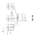
- FIG. 3B illustrates a base station 304 receiving signals from a plurality ofUE 302 such that uplink pilot signals are adaptively multiplexed according to various aspects of the present invention.
- Base station 304 is shown receiving signals from a plurality ofUE 302 (1-Z), Z being an integer, such as would be the case for an multiuser MIMO (MU-MIMO) space-division multiple access (SDMA) system.
- MU-MIMO multiuser MIMO
- SDMA space-division multiple access
- Logical Control Channels comprise Broadcast Control Channel (BCCH), which is a DL channel for broadcasting system control information.
- PCCH Paging Control Channel
- MCCH Multicast Control Channel
- MBMS Multimedia Broadcast and Multicast Service
- Dedicated Control Channel is point-to-point bi-directional channel that transmits dedicated control information and used by UEs 302having an RRC connection.
- logical traffic channels comprise a Dedicated Traffic Channel (DTCH), which is point-to-point bi-directional channel, dedicated to one UE for the transfer of user information.
- DTCH Dedicated Traffic Channel
- MTCH Point-to-multipoint DL channel for transmitting traffic data.
- transport channels are classified into DL and UL.
- DL transport channels comprise a Broadcast Channel (BCH), Downlink Shared Data Channel (DL-SDCH), and a Paging Channel (PCH), the PCH for support of UE power saving (Discontinuous Reception (DRX) cycle is indicated by the network to the UE), broadcasted over entire cell and mapped to PHY resources, which can be used for other control/traffic channels.
- the UL transport channels comprise a Random Access Channel (RACH), a Request Channel (REQCH), a Uplink Shared Data Channel (UL-SDCH) and plurality of PHY channels.
- the PHY channels comprise a set of DL channels and UL channels.
- the DL PHY channels comprise:
- the UL PHY Channels comprises:
- a channel structure that preserves low PAR (e.g ., at any given time, the channel is contiguous or uniformly spaced in frequency) properties of a single carrier waveform.
- the invention advantageously maintains pilot orthogonality for improved channel estimation and suppression of channel interference.
- the invention advantageously maintains a single carrier ' waveform on the pilot channel for improved wireless transmit power efficiency for wireless terminals on the uplink channel.
- SDCH is a Shared Data Channel
- PICH is a Pilot Channel
- RB is a Resource Block
- LB and SB refers to Long Block and Short Block respectively
- a Slot is 0.5 millisecond (ms) collection of RBs comprising 6 LBs and 2 SBs
- TTI is a Transmission Time Interval comprising 2 slots.
- FIG. 4 depicts an exemplary non-limiting adaptive pilot allocation scheme 400 according to various aspects of the present invention for up to four streams (e.g ., stream 0, 1, 2, and 3).
- a stream could refer to one of a multiple of uplink transmissions from a single wireless UE 302 (e.g ., SU-MIMO), to one of a multiple of uplink transmissions from a multiple wireless UE 302 ( e.g ., SDMA), or to any combination thereof, and the like.
- SDCH and PICH are shown as occupying respective LB 408 and SB 410, such a choice is not essential to the function of the invention.
- such a multiplexing structure can comprise a 1 ms TTI 404 split into 12 LB 408 and 4 SB 410, where SDCH can be transmitted on 12 LB 408, and PICH can be transmitted on 4 SB 410.
- the FDM PICH structure for 1 RB spans 180 KHz and is the minimum unit of transmission in the uplink.
- the PICH granularity is 30 KHz, in other words, the PICH bandwidth can increase in increments of 30 KHz or provide 6 tones for each minimum unit of transmission in the uplink.
- FIG. 4 depicts the results of an adaptive pilot multiplexing scheme where the PICH structure is adaptive such that the PICH bandwidth per symbol is a function of number of streams being multiplexed according to various non-limiting embodiments of the invention.
- FIG. 4 can represent 4 streams from a single user or 1 stream each from 4 users as described above.
- the grey-cell area denotes the LB 408 where SDCH from all streams is sent.
- the PICH is sent in SB 402 and the PICH frequency division FDM orthogonality can be shown by the indicators "0" for stream 1, "1 " for stream 2, "2" for stream 3, and "3" for stream 4.
- the PICH bandwidth and frequency location per SB 402 can vary in time as a function of the number of active streams (e.g ., current transmission on the uplink channel, whether from SU-MIMO, SDMA, or any combination thereof).
- the PICH for each stream has the same constant time/bandwidth allocation spanning the entire 1 ms TTI 404.
- the invention advantageously provides a PICH waveform that preserves the low PAR single carrier waveform for improved wireless transmit power efficiency by cyclically shifting PICH frequency location for each stream across SB in time while maintain PICH per stream contiguous in frequency, according to various aspects of the invention.
- the provided adaptive pilot multiplexing schemes maintain orthogonality per SB 402 as the PICH per stream can be frequency division multiplexed in an orthogonal manner to improve channel estimation and suppress other wireless terminals' interference.
- the first 0.5 ms slot shows the stream 1 first at the upper end of the RB 406 occupying the upper three tones.
- the stream hops to the lower portion of RB 406 occupying the lower three tones.
- the pattern then repeats, resulting in a PICH per stream contiguous in frequency with constant time/bandwidth allocation spanning the entire 1 ms TTI 404.
- the multiplexing scheme adapts while maintaining the aforementioned advantages (e.g ., single carrier, orthogonality, constant time/bandwidth allocation spanning a TTI).
- the pattern is non-repeating within the TTI 404, but maintains the PICH per stream contiguous in frequency with constant time/bandwidth allocation spanning the entire 1 ms TTI 404.
- the PICH structure in FIG. 4 can be extended for N RB and M streams as follows.
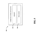
- the apparatus 500 can be a base station 304 or a portion thereof or user equipment 302 or a portion thereof (such as a secure digital (SD) card coupled to a processor).
- Apparatus 500 can include a memory 502 that retains various instructions with respect to signal processing, scheduling communications, requesting measurement gaps, and/or the like. For instance, if apparatus 500 is user equipment as described below in connection with FIGS. 11-12 and 15 , memory 502 can include instructions for analyzing quality of signals on an uplink and/or downlink channel with respect to a particular base station.
- memory 502 can comprise instructions for adaptively multiplexing PICH by varying the PICH bandwidth and frequency location per SB 402 in time as a function of the number of active streams.
- memory 502 can comprise instructions for receiving and processing uplink pilot channel data (e.g ., number of active streams and/or indicated starting frequency location, number of available RBs 406, any combination thereof, and/or the like) from a base station 304 in order to facilitate adaptively multiplexing uplink pilots according to a predetermined scheme, in accordance with various aspects of the invention.
- memory 502 can comprise instructions for facilitating transmission of the adaptively multiplexed PICH.
- the above example instructions and other suitable instructions can be retained within memory 502, and a processor 504 can be utilized in connection with executing the instructions (depending upon, for instance, number of active streams, frequency starting position, etc .).
- apparatus 500 can be a base station and/or a portion thereof as described below in connection with FIGS. 9-10 and 14 .
- memory 502 can include instructions for receiving an indication that user equipment serviced by apparatus 500 is taking measurements with respect to other technologies and/or frequencies.
- Memory 502 can additionally include instructions for determining and transmitting uplink pilot channel data (e.g ., number of active streams and/or indicated starting frequency location, number of available RBs 406, any combination thereof, and/or the like) to UE 302 in order to facilitate demultiplexing the adaptively multiplexed PICH according to a predetermined scheme, in accordance with various aspects of the invention.
- uplink pilot channel data e.g ., number of active streams and/or indicated starting frequency location, number of available RBs 406, any combination thereof, and/or the like
- memory 502 can further include instructions for facilitating reception of the adaptively multiplexed PICH.
- Processor 504 can be employed to execute instructions retained within memory 502. While several examples have been provided, it is understood that instructions described in the form of methodologies ( e.g ., FIGS. 6-7 ) can be included within memory 502 and executed by processor 504.
- FIGS. 6 and 7 particular high-level methodologies for adaptive uplink pilot multiplexing in accordance with various embodiments are illustrated. While, for purposes of simplicity of explanation, the methodologies are shown and described as a series of acts, it is to be understood and appreciated that the methodologies are not limited by the order of acts, as some acts can occur in different orders and/or concurrently with other acts from that shown and described herein. For example, those skilled in the art will understand and appreciate that a methodology could alternatively be represented as a series of interrelated states or events, such as in a state diagram. Moreover, not all illustrated acts may be utilized to implement a methodology in accordance with one or more embodiments.
- FIG. 6 illustrates one particular high-level methodology 600 facilitating uplink pilot multiplexing in connection with adaptive pilot multiplexing schemes described herein.
- uplink pilot channel information e.g ., number of active streams and/or indicated starting frequency location, number of available RBs 406, any combination thereof, and/or the like
- the respective uplink pilot channel information is transmitted to one or more UE 302 to facilitate UE 302 adaptive pilot multiplexing by varying the pilot channel bandwidth and frequency location per SB 402 in time according to the predetermined function of the number of active streams.
- base station 304, or a portion thereof demultiplexes the multiplexed pilot channel according to the predetermined function and the respective uplink pilot channel information.
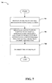
- FIG. 7 illustrates one particular high-level methodology 700 for facilitating uplink pilot multiplexing in connection with adaptive pilot multiplexing schemes described herein.
- UE 302 or a portion thereof adaptively multiplexes pilots at 706 by varying the pilot channel bandwidth and frequency location per SB 402 in time according to a predetermined function of the number of active streams.
- the UE 302 or a portion thereof transmits the adaptively multiplexed pilots.
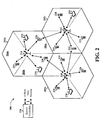
- FIG. 8 depicts an example communication system 800 implemented in accordance with various aspects including multiple cells: cell I 802, cell M 804. Note that neighboring cells 802 and 804 overlap slightly, as indicated by cell boundary region 868, thereby creating potential for signal interference between signals transmitted by base stations in neighboring cells.
- Cell 802 includes a first sector, sector I810, a second sector, sector II 812, and a third sector, sector III 814. Each sector 810, 812, 814 has two sector boundary regions; each boundary region is shared between two adjacent sectors.
- Sector boundary regions provide potential for signal interference between signals transmitted by base stations in neighboring sectors.
- Line 816 represents a sector boundary region between sector I 810 and sector II 812;
- line 818 represents a sector boundary region between sector II 812 and sector III 814;
- line 820 represents a sector boundary region between sector III 814 and sector 1 810.
- cell M 804 includes a first sector, sector I 822, a second sector, sector II 824, and a third sector, sector III 826.
- Line 828 represents a sector boundary region between sector I 822 and sector II 824;
- line 830 represents a sector boundary region between sector II 824 and sector III 826;
- line 832 represents a boundary region between sector III 826 and sector I 822.
- Cell I 802 includes a base station (BS), base station I 806, and a plurality of end nodes (ENs) (e.g ., wireless terminals) in each sector 810, 812, 814.
- Sector I 810 includes EN(1) 836 and EN(X) 838 coupled to BS 806 via wireless links 840, 842, respectively;
- sector II 812 includes EN(1') 844 and EN(X') 846 coupled to BS 806 via wireless links 848, 850, respectively;
- sector III 814 includes EN(1") 852 and EN(X") 854 coupled to BS 806 via wireless links 856, 858, respectively.
- cell M 804 includes base station M 808, and a plurality of end nodes (ENs) in each sector 822, 824, 826.
- Sector I 822 includes EN(1) 836' and EN(X) 838' coupled to BS M 808 via wireless links 840', 842'; respectively;
- sector II 824 includes EN(1') 844' and EN(X') 846' coupled to BS M 808 via wireless links 848', 850', respectively;
- sector 3 826 includes EN(1") 852' and EN(X") 854' coupled to BS 808 via wireless links 856', 858', respectively.
- System 800 also includes a network node 860 which is coupled to BS I 806 and BS M 808 via network links 862, 864, respectively.
- Network node 860 is also coupled to other network nodes, e.g ., other base stations, AAA server nodes, intermediate nodes, routers, etc. and the Internet via network link 866.
- Network links 862, 864, 866 can be, e.g ., fiber optic cables.
- Each end node, e.g., EN(1) 836 can be a wireless terminal including a transmitter as well as a receiver. The wireless terminals, e.g., EN(1) 836 can move through system 800 and can communicate via wireless links with the base station in the cell in which the EN is currently located.
- the wireless terminals, (WTs), e.g ., EN(1) 836 can communicate with peer nodes, e.g ., other WTs in system 800 or outside system 800 via a base station, e.g ., BS 806, and/or network node 860.
- WTs, e.g ., EN(1) 836 can be mobile communications devices such as cell phones, personal data assistants with wireless modems, etc .
- Respective base stations or portions thereof can perform pilot uplink channel information determination and transmission. Additionally, respective base stations or portions thereof can perform uplink pilot demultiplexing according to the various aspects provided herein.
- the wireless terminals or portions thereof can use the provided respective uplink pilot channel information to facilitate adaptively multiplexing pilots by varying the pilot channel bandwidth and frequency location per SB 402 in time according to a predetermined function of the number of active streams according to the various aspects provided herein. Additionally, wireless terminals or portions thereof can transmit multiplexed pilots to the respective base stations
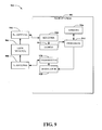
- FIG. 9 illustrates a system that can be utilized in connection with adaptive uplink pilot multiplexing schemes with respect to user equipment.
- System 900 comprises a base station 902 with a receiver 910 that receives signal(s) from one or more user devices 904 by way of one or more receive antennas 906, and transmits to the one or more user devices 904 through a plurality of transmit antennas 908.
- receive antennas 906 and transmit antennas 908 can be implemented using a single set of antennas.
- Receiver 910 can receive information from receive antennas 906 and is operatively associated with a demodulator 912 that demodulates received information.
- Receiver 910 can be, for example, a Rake receiver (e.g., a technique that individually processes multi-path signal components using a plurality of baseband correlators, ...), an MMSE-based receiver, or some other suitable receiver for separating out user devices assigned thereto, as will be appreciated by one skilled in the art. For instance, multiple receivers can be employed (e.g., one per receive antenna), and such receivers can communicate with each other to provide improved estimates of user data. Demodulated symbols are analyzed by a processor 914 similar to processor 1106 described below with regard to FIG. 11 , and is coupled to a memory 916 that stores information related to user device assignments, lookup tables related thereto and the like. Receiver output for each antenna can be jointly processed by receiver 910 and/or processor 914. A modulator 918 can multiplex the signal for transmission by a transmitter 920 through transmit antennas 908 to user devices 904.
- a Rake receiver e.g., a technique that individually processes multi-path signal components using a plurality
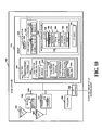
- FIG. 10 illustrates an example base station 1000 in accordance with various aspects of the present invention.
- Base station 1000 or portions thereof implements various aspect of the present invention.
- base station 1000 can determine pilot uplink channel information determination for subsequent transmission to facilitate adaptive pilot multiplexing in associated user equipment.
- Base station 1000 can be used as any one of base stations 806, 808 of the system 800 of FIG. 8 .
- the base station 1000 includes a receiver 1002, a transmitter 1004, a processor 1006, e.g ., CPU, an input/output interface 1008 and memory 1010 coupled together by a bus 1009 over which various elements 1002, 1004, 1006, 1008, and 1010 can interchange data and information.
- Sectorized antenna 1003 coupled to receiver 1002 is used for receiving data and other signals, e.g ., channel reports, from wireless terminals transmissions from each sector within the base station's cell and can comprise one or more receive antennas.
- Sectorized antenna 1005 coupled to transmitter 1004 is used for transmitting data and other signals, e.g ., control signals, pilot signal, beacon signals, etc. to wireless terminals 1200 (see FIG. 12 ) within each sector of the base station's cell.
- base station 1000 can employ multiple receivers 1002 and multiple transmitters 1004, e.g ., an individual receiver 1002 for each sector and an individual transmitter 1004 for each sector. As described above, it is to be appreciated that various modifications are possible.
- Processor 1006 can be, e.g ., a general purpose central processing unit (CPU).
- Processor 1006 controls operation of base station 1000 under direction of one or more routines 1018 stored in memory 1010 and implements the methods.
- I/O interface 1008 provides a connection to other network nodes, coupling the BS 1000 to other base stations, access routers, AAA server nodes, etc., other networks, and the Internet.
- Memory 1010 includes routines 1018 and data/information 1020.
- Data/information 1020 includes data 1036, tone subset allocation sequence information 1038 including downlink strip-symbol time information 1040 and downlink tone information 1042, and wireless terminal (WT) data/info 1044 including a plurality of sets of WT information: WT 1 info 1046 and WT N info 1060.
- Each set of WT info, e.g ., WT 1 info 1046 includes data 1048, terminal ID 1050, sector ID 1052, uplink channel information 1054, downlink channel information 1056, and mode information 1058.
- Routines 1018 include communications routines 1022 and base station control routines 1024.
- Base station control routines 1024 includes a scheduler module 1026 and signaling routines 1028 including a tone subset allocation routine 1030 for strip-symbol periods, other downlink tone allocation hopping routine 1032 for the rest of symbol periods, e.g ., non strip-symbol periods, and a beacon routine 1034.
- Data 1036 includes data to be transmitted that will be sent to encoder 1014 of transmitter 1004 for encoding prior to transmission to WTs, and received data from WTs that has been processed through decoder 1012 of receiver 1002 following reception.
- Downlink strip-symbol time information 1040 includes the frame synchronization structure information, such as the superslot, beaconslot, and ultraslot structure information and information specifying whether a given symbol period is a strip-symbol period, and if so, the index of the strip-symbol period and whether the strip-symbol is a resetting point to truncate the tone subset allocation sequence used by the base station.
- Downlink tone information 1042 includes information including a carrier frequency assigned to the base station 1000, the number and frequency of tones, and the set of tone subsets to be allocated to the strip-symbol periods, and other cell and sector specific values such as slope, slope index and sector type.
- Data 1048 can include data that WT1 1200 has received from a peer node, data that WT 1 1200 desires to be transmitted to a peer node, and downlink channel quality report feedback information.
- Terminal ID 1050 is a base station 1000 assigned ID that identifies WT 1 1200.
- Sector ID 1052 includes information identifying the sector in which WT1 1200 is operating. Sector ID 1052 can be used, for example, to determine the sector type.
- Uplink channel information 1054 includes information identifying channel segments that have been allocated by scheduler 1026 for WT1 1200 to use, e.g ., uplink traffic channel segments for data, dedicated uplink control channels for requests, power control, timing control, number of active streams etc .
- Each uplink channel assigned to WT1 1200 includes one or more logical tones, each logical tone following an uplink hopping sequence according to various aspects of the present invention.
- Downlink channel information 1056 includes information identifying channel segments that have been allocated by scheduler 1026 to carry data and/or information to WT1 1200, e.g ., downlink traffic channel segments for user data.
- Each downlink channel assigned to WT1 1200 includes one or more logical tones, each following a downlink hopping sequence.
- Mode information 1058 includes information identifying the state of operation of WT1 1200, e.g . sleep, hold, on.
- Communications routines 1022 control the base station 1000 to perform various communications operations and implement various communications protocols.
- Base station control routines 1024 are used to control the base station 1000 to perform basic base station functional tasks, e.g ., signal generation and reception, scheduling, and to implement the steps of the method of some aspects including transmitting signals to wireless terminals using the tone subset allocation sequences during the strip-symbol periods.
- Signaling routine 1028 controls the operation of receiver 1002 with its decoder 1012 and transmitter 1004 with its encoder 1014.
- the signaling routine 1028 is responsible for controlling the generation of transmitted data 1036 and control information.
- Tone subset allocation routine 1030 constructs the tone subset to be used in a strip-symbol period using the method of the aspect and using data/information 1020 including downlink strip-symbol time info 1040 and sector ID 1052.
- the downlink tone subset allocation sequences will be different for each sector type in a cell and different for adjacent cells.
- the WTs 1200 receive the signals in the strip-symbol periods in accordance with the downlink tone subset allocation sequences; the base station 1000 uses the same downlink tone subset allocation sequences in order to generate the transmitted signals.
- Other downlink tone allocation hopping routine 1032 constructs downlink tone hopping sequences, using information including downlink tone information 1042, and downlink channel information 1056, for the symbol periods other than the strip-symbol periods.
- the downlink data tone hopping sequences are synchronized across the sectors of a cell.
- Beacon routine 1034 controls the transmission of a beacon signal, e.g ., a signal of relatively high power signal concentrated on one or a few tones, which can be used for synchronization purposes, e.g ., to synchronize the frame timing structure of the downlink signal and therefore the tone subset allocation sequence with respect to an ultra-slot boundary.
- FIG. 11 illustrates a system 1100 that can be utilized in connection with adaptive uplink pilot multiplexing schemes as described herein.
- System 1100 comprises a receiver 1102 that receives a signal from, for instance, one or more receive antennas, and performs typical actions thereon (e.g., filters, amplifies, downconverts, ...) the received signal and digitizes the conditioned signal to obtain samples.
- a demodulator 1104 can demodulate and provide received pilot symbols to a processor 1106 for channel estimation.
- Processor 1106 can be a processor dedicated to analyzing information received by receiver component 1102 and/or generating information for transmission by a transmitter 1114.
- Processor 1106 can be a processor that controls one or more portions of system 1100, and/or a processor that analyzes information received by receiver 1102, generates information for transmission by a transmitter 1114, and controls one or more portions of system 1100.
- System 1100 can include an optimization component 1108 that can optimize performance of user equipment before, during, and/or after performance of measurements with respect to one or more technologies and/or frequencies. Optimization component 1108 can be incorporated into the processor 1106. It is to be appreciated that optimization component 1108 can include optimization code that performs utility based analysis in connection with requesting measurement gaps. The optimization code can utilize artificial intelligence based methods in connection with performing inference and/or probabilistic determinations and/or statistical-based determination in connection with encoding and decoding schemes.
- System (user equipment) 1100 can additionally comprise memory 1110 that is operatively coupled to processor 1106 and that stores information such as measurement gap information, scheduling information, and the like, wherein such information can be employed in connection with allocating requesting measurement gaps and performing measurements during a measurement gap.
- Memory 1110 can additionally store protocols associated with generating lookup tables, etc., such that system 1100 can employ stored protocols and/or algorithms to increase system capacity.
- the data store (e.g., memories) components described herein can be either volatile memory or nonvolatile memory, or can include both volatile and nonvolatile memory.
- nonvolatile memory can include read only memory (ROM), programmable ROM (PROM), electrically programmable ROM (EPROM), electrically erasable ROM (EEPROM), or flash memory.
- Volatile memory can include random access memory (RAM), which acts as external cache memory.
- RAM is available in many forms such as synchronous RAM (SRAM), dynamic RAM (DRAM), synchronous DRAM (SDRAM), double data rate SDRAM (DDR SDRAM), enhanced SDRAM (ESDRAM), Synchlink DRAM (SLDRAM), and direct Rambus RAM (DRRAM).
- SRAM synchronous RAM
- DRAM dynamic RAM
- SDRAM synchronous DRAM
- DDR SDRAM double data rate SDRAM
- ESDRAM enhanced SDRAM
- SLDRAM Synchlink DRAM
- DRRAM direct Rambus RAM
- the memory 1110 is intended to comprise, without being limited to, these and any other suitable types of memory.
- Processor 1106 is connected to a symbol modulator 1112 and transmitter 1114 that transmits the modulated signal.
- FIG. 12 illustrates an exemplary wireless terminal (e.g ., end node, mobile device, ...) 1200 which can be used as any one of the wireless terminals ( e.g ., EN(1) 836, of the system 800 shown in FIG. 8 ) .
- Wireless terminal 1200 includes a receiver 1202 including a decoder 1212, a transmitter 1204 including an encoder 1214, a processor 1206, and memory 1208 which are coupled together by a bus 1210 over which the various elements 1202, 1204, 1206, 1208 can interchange data and information.
- Antenna 1203 used for receiving signals from a base station is coupled to receiver 1202.
- Antenna 1205 used for transmitting signals, e.g ., to a base station is coupled to transmitter 1204.
- multiple transmit and receive antennas, receivers, etc. in the base station and user equipment can be used.
- multiple users can transmit and receive signals from a base station having multiple transmit and receive antennas, receivers, etc.
- the processor 1206, e.g ., a CPU controls the operation of the wireless terminal 1200 and implements methods by executing routines 1220 and using data/information 1222 in memory 1208.
- Data/information 1222 includes user data 1234, user information 1236, and tone subset allocation sequence information 1250, in the example case of an OFDMA communication system.
- User data 1234 can include data, intended for a peer node, which can be routed to encoder 1214 for encoding prior to transmission by transmitter 1204 to base station 1000, and data received from the base station 1000 which has been processed by the decoder 1212 in receiver 1202.
- User information 1236 includes uplink channel information 1238, downlink channel information 1240, terminal ID information 1242, base station ID information 1244, sector ID information 1246, and mode information 1248.
- Uplink channel information 1238 includes information identifying uplink channels segments that have been assigned by base station 1000 for wireless terminal 1200 to use when transmitting to the base station 1000.
- Uplink channels can include uplink traffic channels, dedicated uplink control channels, e.g., request channels, power control channels and timing control channels.
- each uplink channel includes one or more logic tones, each logical tone following an uplink tone hopping sequence.
- the uplink hopping sequences are different between each sector type of a cell and between adjacent cells.
- Downlink channel information 1240 includes information identifying downlink channel segments that have been assigned by a base station to WT 1200 for use when the base station is transmitting data/information to WT 1200.
- Downlink channels can include downlink traffic channels and assignment channels, each downlink channel including one or more logical tone, each logical tone following a downlink hopping sequence, which is synchronized between each sector of the cell.
- User info 1236 also includes terminal ID information 1242, which is a base station 1000 assigned identification, base station ID information 1244 which identifies the specific base station 1000 that WT has established communications with, and sector ID info 1246 which identifies the specific sector of the cell where WT 1200 is presently located.
- terminal ID information 1242 which is a base station 1000 assigned identification
- base station ID information 1244 which identifies the specific base station 1000 that WT has established communications with
- sector ID info 1246 which identifies the specific sector of the cell where WT 1200 is presently located.
- base station ID 1244 provides a cell slope value
- sector ID info 1246 provides a sector index type; the cell slope value and sector index type can be used to derive tone hopping sequences.
- Mode information 1248 also included in user info 1236 identifies whether the WT 1200 is in sleep mode, hold mode, or on mode.
- tone subset allocation sequence information 1250 includes downlink strip-symbol time information 1252 and downlink tone information 1254.
- Downlink tone info 1254 includes information including a carrier frequency assigned to the base station 1000, the number and frequency of tones, and the set of tone subsets to be allocated to the strip-symbol periods, and other cell and sector specific values such as slope, slope index and sector type.
- Routines 1220 include communications routines 1224 and wireless terminal control routines 1226. Communications routines 1224 control the various communications protocols used by WT 1200. Wireless terminal control routines 1226 controls basic wireless terminal 1200 functionality including the control of the receiver 1202 and transmitter 1204. Wireless terminal control routines 1226 include the signaling routine 1228.
- tone subset allocation routine 1230 uses user data/info 1222 including downlink channel information 1240, base station ID info 1244, e.g., slope index and sector type, and downlink tone information 1254 in order to generate the downlink tone subset allocation sequences in accordance with some embodiments and process received data transmitted from base station 1000.
- Some embodiments can be implemented using software, hardware and/or a combination of software and hardware. Some embodiments are directed to an apparatus, e.g ., a mobile node such as a mobile terminal, a base station, or a communications system which implement some embodiments. Some embodiments are also directed to methods, e.g ., method of controlling and/or operating mobile nodes, base stations and/or communications systems, e.g ., hosts, in accordance with some embodiments. Some embodiments are also directed to machine readable medium, e.g ., ROM, RAM, CDs, hard discs, etc., which include machine readable instructions for controlling a machine to implement one or more steps in accordance with some embodiments.
- nodes described herein are implemented using one or more modules to perform the steps corresponding to one or more methods of some embodiments, for example, signal processing, message generation and/or transmission steps.
- modules can be implemented using software, hardware or a combination of software and hardware.
- Many of the above described methods or method steps can be implemented using machine executable instructions, such as software, included in a machine readable medium such as a memory device, e.g ., RAM, floppy disk, etc. to control a machine, e.g ., general purpose computer with or without additional hardware, to implement all or portions of the above described methods, e.g ., in one or more nodes.
- some embodiments are directed to a machine-readable medium including machine executable instructions for causing a machine, e.g ., processor and associated hardware, to perform one or more of the steps of the above-described method(s).
- the methods and apparatus of some embodiments can be, and in various embodiments are, used with CDMA, orthogonal frequency division multiplexing (OFDM), SC-FDMA, and/or various other types of communications techniques which can be used to provide wireless communications links between access nodes and mobile nodes.
- the access nodes are implemented as base stations which establish communications links with mobile nodes using OFDM and/or CDMA.
- the mobile nodes are implemented as notebook computers, personal data assistants (PDAs), or other portable devices including receiver/transmitter circuits and logic and/or routines, for implementing the methods of some embodiments.
- inferences can be made regarding determining uplink pilot channel information.
- the term to "infer” or “inference” refers generally to the process of reasoning about or inferring states of the system, environment, and/or user, mobile device, active uplink streams, and base station from a set of observations as captured via events and/or data. Inference can be employed to identify a specific context or action, or can generate a probability distribution over states, for example. The inference can be probabilistic-that is, the computation of a probability distribution over states of interest based on a consideration of data and events. Inference can also refer to techniques employed for composing higher-level events from a set of events and/or data. Such inference results in the construction of new events or actions from a set of observed events and/or stored event data, whether or not the events are correlated in close temporal proximity, and whether the events and data come from one or several event and data sources.
- one or more methods presented above can include making inferences pertaining to determining active uplink streams to facilitate adaptive uplink pilot multiplexing.
- an inference may be made related to estimating a probability of a desired signal being differentiable from one or more undesired signals based on a set of uplink pilot signals. It will be appreciated that the foregoing examples are illustrative in nature and are not intended to limit the number of inferences that can be made or the manner in which such inferences are made in conjunction with the various embodiments and/or methods described herein.
- FIG. 13 illustrates an exemplary non-limiting block diagram of a communication system incorporating adaptive uplink pilot multiplexing in accordance with various aspects of the invention, where a transmitter system 1310 (e.g., base station, access point, etc.) and a receiver system 1350 (access terminal, user equipment, mobile node, etc.) in a MIMO system 1300.
- a transmitter system 1310 e.g., base station, access point, etc.
- a receiver system 1350 access terminal, user equipment, mobile node, etc.
- MIMO system 1300 MIMO system 1300.
- traffic data for a number of data streams is provided from a data source 1312 to a transmit (TX) data processor 1314.
- TX data processor 1314 formats, codes, and interleaves the traffic data for each data stream based on a particular coding scheme selected for that data stream to provide coded data.
- transmitter system 1310 facilitates adaptive pilot multiplexing schemes by transmitting to the receiver system 1350 uplink pilot channel information (e.g ., number of active streams and/or indicated starting frequency location, number of available RBs, any combination thereof, and/or the like).
- uplink pilot channel information e.g ., number of active streams and/or indicated starting frequency location, number of available RBs, any combination thereof, and/or the like.
- the coded data for each data stream can be multiplexed with pilot data using OFDM techniques.
- the pilot data is typically a known data pattern that is processed in a known manner and can be used at the receiver system to estimate the channel response.
- the multiplexed pilot and coded data for each data stream is then modulated (i.e., symbol mapped) based on a particular modulation scheme (e.g., BPSK, QSPK, M-PSK, or M-QAM) selected for that data stream to provide modulation symbols.
- a particular modulation scheme e.g., BPSK, QSPK, M-PSK, or M-QAM
- the data rate, coding, and modulation for each data stream may be determined by instructions performed by processor 1330.
- TX MIMO processor 1320 which may further process the modulation symbols (e.g., for OFDM).
- TX MIMO processor 1320 then provides N T modulation symbol streams to N T transmitters (TMTR) 1322a through 1322t.
- TMTR TX MIMO processor 1320 applies beamforming weights to the symbols of the data streams and to the antenna from which the symbol is being transmitted.
- Each transmitter 1322 receives and processes a respective symbol stream to provide one or more analog signals, and further conditions (e.g., amplifies, filters, and upconverts) the analog signals to provide a modulated signal suitable for transmission over the MIMO channel.
- N T modulated signals from transmitters 1322a through 1322t are then transmitted from N T antennas 1324a through 1324t, respectively.
- the transmitted modulated signals are received by N R antennas 1352a through 1352r and the received signal from each antenna 1352 is provided to a respective receiver (RCVR) 1354a through 1354r.
- Each receiver 1354 conditions (e.g., filters, amplifies, and downconverts) a respective received signal, digitizes the conditioned signal to provide samples, and further processes the samples to provide a corresponding "received" symbol stream.
- An RX data processor 1360 then receives and processes the N R received symbol streams from N R receivers 1354 based on a particular receiver processing technique to provide N T "detected" symbol streams.
- the RX data processor 1360 then demodulates, deinterleaves, and decodes each detected symbol stream to recover the traffic data for the data stream.
- the processing by RX data processor 1360 is complementary to that performed by TX MIMO processor 1320 and TX data processor 1314 at transmitter system 1310.
- a processor 1370 periodically determines which pre-coding matrix to use as described above.
- Processor 1370 formulates a reverse link message comprising a matrix index portion and a rank value portion.
- the reverse link message may comprise various types of information regarding the communication link and/or the received data stream.
- receiver system 1350 in response to receiving respective uplink pilot channel information from transmitter system 1310, receiver system 1350 adaptively multiplexes pilots by varying the pilot channel bandwidth and frequency location in time according to a predetermined function of the number of active streams.
- the reverse link message is then processed by a TX data processor 1338, which also receives traffic data for a number of data streams from a data source 1336, modulated by a modulator 1380, conditioned by transmitters 1354a through 1354r, and transmitted back to transmitter system 1310.
- the modulated signals from receiver system 1350 are received by antennas 1324, conditioned by receivers 1322, demodulated by a demodulator 1340, and processed by a RX data processor 1342 to extract the reverse link message transmitted by the receiver system 1350.
- Processor 1330 determines which pre-coding matrix to use for determining the beamforming weights then processes the extracted message.
- transmitter system 1310 in response to receiving multiplexed pilots from receiver system 1350, demultiplexes the multiplexed pilot channel according to the predetermined function and the respective uplink pilot channel information.
- apparatus 1400 that facilitates adaptive uplink pilot multiplexing according to various non-limiting embodiments of the invention.
- apparatus 1400 may reside at least partially within a base station.
- apparatus 1400 is represented as including functional blocks, which may be functional blocks that represent functions implemented by a processor, software, or combination thereof ( e.g ., firmware).
- Apparatus 1400 includes a logical grouping 1402 of electrical components that can act in conjunction.
- logical grouping 1402 can include an electrical component for determining and transmitting uplink pilot channel information in a base station 1404 .
- uplink pilot channel information can include a number of one or more active streams to be multiplexed, a number of available resource blocks, and/or a pilot starting frequency position, any combination thereof, and the like.
- logical grouping 1402 can include an electrical component for receiving adaptively multiplexed pilots 1406 as described in further detail supra in connection with FIG. 4 , 6-7 .
- the multiplexed pilots can comprise pilots having varying pilot channel bandwidth and frequency location per block over time.
- the frequency location of the multiplexed pilots for each active stream can be cyclically shifted across the block to form a contiguous frequency block over time.
- Logical grouping 1402 can further include an electrical component for demultiplexing the received pilots according to a predetermined function of the uplink pilot channel information 1408. Additionally, logical grouping can include an electrical component (not shown) for frequency division multiplexing respective pilots per active stream in an orthogonal manner per block. Additionally, apparatus 1400 can include a memory 1410 that retains instructions for executing functions associated with electrical components 1404, 1406, and 1408. While shown as being external to memory 1410, it is to be understood that one or more of electrical components 1404, 1406, and 1408 may exist within memory 1410.
- Apparatus 1500 may reside at least partially within a wireless terminal, for instance. It is to be appreciated that apparatus 1500 is represented as including functional blocks, which may be functional blocks that represent functions implemented by a processor, software, or combination thereof ( e.g ., firmware). Apparatus 1500 includes a logical grouping 1502 of electrical components that can act in conjunction. For instance, logical grouping 1502 may include an electrical component for receiving and processing uplink pilot channel information 1504. For example, electrical component 1504 can include an electrical component for receiving and processing uplink pilot channel information as described above with respect to FIG. 14 .
- logical grouping 1502 can include an electrical component for adaptively multiplexing uplink pilots by cyclically varying the pilot bandwidth and frequency location per block depending on the uplink pilot channel information 1506 as described in further detail supra in connection with FIG. 4 , 6-7 .
- logical grouping 1502 can include an electrical component (not shown) for frequency division multiplexing uplink pilots per active stream in an orthogonal manner per block.
- logical grouping 1402 can include an electrical component for transmitting the adaptively multiplexed uplink pilots 1508.
- electrical component 1508 can include an electrical component for transmitting adaptively multiplexed pilots having varying pilot channel bandwidth and frequency location per short block.
- apparatus 1500 may include a memory 1510 that retains instructions for executing functions associated with electrical components 1504, 1506, and 1508. While shown as being external to memory 1510, it is to be understood that one or more of electrical components 1504, 1506, and 1508 may exist within memory 1510.
- the embodiments described herein may be implemented by hardware, software, firmware, middleware, microcode, or any combination thereof.
- the processing units within an user equipment or a network device may be implemented within one or more application specific integrated circuits (ASICs), digital signal processors (DSPs), digital signal processing devices (DSPDs), programmable logic devices (PLDs), field programmable gate arrays (FPGAs), processors, controllers, micro-controllers, microprocessors, other electronic units designed to perform the functions described herein, or a combination thereof.
- ASICs application specific integrated circuits
- DSPs digital signal processors
- DSPDs digital signal processing devices
- PLDs programmable logic devices
- FPGAs field programmable gate arrays
- processors controllers, micro-controllers, microprocessors, other electronic units designed to perform the functions described herein, or a combination thereof.
- a code segment may represent a procedure, a function, a subprogram, a program, a routine, a subroutine, a module, a software package, a class, or any combination of instructions, data structures, or program statements.
- a code segment may be coupled to another code segment or a hardware circuit by passing and/or receiving information, data, arguments, parameters, or memory contents. Information, arguments, parameters, data, etc . may be passed, forwarded, or transmitted using any suitable means including memory sharing, message passing, token passing, network transmission, etc .
- the techniques described herein may be implemented with modules (e.g ., procedures, functions, and so on) that perform the functions described herein.
- the software codes may be stored in memory units and executed by processors.
- a memory unit may be implemented within the processor or external to the processor, in which case it can be communicatively coupled to the processor through various means.
Landscapes
- Engineering & Computer Science (AREA)
- Signal Processing (AREA)
- Computer Networks & Wireless Communication (AREA)
- Mobile Radio Communication Systems (AREA)
- Radio Transmission System (AREA)
- Time-Division Multiplex Systems (AREA)
- Input Circuits Of Receivers And Coupling Of Receivers And Audio Equipment (AREA)
- Cable Transmission Systems, Equalization Of Radio And Reduction Of Echo (AREA)
Claims (13)
- Procédé pour un multiplexage de pilotes en sélectionnant des ressources de bande passante de manière à préserver l'orthogonalité de pilotes tout en facilitant une transmission simultanée depuis de multiples sources de transmission sur un support partagé dans un système de communication sans fil, le procédé comportant les étapes consistant à :déterminer (604) des informations de canal de pilote en liaison montante dans une station de base, les informations de canal de pilote en liaison montante incluant un nombre égal à un ou plus de flux actifs à multiplexer,transmettre (606) les informations de canal de pilote en liaison montante à un ou plusieurs terminaux sans fil afin de permettre la sélection de ressources en vue d'une transmission simultanée de pilotes en liaison montante en faisant varier la bande passante de canal de pilote et l'emplacement de fréquence par bloc au fil du temps conformément à une fonction prédéterminée du nombre égal à un ou plus de flux actifs, etrecevoir et démultiplexer (608) les pilotes en liaison montante transmis conformément à la fonction prédéterminée.
- Procédé selon la revendication 1, la détermination des informations de canal de pilote en liaison montante incluant de déterminer un certain nombre de blocs de ressources disponibles.
- Procédé selon la revendication 1, la détermination des informations de canal de pilote en liaison montante incluant de déterminer une position de fréquence de départ.
- Procédé selon la revendication 1, dans lequel l'emplacement de fréquence des pilotes en liaison montante multiplexés pour chaque flux actif est cycliquement décalé à travers le bloc au fil du temps afin de former un bloc de fréquence contigu dans chaque bloc.
- Procédé pour un multiplexage de pilotes en sélectionnant des ressources de bande passante de manière à préserver l'orthogonalité de pilotes tout en facilitant une transmission simultanée depuis de multiples sources de transmission sur un support partagé dans un système de communication sans fil, le procédé comportant les étapes consistant à :recevoir (704) des informations de canal de pilote en liaison montante en provenance d'une station de base, les informations de canal de pilote en liaison montante incluant un nombre égal à un ou plus de flux actifs à multiplexer,sélectionner (706) des ressources en vue d'une transmission simultanée de pilotes en liaison montante en faisant varier la bande passante de canal de pilote et l'emplacement de fréquence par bloc au fil du temps dans un terminal sans fil conformément à une fonction prédéterminée du nombre égal à un ou plus de flux actifs, ettransmettre (708) les pilotes en liaison montante.
- Procédé selon la revendication 5, la réception des informations de canal de pilote en liaison montante incluant de recevoir un certain nombre de blocs de ressources disponibles.
- Procédé selon la revendication 5, la réception des informations de canal de pilote en liaison montante incluant de recevoir une position de fréquence de départ.
- Dispositif de communication, comportant :des moyens (1404) pour déterminer des informations de canal de pilote en liaison montante dans une station de base, les informations de canal de pilote en liaison montante incluant un nombre égal à un ou plus de flux actifs à multiplexer,des moyens (1404) pour transmettre les informations de canal de pilote en liaison montante,des moyens (1406) pour recevoir des pilotes multiplexés de manière adaptative, les pilotes ayant une bande passante de canal de pilote et un emplacement de fréquence par bloc qui varient au fil du temps conformément à une fonction prédéterminée du nombre égal à un ou plus de flux actifs, etdes moyens (1408) pour démultiplexer les pilotes reçus conformément à la fonction prédéterminée.
- Dispositif de communication, comportant :des moyens (1504) pour recevoir et traiter des informations de canal de pilote en liaison montante, les informations de canal de pilote en liaison montante incluant un nombre égal à un ou plus de flux actifs à multiplexé,des moyens (1506) pour sélectionner de manière adaptative des ressources en vue d'une transmission simultanée de pilotes en liaison montante en faisant varier cycliquement la bande passante de pilote et l'emplacement de fréquence par bloc selon une fonction prédéterminée du nombre égal à un ou plus de flux actifs, etdes moyens (1508) pour transmettre les ressources sélectionnées de manière adaptative en vue d'une transmission simultanée de pilotes en liaison montante.
- Support lisible par machine ayant des instructions exécutables par ordinateur mémorisées sur celui-ci pour exécuter les étapes des revendications du procédé 1 à 4 lorsqu'elles sont exécutées sur un ordinateur.
- Support lisible par machine ayant des instructions exécutables par ordinateur mémorisées sur celui-ci pour exécuter les étapes des revendications du procédé 5 à 7 lorsqu'elles sont exécutées sur un ordinateur.
- Dispositif pour un système de communication sans fil, comportant un processeur (914) configuré pour :déterminer des informations de canal de pilote en liaison montante dans une station de base incluant de déterminer un nombre égal à un ou plus de flux actifs à multiplexer,transmettre les informations de canal de pilote en liaison montante à un ou plusieurs terminaux sans fil pour permettre de sélectionner des ressources en vue d'une transmission simultanée de pilotes en liaison montante en faisant varier la bande passante de canal de pilote et l'emplacement de fréquence par bloc au fil du temps conformément à une fonction prédéterminée du nombre égal à un ou plus de flux actifs, etrecevoir et démultiplexer les pilotes en liaison montante transmis conformément à la fonction prédéterminée.
- Dispositif pour un système de communication sans fil, comportant un processeur (1106) configuré pour :recevoir des informations de canal de pilote en liaison montante en provenance d'une station de base, les informations de canal de pilote en liaison montante incluant un nombre égal à un ou plus de flux actifs à multiplexer,sélectionner des ressources en vue d'une transmission simultanée de pilotes en liaison montante en faisant varier la bande passante de canal de pilote et l'emplacement de fréquence par bloc au fil du temps dans un terminal sans fil conformément à une fonction prédéterminée du nombre égal à un ou plus de flux actifs, ettransmettre les pilotes en liaison montante.
Priority Applications (1)
| Application Number | Priority Date | Filing Date | Title |
|---|---|---|---|
| PL07843900T PL2084877T3 (pl) | 2006-10-10 | 2007-10-05 | Multipleksowanie sygnału pilota łącza zwrotnego w SU-MIMO i SDMA dla systemów SC-FDMA |
Applications Claiming Priority (2)
| Application Number | Priority Date | Filing Date | Title |
|---|---|---|---|
| US85094206P | 2006-10-10 | 2006-10-10 | |
| PCT/US2007/080560 WO2008045781A1 (fr) | 2006-10-10 | 2007-10-05 | Multiplexage pilote en liaison montante dans su-mimo et sdma, pour des systèmes sc-fdma |
Publications (2)
| Publication Number | Publication Date |
|---|---|
| EP2084877A1 EP2084877A1 (fr) | 2009-08-05 |
| EP2084877B1 true EP2084877B1 (fr) | 2011-04-20 |
Family
ID=38904571
Family Applications (1)
| Application Number | Title | Priority Date | Filing Date |
|---|---|---|---|
| EP07843900A Active EP2084877B1 (fr) | 2006-10-10 | 2007-10-05 | Multiplexage pilote en liaison montante dans SU-MIMO et SDMA, pour des systèmes SC-FDMA |
Country Status (14)
| Country | Link |
|---|---|
| US (1) | US8300533B2 (fr) |
| EP (1) | EP2084877B1 (fr) |
| JP (2) | JP2010506543A (fr) |
| KR (1) | KR101122402B1 (fr) |
| CN (1) | CN101523840B (fr) |
| AT (1) | ATE506794T1 (fr) |
| BR (1) | BRPI0717830A2 (fr) |
| CA (1) | CA2663258A1 (fr) |
| DE (1) | DE602007014091D1 (fr) |
| ES (1) | ES2365436T3 (fr) |
| PL (1) | PL2084877T3 (fr) |
| RU (1) | RU2419233C2 (fr) |
| TW (1) | TW200835251A (fr) |
| WO (1) | WO2008045781A1 (fr) |
Families Citing this family (38)
| Publication number | Priority date | Publication date | Assignee | Title |
|---|---|---|---|---|
| FI20065689A0 (fi) * | 2006-10-31 | 2006-10-31 | Nokia Corp | Datasekvenssirakenne ja tiedonsiirtomenetelmä |
| KR101382894B1 (ko) * | 2007-03-12 | 2014-04-08 | 엘지전자 주식회사 | 다중 안테나 시스템에서의 제어정보 전송방법 |
| KR100910178B1 (ko) * | 2007-09-05 | 2009-07-30 | 재단법인서울대학교산학협력재단 | 다중 사용자 다중 송수신 안테나 장치 및 그 방법 |
| US20090257342A1 (en) * | 2008-04-10 | 2009-10-15 | Media Tek Inc. | Resource block based pilot pattern design for 1/2 - stream mimo ofdma systems |
| US8724718B2 (en) * | 2008-04-10 | 2014-05-13 | Mediatek Inc. | Pilot pattern design for small size resource block in OFDMA systems |
| CN101588334B (zh) * | 2008-05-22 | 2012-12-12 | 展讯通信(上海)有限公司 | 多址发送方法及其设备 |
| JP5068699B2 (ja) * | 2008-06-23 | 2012-11-07 | 株式会社エヌ・ティ・ティ・ドコモ | 基地局装置及び方法 |
| KR20110030609A (ko) * | 2008-06-24 | 2011-03-23 | 가부시키가이샤 엔티티 도코모 | 기지국장치 및 통신제어방법 |
| US8711774B2 (en) * | 2008-07-30 | 2014-04-29 | Hitachi, Ltd. | Wireless communication system and wireless communication method |
| EP2317669A4 (fr) * | 2008-08-18 | 2013-11-06 | Alcatel Lucent | Procédé et dispositif pour réaliser un groupage en transmission entrée multiple sortie multiple avec coopération de secteurs multiples |
| US8392781B2 (en) * | 2009-01-13 | 2013-03-05 | Texas Instruments Incorporated | Hybrid-ARQ (HARQ) with scrambler |
| KR101647377B1 (ko) * | 2009-05-22 | 2016-08-10 | 엘지전자 주식회사 | 무선 통신 시스템에서 안테나 전송 전력에 따른 적응적인 다중 안테나 전송 방법 및 장치 |
| US9084276B2 (en) * | 2009-09-11 | 2015-07-14 | Aerovironment, Inc. | Dynamic transmission control for a wireless network |
| US8824364B2 (en) | 2009-09-16 | 2014-09-02 | At&T Mobility Ii Llc | Targeting communications in a femtocell network |
| US9279699B2 (en) | 2009-09-16 | 2016-03-08 | At&T Mobility Ii Llc | Leveraging a femtocell network for premises management or monitoring |
| US9203584B2 (en) * | 2009-11-02 | 2015-12-01 | Qualcomm Incorporated | TDM-FDM relay backhaul channel for LTE advanced |
| CN102118864B (zh) * | 2010-01-05 | 2013-11-06 | 电信科学技术研究院 | 中继系统backhaul链路控制信道的REG映射、编号方法和设备 |
| US8619687B2 (en) * | 2010-02-12 | 2013-12-31 | Sharp Laboratories Of America, Inc. | Coordinating uplink resource allocation |
| KR20120018266A (ko) | 2010-08-20 | 2012-03-02 | 삼성전자주식회사 | 직교 주파수 분할 다중 접속 방법을 사용하는 무선 통신 시스템에서 기지국의 전력 증폭기 소모 전력 제어 방법 및 장치 |
| WO2012026604A1 (fr) * | 2010-08-27 | 2012-03-01 | 京セラ株式会社 | Station de base radio, terminal radio et procédé de commande de communication |
| JP5651180B2 (ja) * | 2010-08-27 | 2015-01-07 | 京セラ株式会社 | 無線基地局及び通信制御方法 |
| US9949237B2 (en) * | 2010-10-20 | 2018-04-17 | Nokia Technologies Oy | Method and apparatus for facilitating machine gateway operation |
| US9642147B2 (en) | 2011-02-14 | 2017-05-02 | Qualcomm Incorporated | Methods and apparatus for evaluating number of protected active users based on QoS requirements, throughput and traffic |
| US9735940B1 (en) | 2012-04-12 | 2017-08-15 | Tarana Wireless, Inc. | System architecture for optimizing the capacity of adaptive array systems |
| US9252908B1 (en) | 2012-04-12 | 2016-02-02 | Tarana Wireless, Inc. | Non-line of sight wireless communication system and method |
| US10110270B2 (en) | 2013-03-14 | 2018-10-23 | Tarana Wireless, Inc. | Precision array processing using semi-coherent transceivers |
| US10499456B1 (en) | 2013-03-15 | 2019-12-03 | Tarana Wireless, Inc. | Distributed capacity base station architecture for broadband access with enhanced in-band GPS co-existence |
| US10348394B1 (en) * | 2014-03-14 | 2019-07-09 | Tarana Wireless, Inc. | System architecture and method for enhancing wireless networks with mini-satellites and pseudollites and adaptive antenna processing |
| CN104158644B (zh) * | 2014-08-22 | 2018-06-08 | 北京智谷睿拓技术服务有限公司 | 多天线系统导频分配方法及导频分配装置 |
| CN105491665B (zh) | 2014-09-15 | 2019-07-23 | 中兴通讯股份有限公司 | 导频配置方法及装置 |
| RU2611588C1 (ru) * | 2015-12-07 | 2017-02-28 | Российская Федерация, от имени которой выступает Государственная корпорация по атомной энергии "Росатом" | Устройство комплексного контроля волоконно-оптических линий |
| US10090880B2 (en) * | 2015-12-18 | 2018-10-02 | Qualcomm Incorporated | Narrow band PRACH with multiple tone hopping distances |
| WO2017168714A1 (fr) * | 2016-03-31 | 2017-10-05 | 富士通株式会社 | Station de base, dispositif terminal, système de communications, et procédé de communications |
| US10397947B2 (en) * | 2016-08-12 | 2019-08-27 | Qualcomm Incorporated | Adaptive waveform selection in wireless communications |
| WO2018090259A1 (fr) | 2016-11-16 | 2018-05-24 | 广东欧珀移动通信有限公司 | Procédé et dispositif de transmission de signal en liaison montante |
| CN108811127B (zh) * | 2017-05-05 | 2021-03-30 | 华为技术有限公司 | 一种信道复用方法及设备 |
| CN110391884B (zh) * | 2018-04-19 | 2022-03-25 | 中兴通讯股份有限公司 | 一种sdma资源复用的方法、设备及存储介质 |
| US11616790B2 (en) * | 2020-04-15 | 2023-03-28 | Crowdstrike, Inc. | Distributed digital security system |
Family Cites Families (11)
| Publication number | Priority date | Publication date | Assignee | Title |
|---|---|---|---|---|
| JP2004080110A (ja) | 2002-08-09 | 2004-03-11 | Samsung Yokohama Research Institute Co Ltd | 直交周波数分割多重通信システム、及び直交周波数分割多重無線機 |
| US6928062B2 (en) | 2002-10-29 | 2005-08-09 | Qualcomm, Incorporated | Uplink pilot and signaling transmission in wireless communication systems |
| RU2373666C2 (ru) | 2002-10-29 | 2009-11-20 | Квэлкомм Инкорпорейтед | Передача пилотной информации и сигнализации по восходящей линии в беспроводных коммуникационных системах |
| US7042857B2 (en) | 2002-10-29 | 2006-05-09 | Qualcom, Incorporated | Uplink pilot and signaling transmission in wireless communication systems |
| KR100922948B1 (ko) * | 2004-03-11 | 2009-10-22 | 삼성전자주식회사 | 상향링크 직교주파수분할다중접속 시스템을 위한 파일럿설계 방법 |
| KR100798968B1 (ko) * | 2004-03-13 | 2008-01-28 | 삼성전자주식회사 | 직교 분할 다중 접속 시스템에서 파일럿 신호 송수신 방법 및 장치 |
| KR101053610B1 (ko) * | 2004-06-25 | 2011-08-03 | 엘지전자 주식회사 | Ofdm/ofdma 시스템의 무선자원 할당 방법 |
| US7826555B2 (en) * | 2005-08-24 | 2010-11-02 | Panasonic Corporation | MIMO-OFDM transmission device and MIMO-OFDM transmission method |
| EP1855421A1 (fr) * | 2006-05-08 | 2007-11-14 | Nokia Corporation | Signalisation optimisée de décisions de programmation |
| US7720470B2 (en) * | 2006-06-19 | 2010-05-18 | Intel Corporation | Reference signals for downlink beamforming validation in wireless multicarrier MIMO channel |
| CA2660654A1 (fr) * | 2006-08-18 | 2008-02-21 | Telefonaktiebolaget L M Ericsson (Publ) | Procede et agencement se rapportant a l'insertion de tonalites pilotes dans le domaine des frequences en acces sc-fdma |
-
2007
- 2007-10-05 ES ES07843900T patent/ES2365436T3/es active Active
- 2007-10-05 AT AT07843900T patent/ATE506794T1/de not_active IP Right Cessation
- 2007-10-05 BR BRPI0717830A patent/BRPI0717830A2/pt not_active IP Right Cessation
- 2007-10-05 US US12/440,586 patent/US8300533B2/en active Active
- 2007-10-05 PL PL07843900T patent/PL2084877T3/pl unknown
- 2007-10-05 CN CN2007800379016A patent/CN101523840B/zh active Active
- 2007-10-05 CA CA002663258A patent/CA2663258A1/fr not_active Abandoned
- 2007-10-05 EP EP07843900A patent/EP2084877B1/fr active Active
- 2007-10-05 RU RU2009117660/09A patent/RU2419233C2/ru active
- 2007-10-05 WO PCT/US2007/080560 patent/WO2008045781A1/fr active Application Filing
- 2007-10-05 KR KR1020097009645A patent/KR101122402B1/ko active IP Right Grant
- 2007-10-05 JP JP2009532510A patent/JP2010506543A/ja not_active Withdrawn
- 2007-10-05 DE DE602007014091T patent/DE602007014091D1/de active Active
- 2007-10-09 TW TW096137884A patent/TW200835251A/zh unknown
-
2012
- 2012-08-03 JP JP2012173139A patent/JP5512757B2/ja active Active
Also Published As
| Publication number | Publication date |
|---|---|
| US8300533B2 (en) | 2012-10-30 |
| BRPI0717830A2 (pt) | 2018-09-18 |
| TW200835251A (en) | 2008-08-16 |
| ATE506794T1 (de) | 2011-05-15 |
| WO2008045781A1 (fr) | 2008-04-17 |
| PL2084877T3 (pl) | 2011-09-30 |
| CN101523840A (zh) | 2009-09-02 |
| JP5512757B2 (ja) | 2014-06-04 |
| CA2663258A1 (fr) | 2008-04-17 |
| KR20090068281A (ko) | 2009-06-25 |
| KR101122402B1 (ko) | 2012-05-15 |
| RU2419233C2 (ru) | 2011-05-20 |
| EP2084877A1 (fr) | 2009-08-05 |
| DE602007014091D1 (de) | 2011-06-01 |
| RU2009117660A (ru) | 2010-11-20 |
| ES2365436T3 (es) | 2011-10-05 |
| JP2013013101A (ja) | 2013-01-17 |
| JP2010506543A (ja) | 2010-02-25 |
| US20090316675A1 (en) | 2009-12-24 |
| CN101523840B (zh) | 2013-10-02 |
Similar Documents
| Publication | Publication Date | Title |
|---|---|---|
| EP2084877B1 (fr) | Multiplexage pilote en liaison montante dans SU-MIMO et SDMA, pour des systèmes SC-FDMA | |
| US8830920B2 (en) | Resource block reuse for coordinated multi-point transmission | |
| US9055576B2 (en) | Uplink resource allocation for LTE advanced | |
| US8693429B2 (en) | Methods and apparatus for generation and use of reference signals in a communications system | |
| EP2353244B1 (fr) | Système d identification efficace de forme d onde dans une transmission sens montant | |
| US9203584B2 (en) | TDM-FDM relay backhaul channel for LTE advanced | |
| US9294239B2 (en) | Method and apparatus for hybrid FDM-CDM structure for single carrier based control channels | |
| US9820273B2 (en) | Uplink coordinated multipoint communications in a wireless network | |
| JP5654031B2 (ja) | 無線通信システムにおけるデータとリファレンス情報との多重化 | |
| US8503572B2 (en) | Antenna virtualization in a wireless communication environment | |
| KR101392966B1 (ko) | 기지국장치, 이동통신시스템 및 이동국 및 통신제어방법 | |
| CN102948109A (zh) | 用于fdd载波聚合的dai设计 | |
| KR20100139042A (ko) | 사운딩 기준 신호에 대한 주파수 호핑 패턴 및 배열 | |
| EP2129142A1 (fr) | Dispositif de station de base |
Legal Events
| Date | Code | Title | Description |
|---|---|---|---|
| PUAI | Public reference made under article 153(3) epc to a published international application that has entered the european phase |
Free format text: ORIGINAL CODE: 0009012 |
|
| 17P | Request for examination filed |
Effective date: 20090511 |
|
| AK | Designated contracting states |
Kind code of ref document: A1 Designated state(s): AT BE BG CH CY CZ DE DK EE ES FI FR GB GR HU IE IS IT LI LT LU LV MC MT NL PL PT RO SE SI SK TR |
|
| 17Q | First examination report despatched |
Effective date: 20090928 |
|
| DAX | Request for extension of the european patent (deleted) | ||
| GRAP | Despatch of communication of intention to grant a patent |
Free format text: ORIGINAL CODE: EPIDOSNIGR1 |
|
| RTI1 | Title (correction) |
Free format text: UPLINK PILOT MULTIPLEXING IN SU-MIMO AND SDMA FOR SC-FDMA SYSTEMS |
|
| GRAS | Grant fee paid |
Free format text: ORIGINAL CODE: EPIDOSNIGR3 |
|
| GRAA | (expected) grant |
Free format text: ORIGINAL CODE: 0009210 |
|
| AK | Designated contracting states |
Kind code of ref document: B1 Designated state(s): AT BE BG CH CY CZ DE DK EE ES FI FR GB GR HU IE IS IT LI LT LU LV MC MT NL PL PT RO SE SI SK TR |
|
| REG | Reference to a national code |
Ref country code: GB Ref legal event code: FG4D |
|
| REG | Reference to a national code |
Ref country code: CH Ref legal event code: EP |
|
| REG | Reference to a national code |
Ref country code: IE Ref legal event code: FG4D |
|
| REF | Corresponds to: |
Ref document number: 602007014091 Country of ref document: DE Date of ref document: 20110601 Kind code of ref document: P |
|
| REG | Reference to a national code |
Ref country code: DE Ref legal event code: R096 Ref document number: 602007014091 Country of ref document: DE Effective date: 20110601 |
|
| REG | Reference to a national code |
Ref country code: SE Ref legal event code: TRGR |
|
| REG | Reference to a national code |
Ref country code: NL Ref legal event code: T3 |
|
| LTIE | Lt: invalidation of european patent or patent extension |
Effective date: 20110420 |
|
| REG | Reference to a national code |
Ref country code: HU Ref legal event code: AG4A Ref document number: E010996 Country of ref document: HU |
|
| REG | Reference to a national code |
Ref country code: PL Ref legal event code: T3 |
|
| REG | Reference to a national code |
Ref country code: ES Ref legal event code: FG2A Ref document number: 2365436 Country of ref document: ES Kind code of ref document: T3 Effective date: 20111005 |
|
| PG25 | Lapsed in a contracting state [announced via postgrant information from national office to epo] |
Ref country code: PT Free format text: LAPSE BECAUSE OF FAILURE TO SUBMIT A TRANSLATION OF THE DESCRIPTION OR TO PAY THE FEE WITHIN THE PRESCRIBED TIME-LIMIT Effective date: 20110822 Ref country code: LT Free format text: LAPSE BECAUSE OF FAILURE TO SUBMIT A TRANSLATION OF THE DESCRIPTION OR TO PAY THE FEE WITHIN THE PRESCRIBED TIME-LIMIT Effective date: 20110420 |
|
| PG25 | Lapsed in a contracting state [announced via postgrant information from national office to epo] |
Ref country code: GR Free format text: LAPSE BECAUSE OF FAILURE TO SUBMIT A TRANSLATION OF THE DESCRIPTION OR TO PAY THE FEE WITHIN THE PRESCRIBED TIME-LIMIT Effective date: 20110721 Ref country code: AT Free format text: LAPSE BECAUSE OF FAILURE TO SUBMIT A TRANSLATION OF THE DESCRIPTION OR TO PAY THE FEE WITHIN THE PRESCRIBED TIME-LIMIT Effective date: 20110420 Ref country code: CY Free format text: LAPSE BECAUSE OF FAILURE TO SUBMIT A TRANSLATION OF THE DESCRIPTION OR TO PAY THE FEE WITHIN THE PRESCRIBED TIME-LIMIT Effective date: 20110420 Ref country code: SI Free format text: LAPSE BECAUSE OF FAILURE TO SUBMIT A TRANSLATION OF THE DESCRIPTION OR TO PAY THE FEE WITHIN THE PRESCRIBED TIME-LIMIT Effective date: 20110420 Ref country code: IS Free format text: LAPSE BECAUSE OF FAILURE TO SUBMIT A TRANSLATION OF THE DESCRIPTION OR TO PAY THE FEE WITHIN THE PRESCRIBED TIME-LIMIT Effective date: 20110820 Ref country code: LV Free format text: LAPSE BECAUSE OF FAILURE TO SUBMIT A TRANSLATION OF THE DESCRIPTION OR TO PAY THE FEE WITHIN THE PRESCRIBED TIME-LIMIT Effective date: 20110420 |
|
| PG25 | Lapsed in a contracting state [announced via postgrant information from national office to epo] |
Ref country code: EE Free format text: LAPSE BECAUSE OF FAILURE TO SUBMIT A TRANSLATION OF THE DESCRIPTION OR TO PAY THE FEE WITHIN THE PRESCRIBED TIME-LIMIT Effective date: 20110420 Ref country code: CZ Free format text: LAPSE BECAUSE OF FAILURE TO SUBMIT A TRANSLATION OF THE DESCRIPTION OR TO PAY THE FEE WITHIN THE PRESCRIBED TIME-LIMIT Effective date: 20110420 |
|
| PLBE | No opposition filed within time limit |
Free format text: ORIGINAL CODE: 0009261 |
|
| STAA | Information on the status of an ep patent application or granted ep patent |
Free format text: STATUS: NO OPPOSITION FILED WITHIN TIME LIMIT |
|
| PG25 | Lapsed in a contracting state [announced via postgrant information from national office to epo] |
Ref country code: SK Free format text: LAPSE BECAUSE OF FAILURE TO SUBMIT A TRANSLATION OF THE DESCRIPTION OR TO PAY THE FEE WITHIN THE PRESCRIBED TIME-LIMIT Effective date: 20110420 Ref country code: DK Free format text: LAPSE BECAUSE OF FAILURE TO SUBMIT A TRANSLATION OF THE DESCRIPTION OR TO PAY THE FEE WITHIN THE PRESCRIBED TIME-LIMIT Effective date: 20110420 |
|
| 26N | No opposition filed |
Effective date: 20120123 |
|
| REG | Reference to a national code |
Ref country code: DE Ref legal event code: R097 Ref document number: 602007014091 Country of ref document: DE Effective date: 20120123 |
|
| PG25 | Lapsed in a contracting state [announced via postgrant information from national office to epo] |
Ref country code: MC Free format text: LAPSE BECAUSE OF NON-PAYMENT OF DUE FEES Effective date: 20111031 |
|
| REG | Reference to a national code |
Ref country code: CH Ref legal event code: PL |
|
| PG25 | Lapsed in a contracting state [announced via postgrant information from national office to epo] |
Ref country code: CH Free format text: LAPSE BECAUSE OF NON-PAYMENT OF DUE FEES Effective date: 20111031 Ref country code: LI Free format text: LAPSE BECAUSE OF NON-PAYMENT OF DUE FEES Effective date: 20111031 |
|
| PG25 | Lapsed in a contracting state [announced via postgrant information from national office to epo] |
Ref country code: MT Free format text: LAPSE BECAUSE OF FAILURE TO SUBMIT A TRANSLATION OF THE DESCRIPTION OR TO PAY THE FEE WITHIN THE PRESCRIBED TIME-LIMIT Effective date: 20110420 |
|
| PG25 | Lapsed in a contracting state [announced via postgrant information from national office to epo] |
Ref country code: LU Free format text: LAPSE BECAUSE OF NON-PAYMENT OF DUE FEES Effective date: 20111005 |
|
| PG25 | Lapsed in a contracting state [announced via postgrant information from national office to epo] |
Ref country code: BG Free format text: LAPSE BECAUSE OF FAILURE TO SUBMIT A TRANSLATION OF THE DESCRIPTION OR TO PAY THE FEE WITHIN THE PRESCRIBED TIME-LIMIT Effective date: 20110720 |
|
| PG25 | Lapsed in a contracting state [announced via postgrant information from national office to epo] |
Ref country code: TR Free format text: LAPSE BECAUSE OF FAILURE TO SUBMIT A TRANSLATION OF THE DESCRIPTION OR TO PAY THE FEE WITHIN THE PRESCRIBED TIME-LIMIT Effective date: 20110420 |
|
| REG | Reference to a national code |
Ref country code: FR Ref legal event code: PLFP Year of fee payment: 10 |
|
| REG | Reference to a national code |
Ref country code: FR Ref legal event code: PLFP Year of fee payment: 11 |
|
| REG | Reference to a national code |
Ref country code: FR Ref legal event code: PLFP Year of fee payment: 12 |
|
| PGFP | Annual fee paid to national office [announced via postgrant information from national office to epo] |
Ref country code: RO Payment date: 20200918 Year of fee payment: 14 Ref country code: IE Payment date: 20200925 Year of fee payment: 14 Ref country code: NL Payment date: 20200918 Year of fee payment: 14 Ref country code: FI Payment date: 20200925 Year of fee payment: 14 |
|
| PGFP | Annual fee paid to national office [announced via postgrant information from national office to epo] |
Ref country code: BE Payment date: 20200922 Year of fee payment: 14 Ref country code: PL Payment date: 20200922 Year of fee payment: 14 |
|
| PGFP | Annual fee paid to national office [announced via postgrant information from national office to epo] |
Ref country code: ES Payment date: 20201102 Year of fee payment: 14 Ref country code: SE Payment date: 20201008 Year of fee payment: 14 Ref country code: IT Payment date: 20201014 Year of fee payment: 14 Ref country code: HU Payment date: 20200923 Year of fee payment: 14 |
|
| REG | Reference to a national code |
Ref country code: FI Ref legal event code: MAE |
|
| REG | Reference to a national code |
Ref country code: SE Ref legal event code: EUG |
|
| REG | Reference to a national code |
Ref country code: NL Ref legal event code: MM Effective date: 20211101 |
|
| REG | Reference to a national code |
Ref country code: BE Ref legal event code: MM Effective date: 20211031 |
|
| PG25 | Lapsed in a contracting state [announced via postgrant information from national office to epo] |
Ref country code: SE Free format text: LAPSE BECAUSE OF NON-PAYMENT OF DUE FEES Effective date: 20211006 Ref country code: RO Free format text: LAPSE BECAUSE OF NON-PAYMENT OF DUE FEES Effective date: 20211005 Ref country code: NL Free format text: LAPSE BECAUSE OF NON-PAYMENT OF DUE FEES Effective date: 20211101 Ref country code: HU Free format text: LAPSE BECAUSE OF NON-PAYMENT OF DUE FEES Effective date: 20211006 Ref country code: BE Free format text: LAPSE BECAUSE OF NON-PAYMENT OF DUE FEES Effective date: 20211031 |
|
| PG25 | Lapsed in a contracting state [announced via postgrant information from national office to epo] |
Ref country code: FI Free format text: LAPSE BECAUSE OF NON-PAYMENT OF DUE FEES Effective date: 20211005 |
|
| PG25 | Lapsed in a contracting state [announced via postgrant information from national office to epo] |
Ref country code: IT Free format text: LAPSE BECAUSE OF NON-PAYMENT OF DUE FEES Effective date: 20211005 Ref country code: IE Free format text: LAPSE BECAUSE OF NON-PAYMENT OF DUE FEES Effective date: 20211005 |
|
| REG | Reference to a national code |
Ref country code: ES Ref legal event code: FD2A Effective date: 20230202 |
|
| PG25 | Lapsed in a contracting state [announced via postgrant information from national office to epo] |
Ref country code: ES Free format text: LAPSE BECAUSE OF NON-PAYMENT OF DUE FEES Effective date: 20211006 |
|
| PG25 | Lapsed in a contracting state [announced via postgrant information from national office to epo] |
Ref country code: PL Free format text: LAPSE BECAUSE OF NON-PAYMENT OF DUE FEES Effective date: 20211005 |
|
| PGFP | Annual fee paid to national office [announced via postgrant information from national office to epo] |
Ref country code: GB Payment date: 20230914 Year of fee payment: 17 |
|
| PGFP | Annual fee paid to national office [announced via postgrant information from national office to epo] |
Ref country code: FR Payment date: 20230925 Year of fee payment: 17 |
|
| PGFP | Annual fee paid to national office [announced via postgrant information from national office to epo] |
Ref country code: DE Payment date: 20230828 Year of fee payment: 17 |