EP2084357B1 - Hinge for a roof window with a pivot sash - Google Patents
Hinge for a roof window with a pivot sash Download PDFInfo
- Publication number
- EP2084357B1 EP2084357B1 EP07834896A EP07834896A EP2084357B1 EP 2084357 B1 EP2084357 B1 EP 2084357B1 EP 07834896 A EP07834896 A EP 07834896A EP 07834896 A EP07834896 A EP 07834896A EP 2084357 B1 EP2084357 B1 EP 2084357B1
- Authority
- EP
- European Patent Office
- Prior art keywords
- hinge
- sash
- window
- guide
- base plate
- Prior art date
- Legal status (The legal status is an assumption and is not a legal conclusion. Google has not performed a legal analysis and makes no representation as to the accuracy of the status listed.)
- Active
Links
- 238000000034 method Methods 0.000 claims abstract description 3
- 230000013011 mating Effects 0.000 claims description 8
- 230000005484 gravity Effects 0.000 abstract description 3
- 238000009434 installation Methods 0.000 abstract description 3
- 230000002730 additional effect Effects 0.000 description 1
- 230000006835 compression Effects 0.000 description 1
- 238000007906 compression Methods 0.000 description 1
- 238000000926 separation method Methods 0.000 description 1
Images


Classifications
-
- E—FIXED CONSTRUCTIONS
- E05—LOCKS; KEYS; WINDOW OR DOOR FITTINGS; SAFES
- E05D—HINGES OR SUSPENSION DEVICES FOR DOORS, WINDOWS OR WINGS
- E05D7/00—Hinges or pivots of special construction
- E05D7/08—Hinges or pivots of special construction for use in suspensions comprising two spigots placed at opposite edges of the wing, especially at the top and the bottom, e.g. trunnions
- E05D7/082—Hinges or pivots of special construction for use in suspensions comprising two spigots placed at opposite edges of the wing, especially at the top and the bottom, e.g. trunnions the pivot axis of the wing being situated at a considerable distance from the edges of the wing, e.g. for balanced wings
- E05D7/086—Braking devices structurally combined with hinges
-
- E—FIXED CONSTRUCTIONS
- E05—LOCKS; KEYS; WINDOW OR DOOR FITTINGS; SAFES
- E05D—HINGES OR SUSPENSION DEVICES FOR DOORS, WINDOWS OR WINGS
- E05D1/00—Pinless hinges; Substitutes for hinges
- E05D1/04—Pinless hinges; Substitutes for hinges with guide members shaped as circular arcs
-
- E—FIXED CONSTRUCTIONS
- E05—LOCKS; KEYS; WINDOW OR DOOR FITTINGS; SAFES
- E05D—HINGES OR SUSPENSION DEVICES FOR DOORS, WINDOWS OR WINGS
- E05D7/00—Hinges or pivots of special construction
- E05D7/08—Hinges or pivots of special construction for use in suspensions comprising two spigots placed at opposite edges of the wing, especially at the top and the bottom, e.g. trunnions
- E05D7/082—Hinges or pivots of special construction for use in suspensions comprising two spigots placed at opposite edges of the wing, especially at the top and the bottom, e.g. trunnions the pivot axis of the wing being situated at a considerable distance from the edges of the wing, e.g. for balanced wings
- E05D7/084—Hinges or pivots of special construction for use in suspensions comprising two spigots placed at opposite edges of the wing, especially at the top and the bottom, e.g. trunnions the pivot axis of the wing being situated at a considerable distance from the edges of the wing, e.g. for balanced wings with a movable pivot axis
-
- E—FIXED CONSTRUCTIONS
- E05—LOCKS; KEYS; WINDOW OR DOOR FITTINGS; SAFES
- E05F—DEVICES FOR MOVING WINGS INTO OPEN OR CLOSED POSITION; CHECKS FOR WINGS; WING FITTINGS NOT OTHERWISE PROVIDED FOR, CONCERNED WITH THE FUNCTIONING OF THE WING
- E05F1/00—Closers or openers for wings, not otherwise provided for in this subclass
- E05F1/08—Closers or openers for wings, not otherwise provided for in this subclass spring-actuated, e.g. for horizontally sliding wings
- E05F1/10—Closers or openers for wings, not otherwise provided for in this subclass spring-actuated, e.g. for horizontally sliding wings for swinging wings, e.g. counterbalance
- E05F1/12—Mechanisms in the shape of hinges or pivots, operated by springs
- E05F1/1246—Mechanisms in the shape of hinges or pivots, operated by springs with a coil spring perpendicular to the pivot axis
- E05F1/1253—Mechanisms in the shape of hinges or pivots, operated by springs with a coil spring perpendicular to the pivot axis with a compression spring
- E05F1/1261—Mechanisms in the shape of hinges or pivots, operated by springs with a coil spring perpendicular to the pivot axis with a compression spring for counterbalancing
-
- E—FIXED CONSTRUCTIONS
- E05—LOCKS; KEYS; WINDOW OR DOOR FITTINGS; SAFES
- E05F—DEVICES FOR MOVING WINGS INTO OPEN OR CLOSED POSITION; CHECKS FOR WINGS; WING FITTINGS NOT OTHERWISE PROVIDED FOR, CONCERNED WITH THE FUNCTIONING OF THE WING
- E05F1/00—Closers or openers for wings, not otherwise provided for in this subclass
- E05F1/08—Closers or openers for wings, not otherwise provided for in this subclass spring-actuated, e.g. for horizontally sliding wings
- E05F1/10—Closers or openers for wings, not otherwise provided for in this subclass spring-actuated, e.g. for horizontally sliding wings for swinging wings, e.g. counterbalance
- E05F1/12—Mechanisms in the shape of hinges or pivots, operated by springs
- E05F1/1246—Mechanisms in the shape of hinges or pivots, operated by springs with a coil spring perpendicular to the pivot axis
- E05F1/1269—Mechanisms in the shape of hinges or pivots, operated by springs with a coil spring perpendicular to the pivot axis with a traction spring
- E05F1/1276—Mechanisms in the shape of hinges or pivots, operated by springs with a coil spring perpendicular to the pivot axis with a traction spring for counterbalancing
-
- E—FIXED CONSTRUCTIONS
- E05—LOCKS; KEYS; WINDOW OR DOOR FITTINGS; SAFES
- E05Y—INDEXING SCHEME ASSOCIATED WITH SUBCLASSES E05D AND E05F, RELATING TO CONSTRUCTION ELEMENTS, ELECTRIC CONTROL, POWER SUPPLY, POWER SIGNAL OR TRANSMISSION, USER INTERFACES, MOUNTING OR COUPLING, DETAILS, ACCESSORIES, AUXILIARY OPERATIONS NOT OTHERWISE PROVIDED FOR, APPLICATION THEREOF
- E05Y2900/00—Application of doors, windows, wings or fittings thereof
- E05Y2900/10—Application of doors, windows, wings or fittings thereof for buildings or parts thereof
- E05Y2900/13—Type of wing
- E05Y2900/148—Windows
- E05Y2900/152—Roof windows
Definitions
- the present invention concerns a hinge for a roof window with a sash pivoting around an axis located between the upper and the lower member of a window.
- a roof window with a pivot function is at both sides equipped with pivot hinges, comprising two hinge parts, one hinge part secured to the side member of a window frame, and the other hinge part secured to the side member of a sash.
- Each hinge part has a base plate for securement by fastening screws through screw holes.
- each base plate has additional means for securing the plate to a window frame or a sash and the other side of the base plate has members mating one another, which connect both plates, enabling their separation, and enable pivoting of the base plates relative to each other.
- the members constitute: an arched, one-sided open guide with a friction spring located on the base plate secured to a window frame, and a pivoting hook with an arch-bent arm, a guide pin and a bumper for limiting hook pivoting located on the base plate secured to a sash, at the same time the arm-bent hook arm and the guide pin mate the arched guide and the friction spring.
- Pivot hinges in roof windows are secured between the upper and the lower window member, usually in a place that ensures the balance of a sash in the open position of a window.
- the balance is achieved when the centre of gravity of a window sash is in its rotation axis or in such a distance from the rotation axis that the hinge friction spring is able to keep an unbalanced sash in any rotational position. Therefore the rotation axis of a roof window sash is usually located at a little distance from the half of the window height.
- a roof pivot window is known from application WO2005/019575 disclosing the features of the preamble of claim 1 and which is equipped with a known pivot hinge, of the rotation axis located in the upper half of a window sash, in addition it is equipped with at least one auxiliary device independent from the hinge, presented as a cylinder, which carries the lower, heavier part of a window sash.
- the device is at one end secured to a window frame and at the other end it is secured to a window sash, in addition the securement allows to separate the device from the window frame.
- the auxiliary device constitutes an additional fixture of a roof window and it requires performing of additional activities during assembly of a window and during installation of a window in a roof, it deteriorates aesthetics of the window in an ajar position of the sash, moreover if the need arises to remove a sash from a window frame the cylinder must be disconnected from the window frame beforehand.
- the object of the present invention is a pivot hinge with a balancing system for roof windows with a sash pivoting around the axis located between the upper and lower member of a window, which ensures the state of equilibrium of a window sash when its centre of gravity is located beyond the sash rotating axis and the friction spring of the hinge is unable to hold the sash pivoted in each its position.
- the window fittings, its assembly and installation in a roof as well as its appearance remain unchanged. Also the method of separating both hinge parts - taking a sash out of a window frame - remains unchanged.
- a hinge for roof windows is presented in embodiment examples on a drawing where fig. 1 and fig. 2 present a view of a hinge with a balancing system in the open and closed positions of a sash - in the first embodiment; fig. 3 shows the surface of the hinge base plate B mating the plate A - suitable for all embodiments described and presented in the drawings; fig. 4 shows the hinge base plate A viewed from the side mating the plate B, in the first embodiment; fig. 5 shows the hinge base plate A viewed from the side of the mating surfaces in the second and the third embodiment; fig.
- fig. 6 and fig.7 present a view of a hinge with a balancing system in the open and closed positions of a sash - in the second embodiment
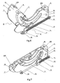
- fig. 8 and fig. 9 present a view of a hinge with a balancing system in the open and closed positions of the sash - in the third embodiment.
- a hinge for a roof window with a pivot sash comprises a hinge part A, secured to the side member of a window frame and a hinge part B secured to the side member of a sash frame. Both hinge parts have base plates 1A and 1 B with screw holes 2 for fastening screws with additional fastening members 3 on one surface.
- the base plate 1A has an arch-bent guide 4 inside of which a friction spring 5 is secured and a through elongated hole 6 is made in the plate 1A between arched members of the guide 4.
- the base plate 1B has a pivoting hook 7 with an arch-bent arm, a guide pin 8 and a bumper 9 limiting the range of the hook 7 pivoting.
- the arch bent arm of the hook 7 and the guide pin 8 mate the guide 4 and the friction spring 5.
- the base plates 1A and 1B at one end have fasteners 10A and 10B for securing external cover members, at the same time after securing the plate 1A to the side member of a window frame, the fastener 10A is located above the sash rotation axis, whereas after securing the plate 1B to the side member of a sash, the fastener 10A is located below the sash rotation axis.
- the base plate 1A has a holder 11 for a spring 12, whose other end is engaged on a slide 13 located in a hole 6.
- the slide 13 protrudes at both sides of the base plate 1A and mates the guide pin 8, secured to the base plate 1 B, and moving along the guide 4.
- the slide 13 is drawn by the spring 12 towards the holder 11.
- the guide pin 8 is guided into the guide 4 and exerts pressure on the slide 13, moving it away from the holder 11 to the other end of the hole 6 when the window sash is closed.
- the spring 12 is than extended but the sash stays in the position set by a user thanks to the friction spring 5, which stops the self-movement of the arm of the hook 7 and the guide pin 8 inside the guide 4.
- a window handle fully protects against the uncontrolled movement of the window sash and blocks the window against opening.
- the spring 12 balances the weight of the window sash and a user only needs to use little power enforcing sash pivoting to turn the window sash.
- a hinge for a roof window with a pivot sash comprises a hinge part A, secured to the side member of a window frame and a hinge part B secured to the side member of a sash frame. Both hinge parts have base plates 1A and 1 B with screw holes 2 for fastening screws with additional fastening members 3 on one surface.
- the base plate 1A has an arch-bent guide 4 inside of which a friction spring 5 is secured and a through, elongated recess 6 is made in the plate 1A between arched members of the guide 4.
- the base plate 1B has a pivoting hook 7 with an arch-bent arm, a guide pin 8, which protrudes beyond the base plate 1A through the recess 6, and a bumper 9 limiting the range of hook 7 pivoting.
- the arched arm of the hook 7 and the guide pin 8 mate the guide 4 and the friction spring 5.
- the base plates 1A and 1B at one end have fasteners 10A and 10B for securing external cover members, at the same time after securing the plate 1A to the side member of a window frame, the fastener 10A is located above the sash rotation axis, whereas after securing the plate 1 B to the side member of a sash, the fastener 10A is located below the sash rotation axis.
- the base plate 1A has two holders 11 and 14 located near the bottom edge of the base plate 1A, where a rod 15 is held with a spiral spring 12 and a slide 13.
- the spring 12 rests with one end against the holder 11 and with the other one it rests against the slide 13.
- the slide 13 is secured to the pivoting catch 16 mating the guide pin 8.
- the catch 16 is fitted with a protrusion 17, which limits its pivoting movement at one side.
- the slide 13 When a window sash is taken out of a window frame or when it is open and turned to the maximum, the slide 13 is located near the holder 14, and the catch 16 rests with the protrusion 17 against the slide 13 in a position ready to mate the guide pin 8.
- a window handle fully protects against uncontrolled pivoting of a window sash and blocks a window against opening.
- the spring 12 balances the weight of the window sash in any position and the window sash stays in a position set by a user thanks to the friction spring 5 while a user only needs to use little power enforcing sash pivoting to turn the window sash.
- a hinge for a roof window with a pivot sash comprises a hinge part A, secured to the side member of a window frame and a hinge part B secured to the side member of a sash frame. Both hinge parts have base plates 1A and 1B with screw holes 2 for fastening screws with additional fastening members 3 on one surface.
- the base plate 1A has an arch-bent guide 4 inside of which a friction spring 5 is mounted and a through, elongated recess 6 is made in the plate 1A between arched members of the guide 4.
- the base plate 1 B has a pivoting hook 7 with an arch-bent arm, a guide pin 8, which protrudes beyond the base plate 1A through the recess 6, and a bumper 9 limiting the range of hook 7 pivoting.
- the arched arm of the hook 7 and the guide pin 8 mate the guide 4 and the friction spring 5.
- the base plates 1A and 1 B at one end have fasteners 10A and 10B for securing external cover members, at the same time after securing the plate 1A to the side member of a window frame, the fastener 10A is located above the sash rotation axis, whereas after securing the plate 1 B to the side member of a sash, the fastener 10A is located below the rotation sash axis.
- the base plate 1A has a guide 18 mounted along the bottom edge of the base plate 1A, restricted at one end by the holder 11.
- the slide 13 in the form of a rod 13' moves along the guide 18.
- the rod 13' is secured with one end to a seat 13" while its other end slides through a hole in the holder 11.
- a spiral spring 12 is slid over the rod 13', one side of the spring 12 is engaged at the free end of the rod 13' and its other side rests against the holder 11.
- the seat 13" is connected to a pivoting catch 16 mating the guide pin 8. Pivoting of the catch 16 is limited at one side by a cut-out in the seat 13".
- the seat 13 When a window sash is taken out of a window frame or when it is open and turned to the maximum, the seat 13 is located near the holder 11, and the catch 16 assumes the position ready to mate the guide pin 8.
- a window handle fully protects against the uncontrolled pivoting of a window sash and blocks the window against opening.
- the spring 12 by means of the catch 16 balances the window sash, which stays in any position set by a user thanks to the friction spring 5 stopping the movement of the pin 8 and the arm of the hook 7 while a user only needs to use little power enforcing sash pivoting to turn the window sash.
Landscapes
- Engineering & Computer Science (AREA)
- Mechanical Engineering (AREA)
- Structural Engineering (AREA)
- Closing And Opening Devices For Wings, And Checks For Wings (AREA)
- Wing Frames And Configurations (AREA)
- Window Of Vehicle (AREA)
Abstract
Description
- The present invention concerns a hinge for a roof window with a sash pivoting around an axis located between the upper and the lower member of a window.
- A roof window with a pivot function is at both sides equipped with pivot hinges, comprising two hinge parts, one hinge part secured to the side member of a window frame, and the other hinge part secured to the side member of a sash. Each hinge part has a base plate for securement by fastening screws through screw holes.
- One side of each base plate has additional means for securing the plate to a window frame or a sash and the other side of the base plate has members mating one another, which connect both plates, enabling their separation, and enable pivoting of the base plates relative to each other. The members constitute: an arched, one-sided open guide with a friction spring located on the base plate secured to a window frame, and a pivoting hook with an arch-bent arm, a guide pin and a bumper for limiting hook pivoting located on the base plate secured to a sash, at the same time the arm-bent hook arm and the guide pin mate the arched guide and the friction spring.
- Pivot hinges in roof windows are secured between the upper and the lower window member, usually in a place that ensures the balance of a sash in the open position of a window. The balance is achieved when the centre of gravity of a window sash is in its rotation axis or in such a distance from the rotation axis that the hinge friction spring is able to keep an unbalanced sash in any rotational position. Therefore the rotation axis of a roof window sash is usually located at a little distance from the half of the window height. A bigger shift of the sash rotation axis or any additional equipment on any of its parts, the lower or the upper, disturbs the balance and causes that a window is unable to hold its sash in each ajar position and a user operating the window has to use more strength to overcome the unbalanced weight of the sash.
- A roof pivot window is known from application
WO2005/019575 disclosing the features of the preamble of claim 1 and which is equipped with a known pivot hinge, of the rotation axis located in the upper half of a window sash, in addition it is equipped with at least one auxiliary device independent from the hinge, presented as a cylinder, which carries the lower, heavier part of a window sash. The device is at one end secured to a window frame and at the other end it is secured to a window sash, in addition the securement allows to separate the device from the window frame. - The auxiliary device constitutes an additional fixture of a roof window and it requires performing of additional activities during assembly of a window and during installation of a window in a roof, it deteriorates aesthetics of the window in an ajar position of the sash, moreover if the need arises to remove a sash from a window frame the cylinder must be disconnected from the window frame beforehand.
- The object of the present invention is a pivot hinge with a balancing system for roof windows with a sash pivoting around the axis located between the upper and lower member of a window, which ensures the state of equilibrium of a window sash when its centre of gravity is located beyond the sash rotating axis and the friction spring of the hinge is unable to hold the sash pivoted in each its position. At the same the time the window fittings, its assembly and installation in a roof as well as its appearance remain unchanged. Also the method of separating both hinge parts - taking a sash out of a window frame - remains unchanged.
- A hinge for roof windows, according to the present invention defined by the features of claim 1, is presented in embodiment examples on a drawing where
fig. 1 and fig. 2 present a view of a hinge with a balancing system in the open and closed positions of a sash - in the first embodiment;fig. 3 shows the surface of the hinge base plate B mating the plate A - suitable for all embodiments described and presented in the drawings;fig. 4 shows the hinge base plate A viewed from the side mating the plate B, in the first embodiment;fig. 5 shows the hinge base plate A viewed from the side of the mating surfaces in the second and the third embodiment;fig. 6 and fig.7 present a view of a hinge with a balancing system in the open and closed positions of a sash - in the second embodiment;fig. 8 and fig. 9 present a view of a hinge with a balancing system in the open and closed positions of the sash - in the third embodiment. - A hinge for a roof window with a pivot sash comprises a hinge part A, secured to the side member of a window frame and a hinge part B secured to the side member of a sash frame. Both hinge parts have
base plates screw holes 2 for fastening screws withadditional fastening members 3 on one surface. At the other surface thebase plate 1A has an arch-bent guide 4 inside of which afriction spring 5 is secured and a throughelongated hole 6 is made in theplate 1A between arched members of the guide 4. Thebase plate 1B has apivoting hook 7 with an arch-bent arm, a guide pin 8 and abumper 9 limiting the range of thehook 7 pivoting. The arch bent arm of thehook 7 and the guide pin 8 mate the guide 4 and thefriction spring 5. - The
base plates fasteners plate 1A to the side member of a window frame, thefastener 10A is located above the sash rotation axis, whereas after securing theplate 1B to the side member of a sash, thefastener 10A is located below the sash rotation axis. - At the side with the fastening
member 3 thebase plate 1A has aholder 11 for aspring 12, whose other end is engaged on aslide 13 located in ahole 6. - The
slide 13 protrudes at both sides of thebase plate 1A and mates the guide pin 8, secured to thebase plate 1 B, and moving along the guide 4. - When a window sash is taken out of a window frame or it is pivoted to the maximum, the
slide 13 is drawn by thespring 12 towards theholder 11. During mounting a window sash in a window frame and during closing a window sash the guide pin 8 is guided into the guide 4 and exerts pressure on theslide 13, moving it away from theholder 11 to the other end of thehole 6 when the window sash is closed. Thespring 12 is than extended but the sash stays in the position set by a user thanks to thefriction spring 5, which stops the self-movement of the arm of thehook 7 and the guide pin 8 inside the guide 4. - Turning a window handle fully protects against the uncontrolled movement of the window sash and blocks the window against opening. After realising the lock with a window handle the
spring 12 balances the weight of the window sash and a user only needs to use little power enforcing sash pivoting to turn the window sash. - A hinge for a roof window with a pivot sash comprises a hinge part A, secured to the side member of a window frame and a hinge part B secured to the side member of a sash frame. Both hinge parts have
base plates screw holes 2 for fastening screws withadditional fastening members 3 on one surface. At the other surface thebase plate 1A has an arch-bent guide 4 inside of which afriction spring 5 is secured and a through,elongated recess 6 is made in theplate 1A between arched members of the guide 4. Thebase plate 1B has apivoting hook 7 with an arch-bent arm, a guide pin 8, which protrudes beyond thebase plate 1A through therecess 6, and abumper 9 limiting the range ofhook 7 pivoting. The arched arm of thehook 7 and the guide pin 8 mate the guide 4 and thefriction spring 5. - The
base plates fasteners plate 1A to the side member of a window frame, thefastener 10A is located above the sash rotation axis, whereas after securing theplate 1 B to the side member of a sash, thefastener 10A is located below the sash rotation axis. - At the side with the
fastening member 3 thebase plate 1A has twoholders base plate 1A, where arod 15 is held with aspiral spring 12 and aslide 13. Thespring 12 rests with one end against theholder 11 and with the other one it rests against theslide 13. Theslide 13 is secured to thepivoting catch 16 mating the guide pin 8. Thecatch 16 is fitted with aprotrusion 17, which limits its pivoting movement at one side. - When a window sash is taken out of a window frame or when it is open and turned to the maximum, the
slide 13 is located near theholder 14, and thecatch 16 rests with theprotrusion 17 against theslide 13 in a position ready to mate the guide pin 8. - During mounting of a window sash in a window frame and during closing a window the guide pin 8 together with the arched arm of the
hook 7 is guided into the guide 4 and therecess 6 and slides into thecatch 16. During the further movement of the window sash the guide pin 8 slides inside the guide 4 and pulls thecatch 16 together with theslide 13 towards theholder 11 and makes thespring 12 compressed. Thespring 12 by means of thecatch 16 balances the window sash, which stays in any position set by a user thanks to thefriction spring 5, stopping the movement of the pin 8 and thehook 7. - Turning a window handle fully protects against uncontrolled pivoting of a window sash and blocks a window against opening. After realising the lock with a window handle the
spring 12 balances the weight of the window sash in any position and the window sash stays in a position set by a user thanks to thefriction spring 5 while a user only needs to use little power enforcing sash pivoting to turn the window sash. - A hinge for a roof window with a pivot sash comprises a hinge part A, secured to the side member of a window frame and a hinge part B secured to the side member of a sash frame. Both hinge parts have
base plates screw holes 2 for fastening screws withadditional fastening members 3 on one surface. At the other surface thebase plate 1A has an arch-bent guide 4 inside of which afriction spring 5 is mounted and a through,elongated recess 6 is made in theplate 1A between arched members of the guide 4. Thebase plate 1 B has apivoting hook 7 with an arch-bent arm, a guide pin 8, which protrudes beyond thebase plate 1A through therecess 6, and abumper 9 limiting the range ofhook 7 pivoting. The arched arm of thehook 7 and the guide pin 8 mate the guide 4 and thefriction spring 5. - The
base plates fasteners plate 1A to the side member of a window frame, thefastener 10A is located above the sash rotation axis, whereas after securing theplate 1 B to the side member of a sash, thefastener 10A is located below the rotation sash axis. - At the side with the
fastening member 3 thebase plate 1A has aguide 18 mounted along the bottom edge of thebase plate 1A, restricted at one end by theholder 11. Theslide 13 in the form of a rod 13' moves along theguide 18. The rod 13' is secured with one end to aseat 13" while its other end slides through a hole in theholder 11. Aspiral spring 12 is slid over the rod 13', one side of thespring 12 is engaged at the free end of the rod 13' and its other side rests against theholder 11. Theseat 13" is connected to apivoting catch 16 mating the guide pin 8. Pivoting of thecatch 16 is limited at one side by a cut-out in theseat 13". - When a window sash is taken out of a window frame or when it is open and turned to the maximum, the
seat 13 is located near theholder 11, and thecatch 16 assumes the position ready to mate the guide pin 8. - During mounting of a window sash in a window frame or during closing a window the guide pin 8 inserted into the guide 4 and the
recess 6 slides into thecatch 16. During a further movement of the window sash the guide pin 8 slides inside the guide 4 and moves thecatch 16 together with theslide 13 away from theholder 11 and enforces compression of thespring 12. - Turning of a window handle fully protects against the uncontrolled pivoting of a window sash and blocks the window against opening. After realising the lock with a window handle the
spring 12 by means of thecatch 16 balances the window sash, which stays in any position set by a user thanks to thefriction spring 5 stopping the movement of the pin 8 and the arm of thehook 7 while a user only needs to use little power enforcing sash pivoting to turn the window sash.
Claims (7)
- Hinge for a roof window with a pivot sash comprising two hinge parts, each hinge part has a base plate with means enabling to secure a base plate to the side surface of the side member of a window, at the same time the base plate secured to a window frame has at one side an arched-bent guide and the base plate secured to a window sash has at one side a pivoting hook member with an arch bent arm and a guide pin, mating the arched guide, and a bumper limiting the range of hook member pivoting, moreover the hinge is equipped with a braking frictional member, which keeps the sash in a fixed position, characterized in that in the base plate (1A), between the arched members of the guide (4), a through, elongated recess (6) is located, and at the opposite side to the arched guide (4) on the plate (1A) a system balancing the window sash is mounted, which mates the guide pin (8) mounted on the hinge base plate (1 B), in addition the hinge has the existing, unchanged method of separating the plates (A) and (B) from each other.
- Hinge as claimed in claim 1, characterized in that the system balancing the window sash comprises a spring (12) and a slide (13), mounted on the base plate (1A) at the same time the slide (13) mates the guide pin (8).
- Hinge as claimed in claim 2, characterized in that the slide (13) is located in a longitudinal hole (6), between the arched members of the guide (4) and protrudes at both sides of the plate (1A).
- Hinge as claimed in claim 2, characterized in that the guide pin (8), mounted on the base plate (1 B), protrudes through the recess (6) beyond the base plate (1A), and the slide (13) is secured to the catch (16), mating the guide pin (8).
- Hinge as claimed in claim 4, characterized in that along the bottom edge of the plate (1A), at the opposite side to the arched guide (4), the rod (15) with the slide (13) and the spring (12) are mounted in holders (11) and (14), at the same time the spring (12) is placed between the holder (11) and the slide (13).
- Hinge as claimed in claim 4, characterized in that along the bottom edge of the plate (1A), at the opposite side to the arched guide (4), the guide (18) is mounted, which mates the slide (13), consisting of the rod (13') secured with one end to the seat (13"), whereas the other end of the rod (13') slides through a hole in the holder (11), and the spring (12) slid over the rod (13') is spaced between the holder (11) and the free end of the rod (13').
- Hinge as claimed in claim 4 or 5 or 6, characterized in that the catch (16) always assumes the position ready to mate the guide pin (8) thanks to the means limiting its pivoting movement.
Applications Claiming Priority (2)
| Application Number | Priority Date | Filing Date | Title |
|---|---|---|---|
| PL380795A PL212774B1 (en) | 2006-10-09 | 2006-10-09 | Hinge of a roof window with rotating wing |
| PCT/PL2007/000068 WO2008044953A1 (en) | 2006-10-09 | 2007-10-09 | Hinge for a roof window with a pivot sash |
Publications (2)
| Publication Number | Publication Date |
|---|---|
| EP2084357A1 EP2084357A1 (en) | 2009-08-05 |
| EP2084357B1 true EP2084357B1 (en) | 2010-03-03 |
Family
ID=38935799
Family Applications (1)
| Application Number | Title | Priority Date | Filing Date |
|---|---|---|---|
| EP07834896A Active EP2084357B1 (en) | 2006-10-09 | 2007-10-09 | Hinge for a roof window with a pivot sash |
Country Status (7)
| Country | Link |
|---|---|
| US (1) | US8108971B2 (en) |
| EP (1) | EP2084357B1 (en) |
| CN (1) | CN101605958A (en) |
| AT (1) | ATE459775T1 (en) |
| DE (1) | DE602007005164D1 (en) |
| PL (1) | PL212774B1 (en) |
| WO (1) | WO2008044953A1 (en) |
Families Citing this family (21)
| Publication number | Priority date | Publication date | Assignee | Title |
|---|---|---|---|---|
| GB0907951D0 (en) * | 2009-05-08 | 2009-06-24 | Keystone Lintels Ltd | A fixture for a window |
| DE102010029065B4 (en) * | 2010-05-18 | 2023-10-26 | Ford Global Technologies, Llc | Door edge protection device |
| US9151099B2 (en) * | 2011-11-03 | 2015-10-06 | Savannah River Nuclear Solutions, Llc | Egress door opening assister |
| US9451718B2 (en) | 2014-06-30 | 2016-09-20 | Eaton Corporation | Telescoping panels suitable for motor control center units and related motor control centers |
| US9531169B2 (en) | 2014-06-30 | 2016-12-27 | Eaton Corporation | Motor control center units with retractable stabs and interlocks using portal shutters |
| CN104196384A (en) * | 2014-08-08 | 2014-12-10 | 苏州奥林五金有限公司 | Rainproof type hinge |
| TWI549594B (en) * | 2014-09-18 | 2016-09-11 | 宏碁股份有限公司 | Hinge structure |
| TWM514390U (en) * | 2014-11-26 | 2015-12-21 | Concraft Holding Co Ltd | Jig structure capable of changing direction |
| US9366064B1 (en) * | 2015-05-29 | 2016-06-14 | Lianhong Art Co., Ltd. | Hinge structure |
| DK179269B1 (en) * | 2015-11-06 | 2018-03-19 | Vkr Holding As | A hinge for a roof window, and a roof window including a set of such hinges |
| TWI598022B (en) * | 2015-11-16 | 2017-09-01 | Compal Electronics Inc | Electronic Device and Hinge Thereof |
| US9637963B1 (en) * | 2016-04-11 | 2017-05-02 | Emily Patricia Heichel | Hinged connector device |
| EP3323968B1 (en) * | 2016-11-18 | 2021-03-03 | VKR Holding A/S | A hinge arrangement of a roof window with improved operability |
| US10186847B2 (en) | 2016-11-21 | 2019-01-22 | Eaton Intelligent Power Limited | Motor control center (MCC) units with slidable shutters |
| US10211606B2 (en) | 2016-11-29 | 2019-02-19 | Eaton Intelligent Power Limited | Motor control center units with multi-purpose shutter cams and related units |
| US11028627B2 (en) * | 2017-05-05 | 2021-06-08 | Vkr Holding A/S | Hinge for a window, a window including a set of such hinges, and a method of installing such a window |
| US10221596B1 (en) * | 2017-10-17 | 2019-03-05 | GM Global Technology Operations LLC | Telescopic trunk lid support device |
| US10742004B2 (en) | 2017-12-20 | 2020-08-11 | Eaton Intelligent Power Limited | Motor control center (MCC) units with retractable power connector and interlocks including a power connector position interlock |
| ES2724126B2 (en) * | 2018-03-02 | 2020-05-06 | Eidopia S L | Mechanical articulation system using an invisible and adjustable kneecap. |
| CA3073017A1 (en) | 2019-02-22 | 2020-08-22 | Eaton Intelligent Power Limited | Motor control center (mcc) units with dual disconnect switches, dual operator handles, retractable power connector and interlocks |
| US11072952B2 (en) * | 2019-03-06 | 2021-07-27 | Bsh Home Appliances Corporation | Side opening door keeper |
Family Cites Families (11)
| Publication number | Priority date | Publication date | Assignee | Title |
|---|---|---|---|---|
| US4796331A (en) * | 1987-12-30 | 1989-01-10 | Gkn Crompton Limited | Hinge for roof window |
| ZA913196B (en) * | 1990-04-30 | 1992-12-30 | Charles Sandell Anthony | Hinge for use in a roof assembly |
| DE9406930U1 (en) * | 1994-04-26 | 1994-07-07 | Roto Frank Ag, 70771 Leinfelden-Echterdingen | Folding swing roof window |
| DE9406929U1 (en) * | 1994-04-26 | 1994-06-16 | Roto Frank Ag, 70771 Leinfelden-Echterdingen | Roof window |
| DK176024B1 (en) | 1997-11-11 | 2005-12-19 | Vkr Holding As | Hinge bracket for a rocker window |
| ATE364768T1 (en) * | 2003-08-20 | 2007-07-15 | Vkr Holding As | IMPROVED TILTING WINDOW WITH LOCKING DEVICE |
| PL1760234T3 (en) * | 2005-09-05 | 2019-04-30 | Vkr Holding As | A pivot hinge and a pivot window |
| PL213375B1 (en) * | 2006-07-19 | 2013-02-28 | Fakro Pp Spolka Z Ograniczona Odpowiedzialnoscia | Hinge for pivoting roof light |
| PL215150B1 (en) * | 2006-07-24 | 2013-10-31 | Fakro Pp Spolka Z Ograniczona Odpowiedzialnoscia | Hinge for pivoting roof light and method for mounting the hinge in pivoting roof light, particularly with frame made of multi-chamber plastic sections |
| WO2010003411A1 (en) * | 2008-07-10 | 2010-01-14 | Vkr Holding A/S | A pivot window with electrical hinge connection |
| PL219926B1 (en) * | 2008-07-11 | 2015-08-31 | Fakro Pp Spółka Z Ograniczoną Odpowiedzialnością | Swing hinge for a roof window and its attachement unit, in particular for a roof window |
-
2006
- 2006-10-09 PL PL380795A patent/PL212774B1/en unknown
-
2007
- 2007-10-09 DE DE602007005164T patent/DE602007005164D1/en active Active
- 2007-10-09 US US12/443,115 patent/US8108971B2/en not_active Expired - Fee Related
- 2007-10-09 CN CNA2007800423752A patent/CN101605958A/en active Pending
- 2007-10-09 WO PCT/PL2007/000068 patent/WO2008044953A1/en active Application Filing
- 2007-10-09 AT AT07834896T patent/ATE459775T1/en not_active IP Right Cessation
- 2007-10-09 EP EP07834896A patent/EP2084357B1/en active Active
Also Published As
| Publication number | Publication date |
|---|---|
| US20100071163A1 (en) | 2010-03-25 |
| EP2084357A1 (en) | 2009-08-05 |
| PL212774B1 (en) | 2012-11-30 |
| US8108971B2 (en) | 2012-02-07 |
| WO2008044953A1 (en) | 2008-04-17 |
| CN101605958A (en) | 2009-12-16 |
| ATE459775T1 (en) | 2010-03-15 |
| DE602007005164D1 (en) | 2010-04-15 |
| PL380795A1 (en) | 2008-04-14 |
Similar Documents
| Publication | Publication Date | Title |
|---|---|---|
| EP2084357B1 (en) | Hinge for a roof window with a pivot sash | |
| CA2560394C (en) | Damping device for furniture hinges | |
| CA2659885C (en) | Wall panel system including a retractable floor anchor and method | |
| PL1966458T3 (en) | Door hinge device with fulcrum at variable position | |
| EP1741860A1 (en) | Snap hinge for supporting a closure element | |
| US9790718B2 (en) | Door hinge | |
| WO2006120105A3 (en) | Hinge for pivotally moving a laterally opening door | |
| CN219299038U (en) | American damping hinge capable of being quickly disassembled and assembled | |
| FR2890386B1 (en) | CARRIER CARRIER HAVING DOUBLE HINGED DOOR TRANSMITTING EFFORT | |
| CA2697880A1 (en) | Adjustable hinge | |
| EP1899563A2 (en) | Sash hinge | |
| CN113195906B (en) | Furniture drive | |
| CN115977483A (en) | American damping hinge capable of being quickly disassembled and assembled | |
| CA2856577C (en) | Bracket door closurer | |
| CN210396456U (en) | Multifunctional hidden door and window hinge | |
| US5095583A (en) | Folding-arm bearing for an oscillating-swinging leaf | |
| CN209556694U (en) | A kind of New type hinge | |
| EP2959085A1 (en) | Damped hinge assemblies | |
| US7213850B1 (en) | Door knob holder | |
| CN205400354U (en) | Door and window hinge | |
| KR100770425B1 (en) | Damping device for furniture hinges | |
| CN214414322U (en) | Draw-bar box | |
| CN214740658U (en) | Mute load-bearing type sliding support hinge | |
| EP2218855A2 (en) | Glass door hinge | |
| CN210105573U (en) | Three-dimensional adjustable hinge |
Legal Events
| Date | Code | Title | Description |
|---|---|---|---|
| PUAI | Public reference made under article 153(3) epc to a published international application that has entered the european phase |
Free format text: ORIGINAL CODE: 0009012 |
|
| 17P | Request for examination filed |
Effective date: 20090506 |
|
| AK | Designated contracting states |
Kind code of ref document: A1 Designated state(s): AT BE BG CH CY CZ DE DK EE ES FI FR GB GR HU IE IS IT LI LT LU LV MC MT NL PL PT RO SE SI SK TR |
|
| GRAP | Despatch of communication of intention to grant a patent |
Free format text: ORIGINAL CODE: EPIDOSNIGR1 |
|
| DAX | Request for extension of the european patent (deleted) | ||
| GRAS | Grant fee paid |
Free format text: ORIGINAL CODE: EPIDOSNIGR3 |
|
| GRAA | (expected) grant |
Free format text: ORIGINAL CODE: 0009210 |
|
| AK | Designated contracting states |
Kind code of ref document: B1 Designated state(s): AT BE BG CH CY CZ DE DK EE ES FI FR GB GR HU IE IS IT LI LT LU LV MC MT NL PL PT RO SE SI SK TR |
|
| REG | Reference to a national code |
Ref country code: GB Ref legal event code: FG4D |
|
| REG | Reference to a national code |
Ref country code: CH Ref legal event code: EP |
|
| REG | Reference to a national code |
Ref country code: IE Ref legal event code: FG4D |
|
| REF | Corresponds to: |
Ref document number: 602007005164 Country of ref document: DE Date of ref document: 20100415 Kind code of ref document: P |
|
| REG | Reference to a national code |
Ref country code: NL Ref legal event code: VDEP Effective date: 20100303 |
|
| PG25 | Lapsed in a contracting state [announced via postgrant information from national office to epo] |
Ref country code: LT Free format text: LAPSE BECAUSE OF FAILURE TO SUBMIT A TRANSLATION OF THE DESCRIPTION OR TO PAY THE FEE WITHIN THE PRESCRIBED TIME-LIMIT Effective date: 20100303 |
|
| LTIE | Lt: invalidation of european patent or patent extension |
Effective date: 20100303 |
|
| PG25 | Lapsed in a contracting state [announced via postgrant information from national office to epo] |
Ref country code: SI Free format text: LAPSE BECAUSE OF FAILURE TO SUBMIT A TRANSLATION OF THE DESCRIPTION OR TO PAY THE FEE WITHIN THE PRESCRIBED TIME-LIMIT Effective date: 20100303 Ref country code: PL Free format text: LAPSE BECAUSE OF FAILURE TO SUBMIT A TRANSLATION OF THE DESCRIPTION OR TO PAY THE FEE WITHIN THE PRESCRIBED TIME-LIMIT Effective date: 20100303 Ref country code: LV Free format text: LAPSE BECAUSE OF FAILURE TO SUBMIT A TRANSLATION OF THE DESCRIPTION OR TO PAY THE FEE WITHIN THE PRESCRIBED TIME-LIMIT Effective date: 20100303 Ref country code: FI Free format text: LAPSE BECAUSE OF FAILURE TO SUBMIT A TRANSLATION OF THE DESCRIPTION OR TO PAY THE FEE WITHIN THE PRESCRIBED TIME-LIMIT Effective date: 20100303 Ref country code: AT Free format text: LAPSE BECAUSE OF FAILURE TO SUBMIT A TRANSLATION OF THE DESCRIPTION OR TO PAY THE FEE WITHIN THE PRESCRIBED TIME-LIMIT Effective date: 20100303 |
|
| PG25 | Lapsed in a contracting state [announced via postgrant information from national office to epo] |
Ref country code: EE Free format text: LAPSE BECAUSE OF FAILURE TO SUBMIT A TRANSLATION OF THE DESCRIPTION OR TO PAY THE FEE WITHIN THE PRESCRIBED TIME-LIMIT Effective date: 20100303 Ref country code: CY Free format text: LAPSE BECAUSE OF FAILURE TO SUBMIT A TRANSLATION OF THE DESCRIPTION OR TO PAY THE FEE WITHIN THE PRESCRIBED TIME-LIMIT Effective date: 20100303 Ref country code: BE Free format text: LAPSE BECAUSE OF FAILURE TO SUBMIT A TRANSLATION OF THE DESCRIPTION OR TO PAY THE FEE WITHIN THE PRESCRIBED TIME-LIMIT Effective date: 20100303 Ref country code: RO Free format text: LAPSE BECAUSE OF FAILURE TO SUBMIT A TRANSLATION OF THE DESCRIPTION OR TO PAY THE FEE WITHIN THE PRESCRIBED TIME-LIMIT Effective date: 20100303 Ref country code: GR Free format text: LAPSE BECAUSE OF FAILURE TO SUBMIT A TRANSLATION OF THE DESCRIPTION OR TO PAY THE FEE WITHIN THE PRESCRIBED TIME-LIMIT Effective date: 20100604 Ref country code: ES Free format text: LAPSE BECAUSE OF FAILURE TO SUBMIT A TRANSLATION OF THE DESCRIPTION OR TO PAY THE FEE WITHIN THE PRESCRIBED TIME-LIMIT Effective date: 20100614 Ref country code: SE Free format text: LAPSE BECAUSE OF FAILURE TO SUBMIT A TRANSLATION OF THE DESCRIPTION OR TO PAY THE FEE WITHIN THE PRESCRIBED TIME-LIMIT Effective date: 20100303 Ref country code: NL Free format text: LAPSE BECAUSE OF FAILURE TO SUBMIT A TRANSLATION OF THE DESCRIPTION OR TO PAY THE FEE WITHIN THE PRESCRIBED TIME-LIMIT Effective date: 20100303 |
|
| PG25 | Lapsed in a contracting state [announced via postgrant information from national office to epo] |
Ref country code: CZ Free format text: LAPSE BECAUSE OF FAILURE TO SUBMIT A TRANSLATION OF THE DESCRIPTION OR TO PAY THE FEE WITHIN THE PRESCRIBED TIME-LIMIT Effective date: 20100303 Ref country code: SK Free format text: LAPSE BECAUSE OF FAILURE TO SUBMIT A TRANSLATION OF THE DESCRIPTION OR TO PAY THE FEE WITHIN THE PRESCRIBED TIME-LIMIT Effective date: 20100303 Ref country code: BG Free format text: LAPSE BECAUSE OF FAILURE TO SUBMIT A TRANSLATION OF THE DESCRIPTION OR TO PAY THE FEE WITHIN THE PRESCRIBED TIME-LIMIT Effective date: 20100603 Ref country code: IS Free format text: LAPSE BECAUSE OF FAILURE TO SUBMIT A TRANSLATION OF THE DESCRIPTION OR TO PAY THE FEE WITHIN THE PRESCRIBED TIME-LIMIT Effective date: 20100703 |
|
| PLBI | Opposition filed |
Free format text: ORIGINAL CODE: 0009260 |
|
| 26 | Opposition filed |
Opponent name: VKR-HOLDING A/S Effective date: 20101202 |
|
| PLAX | Notice of opposition and request to file observation + time limit sent |
Free format text: ORIGINAL CODE: EPIDOSNOBS2 |
|
| PG25 | Lapsed in a contracting state [announced via postgrant information from national office to epo] |
Ref country code: PT Free format text: LAPSE BECAUSE OF FAILURE TO SUBMIT A TRANSLATION OF THE DESCRIPTION OR TO PAY THE FEE WITHIN THE PRESCRIBED TIME-LIMIT Effective date: 20100705 Ref country code: DK Free format text: LAPSE BECAUSE OF FAILURE TO SUBMIT A TRANSLATION OF THE DESCRIPTION OR TO PAY THE FEE WITHIN THE PRESCRIBED TIME-LIMIT Effective date: 20100303 |
|
| PG25 | Lapsed in a contracting state [announced via postgrant information from national office to epo] |
Ref country code: IT Free format text: LAPSE BECAUSE OF FAILURE TO SUBMIT A TRANSLATION OF THE DESCRIPTION OR TO PAY THE FEE WITHIN THE PRESCRIBED TIME-LIMIT Effective date: 20100303 |
|
| PG25 | Lapsed in a contracting state [announced via postgrant information from national office to epo] |
Ref country code: MC Free format text: LAPSE BECAUSE OF NON-PAYMENT OF DUE FEES Effective date: 20101031 |
|
| PLBB | Reply of patent proprietor to notice(s) of opposition received |
Free format text: ORIGINAL CODE: EPIDOSNOBS3 |
|
| PG25 | Lapsed in a contracting state [announced via postgrant information from national office to epo] |
Ref country code: IE Free format text: LAPSE BECAUSE OF NON-PAYMENT OF DUE FEES Effective date: 20101009 |
|
| PG25 | Lapsed in a contracting state [announced via postgrant information from national office to epo] |
Ref country code: MT Free format text: LAPSE BECAUSE OF FAILURE TO SUBMIT A TRANSLATION OF THE DESCRIPTION OR TO PAY THE FEE WITHIN THE PRESCRIBED TIME-LIMIT Effective date: 20100303 |
|
| REG | Reference to a national code |
Ref country code: CH Ref legal event code: PL |
|
| PG25 | Lapsed in a contracting state [announced via postgrant information from national office to epo] |
Ref country code: CH Free format text: LAPSE BECAUSE OF NON-PAYMENT OF DUE FEES Effective date: 20111031 Ref country code: LI Free format text: LAPSE BECAUSE OF NON-PAYMENT OF DUE FEES Effective date: 20111031 |
|
| PG25 | Lapsed in a contracting state [announced via postgrant information from national office to epo] |
Ref country code: LU Free format text: LAPSE BECAUSE OF NON-PAYMENT OF DUE FEES Effective date: 20101009 Ref country code: HU Free format text: LAPSE BECAUSE OF FAILURE TO SUBMIT A TRANSLATION OF THE DESCRIPTION OR TO PAY THE FEE WITHIN THE PRESCRIBED TIME-LIMIT Effective date: 20100904 |
|
| PG25 | Lapsed in a contracting state [announced via postgrant information from national office to epo] |
Ref country code: TR Free format text: LAPSE BECAUSE OF FAILURE TO SUBMIT A TRANSLATION OF THE DESCRIPTION OR TO PAY THE FEE WITHIN THE PRESCRIBED TIME-LIMIT Effective date: 20100303 |
|
| PGFP | Annual fee paid to national office [announced via postgrant information from national office to epo] |
Ref country code: FR Payment date: 20131022 Year of fee payment: 7 |
|
| REG | Reference to a national code |
Ref country code: DE Ref legal event code: R100 Ref document number: 602007005164 Country of ref document: DE |
|
| PLCK | Communication despatched that opposition was rejected |
Free format text: ORIGINAL CODE: EPIDOSNREJ1 |
|
| PLBN | Opposition rejected |
Free format text: ORIGINAL CODE: 0009273 |
|
| STAA | Information on the status of an ep patent application or granted ep patent |
Free format text: STATUS: OPPOSITION REJECTED |
|
| 27O | Opposition rejected |
Effective date: 20140925 |
|
| REG | Reference to a national code |
Ref country code: DE Ref legal event code: R100 Ref document number: 602007005164 Country of ref document: DE Effective date: 20140925 |
|
| REG | Reference to a national code |
Ref country code: FR Ref legal event code: ST Effective date: 20150630 |
|
| PG25 | Lapsed in a contracting state [announced via postgrant information from national office to epo] |
Ref country code: FR Free format text: LAPSE BECAUSE OF NON-PAYMENT OF DUE FEES Effective date: 20141031 |
|
| REG | Reference to a national code |
Ref country code: DE Ref legal event code: R119 Ref document number: 602007005164 Country of ref document: DE Ref country code: DE Ref legal event code: R409 Ref document number: 602007005164 Country of ref document: DE |
|
| PG25 | Lapsed in a contracting state [announced via postgrant information from national office to epo] |
Ref country code: DE Free format text: LAPSE BECAUSE OF NON-PAYMENT OF DUE FEES Effective date: 20190501 |
|
| PG25 | Lapsed in a contracting state [announced via postgrant information from national office to epo] |
Ref country code: DE Free format text: LAPSE BECAUSE OF NON-PAYMENT OF DUE FEES Effective date: 20190501 |
|
| PGRI | Patent reinstated in contracting state [announced from national office to epo] |
Ref country code: DE Effective date: 20200311 |
|
| P01 | Opt-out of the competence of the unified patent court (upc) registered |
Effective date: 20230419 |
|
| PGFP | Annual fee paid to national office [announced via postgrant information from national office to epo] |
Ref country code: GB Payment date: 20230913 Year of fee payment: 17 |
|
| PGFP | Annual fee paid to national office [announced via postgrant information from national office to epo] |
Ref country code: DE Payment date: 20230913 Year of fee payment: 17 |