EP2083218A2 - Système de cheminée - Google Patents
Système de cheminée Download PDFInfo
- Publication number
- EP2083218A2 EP2083218A2 EP09000875A EP09000875A EP2083218A2 EP 2083218 A2 EP2083218 A2 EP 2083218A2 EP 09000875 A EP09000875 A EP 09000875A EP 09000875 A EP09000875 A EP 09000875A EP 2083218 A2 EP2083218 A2 EP 2083218A2
- Authority
- EP
- European Patent Office
- Prior art keywords
- chimney
- pipe
- chimney pipe
- fresh air
- combustion gases
- Prior art date
- Legal status (The legal status is an assumption and is not a legal conclusion. Google has not performed a legal analysis and makes no representation as to the accuracy of the status listed.)
- Withdrawn
Links
Images


Classifications
-
- F—MECHANICAL ENGINEERING; LIGHTING; HEATING; WEAPONS; BLASTING
- F23—COMBUSTION APPARATUS; COMBUSTION PROCESSES
- F23J—REMOVAL OR TREATMENT OF COMBUSTION PRODUCTS OR COMBUSTION RESIDUES; FLUES
- F23J13/00—Fittings for chimneys or flues
- F23J13/02—Linings; Jackets; Casings
- F23J13/025—Linings; Jackets; Casings composed of concentric elements, e.g. double walled
-
- F—MECHANICAL ENGINEERING; LIGHTING; HEATING; WEAPONS; BLASTING
- F23—COMBUSTION APPARATUS; COMBUSTION PROCESSES
- F23J—REMOVAL OR TREATMENT OF COMBUSTION PRODUCTS OR COMBUSTION RESIDUES; FLUES
- F23J2213/00—Chimneys or flues
- F23J2213/10—Linings
- F23J2213/101—Fastening means therefor
-
- F—MECHANICAL ENGINEERING; LIGHTING; HEATING; WEAPONS; BLASTING
- F23—COMBUSTION APPARATUS; COMBUSTION PROCESSES
- F23J—REMOVAL OR TREATMENT OF COMBUSTION PRODUCTS OR COMBUSTION RESIDUES; FLUES
- F23J2213/00—Chimneys or flues
- F23J2213/20—Joints; Connections
- F23J2213/202—Joints; Connections between duct or stack sections
-
- F—MECHANICAL ENGINEERING; LIGHTING; HEATING; WEAPONS; BLASTING
- F23—COMBUSTION APPARATUS; COMBUSTION PROCESSES
- F23J—REMOVAL OR TREATMENT OF COMBUSTION PRODUCTS OR COMBUSTION RESIDUES; FLUES
- F23J2213/00—Chimneys or flues
- F23J2213/30—Specific materials
- F23J2213/302—Specific materials plastic
-
- F—MECHANICAL ENGINEERING; LIGHTING; HEATING; WEAPONS; BLASTING
- F23—COMBUSTION APPARATUS; COMBUSTION PROCESSES
- F23J—REMOVAL OR TREATMENT OF COMBUSTION PRODUCTS OR COMBUSTION RESIDUES; FLUES
- F23J2900/00—Special arrangements for conducting or purifying combustion fumes; Treatment of fumes or ashes
- F23J2900/13004—Water draining devices associated with flues
Definitions
- the invention relates to a fireplace for combustion plants, in particular for gas or oil-fired heating systems.
- hydrocarbons are derived from living matter, they contain a large amount of carbon and in smaller quantities a variety of other substances, such as sulfur and nitrogen.
- the combustion gas therefore contains in addition to water vapor, carbon dioxide, soot, sulfur oxides and nitrogen oxides and sulfuric acid. Most of the nitrogen oxides are nitrogen, which also comes from the combustion air.
- water vapor, soot, sulfur oxides and sulfuric acid can be at least partially retained by suitable means but with high technical and energy expenditure.
- chimneys made of high-quality plastics such as PVDF (polyvinylidene fluoride) are used, which are able to withstand the action of the condensate.
- PVDF polyvinylidene fluoride
- a condensation of the combustion gases is deliberately allowed and thereby recovered a large part of the energy which is bound in the combustion gas.
- condensation chimneys a large part of the pollutants contained in the flue gas, polluting substances such as sulfuric acid, unburned hydrocarbons, water vapor and soot can be retained in the chimney pipe.
- condensation temperature of the boiler can be reduced to a minimum become.
- the temperature of the exhaust gas when leaving the boiler only about 30-40 ° C and in the low-temperature technology about 90-140 ° C amount.
- a reduction of the flue gas temperature means a more efficient use of the heat of combustion for heating the heat carrier (usually water) and a saving of expensive fuel.
- Condensation chimneys allow for the first time to operate the boilers with the minimum boiler water temperature prescribed by the manufacturer, from which then the lowest possible exhaust gas temperature and from that again the highest possible efficiency of the combustion plant results.
- the thus preheated fresh combustion air is then used to operate the boiler and thus reused the heat of the combustion gases.
- the DE 3421 112 A1 describes a condensation chimney, which is used for the application of the technique of cold, wet, condensing chimney.
- This fireplace is most effective in terms of heat recovery and combustion gas purification in heating systems for smaller buildings.
- the efficiency of this condensation chimney is not optimal.
- heating systems are operated intermittently even in Kondensationskaminen, i. During the course of a day, the burner of the boiler is started several times and when enough water has been heated again completely switched off. Due to the starting phases, increased emissions occur during this intermittent operation and the overall efficiency can be improved.
- the invention therefore has the task of improving the energy and environmental efficiency of a Kondensationskamins especially for large heating systems.
- a chimney system comprising an outer chimney pipe made of a plastic material having a first diameter, an inner chimney pipe made of a plastic material having a second diameter, wherein the second diameter is smaller than the first diameter; and the inner chimney pipe is disposed inside the outer chimney pipe; and the chimney system is designed so that combustion gases are transported in the area between the inner chimney pipe and the outer chimney pipe and fresh air is transported within the inner chimney pipe.
- the Applicant has recognized that in large fireplaces fires, which must have a correspondingly large cross-section for the large amount of combustion gas, often incomplete condensation occurs on the externally cooled chimney pipe, and a large proportion of the combustion gases enter the "hot core" Atmosphere escapes. The gases of the hot core do not come into contact with the chimney pipe and thus do not condense. A lot of heat is lost and many pollutants are still released into the environment.
- the fresh air is sucked in at the highest possible point, so it has just in cities with the fewest particulate matter and thus the best possible quality. Fine dust particles are responsible in the boiler together with condensing sulfuric acid for pitting. By the intake of fresh air at the highest possible point on the building or fireplace, therefore, the boiler is spared.
- the chimney system is configured as a countercurrent heat exchanger and the heat of the combustion gases is used to preheat the fresh air, the warm combustion gases transfer heat to the fresh air through the inner chimney pipe and heat it up.
- the chimney system thus utilizes the principle of the countercurrent heat exchanger, which is favorable by the heat transfer, so that heat can still be transmitted to the fresh air preheated further up in the chimney and thus the achievable temperature of the fresh air is maximized and the exhaust gas temperature continues to drop ,
- the combustion gases condense by the heat transfer to the fresh air at the inner chimney pipe.
- the resulting condensation heat is used in addition to heating the fresh air.
- liquid components such as sulfuric acid, sulfuric acid or water vapor in the chimney, there also bind soot and can be collected and neutralized. They do not get into the environment.
- the inner chimney pipe has sections of flexible pipe.
- sections of flexible tube the inner chimney pipe has a much larger surface than if it only consisted of a smooth tube.
- flexible tubes have a thinner wall thickness compared to plain tubes. Therefore, the heat transfer and condensation on flexible pipe is much better than on a smooth pipe.
- a flexible tube with its wavy surface ensures turbulence of the along-sweeping combustion gases which counteracts adverse edge effects.
- the inner chimney pipe is arranged by means of spacers made of plastic in the outer chimney pipe, wherein the spacers are attached to sections of smooth tube of the inner chimney pipe.
- spacers are mounted on the inner chimney pipe, which center the inner chimney pipe in the outer chimney pipe.
- they are preferably attached to sections of smooth pipe and not to the sections of flexible pipe. Since the spacers are in the range of condensing combustion gases, they are also made of appropriate plastic. As an additional effect, the spacers fluidize the combustion gases, which in turn results in improved heat transfer.
- the outer chimney pipe sections of flexible tube and / or grooves on its outer wall to increase the surface area. This also contributes to improved heat transfer and condensation.
- the outer chimney pipe is wound from a profile band.
- Wound chimney tubes can be made in any diameter and have a favorable, heat-transferred, grooved outer surface.
- the outer chimney pipe is arranged in a support shaft or support tube and fresh air is also transported in the area between the support shaft or support tube and the outer chimney pipe.
- the combustion gases are cooled from the outside, or fresh air heated at the outer chimney pipe and thus recovered much combustion energy back.
- the warm exhaust gases preferably continue to transfer heat to the fresh air through the outer chimney pipe and heat it up.
- spacers are arranged between the support shaft or support tube and the outer chimney tube. These Spacers center the outer chimney pipe in the support shaft or support tube and sucked for a range in the fresh air can be sucked and heated. At the same time a direct heat conduction between the outer chimney pipe and support shaft or support tube is avoided.
- the plastic material of the inner and outer chimney pipe and the spacer is an acid-resistant plastic, preferably PVDF.
- PVDF is permanently acid-resistant and approved as a plastic material for chimney pipes for a temperature range up to 160 ° C.
- the chimney system includes a chimney closure, wherein the inner chimney pipe merges into a cross pipe extending through the wall of the outer chimney pipe.
- the preferred chimney closure ensures that only fresh air is drawn in through the inner chimney pipe and no combustion gases are sucked in.
- the cross tube merges into an intake, which is directed downward in the direction of the ground. Since the intake is directed down towards the ground no rainwater can penetrate into the inner chimney pipe and fall into it no birds.
- the fresh air is supplied by means of a fan at least through the inner chimney pipe a boiler room. If the chimney system is very long, such as in high-rise buildings, the fresh air must be sucked through the chimney system by means of a fan. Due to the long heat exchanger section while the heat of the combustion gases is used to a very high degree.
- condensation bodies are arranged in the region between the inner chimney pipe and the outer chimney pipes, which facilitate condensation and heat transfer of the combustion gases.
- the Condensation bodies are flowed through by the combustion gases and serve as condensation nuclei. They absorb heat during condensation, which they release by conduction of heat to the two chimney pipes to heat the fresh air.
- a large flue system comprising a plurality of flue systems, as described above, wherein the flue systems are arranged together in a single support shaft and / or in a single support tube.
- This also large fireplaces for example, for industry, power plants or waste incineration plants can be used as a countercurrent heat exchanger and thus the overall efficiency of such a system can be significantly improved. It is also possible to retrofit existing large fireplaces to this Zeck.
- a condensation chimney which preheats the fresh air for the combustion of the fuel according to the principle of a countercurrent heat exchanger, can be used particularly effectively together with a boiler and burner, if the burner is not constantly switched on and off.
- the boiler is instead operated in a continuous modulating mode, ie only increases or decreases the instantaneous power of the burner but never turned off during operation.
- the burner runs at low power in continuous operation, so in the heating season, from about September to about March, over several months usually not turned off.
- a night reduction in which the burner is switched off, does not take place. This ensures that the chimney system, as well as the boiler room never cools down and thus always preheated fresh air is burned.
- the absolute power of the burner in the continuous modulating mode according to the invention also needs only to be much lower than in conventional intermittent systems.
- the chimney system is a chimney system according to the invention, as described above.
- Preferably fresh air is sucked in to operate the heating system within the second chimney pipe. This improves, as described above, especially in large chimney cross sections for large heating systems, the heat transfer from the combustion gases to the fresh air.
- additional fresh air for operating the heating system is additionally sucked in directly outside the first chimney pipe.
- the burner contains nozzles that are 20% - 30% smaller than nozzles that would be used according to the conventional design of the heating system.
- the burner can be operated in continuous operation, without too much heat is generated, which can not be dissipated.
- the regulation of the fuel supply that is to say the modulating operating mode of the burner, is sufficient to react to the fluctuating heat demand during the heating period.
- the burner is switched off in the heating season only in rare extreme cases, for example, if in very mild weather no heat can be dissipated, so if all the heat storage are filled and all apartments are fully heated according to their thermostats.
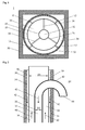
- FIG. 1 shows a schematic cross-sectional view through a fireplace system according to the invention 1.
- the chimney 1 consists of an outer chimney pipe 10, in which an inner chimney pipe 20 is approximately concentrically introduced.
- spacers 26 are fixed, which center the inner chimney pipe 20 in the outer chimney pipe 10.
- the outer chimney pipe 10 itself is in turn centered over spacers 12 in a support shaft 50 or in an existing insulated stainless steel chimney pipe 52.
- This arrangement results in areas 30, 32, 34, in which gases can be transported.
- the region 30 which is formed as an annular gap between the outer chimney pipe 10 and the inner chimney pipe 20, the hot combustion gases are transported by a boiler 110 upwards.
- the region 32 which is located within the inner chimney pipe 20, fresh air is transported down to the burner 120.
- fresh air can also be transported to the burner 120 in the region 34 which is located between the outer chimney pipe 10 and the support shaft 50 or the stainless steel chimney pipe 52.
- the transport of fresh air is in FIG. 2 arranged by the arrows 42.
- the transport of hot combustion gases is in FIG. 2 represented by the arrows 40.
- the fireplace system 1 according to the invention is thus very well suited for retrofitting existing chimney systems.
- existing state of the art fireplace system is in many cases in the in Fig. 1 shown often masonry support shaft 50 has already been withdrawn to the outside insulated stainless steel tube 52.
- the fireplace system 1 according to the invention is drawn into this already existing stainless steel tube 52, which then acts as a support tube 52.
- the outer chimney pipe 10 is then centered by means of the spacers 12 in the support tube 52.
- the chimney system 1 is designed so that the combustion gases 40 condense in the annular gap 30 between the inner chimney pipe 20 and outer chimney pipe 10, so that the condensing constituents no longer get into the environment, but can be collected and neutralized. Therefore, the fireplace system 1 according to the invention also contributes to a significant reduction of the emissions of the heating system 100.
- the inner chimney pipe 20, the outer chimney pipe 10 and the spacers 26 which space the inner chimney pipe 20 in the outer chimney pipe 10 must be able to withstand the strongly acidic condensate (sulfuric acid or sulphurous acid) permanently. They are therefore preferably made of polyvinylidene fluoride (PVDF) a highly acid-resistant and temperature-resistant plastic. Since the spacers 12 between outer chimney pipe 10 and support shaft 50 or support tube 52 are not exposed to this acid load, a less expensive plastic or stainless steel can be used for this purpose.
- PVDF polyvinylidene fluoride
- FIG. 2 shows a schematic longitudinal section through an upper chimney end 60 of a chimney 1.
- the inner chimney pipe 20 is in a cross tube 62, which is here preferably arcuate.
- the cross tube 62 penetrates the outer chimney pipe 10 and optionally the support shaft 50 or an additional support tube 52 and extends into the open.
- At the End of the cross tube 62 is in an intake manifold 64, which is directed downward towards the ground. This prevents rainwater or birds from entering the inner chimney pipe 20. At the same time it is ensured by this arrangement that no combustion gases are sucked in as fresh air.
- the diameter D1 of the outer chimney pipe 10 and the diameter D2 of the inner chimney pipe 20 are shown only schematically.
- the outer chimney pipe may have a diameter D1 of, for example 315 mm, wherein the inner chimney pipe in such a case may have a diameter of 80 - 100 mm.
- the inner chimney pipe 20 may be formed from sections of flexible pipe 22 which are separated by smooth tube sections 24.
- the flexible tube 22 has the advantage that the size of the surface is greatly increased by its wavy surface compared to a smooth tube, which promotes heat transfer and condensation.
- Conventional flexible tubes have an approximately 3 times greater surface area compared to equal-length smooth tubes.
- flexible tubes compared with plain tubes have a smaller wall thickness, which is preferably only 1/3 of the wall thickness of corresponding smooth tubes.
- small turbulences of the sweeping gases the laminar flow break up and thus additionally favor the heat transfer between hot combustion gases 40 and cold fresh air 42.
- the spacers 26 between the inner chimney pipe 20 and the outer chimney pipe 10 are fixed to sections of smooth tube 24 of the inner chimney pipe 20.
- the spacers 26 are preferably made of short pipe sections, which are welded edgewise to the sections of smooth tube 24.
- the original diameter of the spacers 26 is selected to center the inner chimney pipe 20 under tension in the outer chimney pipe 20.
- three spacers 26 are attached to a section of smooth tube 24.
- the sections of smooth tube 24 may have a length of about 10 cm, wherein the sections of flexible tube 22 may have a length of about 2 meters.
- spacers 12 are provided on the outer chimney pipe, which the outer chimney pipe in the support shaft 50 center.
- the spacers 12 are also made of suitable pipe sections or metal rings.
- condensation body 70 may be arranged in the annular gap 30 between outer chimney pipe 10 and inner chimney pipe 20, which are usually lattice-shaped or hollow packing of PDVF plastic, and serve as condensation nuclei for the combustion gases 40.
- the condensation body 70 conduct the heat of condensation of the combustion gases 40 by heat conduction both to the inner and to the outer chimney pipe 10, 20th
- the chimney pipes 10, 20 can be made in different ways. Smaller diameters usually become produced by extrusion, with larger diameter - from about 400 mm - can be wound from a profile band, which is spirally welded together, thus resulting in any size and any length of chimney pipe.
- This winding technique has the further advantage for the present application as a chimney pipe, that under certain circumstances, a non-smooth surface is formed, which improves the condensation of the combustion gases and the heat transfer to the fresh air 42 similar to a flexible tube.
- FIG. 4 schematically shows a heating system 100, which is connected to a fireplace system 1.
- a heating chamber 150 which serves as a buffer for the fresh air 42 necessary for combustion is a boiler 110, usually for heating water, which is heated with a burner 120.
- the combustion of the fuel such as gas, oil or wood pellets, produces hot combustion gases 40 which are directed within the outer chimney pipe 10 towards the environment.
- the hot combustion gases 40 condense in particular on the outer wall of the inner chimney pipe 20 and thereby warm fresh air 42, which is transported through the inner chimney pipe 20.
- the resulting condensate is collected at the bottom of the chimney pipe 10 and passed into a Neutralisationsbox 140 containing an activated carbon filter and a neutralization granules (limestone).
- Neutralisationsbox 140 the sulfuric acid-containing condensate is purified and neutralized, so that pure water is produced, which can be passed into the sewer.
- the boiler room 150 is substantially ventilated via the chimney system 1.
- the boiler room 150 may, for safety reasons, however, also have further ventilation openings which, however, allow only minute amounts of fresh air into the heating space 150.
- ventilation openings are closed with movable curtains, which indeed ensure the desired pressure equalization, but minimize the heat radiation losses of the heating chamber 150.
- the burner 120 is advantageous to operate in a continuous, modulating operating mode, so that the burner 120 is normally not switched off during the heating period, ie approximately from September to March.
- a night reduction in which the burner is usually switched off for several hours, also does not take place.
- the burner 120 is to be varied by regulating the fuel supply only in its performance, so be modulated and not permanently on or off, as is the case with conventional heating systems.
- the burner uses about 20% - 30% smaller nozzles compared to nozzles that would be used in conventional design of the heating system to produce much lower power during operation.
- an oil boiler with a rated output of 1250 kW is reduced by smaller nozzles to a rated output of 800 kW.
- the oil boiler can be operated modulating in a power range of, for example, 200-800 kW, whereby shutdowns of the burner during the heating period usually do not occur.
- the burner is thus driven essentially in continuous operation.
- a large flue system 2 is shown schematically in cross section. It comprises a support tube 52 or alternatively a support shaft, which may be an already existing large-scale chimney of conventional design.
- Large fireplaces are used, for example, in industry, in power plants or waste incineration plants and can reach chimney heights of 100m and more.
- the chimney draft is usually lined with an insulated stainless steel chimney pipe. Also, such a large fireplace can be converted to a fireplace system according to the invention and used for heat recovery.
- a plurality of inventive fireplace systems 1 are fed into the possibly existing stainless steel chimney pipe 52, which is used as a support tube 52, each comprising an outer chimney pipe 10 and an inner chimney pipe 20.
- the support tube 52 may, for example, have a diameter of 3 m, wherein the seven outer chimney tubes 10 may each have, for example, a diameter of 315 mm or more.
- the drawn-in chimney systems 1 are combined as packages and fastened correspondingly within the support tube 52.
- the combustion gases 40 are guided in the respective annular gaps 30 between the outer 10 and inner chimney pipe 20, wherein within the inner chimney pipes 20 and outside the outer chimney pipes 10 to be heated fresh air 42 is transported, which is supplied to the heating or incinerator.
- the reduction of the total cross section for the transport of the combustion gases 40 is in turn possible by a greatly reduced exhaust gas temperature and by a mass flow reduction by condensation, advantageously both when entering the large chimney 2 and by the further cooling of the combustion gases 42 in the large chimney. 2
- Fig. 5 For example, seven chimney systems 1 are shown, which are arranged as a chimney pipe package within a single support tube 52.
- the number, arrangement and size of the multiple chimney systems 1 in a large chimney 2 can be varied depending on the application and volume of the combustion gases 40.
Applications Claiming Priority (1)
| Application Number | Priority Date | Filing Date | Title |
|---|---|---|---|
| DE200810005542 DE102008005542A1 (de) | 2008-01-22 | 2008-01-22 | Kaminsystem |
Publications (2)
| Publication Number | Publication Date |
|---|---|
| EP2083218A2 true EP2083218A2 (fr) | 2009-07-29 |
| EP2083218A3 EP2083218A3 (fr) | 2014-11-26 |
Family
ID=40568746
Family Applications (1)
| Application Number | Title | Priority Date | Filing Date |
|---|---|---|---|
| EP09000875.6A Withdrawn EP2083218A3 (fr) | 2008-01-22 | 2009-01-22 | Système de cheminée |
Country Status (2)
| Country | Link |
|---|---|
| EP (1) | EP2083218A3 (fr) |
| DE (1) | DE102008005542A1 (fr) |
Cited By (3)
| Publication number | Priority date | Publication date | Assignee | Title |
|---|---|---|---|---|
| EP2385302A1 (fr) * | 2010-05-06 | 2011-11-09 | Technaflon AG | Système de cheminée |
| EP2469166A1 (fr) * | 2010-12-23 | 2012-06-27 | Opsinox | Système combiné d'évacuation de gaz combustible, d'alimentation en air et d'évacuation de l'air de ventilation |
| BE1027093B1 (nl) * | 2019-03-07 | 2020-10-05 | Debatra Bvba | Een gecombineerd luchttoevoer en verbrandingsgasafvoer systeem voor meerdere gashaarden |
Citations (1)
| Publication number | Priority date | Publication date | Assignee | Title |
|---|---|---|---|---|
| DE3421112A1 (de) | 1984-06-06 | 1984-10-11 | Paul Reinhard Dipl.-Ing. 8000 München Kramer | Vorrichtung zum abfuehren von abgasen hoher temperatur, insb. von rauchgasen aus gebaeuden mit der bestandteile der abgase durch weitestgehende abkuehlung auf raumtemperatur zur kondensation gebracht werden, das kondensat abgefuehrt u. d. kondensationswaerme rueckgewonnen wird |
Family Cites Families (8)
| Publication number | Priority date | Publication date | Assignee | Title |
|---|---|---|---|---|
| NL8502173A (nl) * | 1985-08-01 | 1987-03-02 | Bronswerk Bv | Luchttoevoer- en verbrandingsgasafvoer-kanalensysteem voor meerdere gesloten stooktoestellen. |
| CH687833A5 (de) * | 1993-07-29 | 1997-02-28 | Horst Wunsch | Fuellkoerperanordnung. |
| DE4331194C1 (de) * | 1993-09-14 | 1994-10-06 | Braas Gmbh | Doppelwandiges Rohrleitungssystem |
| DE29516284U1 (de) * | 1995-10-13 | 1995-12-21 | Krauss Kaminwerke Muenchen Gei | Zweischaliger Schornstein |
| DE19802417C1 (de) * | 1998-01-23 | 1999-05-12 | Centrotherm Abgastechnik Gmbh | Bausatz für eine Luft-Abgas-Leitung |
| DE20007420U1 (de) * | 2000-04-19 | 2000-06-29 | Franke Thomas | Wärmetauscher |
| DE20300465U1 (de) * | 2003-01-10 | 2003-07-24 | Erlus Baustoffwerke | Be- und Entlüftungsanlage mit Gegenstrombetrieb |
| US7069925B2 (en) * | 2003-03-06 | 2006-07-04 | Hni Tech Inc | Pressure relief system for a gas fireplace |
-
2008
- 2008-01-22 DE DE200810005542 patent/DE102008005542A1/de not_active Ceased
-
2009
- 2009-01-22 EP EP09000875.6A patent/EP2083218A3/fr not_active Withdrawn
Patent Citations (1)
| Publication number | Priority date | Publication date | Assignee | Title |
|---|---|---|---|---|
| DE3421112A1 (de) | 1984-06-06 | 1984-10-11 | Paul Reinhard Dipl.-Ing. 8000 München Kramer | Vorrichtung zum abfuehren von abgasen hoher temperatur, insb. von rauchgasen aus gebaeuden mit der bestandteile der abgase durch weitestgehende abkuehlung auf raumtemperatur zur kondensation gebracht werden, das kondensat abgefuehrt u. d. kondensationswaerme rueckgewonnen wird |
Cited By (5)
| Publication number | Priority date | Publication date | Assignee | Title |
|---|---|---|---|---|
| EP2385302A1 (fr) * | 2010-05-06 | 2011-11-09 | Technaflon AG | Système de cheminée |
| WO2011138436A1 (fr) * | 2010-05-06 | 2011-11-10 | Technaflon Ag | Système de cheminée |
| EP2469166A1 (fr) * | 2010-12-23 | 2012-06-27 | Opsinox | Système combiné d'évacuation de gaz combustible, d'alimentation en air et d'évacuation de l'air de ventilation |
| BE1019666A5 (nl) * | 2010-12-23 | 2012-09-04 | Opsinox | Gecombineerd rookgasafvoer, luchttoevoer en ventilatieluchtafvoersysteem. |
| BE1027093B1 (nl) * | 2019-03-07 | 2020-10-05 | Debatra Bvba | Een gecombineerd luchttoevoer en verbrandingsgasafvoer systeem voor meerdere gashaarden |
Also Published As
| Publication number | Publication date |
|---|---|
| DE102008005542A1 (de) | 2009-07-23 |
| EP2083218A3 (fr) | 2014-11-26 |
Similar Documents
| Publication | Publication Date | Title |
|---|---|---|
| DE3614385C2 (fr) | ||
| WO2009100881A2 (fr) | Centrale au charbon et procédé d'exploitation de la centrale au charbon | |
| DE112008001319T5 (de) | Staubkohlenkessel, Staubkohle-Verbrennungsverfahren, Staubkohlenbrennstoff-Wärmeleistungserzeugungssystem und Abgasreinigungssystem für Staubkohlenkessel | |
| EP0133894A1 (fr) | Procédé et dispositif de réchauffage des fumées après leur désulfuration en milieu humide | |
| WO2007093453A2 (fr) | Générateur de vapeur | |
| EP2385302B1 (fr) | Système de cheminée | |
| EP2787279A1 (fr) | Procédé de fonctionnement d'une chaudière à combustible solide ayant une récirculation des fumées | |
| DE202013001669U1 (de) | Anlage mit Biomassen-Mischverbrennung | |
| DE3317424C2 (fr) | ||
| DE102011084902B3 (de) | Verfahren und vorrichtung zur fluiderwärmung durch verbrennung kohlenstoffbasierter brennstoffe | |
| EP2083218A2 (fr) | Système de cheminée | |
| EP0689656B1 (fr) | Cheminee de condensation | |
| DE19518076C2 (de) | Schornsteinsystem für einen Brennwertkessel | |
| CH676435A5 (fr) | ||
| EP2169310A1 (fr) | Système de cheminée | |
| DE3228885A1 (de) | Anlage zur rueckgewinnung von energie aus abgasen von aus feuerungseinrichtungen austretenden rauchgasen und zur abgasreinigung | |
| DE202006003153U1 (de) | Energierückgewinnungsmodul | |
| DE3329777A1 (de) | Heizungskessel fuer fluessige und gasfoermige brennstoffe | |
| EP2351966B1 (fr) | Système d'échangeur de chaleur | |
| DE102010012006A1 (de) | Wärmetauscher für eine thermische Abluftreinigungsanlage und Verfahren zum Reinigen eines Abluftstroms | |
| DE202008006043U1 (de) | Kaminaufsatz für Kaminzugreduktion | |
| DE102007023051A1 (de) | Kessel mit Brennmaterial aufnehmenden Brennraum | |
| DE1291046B (de) | Verbrennungsofen fuer minderwertige Brennstoffe, z. B. Muell, mit Waermetauscher zur Rauchgasabkuehlung | |
| DE102010046858B4 (de) | Heizkessel und Wärmeversorgungsanlage für Festbrennstoffe sowie ein Verfahren zur Verbrennung von Festbrennstoffen | |
| DE3218593A1 (de) | Verfahren zur rueckgewinnung der kaminabgaswaerme von mit grossfeuerungen, hausfeuerungen oder einzelfeuerungen ausgestatteten gebaeuden zur erwaermung der raumluft und warmluftkamin zur durchfuehrung des verfahrens |
Legal Events
| Date | Code | Title | Description |
|---|---|---|---|
| PUAI | Public reference made under article 153(3) epc to a published international application that has entered the european phase |
Free format text: ORIGINAL CODE: 0009012 |
|
| AK | Designated contracting states |
Kind code of ref document: A2 Designated state(s): AT BE BG CH CY CZ DE DK EE ES FI FR GB GR HR HU IE IS IT LI LT LU LV MC MK MT NL NO PL PT RO SE SI SK TR |
|
| AX | Request for extension of the european patent |
Extension state: AL BA RS |
|
| PUAL | Search report despatched |
Free format text: ORIGINAL CODE: 0009013 |
|
| AK | Designated contracting states |
Kind code of ref document: A3 Designated state(s): AT BE BG CH CY CZ DE DK EE ES FI FR GB GR HR HU IE IS IT LI LT LU LV MC MK MT NL NO PL PT RO SE SI SK TR |
|
| AX | Request for extension of the european patent |
Extension state: AL BA RS |
|
| RIC1 | Information provided on ipc code assigned before grant |
Ipc: F23J 13/02 20060101AFI20141022BHEP |
|
| AKY | No designation fees paid | ||
| AXX | Extension fees paid |
Extension state: RS Extension state: AL Extension state: BA |
|
| REG | Reference to a national code |
Ref country code: DE Ref legal event code: R108 |
|
| STAA | Information on the status of an ep patent application or granted ep patent |
Free format text: STATUS: THE APPLICATION IS DEEMED TO BE WITHDRAWN |
|
| 18D | Application deemed to be withdrawn |
Effective date: 20150527 |