EP2083205A2 - Connector for connecting conduits for liquid or gaseous media - Google Patents
Connector for connecting conduits for liquid or gaseous media Download PDFInfo
- Publication number
- EP2083205A2 EP2083205A2 EP08021570A EP08021570A EP2083205A2 EP 2083205 A2 EP2083205 A2 EP 2083205A2 EP 08021570 A EP08021570 A EP 08021570A EP 08021570 A EP08021570 A EP 08021570A EP 2083205 A2 EP2083205 A2 EP 2083205A2
- Authority
- EP
- European Patent Office
- Prior art keywords
- plug
- web
- seal
- connector
- plug part
- Prior art date
- Legal status (The legal status is an assumption and is not a legal conclusion. Google has not performed a legal analysis and makes no representation as to the accuracy of the status listed.)
- Granted
Links
Images


Classifications
-
- F—MECHANICAL ENGINEERING; LIGHTING; HEATING; WEAPONS; BLASTING
- F02—COMBUSTION ENGINES; HOT-GAS OR COMBUSTION-PRODUCT ENGINE PLANTS
- F02M—SUPPLYING COMBUSTION ENGINES IN GENERAL WITH COMBUSTIBLE MIXTURES OR CONSTITUENTS THEREOF
- F02M35/00—Combustion-air cleaners, air intakes, intake silencers, or induction systems specially adapted for, or arranged on, internal-combustion engines
- F02M35/10—Air intakes; Induction systems
- F02M35/10091—Air intakes; Induction systems characterised by details of intake ducts: shapes; connections; arrangements
- F02M35/10144—Connections of intake ducts to each other or to another device
-
- F—MECHANICAL ENGINEERING; LIGHTING; HEATING; WEAPONS; BLASTING
- F16—ENGINEERING ELEMENTS AND UNITS; GENERAL MEASURES FOR PRODUCING AND MAINTAINING EFFECTIVE FUNCTIONING OF MACHINES OR INSTALLATIONS; THERMAL INSULATION IN GENERAL
- F16L—PIPES; JOINTS OR FITTINGS FOR PIPES; SUPPORTS FOR PIPES, CABLES OR PROTECTIVE TUBING; MEANS FOR THERMAL INSULATION IN GENERAL
- F16L37/00—Couplings of the quick-acting type
- F16L37/08—Couplings of the quick-acting type in which the connection between abutting or axially overlapping ends is maintained by locking members
- F16L37/084—Couplings of the quick-acting type in which the connection between abutting or axially overlapping ends is maintained by locking members combined with automatic locking
- F16L37/088—Couplings of the quick-acting type in which the connection between abutting or axially overlapping ends is maintained by locking members combined with automatic locking by means of a split elastic ring
- F16L37/0885—Couplings of the quick-acting type in which the connection between abutting or axially overlapping ends is maintained by locking members combined with automatic locking by means of a split elastic ring with access to the split elastic ring from a radial or tangential opening in the coupling
Definitions
- the invention relates to a connector for connecting lines for liquid or gaseous media, comprising a first connector part, which has a through-channel, a second connector part, in which the first connector part can be inserted in a plug-in direction and which has a through-channel, and an am second plug member held seal, wherein the second connector part has a at least over one or more portions of this connector part extending in the circumferential direction, projecting in the direction of the central longitudinal axis of the second connector part web, which is arranged relative to the insertion of the first connector part in front of the seal.
- Such connectors which are also referred to as “hose quick couplings", are used in particular in the automotive sector for connecting charge air lines and cooling water lines.
- Such a connector is for example from the WO 2007/045281 A1 known.
- the seal is arranged on the second plug part, which is also referred to as a plug and in which the first plug part, which is also referred to as a socket, can be inserted.
- the two connector parts are latched together via a detent spring and a sealing lip of the seal is located on a sealing surface of the first connector part circumferentially, to effect the mutual sealing of the two connector parts.
- a problem with this conventional connector is that dirt can get into the sealing area from the outside, which can lead to damage and leaks.
- the seal is held in a sealing groove of the second connector part, which is bounded on the side of the insertion opening by an inwardly projecting web. This has a slope inclined to the longitudinal axis and thus acts as a funnel, which leads incoming dirt to the sealing lip.
- In the area between the sealing lip and the sealing surface of the first connector part penetrated dirt can be due to vibration and occurring minor relative movements between the two plug parts are transported over time to the sealing edge.
- the dirt particles that reach the sealing edge can cause leaks and dirt particles that slip over the sealing lip can damage them, resulting in permanent leaks.
- the object of the invention is to provide an improved connector of the type mentioned. According to the invention, this is achieved by a plug connection with the features of patent claim 1.
- the web forms at least over one or more portions of its course in the circumferential direction of the second connector part in the longitudinal center section through the second connector part on the side facing away from the seal or on the insertion of the second connector part, in which the first Plug part for closing the connector can be inserted, facing side of a depression.
- This depression is preferably formed by a curved course of the web forming the wall of the second plug part, wherein it would also be conceivable and possible to form the recess by a recess in the material of the web.
- the formed recessed area is limited in the radial direction to the central longitudinal axis of the second connector part through the web.
- the bottom of the web in the region of the recess at least one opening.
- several such Circumferential direction of the second connector part spaced openings present. Through these openings can be removed into the depression reaching dirt.
- the openings open on the other side of the web preferably in a space open to the outside space of the second connector part. It would also be conceivable and possible, for example, for these openings to open directly into the exterior space. An opening in a closed receiving space of the second connector part would be conceivable and possible.
- the web extends annularly, in particular annular, around the central longitudinal axis of the second plug part and the recess extends in the circumferential direction of the web over its entire course, that is, overall annular, in particular annular, formed.
- the seal held on the second plug part has, in addition to the sealing lip, a dirt lip.
- a dirt lip This is, as well as the sealing lip, on the first plug part, preferably over the entire circumference of the first plug part, and that outside of the sealed by the sealing lip interior of the connector. Ie. the contact area of the sealing lip is closer to the plug-in end of the first plug part than the contact area of the dirt lip. Dirt particles that reach over the bridge to the seal are thus - at least for the most part, prevented from advancing to the sealing lip, whereby the permanent tightness of the connector can be further improved.
- the first connector part and the second connector part are preferably locked together, in particular by means of at least one detent spring, wherein the latch for opening the connector is conveniently unlatched.
- Such locking devices are known.
- FIG. 1 to 18 An embodiment of a connector according to the invention in the form of a quick coupling for connecting lines for liquid or gaseous media is in the Fig. 1 to 18 shown.
- the two connector parts 1, 2 each have a through channel 3, 4 for the passage of the medium.
- the first connector part 1 is inserted into a lying parallel to the central longitudinal axis 12 of the first connector part 1 insertion 5 in the passageway 4 of the second connector part 2.
- the front insertion side end 6 of the first connector part 1 is inserted into the insertion opening 7 of the second connector part 2 formed by the insertion-side mouth of the through-channel 4.
- the first connector part 1 is locked in the second connector part 2.
- the inclined surface and the latching shoulder 10 are formed by a first plug part 1 surrounding the outside annular projection.
- a seal 11 is used to seal an interior of the connector, which comprises the passage 3 of the first connector part 1 and that portion of the passage channel 4 of the second connector part 2, which extends from the insertion opening 7 opposite end of the second connector part 2 to the seal 11.
- the seal 11 is annular, in particular annular, formed. The seal 11 is held on the second connector part 2, wherein it rests against the inner, the central longitudinal axis 13 facing surface of the second connector part 2 and the central longitudinal axis 13 surrounds.
- the central longitudinal axis 12 of the first connector part 1 coincides with the central longitudinal axis 13 of the second connector part 2.
- the seal 11 and the mutual sealing between the two plug parts 1, 2 serving surfaces of the two connector parts 1, 2 are rotationally symmetrical.
- the two connector parts 1, 2 are formed substantially rotationally symmetrical overall (apart from locking elements, anti-rotation elements and the like.).
- the seal 11 has a sealing lip 14, which serves to seal against the first connector part 1 and at an outer, i. facing away from the central longitudinal axis 12, surface 15 of the first connector part 1 abuts circumferentially. This outer surface 15 forms a sealing surface of the first plug part 1.
- the seal 11 further comprises a dirt lip formed by a further lip 16.
- the dirty lip 16 is also on the outer surface 15 of the first connector part 1 circumferentially.
- the sealing lip 14 and the dirt lip 16 are connected to each other in the area of their lip bases.
- the lip base of a lip of a seal is understood to be that region of the seal from which the lip is freely projecting from another part of the seal.
- both lips 14, 16 relative to the central longitudinal axis 12, 13 of the first and second connector part 1, 2 is still slightly inclined (less inclined than in the open state of the connector) whereby tolerances can be accommodated.
- the sealing lip 14 and dirt lip 16 are connected, starting from their connecting region at their lip bases, via a connecting web 20 to a sealing foot 19. There could also be more than one such connecting web 20, the lip bases in the area between the connecting webs 20 being connected to one another via connecting sections.
- the sealing foot 19 is held in a sealing groove 21, which is open towards the central longitudinal axis 13, of the second plug part 2. It is also conceivable and possible that, for example, the sealing foot 19 is clamped in a sealing groove 21 which opens in the axial direction.
- the outer diameter of the seal 11 in the relaxed state slightly larger than the diameter of the bottom of the seal groove 21st
- the sealing foot 19 comprises in the embodiment shown a protruding from the connecting web 20 in the direction of the insertion opening 7 of the second connector part 2 portion 19 a, which could also be referred to as the base portion or base body of the seal 11, and protruding in the opposite direction portion 19 b, which also as static sealing lip could be called.
- At this section 19b is on the second plug part 2 side facing a survey available, which forms a sealing edge for sealing the seal 11 relative to the second plug part 2.
- the web 27 forms on its side facing away from the seal 11 side, so the insertion opening 7 side facing a recess 28.
- an undercut contour is formed by the web 27 in the radial direction.
- the region of the undercut forms the depression 28.
- the recess 28 extends in the circumferential direction of the web 27 groove-shaped.
- a plurality of circumferentially spaced openings 29 are formed at the bottom of the recess. These open on the other side of the web 27 in the open space to the outside space 36 of the second connector part. 2
- the web 27 is formed by a portion of the wall of the second plug part, which connects via a bend to a cylindrical shell portion 32 of the wall of the plug part 2 (see. 8 and 9 ).
- the remote from the shell portion 32 inner end of the web 27 is connected via a substantially extending over 180 ° bend (seen in longitudinal section through the second connector part 2) with a limiting web 26, the circumferential seal groove 21 for receiving the seal 11 on the insertion opening 7 directed side of the seal groove 21 limited.
- the sealing groove 21 is bounded by a further boundary web 33, which is connected via a bend with a cylindrical shell portion 34 of the second plug part 2.
- the boundary webs 26, 33 are connected via turns with the bottom web 35 of the seal groove 21.
- the boundary web 26, with which the web 27 is connected via a bend, has a smaller radial extent than the web 27.
- the sealing web 21 delimiting boundary web 26 also has an undercut shape. In the space formed by the undercut 30 can reach over the web 27 reaching and held by the dirt lip 16 dirt particles. The space 30 thus forms a receiving space for such dirt particles.
- the sealing foot 19 has at its insertion opening 7 facing end face (ie at the free end of the portion 19 a) a plurality of circumferentially spaced grooves 31 (see. Fig. 2 and 3 ).
- FIGS. 14 and 15 When the outer surface 15 of the first connector part 1 starts against the sealing lip 14, this is increasingly pressed or pivoted (with reduction of the inclination of the sealing lip 14 relative to the central longitudinal axis 13), wherein the dirt lip 16 is placed, ie their inclination relative to the central longitudinal axis 13 of the second connector part increases.
- the diameter of the released by the sealing lip 14 opening is increased and the diameter of the released by the dirt lip 16 opening is reduced.
- the inlet slope of the first connector part 1 can be formed by an inlet chamfer or an inlet radius.
- the sealing lip 14 and the dirt lip 16 are made of a rubber-elastic material, such as an elastomer, a termoplastischen elastomer or silicone.
- a rubber-elastic material such as an elastomer, a termoplastischen elastomer or silicone.
- the seal 11 as a whole consists of such a rubber-elastic material. It is also conceivable and possible that this additionally has other materials, for example as reinforcing inserts.
- the plug parts 1, 2 may be formed of plastic and / or metal.
- FIG Fig. 19 A somewhat modified embodiment of the seal 11 is shown in FIG Fig. 19 shown.
- the design of the seal 11 could also be interpreted in this embodiment such that the sealing lip 14 and the dirt lip 16 are connected to each other in the region of their lip bases.
- the interconnected lip bases of the sealing lip 14 and the dirt lip 16 are thus in turn connected in this view via a connecting web with the sealing foot 19, in this embodiment, with the edge region of the sealing foot 19th
- the seal 11 could also have more than one sealing lip and / or dirt lip.
- the dirt lip 16 could also be omitted. It could also be provided several seals for sealing between the first and second connector part.
- the web 27 it would also be conceivable and possible for the web 27 to extend over only a part, preferably the majority, of the complete circumference of the second plug part 2, with one or more part-ring-shaped sections of the web 27 being present.
- the depression 28 it would also be conceivable and possible for the depression 28 to extend only over a part, preferably the majority, of the course of the web 27 in its circumferential direction.
- lines for liquid or gaseous media are simple, reliable and permanently sealed together connectable.
- lines e.g. in the form of hoses, pipes or in the form of channels formed in media-carrying parts.
- connections can be made for lines in which there is a relatively low pressure, for example up to 6 bar.
- Such lines are used, for example, in cooling water lines, in particular for internal combustion engines, or charge air lines for internal combustion engines.
Landscapes
- Engineering & Computer Science (AREA)
- General Engineering & Computer Science (AREA)
- Mechanical Engineering (AREA)
- Chemical & Material Sciences (AREA)
- Combustion & Propulsion (AREA)
- Quick-Acting Or Multi-Walled Pipe Joints (AREA)
- Joints With Pressure Members (AREA)
Abstract
Description
Die Erfindung bezieht sich auf eine Steckverbindung zum Verbinden von Leitungen für flüssige oder gasförmige Medien, umfassend ein erstes Steckerteil, welches einen Durchgangskanal aufweist, ein zweites Steckerteil, in welches das erste Steckerteil in eine Einsteckrichtung einsteckbar ist und welches einen Durchgangskanal aufweist, und eine am zweiten Steckerteil gehaltene Dichtung, wobei das zweite Steckerteil einen zumindest über einen oder mehrere Abschnitte dieses Steckerteils in dessen Umfangsrichtung verlaufenden, in Richtung zur zentralen Längsachse des zweiten Steckerteils abstehenden Steg aufweist, der bezogen auf die Einsteckrichtung des ersten Steckerteils vor der Dichtung angeordnet ist.The invention relates to a connector for connecting lines for liquid or gaseous media, comprising a first connector part, which has a through-channel, a second connector part, in which the first connector part can be inserted in a plug-in direction and which has a through-channel, and an am second plug member held seal, wherein the second connector part has a at least over one or more portions of this connector part extending in the circumferential direction, projecting in the direction of the central longitudinal axis of the second connector part web, which is arranged relative to the insertion of the first connector part in front of the seal.
Derartige Steckverbindungen, die auch als "Schlauchschnellkupplungen" bezeichnet werden, werden insbesondere im Automobilbereich zur Verbindung von Ladeluftleitungen und Kühlwasserleitungen eingesetzt.Such connectors, which are also referred to as "hose quick couplings", are used in particular in the automotive sector for connecting charge air lines and cooling water lines.
Eine derartige Steckverbindung ist beispielsweise aus der
Ein Problem bei dieser herkömmlichen Steckverbindung besteht darin, dass Schmutz von außen in den Dichtbereich gelangen kann, der zu Beschädigungen und Leckagen führen kann. Die Dichtung ist in einer Dichtungsnut des zweiten Steckerteils gehalten, die auf der Seite der Einstecköffnung von einem nach innen vorspringenden Steg begrenzt wird. Dieser weist einen zur Längsachse geneigten Verlauf auf und wirkt somit als Trichter, welcher eintretenden Schmutz zur Dichtlippe führt. In den Bereich zwischen der Dichtlippe und der Dichtfläche des ersten Steckerteils eingedrungener Schmutz kann durch Vibrationen und auftretende kleinere Relativbewegungen zwischen den beiden Steckerteilen im Laufe der Zeit immer weiter zur Dichtkante transportiert werden. Durch die Schmutzpartikel, welche die Dichtkante erreichen kann es zu Undichtheiten kommen und durch über die Dichtlippe rutschende Schmutzpartikel kann diese beschädigt werden, mit der Folge von dauerhaften Leckstellen.A problem with this conventional connector is that dirt can get into the sealing area from the outside, which can lead to damage and leaks. The seal is held in a sealing groove of the second connector part, which is bounded on the side of the insertion opening by an inwardly projecting web. This has a slope inclined to the longitudinal axis and thus acts as a funnel, which leads incoming dirt to the sealing lip. In the area between the sealing lip and the sealing surface of the first connector part penetrated dirt can be due to vibration and occurring minor relative movements between the two plug parts are transported over time to the sealing edge. The dirt particles that reach the sealing edge can cause leaks and dirt particles that slip over the sealing lip can damage them, resulting in permanent leaks.
Eine weitere Dichtung der eingangs genannten Art geht aus der
Weitere Steckverbindungen, bei denen die Dichtung in einer in achsialer Richtung offenen Nut gehalten ist, gehen aus der
Aufgabe der Erfindung ist es eine verbesserte Steckverbindung der eingangs genannten Art bereitzustellen. Erfindungsgemäß gelingt dies durch eine Steckverbindung mit den Merkmalen des Patentanspruchs 1.The object of the invention is to provide an improved connector of the type mentioned. According to the invention, this is achieved by a plug connection with the features of
Bei der Steckverbindung gemäß der Erfindung bildet der Steg zumindest über einen oder mehrere Abschnitte seines Verlaufs in Umfangsrichtung des zweiten Steckerteils im Längsmittelschnitt durch das zweite Steckerteil gesehen auf der von der Dichtung abgewandten Seite bzw. auf der der Einstecköffnung des zweiten Steckerteils, in welche das erste Steckerteil zum Schließen der Steckverbindung einsteckbar ist, zugewandten Seite eine Vertiefung aus. Diese Vertiefung wird vorzugsweise durch einen gebogenen Verlauf der den Steg bildenden Wandung des zweiten Steckerteils gebildet, wobei es auch denkbar und möglich wäre, die Vertiefung durch eine Ausnehmung im Material des Steges auszubilden. Der ausgebildete vertiefte Bereich ist in radialer Richtung zur zentralen Längsachse des zweiten Steckerteils hin durch den Steg begrenzt.In the connector according to the invention, the web forms at least over one or more portions of its course in the circumferential direction of the second connector part in the longitudinal center section through the second connector part on the side facing away from the seal or on the insertion of the second connector part, in which the first Plug part for closing the connector can be inserted, facing side of a depression. This depression is preferably formed by a curved course of the web forming the wall of the second plug part, wherein it would also be conceivable and possible to form the recess by a recess in the material of the web. The formed recessed area is limited in the radial direction to the central longitudinal axis of the second connector part through the web.
Von dieser Vertiefung kann in den Bereich zwischen die beiden Steckerteile eindringender Schmutz aufgenommen werden, sodass einem Vordringen von Schmutz zur Dichtung entgegengewirkt wird.From this depression can be added to the area between the two connector parts penetrating dirt, so that a penetration of dirt is counteracted to the seal.
In einer vorteilhaften Ausführungsform der Erfindung weist der Boden des Stegs im Bereich der Vertiefung mindestens eine Öffnung auf. Vorzugsweise sind mehrere solche in Umfangsrichtung des zweiten Steckerteils voneinander beabstandete Öffnungen vorhanden. Durch diese Öffnungen kann in die Vertiefung gelangender Schmutz abgeführt werden. Die Öffnungen münden hierbei auf der anderen Seite des Stegs vorzugsweise in einen zum Außenraum hin offenen Raum des zweiten Steckerteils. Denkbar und möglich wäre es beispielsweise auch, dass diese Öffnungen direkt in den Außenraum münden. Auch eine Mündung in einen geschlossenen Aufnahmeraum des zweiten Steckerteils wäre denkbar und möglich.In an advantageous embodiment of the invention, the bottom of the web in the region of the recess at least one opening. Preferably, several such Circumferential direction of the second connector part spaced openings present. Through these openings can be removed into the depression reaching dirt. The openings open on the other side of the web preferably in a space open to the outside space of the second connector part. It would also be conceivable and possible, for example, for these openings to open directly into the exterior space. An opening in a closed receiving space of the second connector part would be conceivable and possible.
Vorzugsweise verläuft der Steg ringförmig, insbesondere kreisringförmig, um die zentrale Längsachse des zweiten Steckerteils und die Vertiefung erstreckt sich in Umfangsrichtung des Steges über dessen gesamten Verlauf, ist also insgesamt ringförmig, insbesondere kreisringförmig, ausgebildet.Preferably, the web extends annularly, in particular annular, around the central longitudinal axis of the second plug part and the recess extends in the circumferential direction of the web over its entire course, that is, overall annular, in particular annular, formed.
In einer vorteilhaften Ausführungsform der Erfindung weist die am zweiten Steckerteil gehaltene Dichtung zusätzlich zur Dichtlippe eine Schmutzlippe auf. Diese liegt, ebenso wie die Dichtlippe, am ersten Steckerteil an, vorzugsweise über den gesamten Umfang des ersten Steckerteils, und zwar außerhalb des von der Dichtlippe abgedichteten Innenraums der Steckverbindung. D. h. der Anlagebereich der Dichtlippe ist näher beim einsteckseitigen Ende des ersten Steckerteils als der Anlagebereich der Schmutzlippe. Schmutzpartikel, die über den Steg bis zur Dichtung gelangen, werden somit - zumindest großteils, von einem Vordringen bis zur Dichtlippe abgehalten, wodurch die dauerhafte Dichtheit der Steckverbindung weiter verbessert werden kann.In an advantageous embodiment of the invention, the seal held on the second plug part has, in addition to the sealing lip, a dirt lip. This is, as well as the sealing lip, on the first plug part, preferably over the entire circumference of the first plug part, and that outside of the sealed by the sealing lip interior of the connector. Ie. the contact area of the sealing lip is closer to the plug-in end of the first plug part than the contact area of the dirt lip. Dirt particles that reach over the bridge to the seal are thus - at least for the most part, prevented from advancing to the sealing lip, whereby the permanent tightness of the connector can be further improved.
Im geschlossenen Zustand der Steckverbindung sind das erste Steckerteil und das zweite Steckerteil vorzugsweise miteinander verrastet, insbesondere mittels mindestens einer Rastfeder, wobei die Verrastung zum Öffnen der Steckverbindung günstigerweise entrastbar ist. Derartige Rasteinrichtungen sind bekannt.In the closed state of the connector, the first connector part and the second connector part are preferably locked together, in particular by means of at least one detent spring, wherein the latch for opening the connector is conveniently unlatched. Such locking devices are known.
Wenn im Rahmen dieser Schrift von "innen" und "außen" die Rede ist, so ist dies auf die Lage zur zentralen Längsachse bezogen, d.h. ein weiter innen liegendes Teil hat einen geringeren Abstand von der zentralen Längsachse als ein weiter außen liegendes Teil.If in the context of this document "inside" and "outside" is mentioned, this is related to the position to the central longitudinal axis, i. a further inner part has a smaller distance from the central longitudinal axis than a part lying further outward.
Weitere Vorteile und Einzelheiten der Erfindung werden im Folgenden anhand der beiliegenden Zeichnung erläutert. In dieser zeigen:
-
Fig. 1 eine Schrägsicht des ersten und zweiten Steckerteils im geöffneten Zustand der Steckverbindung; -
Fig. 2 eine Schrägsicht entsprechendFig. 1 , das erste Steckerteil und das zweite Steckerteil abgesehen von der Dichtung aber in Längsrichtung mittig aufgeschnitten; -
Fig. 3 ein vergrößertes Detail A vonFig. 2 ; -
Fig. 4 eine Schrägsicht des zweiten Steckerteils aus einem geänderten Blickwinkel; -
Fig. 5 eine Schrägsicht des entlang der Linie BB inFig. 4 aufgeschnittenen zweiten Steckerteils; -
Fig. 6 ein vergrößertes Detail C vonFig. 5 ; -
Fig. 7 eine stirnseitige Ansicht des ersten und zweiten Steckerteils, die Steckerteile achsial ausgerichtet aber voneinander getrennt; -
Fig. 8 einen Schnitt entlang der Linie DD vonFig. 7 ; -
Fig. 9 ein vergrößertes Detail E vonFig. 8 ; -
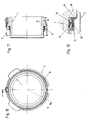
Fig. 10 eine stirnseitige Ansicht der Steckverbindung im geschlossenen Zustand der Steckverbindung; -
Fig. 11 einen Schnitt FF vonFig. 10 ; -
Fig. 12 ein vergrößertes Detail G vonFig. 11 ; -
Fig. 13, Fig. 14 (Schnitt HH vonFig. 13) und Fig. 15 (Detail I vonFig. 14 ) sowieFig. 16, Fig. 17 (Schnitt JJ vonFig. 16) und Fig. 18 (Detail K vonFig. 17 ) Darstellungen entsprechend denFig. 10 bis 12 in verschiedenen Phasen des Schließens der Steckverbindung; -
Fig. 19 einen Querschnitt durch eine Dichtung entsprechend einer etwas modifizierten Ausführungsform.
-
Fig. 1 an oblique view of the first and second connector part in the open state of the connector; -
Fig. 2 an oblique view accordinglyFig. 1 but the first plug part and the second plug part, apart from the seal, are cut centrally in the longitudinal direction; -
Fig. 3 an enlarged detail A ofFig. 2 ; -
Fig. 4 an oblique view of the second connector part from a different angle; -
Fig. 5 an oblique view of the along the line BB inFig. 4 cut second plug part; -
Fig. 6 an enlarged detail C ofFig. 5 ; -
Fig. 7 an end view of the first and second connector part, the connector parts axially aligned but separated from each other; -
Fig. 8 a section along the line DD ofFig. 7 ; -
Fig. 9 an enlarged detail E ofFig. 8 ; -
Fig. 10 an end view of the connector in the closed state of the connector; -
Fig. 11 a cut FF ofFig. 10 ; -
Fig. 12 an enlarged detail G ofFig. 11 ; -
Fig. 13, Fig. 14 (Section HH ofFig. 13) and Fig. 15 (Detail I ofFig. 14 ) such asFig. 16, Fig. 17 (Cut JJ fromFIG. 16) and FIG. 18 (Detail K ofFig. 17 ) Representations according to10 to 12 in different phases of closing the connector; -
Fig. 19 a cross section through a seal according to a somewhat modified embodiment.
Ein Ausführungsbeispiel für eine erfindungsgemäße Steckverbindung in Form einer Schnellkupplung zum Verbinden von Leitungen für flüssige oder gasförmige Medien ist in den
Im geschlossenen Zustand der Steckverbindung ist das erste Steckerteil 1 im zweiten Steckerteil 2 verrastet. Hierzu dient eine am zweiten Steckerteil 2 angeordnete Rastfeder 8, welche beim Einstecken des ersten Steckerteils 1 über eine Schrägfläche 9 des ersten Steckerteils 1 geführt wird und im verrasteten Zustand hinter eine Rastschulter 10 des ersten Steckerteils 1 einschnappt. Die Schrägfläche und die Rastschulter 10 werden von einem das erste Steckerteil 1 außen umgebenden ringförmigen Vorsprung gebildet. Unterschiedliche andere Ausführungsformen von Rastmechanismen sind denkbar und möglich.In the closed state of the connector, the
Eine Dichtung 11 dient zur Abdichtung eines Innenraums der Steckverbindung, welcher den Durchgangskanal 3 des ersten Steckerteils 1 und denjenigen Abschnitt des Durchgangskanals 4 des zweiten Steckerteils 2 umfasst, welcher sich vom der Einstecköffnung 7 gegenüber liegenden Ende des zweiten Steckerteils 2 bis zur Dichtung 11 erstreckt. Die Dichtung 11 ist ringförmig, insbesondere kreisringförmig, ausgebildet. Die Dichtung 11 ist am zweiten Steckerteil 2 gehalten, wobei sie an der inneren, der zentralen Längsachse 13 zugewandten Oberfläche des zweiten Steckerteils 2 anliegt und die zentrale Längsachse 13 umgibt.A
Im geschlossenen Zustand der Steckverbindung fällt die zentrale Längsachse 12 des ersten Steckerteils 1 mit der zentralen Längsachse 13 des zweiten Steckerteils 2 zusammen.In the closed state of the connector, the central
Die Dichtung 11 und die zur gegenseitigen Abdichtung zwischen den beiden Steckerteilen 1, 2 dienenden Oberflächen der beiden Steckerteile 1, 2 sind rotationssymmetrisch ausgebildet. Vorzugsweise sind die beiden Steckerteile 1, 2 insgesamt im Wesentlichen rotationssymmetrisch ausgebildet (abgesehen von Rastelementen, Verdrehsicherungselementen und dgl.).The
Die Dichtung 11 weist eine Dichtlippe 14 auf, welche zur Abdichtung gegenüber dem ersten Steckerteils 1 dient und an einer äußeren, d.h. von der zentralen Längsachse 12 abgewandten, Oberfläche 15 des ersten Steckerteils 1 umfänglich anliegt. Diese äußere Oberfläche 15 bildet eine Dichtfläche des ersten Steckerteils 1.The
Die Dichtung 11 umfasst weiters eine von einer weiteren Lippe gebildete Schmutzlippe 16. Im geschlossenen Zustand der Steckverbindung liegt die Schmutzlippe 16 ebenfalls an der äußeren Oberfläche 15 des ersten Steckerteils 1 umfänglich an. Die Schmutzlippe 16 wirkt somit einem Vordringen von Schmutz bis zur Dichtkante der Dichtlippe 14 (=im Wesentlichen linienförmiger Anlagebereich der Dichtlippe 14) entgegen. Die Dichtkante der Schmutzlippe 16 (=im Wesentlichen linienförmiger Anlagebereich der Schmutzlippe 16) ist hierbei weiter vom einsteckseitigen Ende 6 des ersten Steckerteils 1 entfernt als die Dichtkante der Dichtlippe 14.The
Die Dichtlippe 14 und die Schmutzlippe 16 sind im Bereich ihrer Lippenbasen miteinander verbunden. Als Lippenbasis einer Lippe einer Dichtung wird in der vorliegenden Schrift derjenige Bereich der Dichtung verstanden, ausgehend von welchem die Lippe von einem anderen Teil der Dichtung frei abstehend ausgebildet ist.The sealing
Zumindest im geschlossenen Zustand der Steckverbindung weist das freie Ende 17 der Dichtlippe 14 in Richtung zum einsteckseitigen Ende 6 des ersten Steckerteils 1 und das freie Ende 18 der Schmutzlippe 16 in Richtung zur Einstecköffnung 7 des zweiten Steckerteils 2. Hierbei sind vorzugsweise beide Lippen 14, 16 gegenüber der zentralen Längsachse 12, 13 des ersten und zweiten Steckerteils 1, 2 noch etwas geneigt (weniger geneigt als im geöffneten Zustand der Steckverbindung) wodurch auch Toleranzen aufgenommen werden können.At least in the closed state of the connector, the
Die Dichtlippe 14 und Schmutzlippe 16 sind ausgehend von ihrem Verbindungsbereich an ihren Lippenbasen über einen Verbindungssteg 20 mit einem Dichtungsfuß 19 verbunden. Es könnte auch mehr als ein solcher Verbindungssteg 20 vorhanden sein, wobei die Lippenbasen im Bereich zwischen den Verbindungsstegen 20 über Verbindungsabschnitte miteinander verbunden wären.The sealing
Im gezeigten Ausführungsbeispiel ist der Dichtungsfuß 19 in einer zur zentralen Längsachse 13 hin offenen Dichtungsnut 21 des zweiten Steckerteils 2 gehalten. Denkbar und möglich wäre es auch, dass beispielsweise der Dichtungsfuß 19 in einer in achsialer Richtung sich öffnenden Dichtungsnut 21 eingeklemmt ist. Um einen guten Halt der Dichtung 11 in der Dichtungsnut 21 zu erreichen ist vorteilhafterweise der Außendurchmesser der Dichtung 11 im entspannten Zustand etwas größer als der Durchmesser des Bodens der Dichtungsnut 21.In the exemplary embodiment shown, the sealing
Der Dichtungsfuß 19 umfasst im gezeigten Ausführungsbeispiel einen vom Verbindungssteg 20 in Richtung zur Einstecköffnung 7 des zweiten Steckerteils 2 abstehenden Abschnitt 19a, der auch als Basisabschnitt oder Basiskörper der Dichtung 11 bezeichnet werden könnte, und einen in die entgegengesetzte Richtung abstehenden Abschnitt 19b, der auch als statische Dichtlippe bezeichnet werden könnte. An diesem Abschnitt 19b ist an der dem zweiten Steckerteil 2 zugewandten Seite eine Erhebung vorhanden, welche eine Dichtkante zur Abdichtung der Dichtung 11 gegenüber dem zweiten Steckerteil 2 bildet.The sealing
Das zweite Steckerteil 2 weist einen nach innen (=in Richtung zur zentralen Längsachse 13) abstehenden Steg 27 auf, der bezogen auf die Einsteckrichtung 5 des ersten Steckerteils 1 vor der Dichtung 11 angeordnet ist. Der Steg 27 weist eine (bezogen auf die zentrale Längsachse 13 des zweiten Steckerteils 2) radiale Erstreckung auf, die sich mit der radialen Erstreckung der Dichtung 11 teilweise überlappt wie aus dem Längsschnitt durch das zweite Steckerteil 2 ersichtlich. Hierbei steht ein Teil der Dichtung 11 über den Bereich der radialen Erstreckung des Steges 27 nach innen (= in Richtung zur zentralen Längsachse 13) vor.The
Der Steg 27 bildet an seiner von der Dichtung 11 abgewandten Seite, also der Einstecköffnung 7 zugewandten Seite, eine Vertiefung 28 aus. Mit anderen Worten wird vom Steg 27 in radialer Richtung eine hinterschnittene Kontur ausgebildet. Der Bereich der Hinterschneidung bildet die Vertiefung 28.The
Die Vertiefung 28 erstreckt sich in Umfangsrichtung des Steges 27 rinnenförmig. Vorzugsweise sind, wie dargestellt, am Boden der Vertiefung mehrere in Umfangsrichtung voneinander beabstandete Öffnungen 29 ausgebildet. Diese münden auf der anderen Seite des Stegs 27 in den zum Außenraum offenen Raum 36 des zweiten Steckerteils 2.The
Durch die die Vertiefung 28 ausbildende Form des Steges 27 werden in den vertieften Bereich des Steges gelangende Schmutzpartikel von der Dichtung 11 weggelenkt und können durch die Öffnungen 29 im Boden der Vertiefung 28 aus dem zweiten Steckerteil 2 herausfallen.By forming the
Im gezeigten Ausführungsbeispiel der Erfindung wird der Steg 27 von einem Abschnitt der Wandung des zweiten Steckerteils gebildet, der über eine Abkrümmung an einen zylinderförmigen Mantelabschnitt 32 der Wandung des Steckerteils 2 anschließt (vgl.
Auf der anderen Seite ist die Dichtungsnut 21 von einem weiteren Begrenzungssteg 33 begrenzt, der über eine Abkrümmung mit einem zylinderförmigen Mantelabschnitt 34 des zweiten Steckerteils 2 verbunden ist. Die Begrenzungsstege 26, 33 sind über Umkrümmungen mit dem Bodensteg 35 der Dichtungsnut 21 verbunden.On the other hand, the sealing
Der Begrenzungssteg 26, mit dem der Steg 27 über eine Umkrümmung verbunden ist, weist eine kleinere radiale Ausdehnung auf, als der Steg 27. Dadurch liegen die Öffnungen 29 im Boden der Vertiefung 28 radial weiter außen (= weiter von der zentralen Längsachse 13 entfernt), als der Bodensteg 35 der Dichtungsnut 21.The
Der die Dichtungsnut 21 begrenzende Begrenzungssteg 26 weist ebenfalls eine hinterschnittene Form auf. In den von der Hinterschneidung gebildeten Raum 30 können über den Steg 27 gelangende und von der Schmutzlippe 16 abgehaltene Schmutzpartikel gelangen. Der Raum 30 bildet also einen Aufnahmeraum für solche Schmutzpartikel. Zur Erleichterung bzw. Ermöglichung des Eintritts der Schmutzpartikel in den Raum 30 weist der Dichtungsfuß 19 an seiner der Einstecköffnung 7 zugewandten Stirnseite (also am freien Ende des Abschnitts 19a) eine Mehrzahl von in Umfangsrichtung beabstandeten Nuten 31 auf (vgl.
Wenn das erste Steckerteil 1 in das zweite Steckerteil 2 eingesteckt wird, so ist die Schmutzlippe 16 zunächst von der äußeren Oberfläche des ersten Steckerteils 1 noch beabstandet (zumindest über einen Teil des Umfangs dieser äußeren Oberfläche) vgl.
Beim Eindrücken bzw. Verschwenken der Dichtlippe 14 kommt es auch zu einer Verformung des Verbindungssteges 20 (vgl.
Die Einlaufschräge des ersten Steckerteils 1 kann von einer Einlauffase oder einem Einlaufradius gebildet werden.The inlet slope of the
Vorteilhafterweise liegt im geöffneten Zustand der Steckverbindung das freie Ende 18 der Schmutzlippe 16 in der achsialen Einsteckrichtung 5 gesehen zumindest teilweise hinter dem nach innen vorspringenden Begrenzungssteg 26 des zweiten Steckerteils 2, welcher die Dichtungsnut 21 zur Seite der Einstecköffnung 7 hin begrenzt, wie dies aus
Die Dichtlippe 14 und die Schmutzlippe 16 bestehen aus einem gummielastischen Material, beispielsweise einem Elastomer, einem termoplastischen Elastomer oder Silikon. Vorzugsweise besteht die Dichtung 11 insgesamt aus einem solchen gummielastischen Material. Denkbar und möglich ist es auch, dass diese zusätzlich andere Materialien aufweist, beispielsweise als Verstärkungseinlagen.The sealing
Die Steckerteile 1, 2 können aus Kunststoff und/oder Metall ausgebildet sein.The
Eine etwas modifizierte Ausführungsform der Dichtung 11 ist in
Unterschiedliche Modifikationen der gezeigten Ausführungsbeispiele sind denkbar und möglich, ohne den Bereich der Erfindung zu verlassen. So könnte die Dichtung 11 beispielsweise auch mehr als eine Dichtlippe und/oder Schmutzlippe aufweisen. Die Schmutzlippe 16 könnte auch entfallen. Es könnten auch mehrere Dichtungen zur Abdichtung zwischen dem ersten und zweiten Steckerteil vorgesehen sein.Various modifications of the embodiments shown are conceivable and possible without departing from the scope of the invention. For example, the
Denkbar und möglich wäre es auch, dass sich der Steg 27 nur über einen Teil, vorzugsweise Großteil, des vollständigen Umfangs des zweiten Steckerteils 2 erstreckt, wobei ein oder mehrere teilringförmig verlaufende Abschnitte des Stegs 27 vorhanden sind.It would also be conceivable and possible for the
Denkbar und möglich wäre es auch, dass sich die Vertiefung 28 nur über einen Teil, vorzugsweise Großteil, des Verlaufs des Stegs 27 in dessen Umfangsrichtung erstreckt.It would also be conceivable and possible for the
Weiters wären auch andere Ausbildungen des Stegs 27 als durch einen abgebogenen Abschnitt der Wandung des zweiten Steckerteils denkbar und möglich.Furthermore, other embodiments of the
Durch eine erfindungsgemäße Steckverbindung sind Leitungen für flüssige oder gasförmige Medien einfach, zuverlässig und dauerhaft abgedichtet miteinander verbindbar. Es können Leitungen z.B. in Form von Schläuchen, Rohren oder in Form von in medienführenden Teilen ausgebildeten Kanälen miteinander verbunden werden.By a connector according to the invention lines for liquid or gaseous media are simple, reliable and permanently sealed together connectable. There may be lines e.g. in the form of hoses, pipes or in the form of channels formed in media-carrying parts.
Insbesondere können Verbindungen für Leitungen hergestellt werden, in welchen ein relativ geringer Druck, beispielsweise bis 6 bar herrscht. Solche Leitungen kommen beispielsweise bei Kühlwasserleitungen, insbesondere für Verbrennungsmotoren, oder Ladeluftleitungen für Verbrennungsmotoren zum Einsatz.In particular, connections can be made for lines in which there is a relatively low pressure, for example up to 6 bar. Such lines are used, for example, in cooling water lines, in particular for internal combustion engines, or charge air lines for internal combustion engines.
zu den Hinweisziffern:
- 1
- Steckerteil
- 2
- Steckerteil
- 3
- Durchgangskanal
- 4
- Durchgangskanal
- 5
- Einsteckrichtung
- 6
- einsteckseitiges Ende
- 7
- Einstecköffnung
- 8
- Rastfeder
- 9
- Schrägfläche
- 10
- Rastschulter
- 11
- Dichtung
- 12
- zentrale Längsachse
- 13
- zentrale Längsachse
- 14
- Dichtlippe
- 15
- äußere Oberfläche
- 16
- Schmutzlippe
- 17
- freies Ende
- 18
- freies Ende
- 19
- Dichtungsfuß
- 19a
- Abschnitt des Dichtungsfußes
- 19b
- Abschnitt des Dichtungsfußes
- 20
- Verbindungssteg
- 21
- Dichtungsnut
- 26
- Begrenzungssteg
- 27
- Steg
- 28
- Vertiefung
- 29
- Öffnung
- 30
- Raum
- 31
- Nut
- 32
- Mantelabschnitt
- 33
- Begrenzungssteg
- 34
- Mantelabschnitt
- 35
- Bodensteg
- 36
- Raum
- 1
- plug part
- 2
- plug part
- 3
- Through channel
- 4
- Through channel
- 5
- insertion
- 6
- plug-in end
- 7
- insertion
- 8th
- detent spring
- 9
- sloping surface
- 10
- locking shoulder
- 11
- poetry
- 12
- central longitudinal axis
- 13
- central longitudinal axis
- 14
- sealing lip
- 15
- outer surface
- 16
- dirt lip
- 17
- free end
- 18
- free end
- 19
- sealing foot
- 19a
- Section of the sealing foot
- 19b
- Section of the sealing foot
- 20
- connecting web
- 21
- seal groove
- 26
- limiting web
- 27
- web
- 28
- deepening
- 29
- opening
- 30
- room
- 31
- groove
- 32
- shell section
- 33
- limiting web
- 34
- shell section
- 35
- bottom web
- 36
- room
Claims (12)
Applications Claiming Priority (1)
| Application Number | Priority Date | Filing Date | Title |
|---|---|---|---|
| AT0011908A AT505768B1 (en) | 2008-01-28 | 2008-01-28 | CONNECTOR FOR CONNECTING CONDUCTORS TO FLUID OR GASIFIED MEDIA |
Publications (3)
| Publication Number | Publication Date |
|---|---|
| EP2083205A2 true EP2083205A2 (en) | 2009-07-29 |
| EP2083205A3 EP2083205A3 (en) | 2011-01-12 |
| EP2083205B1 EP2083205B1 (en) | 2013-05-15 |
Family
ID=40549953
Family Applications (1)
| Application Number | Title | Priority Date | Filing Date |
|---|---|---|---|
| EP08021570.0A Active EP2083205B1 (en) | 2008-01-28 | 2008-12-12 | Connector for connecting conduits for liquid or gaseous media |
Country Status (3)
| Country | Link |
|---|---|
| EP (1) | EP2083205B1 (en) |
| AT (1) | AT505768B1 (en) |
| ES (1) | ES2421456T3 (en) |
Cited By (2)
| Publication number | Priority date | Publication date | Assignee | Title |
|---|---|---|---|---|
| EP2360410A1 (en) | 2010-02-12 | 2011-08-24 | Henn GmbH & Co.KG | Connector |
| WO2019104715A1 (en) * | 2017-12-01 | 2019-06-06 | Mann+Hummel Gmbh | Fluid duct arrangement and connectors for a fluid duct |
Citations (5)
| Publication number | Priority date | Publication date | Assignee | Title |
|---|---|---|---|---|
| WO2005045299A1 (en) | 2003-10-08 | 2005-05-19 | Henn Gmbh & Co. Kg | Plug-in connector for tube and hose lines with spring clip guide |
| WO2005047752A1 (en) | 2003-10-14 | 2005-05-26 | Henn Gmbh & Co. Kg | Plug-in connection for pipe conduits and hose lines with an inclined sealing ring |
| WO2005047751A1 (en) | 2003-10-15 | 2005-05-26 | Henn Gmbh & Co. Kg | Plug-in connection for pipe and hose lines with a reinforced material cross-section |
| WO2005103551A1 (en) | 2004-04-23 | 2005-11-03 | Henn Gmbh & Co. Kg | Method for production of a plug connection and plug connection |
| WO2007045281A1 (en) | 2005-10-21 | 2007-04-26 | Henn Ges.M.B.H. & Co. Kg | Plug-in connection for pipes and tubes with a tube engaging ring |
Family Cites Families (8)
| Publication number | Priority date | Publication date | Assignee | Title |
|---|---|---|---|---|
| DE3907340A1 (en) * | 1989-03-08 | 1990-09-13 | Schaeffler Waelzlager Kg | Sealing ring of polymeric material |
| NL9000881A (en) * | 1990-04-12 | 1991-11-01 | Nyloplast Europ Bv | SEAL FOR USE WITH A PIPE COUPLING. |
| ATE119981T1 (en) * | 1991-04-29 | 1995-04-15 | Caillau Ets | CONNECTING ELEMENT FOR QUICK COUPLING OF A PIPE. |
| DE10347927B4 (en) * | 2003-10-15 | 2007-06-28 | Henn Gmbh & Co. Kg | Method and device for producing a pipe press connection on a plug connection |
| DE102004019800A1 (en) * | 2004-04-23 | 2005-11-24 | Henn Gmbh & Co. Kg | Plug connection with a molded sealing ring |
| JP4758094B2 (en) * | 2004-11-26 | 2011-08-24 | トーセツ株式会社 | Air supply / exhaust pipe |
| DE102005009688B3 (en) * | 2005-03-03 | 2006-03-09 | Henn Gmbh & Co. Kg | Plug and socket connection, has form sealing washer designed as lip seal, which is arranged in circulating slot of connector, where slot has imprecise molding with small slot depth and does not posses specific standard to slot geometry |
| DE202007013347U1 (en) * | 2007-09-24 | 2007-11-22 | Dichtungstechnik Wallstabe & Schneider Gmbh & Co. Kg | Sealing device, in particular for plug-in couplings |
-
2008
- 2008-01-28 AT AT0011908A patent/AT505768B1/en not_active IP Right Cessation
- 2008-12-12 ES ES08021570T patent/ES2421456T3/en active Active
- 2008-12-12 EP EP08021570.0A patent/EP2083205B1/en active Active
Patent Citations (6)
| Publication number | Priority date | Publication date | Assignee | Title |
|---|---|---|---|---|
| WO2005045299A1 (en) | 2003-10-08 | 2005-05-19 | Henn Gmbh & Co. Kg | Plug-in connector for tube and hose lines with spring clip guide |
| WO2005047752A1 (en) | 2003-10-14 | 2005-05-26 | Henn Gmbh & Co. Kg | Plug-in connection for pipe conduits and hose lines with an inclined sealing ring |
| WO2005047751A1 (en) | 2003-10-15 | 2005-05-26 | Henn Gmbh & Co. Kg | Plug-in connection for pipe and hose lines with a reinforced material cross-section |
| WO2005103551A1 (en) | 2004-04-23 | 2005-11-03 | Henn Gmbh & Co. Kg | Method for production of a plug connection and plug connection |
| DE102004019799A1 (en) | 2004-04-23 | 2005-11-17 | Henn Gmbh & Co. Kg | Method for producing a plug connection and plug connection |
| WO2007045281A1 (en) | 2005-10-21 | 2007-04-26 | Henn Ges.M.B.H. & Co. Kg | Plug-in connection for pipes and tubes with a tube engaging ring |
Cited By (3)
| Publication number | Priority date | Publication date | Assignee | Title |
|---|---|---|---|---|
| EP2360410A1 (en) | 2010-02-12 | 2011-08-24 | Henn GmbH & Co.KG | Connector |
| WO2019104715A1 (en) * | 2017-12-01 | 2019-06-06 | Mann+Hummel Gmbh | Fluid duct arrangement and connectors for a fluid duct |
| US11639765B2 (en) | 2017-12-01 | 2023-05-02 | Mann+Hummel Gmbh | Fluid duct arrangement and connectors for a fluid duct |
Also Published As
| Publication number | Publication date |
|---|---|
| EP2083205B1 (en) | 2013-05-15 |
| ES2421456T3 (en) | 2013-09-02 |
| AT505768B1 (en) | 2009-04-15 |
| EP2083205A3 (en) | 2011-01-12 |
| AT505768A4 (en) | 2009-04-15 |
Similar Documents
| Publication | Publication Date | Title |
|---|---|---|
| WO2009094679A1 (en) | Plug connection for connecting cooling water lines for internal combustion engines | |
| EP1701082B1 (en) | Conduit end portion with overmoulded plug arrangement | |
| EP1781979B1 (en) | Plug connection for fluid lines | |
| DE69634011T2 (en) | CONNECTION MANUFACTURE AND MANUFACTURING METHOD | |
| EP1564469B1 (en) | Fitting for a press joint | |
| DD298018A5 (en) | STORAGE PACKING FOR SEALING SEALABLE CONNECTIONS | |
| EP2360411B1 (en) | Connector | |
| DE102013001409A1 (en) | Cable protection tube for receiving cables | |
| EP2669561B1 (en) | Pipe connection device | |
| EP1759141B2 (en) | Fitting | |
| EP1636521B1 (en) | Connecting device for a pipe or similar | |
| EP3270028B1 (en) | Coupling part for a plug connector for making tube and/or pipe connections and plug connector having such a coupling part | |
| EP2083205B1 (en) | Connector for connecting conduits for liquid or gaseous media | |
| DE202007010592U1 (en) | Arrangement for fastening a line with a profiled outside diameter | |
| DE10347927B4 (en) | Method and device for producing a pipe press connection on a plug connection | |
| DE102016223355A1 (en) | connecting device | |
| EP2450556B1 (en) | Connection assembly for a tubular fuel conduit | |
| AT508936B1 (en) | CONNECTOR | |
| DE1675178B2 (en) | PIPE COUPLING | |
| EP1746330A2 (en) | Female part of a fluid plug connection | |
| DE102008047003A1 (en) | Non-detachable pipe connection | |
| DE102008050073A1 (en) | Connector for connecting ends of corrugated pipe, has groove-like recess provided in overlapping area of pipe end, and safety device arranged at groove-like recess of mounting hole, where safety device is provided as end-firm structure | |
| DE10217824C1 (en) | Pipe coupling uses compression pipe fitting with incorporated sealing element inserted in pipe end or fitted to outside of pipe end | |
| EP2565509A1 (en) | Releasable connector for sanitary supply systems | |
| DE102022208752A1 (en) | Fluid coupling, method for producing a fluid coupling and fluid coupling arrangement |
Legal Events
| Date | Code | Title | Description |
|---|---|---|---|
| PUAI | Public reference made under article 153(3) epc to a published international application that has entered the european phase |
Free format text: ORIGINAL CODE: 0009012 |
|
| AK | Designated contracting states |
Kind code of ref document: A2 Designated state(s): AT BE BG CH CY CZ DE DK EE ES FI FR GB GR HR HU IE IS IT LI LT LU LV MC MT NL NO PL PT RO SE SI SK TR |
|
| AX | Request for extension of the european patent |
Extension state: AL BA MK RS |
|
| PUAL | Search report despatched |
Free format text: ORIGINAL CODE: 0009013 |
|
| AK | Designated contracting states |
Kind code of ref document: A3 Designated state(s): AT BE BG CH CY CZ DE DK EE ES FI FR GB GR HR HU IE IS IT LI LT LU LV MC MT NL NO PL PT RO SE SI SK TR |
|
| AX | Request for extension of the european patent |
Extension state: AL BA MK RS |
|
| 17P | Request for examination filed |
Effective date: 20110504 |
|
| AKX | Designation fees paid |
Designated state(s): DE ES FR GB IT |
|
| 17Q | First examination report despatched |
Effective date: 20120405 |
|
| GRAP | Despatch of communication of intention to grant a patent |
Free format text: ORIGINAL CODE: EPIDOSNIGR1 |
|
| GRAS | Grant fee paid |
Free format text: ORIGINAL CODE: EPIDOSNIGR3 |
|
| GRAA | (expected) grant |
Free format text: ORIGINAL CODE: 0009210 |
|
| AK | Designated contracting states |
Kind code of ref document: B1 Designated state(s): DE ES FR GB IT |
|
| REG | Reference to a national code |
Ref country code: GB Ref legal event code: FG4D Free format text: NOT ENGLISH |
|
| REG | Reference to a national code |
Ref country code: DE Ref legal event code: R096 Ref document number: 502008009901 Country of ref document: DE Effective date: 20130711 |
|
| REG | Reference to a national code |
Ref country code: ES Ref legal event code: FG2A Ref document number: 2421456 Country of ref document: ES Kind code of ref document: T3 Effective date: 20130902 |
|
| PLBE | No opposition filed within time limit |
Free format text: ORIGINAL CODE: 0009261 |
|
| STAA | Information on the status of an ep patent application or granted ep patent |
Free format text: STATUS: NO OPPOSITION FILED WITHIN TIME LIMIT |
|
| 26N | No opposition filed |
Effective date: 20140218 |
|
| REG | Reference to a national code |
Ref country code: DE Ref legal event code: R097 Ref document number: 502008009901 Country of ref document: DE Effective date: 20140218 |
|
| REG | Reference to a national code |
Ref country code: FR Ref legal event code: PLFP Year of fee payment: 8 |
|
| PGFP | Annual fee paid to national office [announced via postgrant information from national office to epo] |
Ref country code: GB Payment date: 20151204 Year of fee payment: 8 |
|
| PGFP | Annual fee paid to national office [announced via postgrant information from national office to epo] |
Ref country code: FR Payment date: 20151204 Year of fee payment: 8 |
|
| PGFP | Annual fee paid to national office [announced via postgrant information from national office to epo] |
Ref country code: ES Payment date: 20151207 Year of fee payment: 8 Ref country code: IT Payment date: 20151223 Year of fee payment: 8 |
|
| GBPC | Gb: european patent ceased through non-payment of renewal fee |
Effective date: 20161212 |
|
| REG | Reference to a national code |
Ref country code: FR Ref legal event code: ST Effective date: 20170831 |
|
| PG25 | Lapsed in a contracting state [announced via postgrant information from national office to epo] |
Ref country code: IT Free format text: LAPSE BECAUSE OF NON-PAYMENT OF DUE FEES Effective date: 20161212 Ref country code: FR Free format text: LAPSE BECAUSE OF NON-PAYMENT OF DUE FEES Effective date: 20170102 |
|
| PG25 | Lapsed in a contracting state [announced via postgrant information from national office to epo] |
Ref country code: GB Free format text: LAPSE BECAUSE OF NON-PAYMENT OF DUE FEES Effective date: 20161212 |
|
| PG25 | Lapsed in a contracting state [announced via postgrant information from national office to epo] |
Ref country code: ES Free format text: LAPSE BECAUSE OF NON-PAYMENT OF DUE FEES Effective date: 20161213 |
|
| REG | Reference to a national code |
Ref country code: ES Ref legal event code: FD2A Effective date: 20181116 |
|
| REG | Reference to a national code |
Ref country code: DE Ref legal event code: R082 Ref document number: 502008009901 Country of ref document: DE Representative=s name: ABP BURGER RECHTSANWALTSGESELLSCHAFT MBH, DE |
|
| PGFP | Annual fee paid to national office [announced via postgrant information from national office to epo] |
Ref country code: DE Payment date: 20221205 Year of fee payment: 15 |